EP3482884A1 - Mobiler manipulator, verfahren zur steuerung eines mobilen manipulators und programm dafür - Google Patents
Mobiler manipulator, verfahren zur steuerung eines mobilen manipulators und programm dafür Download PDFInfo
- Publication number
- EP3482884A1 EP3482884A1 EP18194567.6A EP18194567A EP3482884A1 EP 3482884 A1 EP3482884 A1 EP 3482884A1 EP 18194567 A EP18194567 A EP 18194567A EP 3482884 A1 EP3482884 A1 EP 3482884A1
- Authority
- EP
- European Patent Office
- Prior art keywords
- manipulator
- environmental data
- moving apparatus
- moving
- controller
- Prior art date
- Legal status (The legal status is an assumption and is not a legal conclusion. Google has not performed a legal analysis and makes no representation as to the accuracy of the status listed.)
- Granted
Links
Images





Classifications
-
- B—PERFORMING OPERATIONS; TRANSPORTING
- B25—HAND TOOLS; PORTABLE POWER-DRIVEN TOOLS; MANIPULATORS
- B25J—MANIPULATORS; CHAMBERS PROVIDED WITH MANIPULATION DEVICES
- B25J5/00—Manipulators mounted on wheels or on carriages
- B25J5/007—Manipulators mounted on wheels or on carriages mounted on wheels
-
- G—PHYSICS
- G05—CONTROLLING; REGULATING
- G05D—SYSTEMS FOR CONTROLLING OR REGULATING NON-ELECTRIC VARIABLES
- G05D1/00—Control of position, course, altitude or attitude of land, water, air or space vehicles, e.g. using automatic pilots
- G05D1/02—Control of position or course in two dimensions
- G05D1/021—Control of position or course in two dimensions specially adapted to land vehicles
- G05D1/0212—Control of position or course in two dimensions specially adapted to land vehicles with means for defining a desired trajectory
- G05D1/0214—Control of position or course in two dimensions specially adapted to land vehicles with means for defining a desired trajectory in accordance with safety or protection criteria, e.g. avoiding hazardous areas
-
- B—PERFORMING OPERATIONS; TRANSPORTING
- B25—HAND TOOLS; PORTABLE POWER-DRIVEN TOOLS; MANIPULATORS
- B25J—MANIPULATORS; CHAMBERS PROVIDED WITH MANIPULATION DEVICES
- B25J13/00—Controls for manipulators
- B25J13/08—Controls for manipulators by means of sensing devices, e.g. viewing or touching devices
- B25J13/087—Controls for manipulators by means of sensing devices, e.g. viewing or touching devices for sensing other physical parameters, e.g. electrical or chemical properties
-
- B—PERFORMING OPERATIONS; TRANSPORTING
- B25—HAND TOOLS; PORTABLE POWER-DRIVEN TOOLS; MANIPULATORS
- B25J—MANIPULATORS; CHAMBERS PROVIDED WITH MANIPULATION DEVICES
- B25J13/00—Controls for manipulators
- B25J13/08—Controls for manipulators by means of sensing devices, e.g. viewing or touching devices
- B25J13/088—Controls for manipulators by means of sensing devices, e.g. viewing or touching devices with position, velocity or acceleration sensors
-
- B—PERFORMING OPERATIONS; TRANSPORTING
- B25—HAND TOOLS; PORTABLE POWER-DRIVEN TOOLS; MANIPULATORS
- B25J—MANIPULATORS; CHAMBERS PROVIDED WITH MANIPULATION DEVICES
- B25J19/00—Accessories fitted to manipulators, e.g. for monitoring, for viewing; Safety devices combined with or specially adapted for use in connection with manipulators
- B25J19/02—Sensing devices
- B25J19/021—Optical sensing devices
- B25J19/023—Optical sensing devices including video camera means
-
- B—PERFORMING OPERATIONS; TRANSPORTING
- B25—HAND TOOLS; PORTABLE POWER-DRIVEN TOOLS; MANIPULATORS
- B25J—MANIPULATORS; CHAMBERS PROVIDED WITH MANIPULATION DEVICES
- B25J9/00—Program-controlled manipulators
- B25J9/16—Program controls
- B25J9/1615—Program controls characterised by special kind of manipulator, e.g. planar, scara, gantry, cantilever, space, closed chain, passive/active joints and tendon driven manipulators
- B25J9/162—Mobile manipulator, movable base with manipulator arm mounted on it
-
- B—PERFORMING OPERATIONS; TRANSPORTING
- B25—HAND TOOLS; PORTABLE POWER-DRIVEN TOOLS; MANIPULATORS
- B25J—MANIPULATORS; CHAMBERS PROVIDED WITH MANIPULATION DEVICES
- B25J9/00—Program-controlled manipulators
- B25J9/16—Program controls
- B25J9/1694—Program controls characterised by use of sensors other than normal servo-feedback from position, speed or acceleration sensors, perception control, multi-sensor controlled systems, sensor fusion
- B25J9/1697—Vision controlled systems
-
- G—PHYSICS
- G05—CONTROLLING; REGULATING
- G05D—SYSTEMS FOR CONTROLLING OR REGULATING NON-ELECTRIC VARIABLES
- G05D1/00—Control of position, course, altitude or attitude of land, water, air or space vehicles, e.g. using automatic pilots
- G05D1/0094—Control of position, course, altitude or attitude of land, water, air or space vehicles, e.g. using automatic pilots involving pointing a payload, e.g. camera, weapon, sensor, towards a fixed or moving target
-
- G—PHYSICS
- G05—CONTROLLING; REGULATING
- G05D—SYSTEMS FOR CONTROLLING OR REGULATING NON-ELECTRIC VARIABLES
- G05D1/00—Control of position, course, altitude or attitude of land, water, air or space vehicles, e.g. using automatic pilots
- G05D1/02—Control of position or course in two dimensions
- G05D1/021—Control of position or course in two dimensions specially adapted to land vehicles
- G05D1/0231—Control of position or course in two dimensions specially adapted to land vehicles using optical position detecting means
-
- G—PHYSICS
- G05—CONTROLLING; REGULATING
- G05D—SYSTEMS FOR CONTROLLING OR REGULATING NON-ELECTRIC VARIABLES
- G05D1/00—Control of position, course, altitude or attitude of land, water, air or space vehicles, e.g. using automatic pilots
- G05D1/02—Control of position or course in two dimensions
- G05D1/021—Control of position or course in two dimensions specially adapted to land vehicles
- G05D1/0268—Control of position or course in two dimensions specially adapted to land vehicles using internal positioning means
- G05D1/0274—Control of position or course in two dimensions specially adapted to land vehicles using internal positioning means using mapping information stored in a memory device
-
- G—PHYSICS
- G05—CONTROLLING; REGULATING
- G05D—SYSTEMS FOR CONTROLLING OR REGULATING NON-ELECTRIC VARIABLES
- G05D1/00—Control of position, course, altitude or attitude of land, water, air or space vehicles, e.g. using automatic pilots
- G05D1/20—Control system inputs
- G05D1/24—Arrangements for determining position or orientation
-
- G—PHYSICS
- G05—CONTROLLING; REGULATING
- G05D—SYSTEMS FOR CONTROLLING OR REGULATING NON-ELECTRIC VARIABLES
- G05D1/00—Control of position, course, altitude or attitude of land, water, air or space vehicles, e.g. using automatic pilots
- G05D1/20—Control system inputs
- G05D1/24—Arrangements for determining position or orientation
- G05D1/246—Arrangements for determining position or orientation using environment maps, e.g. simultaneous localisation and mapping [SLAM]
-
- G—PHYSICS
- G05—CONTROLLING; REGULATING
- G05D—SYSTEMS FOR CONTROLLING OR REGULATING NON-ELECTRIC VARIABLES
- G05D1/00—Control of position, course, altitude or attitude of land, water, air or space vehicles, e.g. using automatic pilots
- G05D1/60—Intended control result
- G05D1/65—Following a desired speed profile
-
- G—PHYSICS
- G05—CONTROLLING; REGULATING
- G05B—CONTROL OR REGULATING SYSTEMS IN GENERAL; FUNCTIONAL ELEMENTS OF SUCH SYSTEMS; MONITORING OR TESTING ARRANGEMENTS FOR SUCH SYSTEMS OR ELEMENTS
- G05B2219/00—Program-control systems
- G05B2219/30—Nc systems
- G05B2219/39—Robotics, robotics to robotics hand
- G05B2219/39195—Control, avoid oscillation, vibration due to low rigidity
-
- G—PHYSICS
- G05—CONTROLLING; REGULATING
- G05B—CONTROL OR REGULATING SYSTEMS IN GENERAL; FUNCTIONAL ELEMENTS OF SUCH SYSTEMS; MONITORING OR TESTING ARRANGEMENTS FOR SUCH SYSTEMS OR ELEMENTS
- G05B2219/00—Program-control systems
- G05B2219/30—Nc systems
- G05B2219/39—Robotics, robotics to robotics hand
- G05B2219/39199—Active vibration absorber
-
- G—PHYSICS
- G05—CONTROLLING; REGULATING
- G05B—CONTROL OR REGULATING SYSTEMS IN GENERAL; FUNCTIONAL ELEMENTS OF SUCH SYSTEMS; MONITORING OR TESTING ARRANGEMENTS FOR SUCH SYSTEMS OR ELEMENTS
- G05B2219/00—Program-control systems
- G05B2219/30—Nc systems
- G05B2219/39—Robotics, robotics to robotics hand
- G05B2219/39241—Force and vibration control
-
- G—PHYSICS
- G05—CONTROLLING; REGULATING
- G05B—CONTROL OR REGULATING SYSTEMS IN GENERAL; FUNCTIONAL ELEMENTS OF SUCH SYSTEMS; MONITORING OR TESTING ARRANGEMENTS FOR SUCH SYSTEMS OR ELEMENTS
- G05B2219/00—Program-control systems
- G05B2219/30—Nc systems
- G05B2219/40—Robotics, robotics mapping to robotics vision
- G05B2219/40298—Manipulator on vehicle, wheels, mobile
-
- G—PHYSICS
- G05—CONTROLLING; REGULATING
- G05B—CONTROL OR REGULATING SYSTEMS IN GENERAL; FUNCTIONAL ELEMENTS OF SUCH SYSTEMS; MONITORING OR TESTING ARRANGEMENTS FOR SUCH SYSTEMS OR ELEMENTS
- G05B2219/00—Program-control systems
- G05B2219/30—Nc systems
- G05B2219/40—Robotics, robotics mapping to robotics vision
- G05B2219/40323—Modeling robot environment for sensor based robot system
-
- G—PHYSICS
- G05—CONTROLLING; REGULATING
- G05D—SYSTEMS FOR CONTROLLING OR REGULATING NON-ELECTRIC VARIABLES
- G05D2105/00—Specific applications of the controlled vehicles
- G05D2105/20—Specific applications of the controlled vehicles for transportation
- G05D2105/28—Specific applications of the controlled vehicles for transportation of freight
-
- G—PHYSICS
- G05—CONTROLLING; REGULATING
- G05D—SYSTEMS FOR CONTROLLING OR REGULATING NON-ELECTRIC VARIABLES
- G05D2107/00—Specific environments of the controlled vehicles
- G05D2107/70—Industrial sites, e.g. warehouses or factories
-
- G—PHYSICS
- G05—CONTROLLING; REGULATING
- G05D—SYSTEMS FOR CONTROLLING OR REGULATING NON-ELECTRIC VARIABLES
- G05D2109/00—Types of controlled vehicles
- G05D2109/10—Land vehicles
-
- G—PHYSICS
- G05—CONTROLLING; REGULATING
- G05D—SYSTEMS FOR CONTROLLING OR REGULATING NON-ELECTRIC VARIABLES
- G05D2111/00—Details of signals used for control of position, course, altitude or attitude of land, water, air or space vehicles
- G05D2111/50—Internal signals, i.e. from sensors located in the vehicle, e.g. from compasses or angular sensors
- G05D2111/52—Internal signals, i.e. from sensors located in the vehicle, e.g. from compasses or angular sensors generated by inertial navigation means, e.g. gyroscopes or accelerometers
Definitions
- the present invention relates to a mobile manipulator, a method for controlling a mobile manipulator, and a program therefor.
- MoMa Mobile Manipulator
- AGV Automatic Guided Vehicle
- An AGV is an unmanned conveying apparatus configured to move automatically without a human operator's driving operation. Attaching a manipulator to this AGV makes it possible to transport parts, work-in-progress, and finished products in factories, for example.
- JP 2014-119903A discloses a controller for moving a part of a moving object that is to be controlled along a predetermined path in order to control the moving object even if the moving object has low rigidity, the controller acquiring a state of the part to be controlled, calculating a compensation amount, and generating a movement command to the moving object based on this compensation amount.
- JP 2014-30857A discloses a robot that has upper arms 11, and shoulder joints 7 for driving the upper arms 11, in order to detect vibrations of many movable units using a small number of sensors, sensor sockets 10 for detachably supporting inertial sensors configured to detect vibrations of the upper arms 11 being installed in the shoulder joints 7.
- JP 2014-119903A and JP 2014-30857A are examples of background art.
- a MoMa is capable of working anywhere. Thus, a desired control may not be appropriately executed, depending on environments of work locations in some cases. For example, it was confirmed that a MoMa also resonated near an apparatus with large vibrations, such as a press machine, and it was difficult to accurately position a leading end of the manipulator. Specifically, when a material is conveyed by the MoMa and is introduced into an apparatus at its movement destination, if the manipulator cannot be accurately positioned, the MoMa fails to introduce the material to the apparatus.
- an object of the present invention is to provide a mobile manipulator for realizing a control adaptive to the environment at a movement destination, a method for controlling the mobile manipulator with which a control adaptive to the environment at the movement destination is realized, and a program for realizing a control adaptive to the environment at the movement destination.
- a mobile manipulator includes a moving apparatus for moving from a first position to a second position, a manipulator that is connected to this moving apparatus, a controller configured to control the moving apparatus and the manipulator, and an environment acquisition sensor configured to acquire environmental data in association with a position of the moving apparatus, in which the controller controls at least one of the moving apparatus and the manipulator based on environmental data that is acquired by the environment acquisition sensor and is associated with the position at the movement destination or any point on a movement path between the first position and the second position.
- the manipulator connected to the moving apparatus is preferably placed on the moving apparatus.
- the environmental data includes any of data including the amount of vibration, the amplitude of a vibration, vibration frequency, temperature, brightness, noise, and the volume of sound that originate from the environment at the movement destination (for example, a manufacturing apparatus installed near the movement destination), and information generated using these pieces of data.
- the moving apparatus may be configured to move on a plurality of points
- the environment acquisition sensor may be configured to acquire environmental data at the plurality of points that are movement destinations
- the controller may be capable of controlling at least one of the moving apparatus and the manipulator based on the environmental data at each of the plurality of points.
- the environmental data is acquired at the plurality of points that are movement destinations, a control can be performed based on these pieces of the environmental data, and thus the manipulator can be further adaptive to the environment at the movement destination.
- points include the first position and the second position, and any positions on the moving path.
- the "movement destinations" include not only a certain point such as the first position or the second position serving as the end point but also any points on the moving path on the way, for example.
- the controller may execute a position estimation program for estimating a position of the controller
- the environment acquisition sensor may be configured to acquire environmental data in each of a plurality of sections in a region where the manipulator is movable by the moving apparatus
- the controller may control at least one of the moving apparatus and the manipulator based on the environmental data corresponding to a section into which the position of the controller falls that is estimated by the position estimation program.
- This configuration makes it possible to acquire the environmental data of each predetermined section and perform control based on the environmental data corresponding to the section into which the position of the controller falls, and thus by acquiring the environmental data of each section in advance, a plurality of manipulators can utilize the environmental data.
- section refers to a region where environmental data will be handled in a similar manner, such as a damping filter, and the section includes regions that can be handled as having the same environmental data.
- the environment acquisition sensor may be configured to acquire the amplitude of a vibration at the movement destination as the environmental data, and the controller may control at least one of the moving apparatus and the manipulator based on the amplitude of the vibration.
- the environment acquisition sensor may include an acceleration sensor for acquiring the amplitude of a vibration at the movement destination as environmental data
- the controller may control the moving apparatus such that a moving velocity of the moving apparatus is a first velocity in a region including a point having an amplitude of at least a predetermined value, and the moving velocity of the moving apparatus is a second velocity that is larger than the first velocity in a region including a point having an amplitude of less than the predetermined value.
- the environment acquisition sensor may include an acceleration sensor for acquiring an amplitude of a vibration at the movement destination as environmental data
- the controller may execute an amplitude estimation program for estimating an amplitude of a vibration at a next point based on the amplitudes at a plurality of points, and if the estimated amplitude is at least a predetermined value at the next point, the controller may control the moving apparatus such that at least one of a moving velocity at which the moving apparatus moves to the next point, a moving acceleration at which the moving apparatus moves to the next point, and a control gain of the moving apparatus that moves to the next point is not more than a predetermined value.
- the environmental data is acquired at the movement destination in advance, and the moving apparatus can be controlled based on the environmental data at the next point, and thus it is possible to perform a control adaptive to the environment at the movement destination.
- the environment acquisition sensor may be configured to acquire, as the environmental data, the amplitude of a vibration in each of the plurality of sections in a region where the manipulator is movable by the moving apparatus, and the controller may control at least one of the moving apparatus and the manipulator based on an amplitude of the vibration corresponding to a section into which the position of the controller falls that is estimated based on the position estimation program.
- This configuration makes it possible to acquire the amount of vibration in each predetermined section, and perform a control based on the amount of vibration corresponding to the section into which the position of the controller falls, and thus it is possible to perform a control adaptive to the section.
- the environmental data acquired by the environment acquisition sensor may include data measured by another mobile manipulator.
- the environment acquisition sensor may be configured to acquire the amplitude and a frequency of a vibration at the movement destination as environmental data
- the controller may be configured to be capable of controlling the moving apparatus or the manipulator based on a first control mode or a second control mode for suppressing a vibration with a predetermined frequency, and configured to select the first control mode or the second control mode based on the amplitude and the frequency of the vibration.
- the environment acquisition sensor acquires, as the environmental data, information reflecting a frequency of a vibration in each of the plurality of sections in the movable region, and the controller controls the manipulator using a damping filter based on the section into which the position of the controller falls that is estimated by the position estimation program, and the frequency of the vibration in this section.
- the manipulator is a multi-articulated robot arm including a plurality of servo motors and a plurality of links that are driven by the plurality of servo motors
- the environment acquisition sensor acquires, as environmental data, the frequency of a vibration at a point based on a response received when a signal including a frequency in a predetermined band is input to at least one of the servo motors.
- the frequency of the vibration at this point can be acquired as environmental data based on a response when the signal is input to the servo motor, and thus it is possible to acquire environmental data using a manipulator having such a hardware configuration.
- the environment acquisition sensor may acquire a temperature at the movement destination as environmental data.
- the manipulator is a multi-articulated robot arm including a plurality of servo motors and a plurality of links that are driven by these servo motors, and if the temperature has at least a predetermined value and a load factor of at least one of the servo motors is at least a predetermined value, the controller reduces at least one of torque and an electric current value of the servo motor such that the load factor of the servo motor is not more than the predetermined value.
- the temperature has at least the predetermined value and the load factor of at least one of the servo motors is at least the predetermined value, at least one of the torque and the electric current value of the servo motor is reduced such that the load factor of the servo motor is not more than the predetermined value, and thus malfunctions and abnormal stop of the robot arm caused by the robot arm being operated with high load in a high-temperature environment are suppressed, and the production efficiency can be increased by extending a time period during which the robot arm can operate in a robust manner.
- the mobile manipulator includes an image capture sensor for capturing an image of a surrounding environment
- the environment acquisition sensor acquires, as environmental data, information on illuminance originating from a lighting environment at the movement destination
- the controller controls the moving path on which the manipulator is moved by the moving apparatus, based on the illuminance information.
- controller controls the image capture sensor based on the illuminance information.
- the environment acquisition sensor is configured to acquire, as environmental data, the frequency of a noise signal generated, originating from the lighting environment at the movement destination, and the controller can subject the image data obtained by the image capture sensor to image processing based on the frequency of the noise signal.
- the frequency of the noise signal generated, originating from the lighting environment at the movement destination can be acquired as the environmental data and image data obtained by the image capture sensor can be subjected to image processing, it is possible to eliminate noise that is dependent on the lighting that is part of an external environment and to improve the ability of the manipulator recognizing a nearby object.
- the environment acquisition sensor includes a sound collecting microphone for acquiring, as environmental data, a level and the frequency of noise generated, originating from an environment at the movement destination, and the controller controls the moving path on which the manipulator is moved by the moving apparatus, based on the level and the frequency of noise.
- the level and the frequency of noise generated, originating from the environment at the movement destination can be acquired as environmental data, by acquiring information resulting from vibrations or the like of another apparatus using a simple sensor and selecting a path with a small specific frequency component, it is possible to prevent the manipulator from falling over and to suppress vibrations of the leading end of the manipulator, which are caused by the frequency, for example.
- a method for controlling a mobile manipulator is a method for controlling a moving apparatus for moving from a first position to a second position, and a manipulator that is connected to the moving apparatus, the method including a step of acquiring environmental data in association with a position of the moving apparatus, using an environment acquisition sensor, and a step of controlling at least one of the moving apparatus and the manipulator based on the environmental data that is acquired by the environment acquisition sensor, and is associated with the position at the movement destination or any point on a moving path between the first position and the second position.
- a program causes a computer for controlling a moving apparatus for moving from a first position to a second position and a manipulator that is connected to the moving apparatus, to execute a step of acquiring predetermined environmental data originating from an environment at the movement destination to which the manipulator is moved by the moving apparatus, using an environment acquisition sensor, the environmental data being acquired in association with a position at the movement destination, and a step of controlling at least one of the moving apparatus and the manipulator based on the environmental data that is acquired by the environment acquisition sensor, and is associated with the position at the movement destination or any point on a moving path between the first position and the second position.
- a mobile manipulator for realizing a control adaptive to the environment at a movement destination, and a method for controlling the mobile manipulator with which a control adaptive to the environment at a movement destination is realized, and a program for realizing a control adaptive to the environment at a movement destination.
- FIG. 1 shows a situation in which mobile manipulators called MoMa (mobile manipulators) 10 and 10' move on a floor F in a factory.
- MoMa 10 and the MoMa 10 have the same configuration.
- Apparatuses M and M' that generate vibrations are installed on the floor F.
- the floor F is not necessarily a flat surface, and includes regions P and P' that protrude from the floor surface due to a cable cover for a floor surface, for example.
- the MoMa 10 includes a moving apparatus 10a (an example of a "moving apparatus") that is an AGV (automatic guided vehicle), and a robot arm 10r (an example of the "manipulator") attached onto the moving apparatus 10a.
- the robot arm 10r includes a plurality of servo motors and a plurality of links that are driven by these servo motors.
- this MoMa 10 acquires, as environmental data E1 in advance, the amount of vibration (an example of "environmental data") of the floor F caused by the apparatuses M and M', and stores the environmental data in a storage means of the MoMa (not shown), for example.
- environmental data is collectively referred to as environmental data E, and various pieces of data belonging to the environmental data E are referred to as environmental data E1, environmental data E2, and the like, hereinafter.
- the robot arm 10r may also include a gripper G and a suction pad, which will be described later, for example.
- the environmental data E is generated by the controller 10g, which will be described later, associating a value acquired by the environment acquisition sensor 10s with information on the position of the MoMa 10 at this time, for example.
- the environmental data E is stored in association with the positions.
- the environmental data E is acquired as a function of the positions on the floor F, and the environmental data E can be acquired by another MoMa 10' measuring points on the floor F while moving, for example.
- the environmental data E includes data including the frequencies of vibrations, temperature, brightness, frequency of noise, and the volume of sound that originate from the environment at the movement destination (a manufacturing apparatus installed near the movement destination, for example), and information created using these pieces of data.
- the environmental data E can be acquired by various means, and a human operator may also acquire the environmental data E at each point using a sensor, or the environmental data E may also be calculated based on environmental data in a similar environment and information on the position of the apparatus.
- the "point” may be any position including a moving path of the MoMa 10 or another MoMa 10'.
- the "movement destination” may also include not only a certain point, for example, the end point, but also any point on the moving path of the MoMa 10 on the way, for example.
- the apparatuses M and M' placed on the floor F are operating and thus vibrating.
- the amplitude and the frequency of a vibration change depending on types of apparatuses M and M' and their operating statuses, for example.
- the MoMa 10 stores a program for estimating the position of the MoMa 10 in a storage medium (not shown), and is capable of estimating the current position of the MoMa 10 by executing this program. Furthermore, the MoMa 10 is configured to acquire environmental data E associated with this position, and change the path on which the MoMa 10 moves and the moving velocity based on the environmental data E. Specifically, the MoMa 10 selects a path avoiding positions with a large amount of vibration, reduces the moving velocity at positions with at least a predetermined amount of vibration, and moves to a target position. Furthermore, the robot arm 10r can also be controlled based on environmental data E at the target position.
- the frequency of a vibration is acquired as the environmental data E in association with the position, a damping filter for suppressing vibrations with this frequency is applied, control data for controlling the robot arm 10r is generated, and thereby resonance of the robot arm 10r can be suppressed.
- the MoMa 10 may also estimate the position of the MoMa 10 based on a sensor such as a GPS (not shown), or the MoMa 10 may also acquire the estimation of the position of the MoMa 10 based on information of the sensor of the MoMa 10.
- the amount of vibration refers to information on at least one of the amplitude of a vibration and the frequency of a vibration, and information related to vibrations including information calculated this information.
- Such a MoMa 10 can realize a control adaptive to the environment at the movement destination.
- the MoMa 10 is capable of realizing appropriate control and avoiding an unrecoverable situation before actually being exposed to the environment.
- the MoMa 10 can be prevented from falling over by reducing the velocity in advance, before entering a region with a large amount of vibration and a possibility that the MoMa 10 will fall over when moving at not lower than a predetermined velocity.
- FIG. 1 is a schematic diagram showing a situation in which a plurality of the MoMas 10 move in a factory in which a plurality of apparatuses serving as vibration sources are installed.
- Each MoMa 10 is capable of freely moving on the floor F, avoiding the apparatuses, which are obstacles.
- the number of MoMas 10 moving on the floor F can be freely selected in accordance with purposes and environments, and the number of MoMas 10 may also be one, two, or more.
- the apparatuses M and M' may be machine tools such as press machines, or conveyors, for example.
- An apparatus such as a press machine that repeats the same operation at a predetermined cycle generates vibrations with various frequencies accompanying vibrations at a predetermined cycle that are generated by its operation and an operation of a component (for example, a motor) for executing this operation, and the generated vibrations are transmitted to the floor F.
- a component for example, a motor
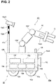
- FIG. 2 shows the configuration of a MoMa 10.
- This MoMa 10 includes the robot arm 10r as a manipulator, the moving apparatus 10a to which this robot arm 10r is attached, and various environment acquisition sensors 10s (examples of the "environment acquisition sensor") for acquiring environmental data E at the movement destination.
- the moving apparatus 10a includes a vehicle body 10b, wheels 10c for moving, and servo motors 10d for driving the wheels 10c.
- the inner portion of the vehicle body 10b includes a plurality of servo drivers 10e configured to respectively supply electric current for control to the servo motors 10d and servo motors 10d' for driving the robot arm 10r. Also, a battery 10f serving as a power source for constituting elements of the MoMa 10 and a controller 10g for individually controlling the robot arm 10r and the moving apparatus 10a are installed in the inner portion of the vehicle body 10b.
- the robot arm 10r is a multi-articulated robot constituted by a plurality of links L and the plurality of servo motors 10d' for driving these links L. Because the gripper G serving as an end effector is connected to the link L at the leading end, an object can be held at the movement destination. Also, an acceleration sensor 10s1 (an example of an "environment acquisition sensor") is installed inside the link L at its leading end. This robot arm 10r may also be provided with an image sensor (not shown) that is configured to recognize and hold an object.
- a support column 10h for mounting various environment acquisition sensors 10s are installed in the vehicle body 10b.
- This support column 10h is fixed substantially perpendicularly to an upper surface of the vehicle body 10b.
- An image sensor 10s2 (an example of the "environment acquisition sensor"), an illuminance sensor 10s3 (another example of the “environment acquisition sensor”), and a temperature sensor 10s4 (another example of the "environment acquisition sensor”) are mounted inside the upper portion of the support column 10h.
- a front surface of the vehicle body 10b is provided with a sound collecting microphone 10s5 (an example of the "environment acquisition sensor") for acquiring information on sound at the movement destination to which the MoMa 10 moves.
- the front surface of the vehicle body 10b is provided with a wireless antenna 10i for transmitting and receiving information such as the environmental data E to/from the outside, and a LRF (Laser Range Finder) 10j for measuring the distance to nearby objects.
- the LRF 10j is capable of measuring the distance to nearby objects by scanning a laser beam to its front and detecting the reflected beam.
- the MoMa 10 is capable of moving on the floor F without colliding with nearby objects, using the distance information received from the LRF 10j.
- FIG. 3 shows a diagram of the configuration of the controller 10g.
- the controller 10g includes a CPU 10k provided with a processor for arithmetic processing, such as a CPU (Central Processing Unit), a RAM 101 that is a volatile temporal storage device such as an SRAM (Random Access Memory), a ROM 10m that is a non-volatile semiconductor storage device (e.g., a NOR flash memory), and an HDD 10n (e.g., hard disk drive) that is an external storage device, and a communication interface 10p.
- a processor for arithmetic processing such as a CPU (Central Processing Unit)
- a RAM 101 that is a volatile temporal storage device such as an SRAM (Random Access Memory)
- ROM 10m that is a non-volatile semiconductor storage device (e.g., a NOR flash memory)
- HDD 10n e.g., hard disk drive
- the CPU 10k reads out a program stored in the ROM 101, or acquires a program from the outside using a wireless or wired communication interface 10p and executes the program.
- the RAM 101 is capable of using part of a program or calculation data for temporal storage.
- the ROM 10m is a storage medium for storing a program executed by the CPU 10k.
- the HDD 10n is a medium for storing information electrically, magnetically, optically, mechanically, chemically, or by their combination, such that the information can be read using an external device such as a computer, and the HDD 10n may be constituted by a CD, a DVD, a magnetic disk, an MO, a semiconductor flash memory such as a USB memory, or an HDD, for example.
- the HDD 10n is capable of storing a program executed by the CPU 10k (a program for determining a moving velocity or a moving path of the moving apparatus 10a of the MoMa 10, controlling and driving the moving apparatus 10a, a program for controlling and driving the robot arm 10r, a position estimation program for estimating the current position of the MoMa 10, and an amplitude estimation program for estimating the amplitude at the position of the movement destination) and the environmental data E acquired by the environment acquisition sensors 10s1 to 10s5, for example.
- a program executed by the CPU 10k a program for determining a moving velocity or a moving path of the moving apparatus 10a of the MoMa 10, controlling and driving the moving apparatus 10a, a program for controlling and driving the robot arm 10r, a position estimation program for estimating the current position of the MoMa 10, and an amplitude estimation program for estimating the amplitude at the position of the movement destination
- the environmental data E acquired by the environment acquisition sensors 10s1 to 10s5, for example.
- the communication interface 10p includes a wireless LAN (Local Area Network) interface for giving and receiving information to/from the outside via a wireless antenna 10i. Furthermore, the communication interface 10p is constituted by various interfaces for receiving information from the environment acquisition sensors 10s1 to 10s5 and LRF 10j. The communication interface 10p also includes interfaces with the servo drivers 10e, and is capable of acquiring the information on rotation positions of the links L via the servo drivers 10e, and transmitting data for control to the servo drivers 10e based on the information on these rotation positions.
- a wireless LAN Local Area Network
- controller 10g may also be constituted integrally with the servo drivers 10e.
- the ROM 10m of the controller 10g holds a program for calculating an electric current to be supplied to the servo motors 10d', and the CPU 10k reads out and executes this program.
- FIG. 4 shows a flowchart of a method for controlling the MoMa 10 according to the present embodiment. This arithmetic processing is executed by the CPU 10k that has read out the program stored in the ROM 10m or the HDD 10n.
- the MoMa 10 starts moving toward any position on the floor F in a factory (step S41).
- the controller 10g acquires data measured by the acceleration sensor 10s1 mounted in the link L of the robot arm 10r via the communication interface 10p, and determines whether or not the acceleration of the MoMa 10 is at least a predetermined threshold (step S42).
- step S42 if the acceleration is less than the threshold, the flowchart ends and the processing returns to step S41 again.
- step S42 if the acceleration is at least a predetermined threshold, the controller 10g transmits a control signal for controlling the servo motors 10d of the wheels 10c to the servo drivers 10e such that the MoMa 10 decelerates (step S43).
- these steps S41 to S43 are executed during constant-velocity movement at a predetermined time in a repetitive manner.
- the acceleration sensor 10s1 mounted inside the link L at the leading end of the robot arm 10r can be used for the purpose of measuring the acceleration of the robot arm 10r with respect to the vehicle body 10b, and measuring vibrations of the robot arm 10r while the robot arm 10r operates such as holding an object.
- this acceleration sensor 10s1 can be used in order to acquire information on vibrations (environmental data) originating from the surrounding environment at the movement destination to which the MoMa 10 moves (including a path on the way).
- the present invention can be applied without greatly changing the hardware configuration of the existing manipulator.
- the MoMa 10 passes through the vicinity of the apparatus M or M' that is a vibration source, the output value of data measured by the acceleration sensor 10s1 increases, and thus reducing the moving velocity of the MoMa 10 at this time makes it possible to avoid a situation in which the MoMa 10 resonates with vibrations of the apparatus M or M' and falls over.
- the MoMa in which a manipulator is installed in an upper portion of the vehicle body for example, has a high center of gravity and thus has a risk of falling over
- use of the MoMa 10 according to the present embodiment makes it possible to prevent the MoMa from falling over caused by an external vibration source.
- the threshold in step S42 may also dynamically change. Control may also be performed using the reciprocal of the value measured by the acceleration sensor S1 such that the MoMa 10 decelerates if the acceleration is not more than a predetermined threshold. In addition, the threshold or its range can be changed as appropriate.
- the MoMa 10 may also be configured to move along a predetermined moving path.
- a MoMa that autonomously selects a path in a predetermined region may select a path whose external environment is not known, and thus acquisition of environmental data by applying the control method according to the present embodiment has a great effect.
- the robot arm 10r can be applied widely to not only a device for holding an object with the gripper G but also a manipulator or the like for performing a predetermined operation.
- FIG. 5(a) shows a graph for predicting the acceleration based on the past acceleration.
- the horizontal axis represents the time, and the vertical axis represents the magnitude of the acceleration.
- a value V1 of the acceleration at a future time t 1 can be predicted by approximating a value of the acceleration at the current time t 0 and the previous time using a linear line L1.
- the next control cycle or a predetermined number of seconds can be set as the future time t 1 .
- step S'42 a configuration may also be adopted in which the predicted value V1 of the acceleration is compared with the threshold in step S'42, instead of step S42.
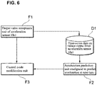
- FIG. 6 shows a diagram of functional blocks for executing a control method according to such a modification of the second embodiment. These functions can be realized by the controller 10g executing a program (an example of the "amplitude estimation program") that is stored in the ROM 10m or the HDD 10n.
- a program an example of the "amplitude estimation program”
- an output value acceptance unit F1 of the acceleration sensor 10s1 accepts information indicating the acceleration of the MoMa 10 that is output from the acceleration sensor 10s1.
- the accepted information indicating the acceleration is acquired in association with this time and the position of the MoMa at this time as time-series data D1.
- the data can be temporarily stored in the RAM 101, for example.
- An acceleration prediction unit F2 calculates a linear approximation line, and predicts the acceleration at the future time t 1 based on these pieces of time-series data.
- a control mode modification unit F3 switches to a control mode for operating at a low velocity.
- the output from the acceleration sensor 10s1 should gradually increase over time, and thus the value output from the acceleration sensor 10s1 at the future time can be predicted with high accuracy through linear approximation. Furthermore, it is possible to control the MoMa 10 so as to decelerate in advance, before the actual value of the acceleration sensor 10s1 is at least a predetermined value, and thus it is possible to prevent the MoMa 10 from falling over beforehand, for example. Note that approximation is not limited to linear approximation, and may also be nth order approximation (where n is an integer of at least 2).
- the object to be controlled is not limited to the moving velocity of the MoMa 10, and may also be the acceleration or a control gain of the MoMa 10, or a combination thereof.
- a configuration may also be adopted in which a normal control mode and a control mode for resonance suppression are stored in the ROM 10m in advance, and the control mode modification unit F3 switches the control mode in accordance with the output from the acceleration sensor 10s1.
- FIG. 5(b) is a graph showing a change in the moving velocity of the MoMa 10 when the acceleration and the velocity are controlled.
- the MoMa 10 when the MoMa 10 is originally controlled to accelerate at an acceleration of ⁇ 1 to a velocity v 1 , by controlling, in an environment with large vibrations, the MoMa 10 to accelerate at an acceleration of ⁇ 2 that is smaller than ⁇ 1 until reaching a velocity v 2 that is smaller than v 1 , the movement time required to move the same movement distance increases from t 2 to t 3 , but it is possible to reduce the inertial force applied to the robot arm 10r and make the MoMa 10 difficult to vibrate. Also, if the control gain is lowered, the property of tracking disturbance as vibrations is diminished, and thus resonance resulting from vibrations can be suppressed.
- the velocity may also be reduced by a predetermined amount that has been determined in advance, or may also be controlled using the value of the acceleration sensor 10s1 as a coefficient such that the larger the value of the acceleration sensor 10s1 is, the further the velocity decreases, for example.
- the MoMa 10 can be controlled by applying such a modification as described above such that resonance is suppressed before resonance starts, it is possible to effectively reduce a risk of falling over.
- a MoMa 10 according to the present embodiment is configured to control a moving apparatus 10a and a robot arm 10r utilizing a map that is created in association with positions in advance and that shows the amount of vibration.
- the map showing the amount of vibration here can be created by the MoMa 10 or another MoMa 10' moving all over the floor F.
- FIG. 7 shows a flowchart of a method for controlling the MoMa 10 according to the third embodiment.
- FIG. 8 shows a diagram of functional blocks for realizing such a control method. These functions can be realized by a CPU 10k of a controller 10g executing a program stored in a ROM 10M, for example.
- the MoMa 10 or another MoMa 10' moves all over the floor F.
- An output value acceptance unit F4 of an LRF acquires a value output from an LRF 10j while moving here.
- a generation unit F5 configured to generate a map showing a movable range (referred to as "mobility map” hereinafter) repeats a step of generating a map of its surroundings while estimating the position of the generation unit F5.
- Such a map can be generated using SLAM (Simultaneous Localization and Mapping).
- the generated mobility map is recorded in an HDD 10n as database D2, and is recorded in an external database via a wireless antenna 10i.
- An output value acceptance unit F7 of an acceleration sensor 10s1 of the MoMa 10 or the other MoMa 10' acquires environmental data E1 indicating the amount of vibration using the acceleration sensor 10s1 simultaneously.
- a generation unit F8 configured to generate a map showing vibration locations (referred to as "vibration map", hereinafter) generates a vibration map by associating the environmental data E1 with the position of the generation unit F8 that is estimated when the environmental data is acquired.
- the generated vibration map is recorded in an HDD 10n as database D3, and is recorded in an external database via a wireless antenna 10i (step S70). Generation of the vibration map is realized through the above-described steps (block B1).
- FIG. 9(a) shows a mobility map generated by the MoMa 10 moving on the floor F and an estimation position of the MoMa 10.
- a movable range P1 and an unmovable range P2 are shown.
- positions of apparatuses M and M' indicate the unmovable range P2.
- regions P and P' protruding from the floor surface of the floor F are recognized as the movable range P1.
- FIG. 9(b) shows the vibration map generated simultaneously with the mobility map generated by the MoMa moving on the floor F.
- the mobility map and the vibration map are not necessarily the same.
- environmental data E1 of the unmovable range P2 cannot be acquired, and thus there is no data about the unmovable range P2.
- the region P and a region P3 including its surrounding region and a region P' and a region P3' including its surrounding region are not the vibration sources, but they are insufficiently fixed to the floor surface, and thus are easily influenced by external vibrations.
- the regions P3 and P3' are movable regions, but large vibrations are observed and the MoMa easily falls over in these regions. Furthermore, these regions protrude from the floor surface, and thus the MoMa 10 more easily falls over in these regions.
- FIG. 10 is a perspective view of the vibration map in which the values of the acceleration sensor 10s1 are illustrated in a bar graph about a region P4 in FIG. 9(b) .
- the unit of the value of the acceleration sensor 10s1 is (m/s 2 ).
- FIG. 10 shows that as the distance to the apparatus M decreases, the larger the vibrations are. Note that the size of each region (an example of the "section") where the amount of vibration is acquired can be selected as appropriate. Also, with regard to a region where it is known that vibrations are small, the section may be set to be large, and with regard to a region with a high possibility of falling over, the section may be set to be small.
- Such a mobility map or a vibration map may also be generated using a plurality of MoMas 10 and 10', for example.
- the MoMa 10 acquires the mobility map and the vibration map through pre-processing (step S70) described above. If the MoMa 10 generates these maps, a map can be read out from the HDD 10n in which these maps are recorded. If another MoMa 10' generates a map, a map can be received from an external server through the wireless antenna 10i, for example.
- a position estimation unit F6 of the MoMa 10 estimates the position of the position estimation unit F6 by matching the output value obtained based on the LRF 10j and the mobility map.
- the mobility map is generated and the position of the estimation unit F6 is estimated as described above (block B1).
- a control mode modification unit F9 then acquires the amount of vibration at a position at which the MoMa 10 is present at the future time t1 (step S71).
- control mode modification unit F9 acquires the current estimation position of the MoMa 10. Also, because the moving path and the moving velocity of the MoMa 10 can be acquired, the position at the movement destination at the future time t1 can be calculated. The magnitude of a vibration at this position can be acquired with reference to the vibration map.
- step S72 it is determined whether or not the acquired magnitude of the vibration has at least a certain value (step S72), and if the magnitude of the vibration has a least the certain value, the control mode modification unit F9 changes the control mode to a low velocity mode, and reduces the velocity of the MoMa 10 by a certain amount (step S73).
- steps S72 and S73 are similar to steps S42 and S43 that were described above, and thus their description will be omitted.
- the environmental data E1 is acquired in association with the position at the movement destination in advance, and the moving velocity of the MoMa 10 is determined based on the acquired environmental data E1 using a method for controlling the MoMa 10 according to the present embodiment, it is possible to realize a control that is more adaptive to the environment and to suppress the risk of falling over or the like beforehand.
- vibrations that can cause falling over may be sometimes generated in a region far from the vibration source, and thus adopting the MoMa 10 and a control method therefor according to the present embodiment makes is possible to provide a MoMa that is more adaptive to the environment and a control method therefore.
- values of a plurality of the acceleration sensors regarding the same point may also be acquired by making MoMa repeatedly pass through the same point, and the environment map may also be generated using an average value, a median, or the maximum value of these values.
- the set of values of the acceleration sensors may also be smoothened using a method such as moving average. Smoothing in this manner makes it possible to estimate values of the acceleration sensor between moving points with high accuracy and to control the MoMa 10 based on the estimated values of the acceleration sensors with high accuracy.
- the value of the acceleration sensor is not more than a predetermined value and can be regarded as not influencing falling over, this value may also be regarded as zero or ignored.
- the vibration map may also be generated for types of MoMas to be moved, or types of workpieces or objects conveyed by a MoMa.
- Different MoMas have different masses, rigidities, and outer shapes, and thus have different amounts of vibrations.
- the weight and shape of a workpiece to be conveyed may influence vibrations.
- a threshold for changing a control may also be changed in accordance with types of MoMa and the operation content.
- Generation of the vibration map or the mobility map may also be realized using a plurality of MoMas through a communication network.
- a configuration may also be adopted in which these maps are stored in an external server and acquired at predetermined timing (for example, while a MoMa is charged) through the communication network.
- a method for controlling a MoMa 10 frequency analysis is performed on sections obtained by partitioning a floor F based on the above-described vibration map, and damping filters (an example of "environmental data") for suppressing vibrations in the sections are generated as environmental data E2 in association with the sections in advance.
- damping filters an example of "environmental data”
- environmental data E2 environmental data
- FIG. 11 is a flowchart showing such a control method.
- FIG. 12 is a diagram of functional blocks for realizing such a control method. However, blocks B1 and B2 in FIG. 12 are similar to those in FIG. 8 , and thus their description will be omitted.
- pre-processing (step S110) will be described below.
- the vibration map is divided into a plurality of sections (examples of "a plurality of points"). Automatic clustering may also be performed based on the vibration map or the vibration map may also be manually divided as a sectioning method.
- a damping filter is then generated for each section.
- a frequency analysis unit F10 analyzes frequencies of the sections based on information indicating the amount of vibration that is obtained from the vibration map and is obtained by the acceleration sensors 10s1 that are located inside or outside the sections.
- FIG. 13(a) shows the result of frequency analysis in a given section.
- the horizontal axis represents the frequency (Hz), and the vertical axis represents values (dB) indicating the magnitude of a vibration obtained by subjecting the amount of vibration (m/s 2 ) obtained by the acceleration sensor 10s1 to frequency analysis.
- vibrations appear which have a resonance frequency fv (Hz) as the resonance frequency of a peak, a width of fw (Hz), and a depth of d (dB).
- FIG. 13(b) shows a damping filter generated by the damping filter generation unit F11 based on the resonance frequency fv (Hz) of this vibration, its width, and its depth.
- the horizontal axis represents the frequency (Hz), and similarly to FIG. 13(a) , the vertical axis represents a value (dB) indicating the magnitude of the vibration.
- a damping filter (in FIG. 13(b) , a damping filter in which a frequency region with -3dB with respect to the reference is regarded as fw, and its depth is regarded as d (dB)) for suppressing vibrations with a desired frequency) is generated for each section in advance.
- FIG. 13(c) is a graph showing the frequency (horizontal axis) and the magnitude of the vibration (vertical axis) when a control to which a damping filter is applied is performed. As shown in this diagram, resonance can be effectively suppressed by applying such a damping filter that suppresses the acquired resonance frequency and performing the control.
- damping filters associated with the sections are recorded in the HDD 10n as database D4, and pre-processing ends (step S110).
- step S111 onward steps of applying an optimal damping filter while the MoMa 10 moves
- control mode modification unit F12 acquires a damping filter in a section to which the MoMa 10 moves next, from the database D4 based on the position that is estimated by the position estimation unit F6 (step S111).
- the acquired damping filter is then applied when the MoMa 10 actually enters this section. Specifically, when acquiring the amount of vibration at the position estimated by the position estimation unit F6 from the vibration map D3, and generating control data for controlling the moving apparatus 10a or the robot arm 10r of the MoMa 10, the control mode modification unit F12 applies the damping filter, generates control data, and controls the moving apparatus 10a or the robot arm 10r (step S112).
- step S113 when the MoMa 10 leaves this section, the damping filter is released (step S113). If there is a damping filter that is to be applied to a new section, the control mode modification unit F12 applies this damping filter, and similarly, generates control data for controlling the moving apparatus 10a or the robot arm 10r of the MoMa 10, and controls the moving apparatus 10a or the robot arm 10r.
- the MoMa 10 As described above, the MoMa 10 according to the present embodiment generates, as environmental data, a damping filter corresponding to the frequency of the vibration at each position (section) on the floor F in advance, and while the MoMa 10 is entering this section, this damping filter is applied and the MoMa 10 is controlled, and thus it is possible to realize a control according to an environment at the movement destination.
- the MoMa 10 is configured such that different damping filters are applied to the plurality of sections by providing each of the sections with a damping filter, and thus it is possible to control the MoMa 10 in a manner adaptive to each section.
- a configuration may also be adopted in which a damping filter adaptive to only some of the sections (sections where the MoMa 10 remains stationary and operates using a manipulator such as the robot arm 10r, for example) is applied to these sections.
- the servo motors 10d' of the robot arm 10r are each provided with a specific control signal, and frequency characteristics are acquired based on their feedback values.
- the servo motors 10d' are each provided with a swept sin signal at a point with a possibility of a large amount of vibration, and a feedback value of the servo motor 10d' that is closest to the gripper G whose frequency characteristics are easily obtained can be acquired as the frequency characteristics (information as in FIG. 13(a) ) at this position.
- Environmental data stored in association with the positions of the vibration map may also be created for each time period. For example, if the operating status of the factory changes in accordance with a time period, creating a vibration map for each time period makes it possible to perform a control that is more adaptive to the environment in this time period. That is, if there are a time period (e.g., from 8:00 a.m. to 9:00 a.m.) during which apparatuses are not operating in the factory, a time period (e.g., from 9:00 a.m.
- a configuration may also be adopted in which operating statuses of apparatuses that serve as vibration generation sources are acquired though a communication network and the vibration map (or environmental data associated with other position information) is updated in accordance with their operating statuses. For example, a vibration map when all of the apparatuses are operating is created in advance. The operating status of each apparatus (a state in which the power source of each apparatus is on or off) is acquired through the communication network, and the vibration map can be updated.
- a configuration may also be adopted in which, if information that the apparatus M is not operating is acquired, for example, the vibration map is updated where the amount of vibration around the apparatus M is regarded as zero, and the MoMa is controlled based on the updated vibration map.
- the sound collecting microphone 10s5 can be used instead of the acceleration sensor 10s1 for acquiring vibration information, or can be used in combination with the acceleration sensor 10s1.
- a moving path is then selected such that a path that is close to a direction in which the MoMa 10 moves and has a small specific frequency component is selected.
- Such a configuration makes it possible to realize a control according to an environment using a simple sound collecting microphone 10s5.
- a MoMa 10 according to this embodiment is configured to acquire temperature information in association with positions, as environmental data E3.
- Such a configuration makes it possible to suppress malfunctions of a manipulator such as a robot arm 10r resulting from tasks with high load under a high-temperature environment and to extend the lifetime of the manipulator.
- a manipulator such as a robot arm 10r
- the MoMa 10 instead of a human operator.
- tasks with high load are executed by the MoMa 10 at high temperature, abnormality and malfunctions of the MoMa easily occur.
- the MoMa 10 when the same MoMa 10 moves or operates under a room-temperature environment, the MoMa 10 needs to efficiently move or operate based on normal standards.
- the MoMa 10 acquires, using a temperature sensor 10s4, information on the temperatures of a plurality of positions in association with the positions.
- the MoMa 10 measures load factors of the servo motors 10d and 10d' using the servo drivers 10e.
- a controller 10g changes a command value for controlling the servo motors 10d or 10d'. For example, the controller 10g controls the servo motors 10d or 10d' such that the torque or electric current of the servo motors 10d or 10d' is reduced by a certain amount.
- load factors of the servo motors 10d or 10d' are measured using the servo drivers 10e, and if the load factor is below a predetermined value as a result of the control above, the controller 10g controls the servo motors 10d or 10d' such that their torque or electric current return to the original value.
- Such control makes it possible to execute tasks using a manipulator typified by the robot arm 10r while keeping the load factors of all of the servo motors 10d and 10d' at not more than predetermined values under a high-temperature environment.
- the MoMa 10 may also measure the load factors of the servo drivers 10e that supply electric current to the servo motors 10d and 10d', instead of measuring the load factors of the servo motors 10d and 10d', or in combination of measuring the load factors of the servo motors 10d and 10d'.
- the load factor of the servo driver 10e includes load applied to an element for generating electric current to be supplied to the servo motor 10d or 10d' having at least a predetermined value.
- the controller 10g reduces a target value to be transmitted to the servo driver 10e by a certain amount. Because the servo driver 10e reduces the electric current to be supplied to the servo motor 10d or 10d' based on the target value that was reduced by a certain amount, the load factor of the servo driver 10e decreases.
- configurations according to the present embodiment can be combined with configurations according to the other embodiments within the scope of ordinary creation by those skilled in the art.
- a configuration may also be adopted in which information on a map storing information on temperatures that were acquired by the MoMa or the other MoMa in advance in association with positions is generated, and a control is performed in accordance with the generated map information.
- a MoMa 10 according to the present embodiment is characterized by changing the control content in accordance with illuminance (an example of "environmental data") of lighting at the movement destination.
- the MoMa 10 has a configuration in which an image sensor (not shown) such as a CMOS image sensor is attached to a link at the leading end of the robot arm 10r, and the robot arm 10r is controlled using data on objects captured by this image sensor.
- an image sensor such as a CMOS image sensor
- this MoMa 10 includes an illuminance sensor 10s3, and thus is capable of acquiring information on the illuminance of a work environment.
- the MoMa 10 is configured to change the mode for controlling the image sensor in accordance with the acquired illuminance.
- a control is performed to lower its shutter speed below its standard, increase the gain of the image sensor, and open the diaphragm of its lens.
- information on the illuminance is stored in association with positions, and the MoMa 10 is controlled such that when the moving path is selected using a mobility map, a path with low illuminance is avoided and a path with high illuminance is selected as the moving path.
- the MoMa 10 is configured to be controlled in accordance with the illuminance at the movement destination, the MoMa 10 is capable of accurately recognizing an object, and thus it is possible to perform a control that is more adaptive to the environment.
- a modification of the MoMa 10 according to the above-described embodiment has a configuration in which the frequency of noise originating from lighting at the movement destination is acquired, a filter according to this frequency is applied to data obtained by an image sensor capturing an image, and image processing is performed.
- the lighting is a fluorescent lamp or an LED
- flickers occur at a predetermined frequency in some cases.
- a problem may arise under such an environment, such as a decrease in the image recognition capability of the image sensor.
- the MoMa 10 acquires and stores a reference image in advance under an ideal environment where causes of noise, such as flickers, are reduced.
- the MoMa 10 then captures an image of its surroundings at the movement destination using the image sensor, obtains a difference between the reference image and the captured image, and thereby calculates a frequency component of the lighting.
- the MoMa 10 then applies filtering to the image sensor, taking the calculated frequency component into consideration.
- Such a MoMa 10 is capable of dynamically eliminating noise depending on the lighting, it is possible to improve the image recognition capability of the MoMa 10.
- unit do not simply mean physical configurations but also include the case where processing executed by the "unit” and the like is realized by software. Processing performed by one "unit” and the like, or one apparatus may also be executed by two or more physical configurations or apparatuses, or processing performed by two or more "units” and the like, or two or more apparatuses may also be executed by one physical means or apparatus. Also, the following embodiments are merely examples for illustrating the present invention, and it is not intended to limit the invention to only these embodiments.
- a mobile manipulator (10) including:
Landscapes
- Engineering & Computer Science (AREA)
- Robotics (AREA)
- Mechanical Engineering (AREA)
- Physics & Mathematics (AREA)
- Radar, Positioning & Navigation (AREA)
- Automation & Control Theory (AREA)
- Remote Sensing (AREA)
- General Physics & Mathematics (AREA)
- Aviation & Aerospace Engineering (AREA)
- Human Computer Interaction (AREA)
- Health & Medical Sciences (AREA)
- General Health & Medical Sciences (AREA)
- Orthopedic Medicine & Surgery (AREA)
- Multimedia (AREA)
- Electromagnetism (AREA)
- Manipulator (AREA)
- Control Of Position, Course, Altitude, Or Attitude Of Moving Bodies (AREA)
Applications Claiming Priority (1)
| Application Number | Priority Date | Filing Date | Title |
|---|---|---|---|
| JP2017215398A JP7051045B2 (ja) | 2017-11-08 | 2017-11-08 | 移動式マニピュレータ、移動式マニピュレータの制御方法及びプログラム |
Publications (2)
| Publication Number | Publication Date |
|---|---|
| EP3482884A1 true EP3482884A1 (de) | 2019-05-15 |
| EP3482884B1 EP3482884B1 (de) | 2022-06-08 |
Family
ID=63798744
Family Applications (1)
| Application Number | Title | Priority Date | Filing Date |
|---|---|---|---|
| EP18194567.6A Active EP3482884B1 (de) | 2017-11-08 | 2018-09-14 | Mobiler manipulator, verfahren zur steuerung eines mobilen manipulators und programm dafür |
Country Status (4)
| Country | Link |
|---|---|
| US (1) | US10948917B2 (de) |
| EP (1) | EP3482884B1 (de) |
| JP (1) | JP7051045B2 (de) |
| CN (1) | CN109746910B (de) |
Cited By (3)
| Publication number | Priority date | Publication date | Assignee | Title |
|---|---|---|---|---|
| EP3796115A1 (de) * | 2019-09-19 | 2021-03-24 | Hitachi, Ltd. | Anomaliedetektion für roboterarme unter verwendung von vibrationsdaten |
| WO2022132789A1 (en) * | 2020-12-15 | 2022-06-23 | Milwaukee Electric Tool Corporation | Battery pack powered robotic devices |
| WO2022203980A1 (en) * | 2021-03-26 | 2022-09-29 | Boston Dynamics, Inc. | Dynamic mass estimation methods for an integrated mobile manipulator robot |
Families Citing this family (31)
| Publication number | Priority date | Publication date | Assignee | Title |
|---|---|---|---|---|
| JP6621059B2 (ja) * | 2017-11-28 | 2019-12-18 | 株式会社安川電機 | 機械設備制御システム、機械設備制御装置、及び機械設備制御方法 |
| WO2019167207A1 (ja) | 2018-02-28 | 2019-09-06 | 本田技研工業株式会社 | 制御装置、作業機及びプログラム |
| US10751888B2 (en) * | 2018-10-04 | 2020-08-25 | Advanced Intelligent Systems Inc. | Manipulator apparatus for operating on articles |
| US11559897B2 (en) * | 2018-10-26 | 2023-01-24 | George K. Ghanem | Reconfigurable, fixtureless manufacturing system and method assisted by learning software |
| US12106188B2 (en) | 2018-10-26 | 2024-10-01 | George K. Ghanem | Learning software assisted fixtureless object pickup and placement system and method |
| US12134193B2 (en) | 2018-10-26 | 2024-11-05 | George K. Ghanem | Learning software assisted object joining |
| US12214496B2 (en) | 2018-10-26 | 2025-02-04 | George K. Ghanem | Learning software assisted automated manufacture |
| US11597083B2 (en) * | 2018-12-17 | 2023-03-07 | Canon Kabushiki Kaisha | Robot apparatus, robot system, control method of robot apparatus, product manufacturing method using robot apparatus, and storage medium |
| US11623339B1 (en) * | 2019-05-16 | 2023-04-11 | Amazon Technologies, Inc. | Portable robotic manipulation systems |
| CN110370293B (zh) * | 2019-06-13 | 2021-03-23 | 苏州吉成智能科技有限公司 | 双机械手药房控制系统用的药品发放方法以及装置 |
| CN110238812A (zh) * | 2019-06-17 | 2019-09-17 | 东北大学 | 一种快递分拣机器人 |
| CN110815212A (zh) * | 2019-10-09 | 2020-02-21 | 上海晟申重机装备有限公司 | 一种焦炉装煤口的智能石墨清扫装置 |
| US11224972B2 (en) | 2019-11-22 | 2022-01-18 | Fanuc Corporation | State machine for dynamic path planning |
| JP7188363B2 (ja) * | 2019-11-25 | 2022-12-13 | トヨタ自動車株式会社 | 搬送システム、搬送方法およびプログラム |
| EP3825553B1 (de) * | 2019-11-25 | 2024-01-10 | Grundfos Holding A/S | Verfahren zur steuerung einer wassernutzanlage mittels einer geräuschwahrnehmung durch einen benutzer |
| JP7192748B2 (ja) | 2019-11-25 | 2022-12-20 | トヨタ自動車株式会社 | 搬送システム、学習済みモデル生成方法、学習済みモデル、制御方法およびプログラム |
| CN113031530B (zh) * | 2019-12-09 | 2022-06-10 | 合肥欣奕华智能机器股份有限公司 | 一种机器人的控制方法、其控制装置及机器人 |
| JP7500191B2 (ja) * | 2019-12-20 | 2024-06-17 | キヤノン株式会社 | ロボットシステム、搬送車、ロボットシステムの制御方法、物品の製造方法、制御プログラム及び記録媒体 |
| JP7415576B2 (ja) | 2020-01-15 | 2024-01-17 | セイコーエプソン株式会社 | ロボットの制御方法、及び、ロボットシステム |
| JP7487479B2 (ja) * | 2020-01-23 | 2024-05-21 | セイコーエプソン株式会社 | 移動ロボットの制御方法 |
| US12403585B2 (en) * | 2020-05-22 | 2025-09-02 | Fanuc Corporation | Robot system |
| CN112013835B (zh) * | 2020-09-21 | 2022-08-26 | 珠海格力智能装备有限公司 | 地图装置、导航车、服务器、存储介质、导航系统及方法 |
| TWI899391B (zh) * | 2020-12-21 | 2025-10-01 | 日商發那科股份有限公司 | 機器人控制裝置及機器人系統 |
| JP6957781B1 (ja) * | 2021-06-14 | 2021-11-02 | Dmg森精機株式会社 | 自走装置 |
| US12511778B2 (en) | 2021-07-30 | 2025-12-30 | Canon Kabushiki Kaisha | Information processing apparatus, information processing method, and storage medium |
| JP7746061B2 (ja) * | 2021-07-30 | 2025-09-30 | キヤノン株式会社 | 情報処理装置、情報処理方法、及びプログラム |
| CN113799105B (zh) * | 2021-11-17 | 2022-02-08 | 季华实验室 | 一种复合机器人的防倾覆系统 |
| US12496724B1 (en) | 2022-05-03 | 2025-12-16 | Processchamp, Llc | Systems and methods for mounting wheels to partially assembled vehicles in motion |
| US12496668B1 (en) | 2022-05-03 | 2025-12-16 | Processchamp, Llc | Systems and methods for installing a first component to a second component in motion |
| WO2024044975A1 (zh) * | 2022-08-30 | 2024-03-07 | 西门子股份公司 | 移动机械臂的控制方法及装置 |
| CN119260721B (zh) * | 2024-10-29 | 2025-06-24 | 北京和崎精密科技有限公司 | 一种基于震动感知器的机械手误撞击控制方法及系统 |
Citations (4)
| Publication number | Priority date | Publication date | Assignee | Title |
|---|---|---|---|---|
| US8452449B2 (en) * | 2009-07-06 | 2013-05-28 | Seiko Epson Corporation | Position control method and robot |
| JP2014030857A (ja) | 2012-08-01 | 2014-02-20 | Seiko Epson Corp | ロボット及び搬送装置 |
| JP2014119903A (ja) | 2012-12-14 | 2014-06-30 | Omron Corp | 制御装置、制御プログラムおよび制御方法 |
| US20150306767A1 (en) * | 2014-04-24 | 2015-10-29 | Toyota Jidosha Kabushiki Kaisha | Motion limiting device and motion limiting method |
Family Cites Families (47)
| Publication number | Priority date | Publication date | Assignee | Title |
|---|---|---|---|---|
| US293163A (en) * | 1884-02-05 | Band sawing machine | ||
| DD239163A1 (de) * | 1985-07-04 | 1986-09-17 | Wtz Arbeitsschutz | Einrichtung zur schwingungsminderung von kraftfahrzeugen, insbesondere baumaschinen |
| JPH06114762A (ja) * | 1992-10-02 | 1994-04-26 | Toyota Motor Corp | 制振制御方法 |
| JPH0958998A (ja) * | 1995-08-24 | 1997-03-04 | Tamagawa Seiki Co Ltd | 搬送車の振れ防止方法 |
| US7031802B2 (en) * | 2003-08-13 | 2006-04-18 | Hewlett-Packard Development Company, L.P. | Semi-autonomous operation of a robotic device |
| JP2005092297A (ja) * | 2003-09-12 | 2005-04-07 | Yaskawa Electric Corp | 振動抑制フィルタの自動設定方法 |
| KR100652587B1 (ko) * | 2004-09-23 | 2006-12-06 | 엘지전자 주식회사 | 로봇청소기를 이용한 화재 경보 알림 시스템 및 방법 |
| US7650013B2 (en) * | 2004-11-15 | 2010-01-19 | Mobilerobots Inc. | System and method for map and position-determination enhancement |
| US7112939B2 (en) * | 2004-12-07 | 2006-09-26 | Electronics And Telecommunications Research Institute | Mobile system and driving method thereof |
| GB0609318D0 (en) * | 2006-05-11 | 2006-06-21 | Autokontrol Ltd | Speed limiter system |
| JP4608472B2 (ja) * | 2006-10-02 | 2011-01-12 | 本田技研工業株式会社 | 移動ロボット及び移動ロボットの制御装置 |
| JP2008225837A (ja) * | 2007-03-13 | 2008-09-25 | Toyota Motor Corp | 移動体位置検出システム及び移動体位置検出方法 |
| WO2009037715A1 (en) * | 2007-09-21 | 2009-03-26 | Pricol Limited | A dual speed electronic speed governor system and method thereof |
| US9757069B2 (en) * | 2008-01-11 | 2017-09-12 | Staton Techiya, Llc | SPL dose data logger system |
| JP5188316B2 (ja) * | 2008-08-06 | 2013-04-24 | 株式会社Ihi | 移動ロボット及び移動ロボットの走行速度制御方法 |
| JP5024896B2 (ja) * | 2008-09-12 | 2012-09-12 | トヨタ自動車株式会社 | 移動ロボットの操縦システム |
| JP5110405B2 (ja) * | 2010-04-07 | 2012-12-26 | 村田機械株式会社 | 走行台車システム |
| JP5499865B2 (ja) * | 2010-04-19 | 2014-05-21 | パナソニック株式会社 | 多関節型ロボットの速度指令プロファイルの生成方法 |
| JP5645564B2 (ja) * | 2010-09-14 | 2014-12-24 | キヤノン株式会社 | センサ装置及びロボット装置 |
| EP2702577B1 (de) * | 2011-04-27 | 2019-06-12 | Telecom Italia S.p.A. | System und verfahren zur überwachung eines gebietes |
| JP2012232370A (ja) * | 2011-04-28 | 2012-11-29 | Seiko Epson Corp | ロボットコントローラー、簡易設置型ロボット、及び簡易設置型ロボットの制御方法 |
| HUP1200197A2 (hu) * | 2012-04-03 | 2013-10-28 | Budapesti Mueszaki Es Gazdasagtudomanyi Egyetem | Eljárás és elrendezés környezeti zaj valós idejû, forrásszelektív monitorozására és térképezésére |
| US9031779B2 (en) * | 2012-05-30 | 2015-05-12 | Toyota Motor Engineering & Manufacturing North America, Inc. | System and method for hazard detection and sharing |
| JP2014048193A (ja) * | 2012-08-31 | 2014-03-17 | Hitachi-Ge Nuclear Energy Ltd | 原子炉内作業装置およびその装置を使用した作業方法 |
| KR20150091346A (ko) * | 2012-11-30 | 2015-08-10 | 어플라이드 머티어리얼스, 인코포레이티드 | 진동-제어되는 기판 핸들링 로봇, 시스템들, 및 방법들 |
| US20140192990A1 (en) * | 2013-01-10 | 2014-07-10 | Wilson Cheng | Virtual Audio Map |
| WO2014155559A1 (ja) * | 2013-03-27 | 2014-10-02 | 株式会社安川電機 | ノッチフィルタ、外力推定器、モータ制御装置およびロボットシステム |
| CN105122800A (zh) * | 2013-04-17 | 2015-12-02 | 韦勒斯标准与技术协会公司 | 视频信号处理方法及装置 |
| DE102013207899A1 (de) * | 2013-04-30 | 2014-10-30 | Kuka Laboratories Gmbh | Fahrerloses Transportfahrzeug, System mit einem Rechner und einem fahrerlosen Transportfahrzeug, Verfahren zum Planen einer virtuellen Spur und Verfahren zum Betreiben eines fahrerlosen Transportfahrzeugs |
| CN103472823B (zh) * | 2013-08-20 | 2015-11-18 | 苏州两江科技有限公司 | 一种智能机器人用的栅格地图创建方法 |
| US9248837B2 (en) * | 2014-03-11 | 2016-02-02 | Tata Consultancy Services Limited | Method and system for controlling a speed of a vehicle |
| JP2016115218A (ja) * | 2014-12-16 | 2016-06-23 | 多摩川精機株式会社 | 振動抑制システム、振動抑制指令装置、制振仕様装置およびロボット |
| AU2016230236B2 (en) * | 2015-03-10 | 2019-07-25 | Komatsu Ltd. | Control system for work vehicle, control method, and work vehicle |
| JP6428453B2 (ja) * | 2015-04-06 | 2018-11-28 | トヨタ自動車株式会社 | ロボット制御方法及びロボット制御装置 |
| US9358975B1 (en) * | 2015-04-10 | 2016-06-07 | Google Inc. | Virtual moving safety limits for vehicles transporting objects |
| BR102016008666B1 (pt) * | 2015-05-12 | 2022-10-11 | Autonomous Solutions, Inc. | Sistema de controle para uma estação-base, método para controlar um veículo agrícola e sistema agrícola autônomo |
| JP6539125B2 (ja) * | 2015-06-22 | 2019-07-03 | 株式会社日立製作所 | 移動ロボットシステム及び移動ロボットの制御方法 |
| JP6762148B2 (ja) * | 2015-07-09 | 2020-09-30 | パナソニック インテレクチュアル プロパティ コーポレーション オブ アメリカPanasonic Intellectual Property Corporation of America | 地図生成方法、移動ロボット及び地図生成システム |
| US20170103420A1 (en) * | 2015-10-12 | 2017-04-13 | ArcSecond, Inc. | Generating a Contextual-Based Sound Map |
| US9904283B2 (en) * | 2016-03-08 | 2018-02-27 | Fuji Xerox Co., Ltd. | Systems and methods employing coded light to dock aerial drones, self-driving cars and surface robots |
| JP2017196704A (ja) * | 2016-04-28 | 2017-11-02 | セイコーエプソン株式会社 | 可動部の振動測定方法、ロボットの振動測定方法および制御装置 |
| US20170372242A1 (en) * | 2016-06-27 | 2017-12-28 | Hartford Fire Insurance Company | System to monitor and process noise level exposure data |
| CN106313056B (zh) * | 2016-10-26 | 2019-04-30 | 重庆大学 | 扫雪机器人障碍物检测方法 |
| WO2018148356A1 (en) * | 2017-02-10 | 2018-08-16 | Honeywell International Inc. | Distributed network of communicatively coupled noise monitoring and mapping devices |
| US9892744B1 (en) * | 2017-02-13 | 2018-02-13 | International Business Machines Corporation | Acoustics based anomaly detection in machine rooms |
| JP6897376B2 (ja) * | 2017-07-11 | 2021-06-30 | トヨタ自動車株式会社 | 移動計画装置、移動ロボット、および移動計画プログラム |
| WO2019084686A1 (en) * | 2017-10-31 | 2019-05-09 | Clearpath Robotics Inc. | Systems and methods for operating robotic equipment in controlled zones |
-
2017
- 2017-11-08 JP JP2017215398A patent/JP7051045B2/ja active Active
-
2018
- 2018-09-11 CN CN201811060476.9A patent/CN109746910B/zh active Active
- 2018-09-14 EP EP18194567.6A patent/EP3482884B1/de active Active
- 2018-09-18 US US16/134,464 patent/US10948917B2/en active Active
Patent Citations (4)
| Publication number | Priority date | Publication date | Assignee | Title |
|---|---|---|---|---|
| US8452449B2 (en) * | 2009-07-06 | 2013-05-28 | Seiko Epson Corporation | Position control method and robot |
| JP2014030857A (ja) | 2012-08-01 | 2014-02-20 | Seiko Epson Corp | ロボット及び搬送装置 |
| JP2014119903A (ja) | 2012-12-14 | 2014-06-30 | Omron Corp | 制御装置、制御プログラムおよび制御方法 |
| US20150306767A1 (en) * | 2014-04-24 | 2015-10-29 | Toyota Jidosha Kabushiki Kaisha | Motion limiting device and motion limiting method |
Non-Patent Citations (1)
| Title |
|---|
| ABHIJEET RAVANKAR ET AL: "Symbiotic Navigation in Multi-Robot Systems with Remote Obstacle Knowledge Sharing", SENSORS, vol. 17, no. 7, 5 July 2017 (2017-07-05), pages 1581, XP055576802, DOI: 10.3390/s17071581 * |
Cited By (8)
| Publication number | Priority date | Publication date | Assignee | Title |
|---|---|---|---|---|
| EP3796115A1 (de) * | 2019-09-19 | 2021-03-24 | Hitachi, Ltd. | Anomaliedetektion für roboterarme unter verwendung von vibrationsdaten |
| WO2022132789A1 (en) * | 2020-12-15 | 2022-06-23 | Milwaukee Electric Tool Corporation | Battery pack powered robotic devices |
| EP4263142A4 (de) * | 2020-12-15 | 2024-10-30 | Milwaukee Electric Tool Corporation | Batteriesatzbetriebene robotervorrichtungen |
| US12440999B2 (en) | 2020-12-15 | 2025-10-14 | Milwaukee Electric Tool Corporation | Battery pack powered robotic devices |
| WO2022203980A1 (en) * | 2021-03-26 | 2022-09-29 | Boston Dynamics, Inc. | Dynamic mass estimation methods for an integrated mobile manipulator robot |
| CN117460601A (zh) * | 2021-03-26 | 2024-01-26 | 波士顿动力公司 | 集成移动机械手机器人的动态质量估计方法 |
| US12240105B2 (en) | 2021-03-26 | 2025-03-04 | Boston Dynamics, Inc. | Dynamic mass estimation methods for an integrated mobile manipulator robot |
| AU2022241986B2 (en) * | 2021-03-26 | 2026-03-12 | Boston Dynamics, Inc. | Dynamic mass estimation methods for an integrated mobile manipulator robot |
Also Published As
| Publication number | Publication date |
|---|---|
| US20190138009A1 (en) | 2019-05-09 |
| JP2019087073A (ja) | 2019-06-06 |
| JP7051045B2 (ja) | 2022-04-11 |
| EP3482884B1 (de) | 2022-06-08 |
| CN109746910B (zh) | 2022-04-12 |
| US10948917B2 (en) | 2021-03-16 |
| CN109746910A (zh) | 2019-05-14 |
Similar Documents
| Publication | Publication Date | Title |
|---|---|---|
| EP3482884B1 (de) | Mobiler manipulator, verfahren zur steuerung eines mobilen manipulators und programm dafür | |
| US11241796B2 (en) | Robot system and method for controlling robot system | |
| US11577399B2 (en) | Robot system, method for controlling robot, robot controller, and non-transitory computer-readable storage medium | |
| KR101971317B1 (ko) | 삼차원 물체 인식 장치, 삼차원 물체 인식 방법 및, 이동체 | |
| KR101475826B1 (ko) | 백스테핑 기법을 이용한 선도 추종자 대형제어 장치, 방법 및 이동로봇 | |
| US10377581B2 (en) | Article conveying device using at least one sensor | |
| JP7199003B2 (ja) | 搬送装置、受信機能付き搬送装置、搬送システム、上位システム、搬送装置の制御方法、及びプログラム | |
| JP2009545457A (ja) | 機械の衝突防止のためのカメラを利用した監視方法及び装置 | |
| KR20190088824A (ko) | 로봇 청소기 및 그 제어 방법 | |
| KR102701952B1 (ko) | 제어 방법, 제어 장치, 로봇 시스템, 프로그램 및 기록 매체 | |
| US20220333922A1 (en) | Deterioration determination apparatus, deterioration determination method, and computer-readable storage medium storing a control program | |
| US20190232491A1 (en) | Work robot system | |
| US11921515B1 (en) | System and method for confining robotic devices | |
| CN115605329B (zh) | 随动机器人 | |
| US20190196488A1 (en) | Standing Test Device for Mobile Robots | |
| JP7331446B2 (ja) | 制御装置、無人搬送車、無人搬送車の制御方法および制御プログラム | |
| JP2025096413A (ja) | 地図補正システム、及び地図補正プログラム | |
| WO2021246169A1 (ja) | 情報処理装置、情報処理システム、および方法、並びにプログラム | |
| CN114929436A (zh) | 用于控制机器人的系统和方法、电子设备和计算机可读介质 | |
| JP7272221B2 (ja) | 情報処理装置、ロボット、および情報処理システム | |
| JP2022516913A (ja) | エンドデバイス、エンドデバイスを制御するためのエッジサーバ、およびクラウドサーバを含む三者間通信システムとこの動作方法 | |
| US20250251735A1 (en) | System and method for confining robotic devices | |
| US20250065503A1 (en) | Collision prediction method, collision prediction device, and welding system | |
| JP2023132875A (ja) | 走行ロボットシステム | |
| JP2026068190A (ja) | 自律移動ロボット、自律移動ロボット制御方法、自律移動ロボット制御プログラムおよび記録媒体 |
Legal Events
| Date | Code | Title | Description |
|---|---|---|---|
| PUAI | Public reference made under article 153(3) epc to a published international application that has entered the european phase |
Free format text: ORIGINAL CODE: 0009012 |
|
| STAA | Information on the status of an ep patent application or granted ep patent |
Free format text: STATUS: REQUEST FOR EXAMINATION WAS MADE |
|
| 17P | Request for examination filed |
Effective date: 20180914 |
|
| AK | Designated contracting states |
Kind code of ref document: A1 Designated state(s): AL AT BE BG CH CY CZ DE DK EE ES FI FR GB GR HR HU IE IS IT LI LT LU LV MC MK MT NL NO PL PT RO RS SE SI SK SM TR |
|
| AX | Request for extension of the european patent |
Extension state: BA ME |
|
| STAA | Information on the status of an ep patent application or granted ep patent |
Free format text: STATUS: EXAMINATION IS IN PROGRESS |
|
| 17Q | First examination report despatched |
Effective date: 20210329 |
|
| GRAP | Despatch of communication of intention to grant a patent |
Free format text: ORIGINAL CODE: EPIDOSNIGR1 |
|
| STAA | Information on the status of an ep patent application or granted ep patent |
Free format text: STATUS: GRANT OF PATENT IS INTENDED |
|
| INTG | Intention to grant announced |
Effective date: 20220315 |
|
| GRAS | Grant fee paid |
Free format text: ORIGINAL CODE: EPIDOSNIGR3 |
|
| GRAA | (expected) grant |
Free format text: ORIGINAL CODE: 0009210 |
|
| STAA | Information on the status of an ep patent application or granted ep patent |
Free format text: STATUS: THE PATENT HAS BEEN GRANTED |
|
| AK | Designated contracting states |
Kind code of ref document: B1 Designated state(s): AL AT BE BG CH CY CZ DE DK EE ES FI FR GB GR HR HU IE IS IT LI LT LU LV MC MK MT NL NO PL PT RO RS SE SI SK SM TR |
|
| REG | Reference to a national code |
Ref country code: AT Ref legal event code: REF Ref document number: 1496600 Country of ref document: AT Kind code of ref document: T Effective date: 20220615 Ref country code: CH Ref legal event code: EP |
|
| REG | Reference to a national code |
Ref country code: DE Ref legal event code: R096 Ref document number: 602018036428 Country of ref document: DE |
|
| REG | Reference to a national code |
Ref country code: IE Ref legal event code: FG4D |
|
| REG | Reference to a national code |
Ref country code: LT Ref legal event code: MG9D |
|
| REG | Reference to a national code |
Ref country code: NL Ref legal event code: MP Effective date: 20220608 |
|
| PG25 | Lapsed in a contracting state [announced via postgrant information from national office to epo] |
Ref country code: SE Free format text: LAPSE BECAUSE OF FAILURE TO SUBMIT A TRANSLATION OF THE DESCRIPTION OR TO PAY THE FEE WITHIN THE PRESCRIBED TIME-LIMIT Effective date: 20220608 Ref country code: NO Free format text: LAPSE BECAUSE OF FAILURE TO SUBMIT A TRANSLATION OF THE DESCRIPTION OR TO PAY THE FEE WITHIN THE PRESCRIBED TIME-LIMIT Effective date: 20220908 Ref country code: LT Free format text: LAPSE BECAUSE OF FAILURE TO SUBMIT A TRANSLATION OF THE DESCRIPTION OR TO PAY THE FEE WITHIN THE PRESCRIBED TIME-LIMIT Effective date: 20220608 Ref country code: HR Free format text: LAPSE BECAUSE OF FAILURE TO SUBMIT A TRANSLATION OF THE DESCRIPTION OR TO PAY THE FEE WITHIN THE PRESCRIBED TIME-LIMIT Effective date: 20220608 Ref country code: GR Free format text: LAPSE BECAUSE OF FAILURE TO SUBMIT A TRANSLATION OF THE DESCRIPTION OR TO PAY THE FEE WITHIN THE PRESCRIBED TIME-LIMIT Effective date: 20220909 Ref country code: FI Free format text: LAPSE BECAUSE OF FAILURE TO SUBMIT A TRANSLATION OF THE DESCRIPTION OR TO PAY THE FEE WITHIN THE PRESCRIBED TIME-LIMIT Effective date: 20220608 Ref country code: ES Free format text: LAPSE BECAUSE OF FAILURE TO SUBMIT A TRANSLATION OF THE DESCRIPTION OR TO PAY THE FEE WITHIN THE PRESCRIBED TIME-LIMIT Effective date: 20220608 Ref country code: BG Free format text: LAPSE BECAUSE OF FAILURE TO SUBMIT A TRANSLATION OF THE DESCRIPTION OR TO PAY THE FEE WITHIN THE PRESCRIBED TIME-LIMIT Effective date: 20220908 |
|
| REG | Reference to a national code |
Ref country code: AT Ref legal event code: MK05 Ref document number: 1496600 Country of ref document: AT Kind code of ref document: T Effective date: 20220608 |
|
| PG25 | Lapsed in a contracting state [announced via postgrant information from national office to epo] |
Ref country code: RS Free format text: LAPSE BECAUSE OF FAILURE TO SUBMIT A TRANSLATION OF THE DESCRIPTION OR TO PAY THE FEE WITHIN THE PRESCRIBED TIME-LIMIT Effective date: 20220608 Ref country code: LV Free format text: LAPSE BECAUSE OF FAILURE TO SUBMIT A TRANSLATION OF THE DESCRIPTION OR TO PAY THE FEE WITHIN THE PRESCRIBED TIME-LIMIT Effective date: 20220608 |
|
| PG25 | Lapsed in a contracting state [announced via postgrant information from national office to epo] |
Ref country code: NL Free format text: LAPSE BECAUSE OF FAILURE TO SUBMIT A TRANSLATION OF THE DESCRIPTION OR TO PAY THE FEE WITHIN THE PRESCRIBED TIME-LIMIT Effective date: 20220608 |
|
| PG25 | Lapsed in a contracting state [announced via postgrant information from national office to epo] |
Ref country code: SM Free format text: LAPSE BECAUSE OF FAILURE TO SUBMIT A TRANSLATION OF THE DESCRIPTION OR TO PAY THE FEE WITHIN THE PRESCRIBED TIME-LIMIT Effective date: 20220608 Ref country code: SK Free format text: LAPSE BECAUSE OF FAILURE TO SUBMIT A TRANSLATION OF THE DESCRIPTION OR TO PAY THE FEE WITHIN THE PRESCRIBED TIME-LIMIT Effective date: 20220608 Ref country code: RO Free format text: LAPSE BECAUSE OF FAILURE TO SUBMIT A TRANSLATION OF THE DESCRIPTION OR TO PAY THE FEE WITHIN THE PRESCRIBED TIME-LIMIT Effective date: 20220608 Ref country code: PT Free format text: LAPSE BECAUSE OF FAILURE TO SUBMIT A TRANSLATION OF THE DESCRIPTION OR TO PAY THE FEE WITHIN THE PRESCRIBED TIME-LIMIT Effective date: 20221010 Ref country code: EE Free format text: LAPSE BECAUSE OF FAILURE TO SUBMIT A TRANSLATION OF THE DESCRIPTION OR TO PAY THE FEE WITHIN THE PRESCRIBED TIME-LIMIT Effective date: 20220608 Ref country code: CZ Free format text: LAPSE BECAUSE OF FAILURE TO SUBMIT A TRANSLATION OF THE DESCRIPTION OR TO PAY THE FEE WITHIN THE PRESCRIBED TIME-LIMIT Effective date: 20220608 Ref country code: AT Free format text: LAPSE BECAUSE OF FAILURE TO SUBMIT A TRANSLATION OF THE DESCRIPTION OR TO PAY THE FEE WITHIN THE PRESCRIBED TIME-LIMIT Effective date: 20220608 |
|
| PG25 | Lapsed in a contracting state [announced via postgrant information from national office to epo] |
Ref country code: PL Free format text: LAPSE BECAUSE OF FAILURE TO SUBMIT A TRANSLATION OF THE DESCRIPTION OR TO PAY THE FEE WITHIN THE PRESCRIBED TIME-LIMIT Effective date: 20220608 Ref country code: IS Free format text: LAPSE BECAUSE OF FAILURE TO SUBMIT A TRANSLATION OF THE DESCRIPTION OR TO PAY THE FEE WITHIN THE PRESCRIBED TIME-LIMIT Effective date: 20221008 |
|
| REG | Reference to a national code |
Ref country code: DE Ref legal event code: R097 Ref document number: 602018036428 Country of ref document: DE |
|
| PG25 | Lapsed in a contracting state [announced via postgrant information from national office to epo] |
Ref country code: AL Free format text: LAPSE BECAUSE OF FAILURE TO SUBMIT A TRANSLATION OF THE DESCRIPTION OR TO PAY THE FEE WITHIN THE PRESCRIBED TIME-LIMIT Effective date: 20220608 |
|
| PLBE | No opposition filed within time limit |
Free format text: ORIGINAL CODE: 0009261 |
|
| STAA | Information on the status of an ep patent application or granted ep patent |
Free format text: STATUS: NO OPPOSITION FILED WITHIN TIME LIMIT |
|
| PG25 | Lapsed in a contracting state [announced via postgrant information from national office to epo] |
Ref country code: MC Free format text: LAPSE BECAUSE OF FAILURE TO SUBMIT A TRANSLATION OF THE DESCRIPTION OR TO PAY THE FEE WITHIN THE PRESCRIBED TIME-LIMIT Effective date: 20220608 Ref country code: DK Free format text: LAPSE BECAUSE OF FAILURE TO SUBMIT A TRANSLATION OF THE DESCRIPTION OR TO PAY THE FEE WITHIN THE PRESCRIBED TIME-LIMIT Effective date: 20220608 |
|
| REG | Reference to a national code |
Ref country code: CH Ref legal event code: PL |
|
| 26N | No opposition filed |
Effective date: 20230310 |
|
| GBPC | Gb: european patent ceased through non-payment of renewal fee |
Effective date: 20220914 |
|
| REG | Reference to a national code |
Ref country code: BE Ref legal event code: MM Effective date: 20220930 |
|
| PG25 | Lapsed in a contracting state [announced via postgrant information from national office to epo] |
Ref country code: SI Free format text: LAPSE BECAUSE OF FAILURE TO SUBMIT A TRANSLATION OF THE DESCRIPTION OR TO PAY THE FEE WITHIN THE PRESCRIBED TIME-LIMIT Effective date: 20220608 |
|
| PG25 | Lapsed in a contracting state [announced via postgrant information from national office to epo] |
Ref country code: LU Free format text: LAPSE BECAUSE OF NON-PAYMENT OF DUE FEES Effective date: 20220914 |
|
| PG25 | Lapsed in a contracting state [announced via postgrant information from national office to epo] |
Ref country code: LI Free format text: LAPSE BECAUSE OF NON-PAYMENT OF DUE FEES Effective date: 20220930 Ref country code: IE Free format text: LAPSE BECAUSE OF NON-PAYMENT OF DUE FEES Effective date: 20220914 Ref country code: FR Free format text: LAPSE BECAUSE OF NON-PAYMENT OF DUE FEES Effective date: 20220930 Ref country code: CH Free format text: LAPSE BECAUSE OF NON-PAYMENT OF DUE FEES Effective date: 20220930 |
|
| PG25 | Lapsed in a contracting state [announced via postgrant information from national office to epo] |
Ref country code: BE Free format text: LAPSE BECAUSE OF NON-PAYMENT OF DUE FEES Effective date: 20220930 |
|
| PG25 | Lapsed in a contracting state [announced via postgrant information from national office to epo] |
Ref country code: GB Free format text: LAPSE BECAUSE OF NON-PAYMENT OF DUE FEES Effective date: 20220914 |
|
| PG25 | Lapsed in a contracting state [announced via postgrant information from national office to epo] |
Ref country code: IT Free format text: LAPSE BECAUSE OF FAILURE TO SUBMIT A TRANSLATION OF THE DESCRIPTION OR TO PAY THE FEE WITHIN THE PRESCRIBED TIME-LIMIT Effective date: 20220608 |
|
| PG25 | Lapsed in a contracting state [announced via postgrant information from national office to epo] |
Ref country code: HU Free format text: LAPSE BECAUSE OF FAILURE TO SUBMIT A TRANSLATION OF THE DESCRIPTION OR TO PAY THE FEE WITHIN THE PRESCRIBED TIME-LIMIT; INVALID AB INITIO Effective date: 20180914 |
|
| PG25 | Lapsed in a contracting state [announced via postgrant information from national office to epo] |
Ref country code: CY Free format text: LAPSE BECAUSE OF FAILURE TO SUBMIT A TRANSLATION OF THE DESCRIPTION OR TO PAY THE FEE WITHIN THE PRESCRIBED TIME-LIMIT Effective date: 20220608 |
|
| PG25 | Lapsed in a contracting state [announced via postgrant information from national office to epo] |
Ref country code: MK Free format text: LAPSE BECAUSE OF FAILURE TO SUBMIT A TRANSLATION OF THE DESCRIPTION OR TO PAY THE FEE WITHIN THE PRESCRIBED TIME-LIMIT Effective date: 20220608 |
|
| PG25 | Lapsed in a contracting state [announced via postgrant information from national office to epo] |
Ref country code: MT Free format text: LAPSE BECAUSE OF FAILURE TO SUBMIT A TRANSLATION OF THE DESCRIPTION OR TO PAY THE FEE WITHIN THE PRESCRIBED TIME-LIMIT Effective date: 20220608 |
|
| PG25 | Lapsed in a contracting state [announced via postgrant information from national office to epo] |
Ref country code: BG Free format text: LAPSE BECAUSE OF FAILURE TO SUBMIT A TRANSLATION OF THE DESCRIPTION OR TO PAY THE FEE WITHIN THE PRESCRIBED TIME-LIMIT Effective date: 20220608 |
|
| PG25 | Lapsed in a contracting state [announced via postgrant information from national office to epo] |
Ref country code: BG Free format text: LAPSE BECAUSE OF FAILURE TO SUBMIT A TRANSLATION OF THE DESCRIPTION OR TO PAY THE FEE WITHIN THE PRESCRIBED TIME-LIMIT Effective date: 20220608 |
|
| PGFP | Annual fee paid to national office [announced via postgrant information from national office to epo] |
Ref country code: DE Payment date: 20250919 Year of fee payment: 8 |
|
| PG25 | Lapsed in a contracting state [announced via postgrant information from national office to epo] |
Ref country code: TR Free format text: LAPSE BECAUSE OF FAILURE TO SUBMIT A TRANSLATION OF THE DESCRIPTION OR TO PAY THE FEE WITHIN THE PRESCRIBED TIME-LIMIT Effective date: 20220608 |