EP3482994B1 - Schützsteuerungssystem und verfahren zur steuerung eines schütz - Google Patents
Schützsteuerungssystem und verfahren zur steuerung eines schütz Download PDFInfo
- Publication number
- EP3482994B1 EP3482994B1 EP17201270.0A EP17201270A EP3482994B1 EP 3482994 B1 EP3482994 B1 EP 3482994B1 EP 17201270 A EP17201270 A EP 17201270A EP 3482994 B1 EP3482994 B1 EP 3482994B1
- Authority
- EP
- European Patent Office
- Prior art keywords
- voltage
- energy storage
- vehicle
- switching member
- predefined
- Prior art date
- Legal status (The legal status is an assumption and is not a legal conclusion. Google has not performed a legal analysis and makes no representation as to the accuracy of the status listed.)
- Active
Links
Images

Classifications
-
- H—ELECTRICITY
- H02—GENERATION; CONVERSION OR DISTRIBUTION OF ELECTRIC POWER
- H02H—EMERGENCY PROTECTIVE CIRCUIT ARRANGEMENTS
- H02H9/00—Emergency protective circuit arrangements for limiting excess current or voltage without disconnection
- H02H9/001—Emergency protective circuit arrangements for limiting excess current or voltage without disconnection limiting speed of change of electric quantities, e.g. soft switching on or off
-
- B—PERFORMING OPERATIONS; TRANSPORTING
- B60—VEHICLES IN GENERAL
- B60L—PROPULSION OF ELECTRICALLY-PROPELLED VEHICLES; SUPPLYING ELECTRIC POWER FOR AUXILIARY EQUIPMENT OF ELECTRICALLY-PROPELLED VEHICLES; ELECTRODYNAMIC BRAKE SYSTEMS FOR VEHICLES IN GENERAL; MAGNETIC SUSPENSION OR LEVITATION FOR VEHICLES; MONITORING OPERATING VARIABLES OF ELECTRICALLY-PROPELLED VEHICLES; ELECTRIC SAFETY DEVICES FOR ELECTRICALLY-PROPELLED VEHICLES
- B60L58/00—Methods or circuit arrangements for monitoring or controlling batteries or fuel cells, specially adapted for electric vehicles
- B60L58/10—Methods or circuit arrangements for monitoring or controlling batteries or fuel cells, specially adapted for electric vehicles for monitoring or controlling batteries
-
- B—PERFORMING OPERATIONS; TRANSPORTING
- B60—VEHICLES IN GENERAL
- B60L—PROPULSION OF ELECTRICALLY-PROPELLED VEHICLES; SUPPLYING ELECTRIC POWER FOR AUXILIARY EQUIPMENT OF ELECTRICALLY-PROPELLED VEHICLES; ELECTRODYNAMIC BRAKE SYSTEMS FOR VEHICLES IN GENERAL; MAGNETIC SUSPENSION OR LEVITATION FOR VEHICLES; MONITORING OPERATING VARIABLES OF ELECTRICALLY-PROPELLED VEHICLES; ELECTRIC SAFETY DEVICES FOR ELECTRICALLY-PROPELLED VEHICLES
- B60L3/00—Electric devices on electrically-propelled vehicles for safety purposes; Monitoring operating variables, e.g. speed, deceleration or energy consumption
- B60L3/0023—Detecting, eliminating, remedying or compensating for drive train abnormalities, e.g. failures within the drive train
- B60L3/0046—Detecting, eliminating, remedying or compensating for drive train abnormalities, e.g. failures within the drive train relating to electric energy storage systems, e.g. batteries or capacitors
-
- H—ELECTRICITY
- H02—GENERATION; CONVERSION OR DISTRIBUTION OF ELECTRIC POWER
- H02M—APPARATUS FOR CONVERSION BETWEEN AC AND AC, BETWEEN AC AND DC, OR BETWEEN DC AND DC, AND FOR USE WITH MAINS OR SIMILAR POWER SUPPLY SYSTEMS; CONVERSION OF DC OR AC INPUT POWER INTO SURGE OUTPUT POWER; CONTROL OR REGULATION THEREOF
- H02M1/00—Details of apparatus for conversion
- H02M1/36—Means for starting or stopping converters
-
- H—ELECTRICITY
- H02—GENERATION; CONVERSION OR DISTRIBUTION OF ELECTRIC POWER
- H02M—APPARATUS FOR CONVERSION BETWEEN AC AND AC, BETWEEN AC AND DC, OR BETWEEN DC AND DC, AND FOR USE WITH MAINS OR SIMILAR POWER SUPPLY SYSTEMS; CONVERSION OF DC OR AC INPUT POWER INTO SURGE OUTPUT POWER; CONTROL OR REGULATION THEREOF
- H02M3/00—Conversion of DC power input into DC power output
- H02M3/02—Conversion of DC power input into DC power output without intermediate conversion into AC
-
- B—PERFORMING OPERATIONS; TRANSPORTING
- B60—VEHICLES IN GENERAL
- B60L—PROPULSION OF ELECTRICALLY-PROPELLED VEHICLES; SUPPLYING ELECTRIC POWER FOR AUXILIARY EQUIPMENT OF ELECTRICALLY-PROPELLED VEHICLES; ELECTRODYNAMIC BRAKE SYSTEMS FOR VEHICLES IN GENERAL; MAGNETIC SUSPENSION OR LEVITATION FOR VEHICLES; MONITORING OPERATING VARIABLES OF ELECTRICALLY-PROPELLED VEHICLES; ELECTRIC SAFETY DEVICES FOR ELECTRICALLY-PROPELLED VEHICLES
- B60L2240/00—Control parameters of input or output; Target parameters
- B60L2240/40—Drive Train control parameters
- B60L2240/54—Drive Train control parameters related to batteries
- B60L2240/547—Voltage
-
- H—ELECTRICITY
- H02—GENERATION; CONVERSION OR DISTRIBUTION OF ELECTRIC POWER
- H02J—ELECTRIC POWER NETWORKS; CIRCUIT ARRANGEMENTS OR SYSTEMS FOR SUPPLYING OR DISTRIBUTING ELECTRIC POWER; SYSTEMS FOR STORING ELECTRIC ENERGY
- H02J2207/00—Details of circuit arrangements for charging or discharging batteries or supplying loads from batteries
- H02J2207/20—Charging or discharging characterised by the power electronics converter
-
- Y—GENERAL TAGGING OF NEW TECHNOLOGICAL DEVELOPMENTS; GENERAL TAGGING OF CROSS-SECTIONAL TECHNOLOGIES SPANNING OVER SEVERAL SECTIONS OF THE IPC; TECHNICAL SUBJECTS COVERED BY FORMER USPC CROSS-REFERENCE ART COLLECTIONS [XRACs] AND DIGESTS
- Y02—TECHNOLOGIES OR APPLICATIONS FOR MITIGATION OR ADAPTATION AGAINST CLIMATE CHANGE
- Y02T—CLIMATE CHANGE MITIGATION TECHNOLOGIES RELATED TO TRANSPORTATION
- Y02T10/00—Road transport of goods or passengers
- Y02T10/60—Other road transportation technologies with climate change mitigation effect
- Y02T10/70—Energy storage systems for electromobility, e.g. batteries
Definitions
- the present invention relates to a contactor control system for an electric or hybrid vehicle, and a method for controlling a contactor in an electric or hybrid vehicle.
- a contactor is controlled to connect the high voltage battery to the high voltage load when the voltage difference between the sides of the contactor is below a predefined voltage value.
- Vehicles comprising an internal combustion engine are subjected to a plurality of different legislative requirements and regulations. Some of these requirements and regulations are directed to fuel consumption and exhaust emission. Different countries or markets may have different requirements.
- One measure that is used to reduce fuel consumption and exhaust emissions is to provide the vehicle with an electric motor.
- the vehicle may be fully electric or may be a hybrid vehicle comprising both an electric machine and an internal combustion engine.
- Such a vehicle is provided with a high voltage battery adapted to power high energy components such as an electric motor, a climate control unit, active suspension etc., i.e. components that would draw a very high current from a low voltage battery. These components are for this reason powered from a high voltage battery having a voltage of 200-300 volts or more.
- the vehicle is further provided with a low voltage battery adapted to power low energy components of the vehicle, such as electronic control units, entertainment systems, fans, the instrument cluster etc.
- the vehicle is provided with a high voltage capacitor connected in parallel with the high voltage load.
- a capacitor is known as an X-capacitor or a DC-link capacitor.
- the capacitor is adapted to reduce and absorb transients at the high voltage load caused by e.g. an PWM inverter that drives the electric motor, and to stabilize the voltage at the high voltage load.
- the vehicle is further provided with a high current switching element such as a contactor which is used to connect and disconnect the high voltage load to and from the high voltage battery. In this way, no high voltage will be present on any load terminals when the vehicle is stopped for safety reasons. Further, a discharge circuit will discharge the DC-link capacitor such that there is no dangerous voltage or charge left in the capacitor.
- a pre-charge circuit to pre-charge the DC-link capacitor with a voltage close to the voltage of the high voltage battery.
- a pre-charge circuit may be provided with a current limiting resistor, which together with the DC-link capacitor creates a RC-circuit which precharges the DC-link capacitor. Due to the time constant of the circuit, the pre-charge voltage will normally reach ca 90% of the high voltage battery when the switching member connects the high voltage battery to the high voltage load. This will reduce the current flow when the switching member is closed.
- the DC-link capacitor When the vehicle is stopped, the DC-link capacitor must be discharged.
- the discharge of the DC-link capacitor is often made through a discharge resistor, which creates a RC-circuit when it is connected to the DC-link capacitor.
- the DC-link capacitor may also be discharged through an inverter comprising e.g. IGBT or MosFet components. This will allow the DC-link capacitor to be discharged in a relatively short time. This circuit will discharge the DC-link capacitor completely, and the discharged energy will be turned into heat in the resistor.
- An object of the invention is therefore to provide an improved contactor control system that will reduce energy losses when starting and stopping a vehicle.
- a further object of the invention is to provide an improved method for charging and discharging a DC-link capacitor in a vehicle.
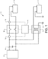
- a contactor control system comprising a switching member, a high voltage load, a high voltage energy storage, a bi-directional DC/DC-converter operatively connected to the switching member, a high-voltage capacitor operatively connected to the high-voltage load, and a low voltage energy storage operatively connected to the bi-directional DC/DC-converter, wherein the switching member is adapted to connect and disconnect the high voltage energy storage to and from the high voltage load
- the object of the invention is achieved in that the bi-directional DC/DC-converter is adapted to pre-charge the high-voltage capacitor to a predefined voltage value from the low voltage energy storage before the switching member is closed and adapted to discharge the high-voltage capacitor to the low voltage energy storage when the switching member has been opened.
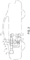
- Fig. 2 shows a vehicle 30 comprising a switch control system 1 according to the invention.
- the switch control system may be positioned at any suitable place in the vehicle, but is preferably arranged close to the high-voltage energy storage or the high voltage load in order to minimize the cable length of the high voltage cables. Both the high side and the low side of the high voltage require a separate cable.
- the low voltage system is provided with a ground connection 9.
Landscapes
- Engineering & Computer Science (AREA)
- Power Engineering (AREA)
- Life Sciences & Earth Sciences (AREA)
- Sustainable Development (AREA)
- Sustainable Energy (AREA)
- Transportation (AREA)
- Mechanical Engineering (AREA)
- Electric Propulsion And Braking For Vehicles (AREA)
- Dc-Dc Converters (AREA)
- Charge And Discharge Circuits For Batteries Or The Like (AREA)
Claims (13)
- Schaltsteuerungssystem (1) umfassend ein Schaltglied (10), eine Hochspannungslast (4), einen Hochspannungsenergiespeicher (2), einen mit dem Schaltglied (10) wirkverbundenen bidirektionalen DC/DC-Wandler (5), einen mit der Hochspannungslast (4) wirkverbundenen Hochspannungskondensator (6) und einen mit dem bidirektionalen DC/DC-Wandler (5) wirkverbundenen Niederspannungsenergiespeicher (3), wobei das Schaltglied (10) zum Verbinden und Trennen des Hochspannungsenergiespeichers (2) zu und von der Hochspannungslast (4) ausgelegt ist, dadurch gekennzeichnet, dass der bidirektionale DC/DC-Wandler (5) zum Vorladen des Hochspannungskondensators (6) auf einen vorgegebenen Spannungswert aus dem Niederspannungsenergiespeicher (3) ausgelegt ist, bevor das Schaltglied (10) geschlossen wird, und zum Entladen des Hochspannungskondensators (6) zum Niederspannungsenergiespeicher (3) ausgelegt ist, wenn das Schaltglied (10) geöffnet wurde, und wobei der vorgegebene Spannungswert so eingestellt ist, dass er zwischen einem Spannungswert, der manchmal niedriger als die Spannung des Hochspannungsenergiespeichers ist und der manchmal höher als die Spannung des Hochspannungsenergiespeichers ist, wechselt.
- Schaltsteuerungssystem nach Anspruch 1, dadurch gekennzeichnet, dass das System einen mit einer ersten Seite des Schaltglieds (10) wirkverbundenen ersten Spannungssensor (12) und einen mit einer zweiten Seite des Schaltglieds (10) wirkverbundenen zweiten Spannungssensor (13) umfasst.
- Schaltsteuerungssystem nach Anspruch 2, dadurch gekennzeichnet, dass das System eine Steuereinheit (11) umfasst, die zum Empfangen von Spannungswerten aus dem ersten Spannungssensor (12) und dem zweiten Spannungssensor (13) angepasst ist, um den vorgegebenen Spannungswert zu bestimmen, und um das Schaltglied (10) in Abhängigkeit des bestimmten vorgegebenen Spannungswertes zu steuern.
- Schaltsteuerungssystem nach einem der Ansprüche 1 bis 3, dadurch gekennzeichnet, dass der vorgegebene Spannungswert von der Spannung des Hochspannungsenergiespeichers (2) abhängig ist.
- Schaltsteuerungssystem nach einem der Ansprüche 1 bis 4, dadurch gekennzeichnet, dass der vorgegebene Spannungswert von der Spannung des Hochspannungsenergiespeichers (2) um weniger als 1 % abweicht.
- Schaltsteuerungssystem nach einem der Ansprüche 1 bis 4, dadurch gekennzeichnet, dass der vorgegebene Spannungswert höher als die Spannung des Niederspannungsenergiespeichers (3) ist.
- Schaltsteuerungssystem nach einem der Ansprüche 1 bis 6, dadurch gekennzeichnet, dass der Niederspannungsenergiespeicher (3) aus einer ersten Bleibatterie und einem zweiten unterschiedlichen Niederspannungsenergiespeicher besteht.
- Fahrzeug, wobei das Fahrzeug (30) ein Schaltsteuerungssystem (1) nach einem der vorhergehenden Ansprüche umfasst.
- Fahrzeug nach Anspruch 8, wobei es sich beim Fahrzeug (1) um ein Hybridfahrzeug handelt.
- Verfahren zum Laden und Entladen eines Hochspannungskondensators (6) in einem Fahrzeug umfassend eine Hochspannungslast (4) mit einem Hochspannungskondensator (6) und einen Hochspannungsenergiespeicher (2), umfassend die folgenden Schritte:- Vorladen des Hochspannungskondensators auf einen vorgegebenen Spannungswert mit einem bidirektionalen DC/DC-Wandler (5) aus einem Niederspannungsenergiespeicher (3) vor dem Starten des Fahrzeugs,- Verbinden des Hochspannungsenergiespeichers mit der Hochspannungslast mit einem Schaltglied (10), wenn die Spannungsdifferenz zwischen der Eingangsseite und der Ausgangsseite des Schaltglieds unter einem vorgegebenen Wert liegt,- Trennen des Hochspannungsenergiespeichers von der Hochspannungslast nach dem Stoppen des Fahrzeugs,- Entladen des Hochspannungskondensators mit dem bidirektionalen DC/DC-Wandler zum Niederspannungsenergiespeicher,wobei der vorgegebene Spannungswert höher als die Spannung des Hochspannungsenergiespeichers zu einem Startzeitpunkt des Fahrzeugs ist, und dass der vorgegebene Spannungswert niedriger als die Spannung des Hochspannungsenergiespeichers zu einem anderen Startzeitpunkt des Fahrzeugs ist.
- Verfahren nach Anspruch 10, umfassend den zusätzlichen Schritt: Abwarten eines vorgegebenen Zeitintervalls vor dem Entladen des Hochspannungskondensators mit dem bidirektionalen DC/DC-Wandler.
- Computerprogramm, das Programmcodemittel zur Durchführung aller Schritte nach den Ansprüchen 10 oder 11 umfasst, wenn das Programm auf einem Computer läuft.
- Computerprogrammprodukt, das Programmcodemittel umfasst, die auf einem computerlesbaren Medium zur Durchführung aller Schritte nach den Ansprüchen 10 oder 11 gespeichert sind, wenn das Programmprodukt auf einem Computer läuft.
Priority Applications (4)
| Application Number | Priority Date | Filing Date | Title |
|---|---|---|---|
| EP17201270.0A EP3482994B1 (de) | 2017-11-13 | 2017-11-13 | Schützsteuerungssystem und verfahren zur steuerung eines schütz |
| PCT/CN2018/114892 WO2019091465A1 (en) | 2017-11-13 | 2018-11-09 | Contactor control system and method for controlling a contactor |
| CN201880072573.1A CN111315610B (zh) | 2017-11-13 | 2018-11-09 | 接触器控制系统和用于控制接触器的方法 |
| US16/872,887 US11878603B2 (en) | 2017-11-13 | 2020-05-12 | Contactor control system and method for controlling a contactor |
Applications Claiming Priority (1)
| Application Number | Priority Date | Filing Date | Title |
|---|---|---|---|
| EP17201270.0A EP3482994B1 (de) | 2017-11-13 | 2017-11-13 | Schützsteuerungssystem und verfahren zur steuerung eines schütz |
Publications (2)
| Publication Number | Publication Date |
|---|---|
| EP3482994A1 EP3482994A1 (de) | 2019-05-15 |
| EP3482994B1 true EP3482994B1 (de) | 2020-07-22 |
Family
ID=60327110
Family Applications (1)
| Application Number | Title | Priority Date | Filing Date |
|---|---|---|---|
| EP17201270.0A Active EP3482994B1 (de) | 2017-11-13 | 2017-11-13 | Schützsteuerungssystem und verfahren zur steuerung eines schütz |
Country Status (4)
| Country | Link |
|---|---|
| US (1) | US11878603B2 (de) |
| EP (1) | EP3482994B1 (de) |
| CN (1) | CN111315610B (de) |
| WO (1) | WO2019091465A1 (de) |
Families Citing this family (9)
| Publication number | Priority date | Publication date | Assignee | Title |
|---|---|---|---|---|
| CN113022466A (zh) * | 2019-12-05 | 2021-06-25 | 观致汽车有限公司 | 电动汽车及其控制方法和装置 |
| WO2021199118A1 (ja) * | 2020-03-30 | 2021-10-07 | 三菱電機株式会社 | エレベーター |
| CN111660871A (zh) * | 2020-05-15 | 2020-09-15 | 浙江飞碟汽车制造有限公司 | 一种新能源汽车的新型电源供电系统及其供电方法 |
| FR3114930B1 (fr) * | 2020-10-02 | 2022-10-28 | Safran Electrical & Power | Système de génération d’énergie électrique pour alimenter une charge d’un aéronef et utilisation d’un tel système |
| US12128774B2 (en) | 2022-06-23 | 2024-10-29 | Ford Global Technologies, Llc | Electrified vehicle high voltage contactor control |
| CN115071430A (zh) * | 2022-08-23 | 2022-09-20 | 江苏智能无人装备产业创新中心有限公司 | 一种基于双向电源的预充继电器冗余控制方法及装置 |
| US12401290B2 (en) | 2022-12-22 | 2025-08-26 | Lear Corporation | DC-to-DC converter and method for controlling same |
| US12587025B2 (en) * | 2023-12-12 | 2026-03-24 | Industrial Technology Research Institute | Electrical coupling circuit and method thereof |
| CN117818356A (zh) * | 2023-12-20 | 2024-04-05 | 蔚来汽车科技(安徽)有限公司 | 电动汽车的电气系统和用于控制上电、下电过程的方法 |
Family Cites Families (15)
| Publication number | Priority date | Publication date | Assignee | Title |
|---|---|---|---|---|
| US5440180A (en) * | 1992-09-28 | 1995-08-08 | Eaton Corporation | Microprocessor based electrical contactor with distributed contactor opening |
| JP3886733B2 (ja) * | 2001-04-03 | 2007-02-28 | 矢崎総業株式会社 | 車両用電源装置 |
| JP3625789B2 (ja) * | 2001-08-10 | 2005-03-02 | 本田技研工業株式会社 | 車両の電源装置 |
| JP2007318849A (ja) * | 2006-05-24 | 2007-12-06 | Toyota Motor Corp | 電気自動車の電気システム |
| JP5831760B2 (ja) * | 2012-04-05 | 2015-12-09 | 株式会社デンソー | 電源制御システムの異常診断装置 |
| US9925878B2 (en) * | 2013-09-26 | 2018-03-27 | Ford Global Technologies, Llc | Bus pre-charge control using a buck converter |
| DE102013225884A1 (de) | 2013-12-13 | 2015-06-18 | Volkswagen Aktiengesellschaft | Vorladen eines elektrischen Zwischenkreisspeichers |
| EP3110652B1 (de) * | 2014-02-24 | 2017-12-20 | Volvo Truck Corporation | Elektrisches speichersystem für fahrzeug und verfahren zu dessen steuerung |
| US9413184B2 (en) | 2014-03-21 | 2016-08-09 | Lg Chem, Ltd. | Pre-charging and voltage supply system for a DC-AC inverter |
| KR102302783B1 (ko) | 2014-07-25 | 2021-09-16 | 현대모비스 주식회사 | 차량 구동 시스템 및 방법 |
| JP6201967B2 (ja) | 2014-11-26 | 2017-09-27 | トヨタ自動車株式会社 | 電気自動車 |
| US10232735B2 (en) * | 2015-10-22 | 2019-03-19 | Denso Corporation | Control device for power supply system |
| CN107554335B (zh) * | 2017-08-30 | 2020-02-18 | 奇瑞新能源汽车技术有限公司 | 车载电力系统和汽车 |
| CN207339369U (zh) * | 2017-10-31 | 2018-05-08 | 北京新能源汽车股份有限公司 | 一种充电电路及电动汽车 |
| CN108422889A (zh) * | 2018-04-28 | 2018-08-21 | 东南(福建)汽车工业有限公司 | 一种电动汽车用的预充控制电路及控制方法 |
-
2017
- 2017-11-13 EP EP17201270.0A patent/EP3482994B1/de active Active
-
2018
- 2018-11-09 WO PCT/CN2018/114892 patent/WO2019091465A1/en not_active Ceased
- 2018-11-09 CN CN201880072573.1A patent/CN111315610B/zh active Active
-
2020
- 2020-05-12 US US16/872,887 patent/US11878603B2/en active Active
Non-Patent Citations (1)
| Title |
|---|
| None * |
Also Published As
| Publication number | Publication date |
|---|---|
| CN111315610B (zh) | 2021-12-17 |
| WO2019091465A1 (en) | 2019-05-16 |
| US20200269718A1 (en) | 2020-08-27 |
| US11878603B2 (en) | 2024-01-23 |
| CN111315610A (zh) | 2020-06-19 |
| EP3482994A1 (de) | 2019-05-15 |
Similar Documents
| Publication | Publication Date | Title |
|---|---|---|
| US11878603B2 (en) | Contactor control system and method for controlling a contactor | |
| EP3046198B1 (de) | Elektrisches energiespeichersystem | |
| US10160325B2 (en) | Vehicle power control method and system for jump-start | |
| CA2860940C (en) | System and method for high voltage cable detection in hybrid vehicles | |
| US9002558B2 (en) | Abnormality diagnosis apparatus for power control system | |
| US7806095B2 (en) | Vehicle starting assist system | |
| US10131298B2 (en) | Controlled connection of multiple wiring system branches of a vehicle | |
| CN102205788B (zh) | 用于混合动力车辆的蓄电池充电系统 | |
| RU2688930C2 (ru) | Устройство и способ управления зарядкой и разрядкой суперконденсаторов | |
| CN102343877A (zh) | 低压总线稳定性 | |
| KR101866063B1 (ko) | 보조배터리의 릴레이 제어 시스템 및 그 방법 | |
| CN105934860A (zh) | 用于运行车载电网的方法 | |
| EP3425766B1 (de) | Kondensatormodul | |
| KR20140068556A (ko) | 전기자동차용 직류 변환장치의 제어방법 | |
| KR20070020695A (ko) | 하이브리드 전기 자동차의 돌입전류 방지장치 | |
| CN110654251B (zh) | 用于给牵引电网中的高压电池组充电的方法和牵引电网 | |
| KR102336964B1 (ko) | 마일드 하이브리드 자동차의 배터리 및 배터리 제어 방법 | |
| CN108879813B (zh) | 接近检测装置及方法 | |
| US20170305414A1 (en) | Hybrid vehicle | |
| US20170130689A1 (en) | Ignition apparatus and ignition control method | |
| KR20200121412A (ko) | 차량 시스템 및 그 제어 방법 |
Legal Events
| Date | Code | Title | Description |
|---|---|---|---|
| PUAI | Public reference made under article 153(3) epc to a published international application that has entered the european phase |
Free format text: ORIGINAL CODE: 0009012 |
|
| STAA | Information on the status of an ep patent application or granted ep patent |
Free format text: STATUS: REQUEST FOR EXAMINATION WAS MADE |
|
| 17P | Request for examination filed |
Effective date: 20171113 |
|
| AK | Designated contracting states |
Kind code of ref document: A1 Designated state(s): AL AT BE BG CH CY CZ DE DK EE ES FI FR GB GR HR HU IE IS IT LI LT LU LV MC MK MT NL NO PL PT RO RS SE SI SK SM TR |
|
| AX | Request for extension of the european patent |
Extension state: BA ME |
|
| GRAP | Despatch of communication of intention to grant a patent |
Free format text: ORIGINAL CODE: EPIDOSNIGR1 |
|
| STAA | Information on the status of an ep patent application or granted ep patent |
Free format text: STATUS: GRANT OF PATENT IS INTENDED |
|
| RAP1 | Party data changed (applicant data changed or rights of an application transferred) |
Owner name: NINGBO GEELY AUTOMOBILE RESEARCH & DEVELOPMENT CO., LTD. |
|
| INTG | Intention to grant announced |
Effective date: 20200324 |
|
| GRAS | Grant fee paid |
Free format text: ORIGINAL CODE: EPIDOSNIGR3 |
|
| GRAA | (expected) grant |
Free format text: ORIGINAL CODE: 0009210 |
|
| STAA | Information on the status of an ep patent application or granted ep patent |
Free format text: STATUS: THE PATENT HAS BEEN GRANTED |
|
| AK | Designated contracting states |
Kind code of ref document: B1 Designated state(s): AL AT BE BG CH CY CZ DE DK EE ES FI FR GB GR HR HU IE IS IT LI LT LU LV MC MK MT NL NO PL PT RO RS SE SI SK SM TR |
|
| REG | Reference to a national code |
Ref country code: GB Ref legal event code: FG4D |
|
| REG | Reference to a national code |
Ref country code: CH Ref legal event code: EP |
|
| REG | Reference to a national code |
Ref country code: DE Ref legal event code: R096 Ref document number: 602017020105 Country of ref document: DE |
|
| REG | Reference to a national code |
Ref country code: AT Ref legal event code: REF Ref document number: 1293080 Country of ref document: AT Kind code of ref document: T Effective date: 20200815 |
|
| REG | Reference to a national code |
Ref country code: IE Ref legal event code: FG4D |
|
| REG | Reference to a national code |
Ref country code: LT Ref legal event code: MG4D |
|
| REG | Reference to a national code |
Ref country code: AT Ref legal event code: MK05 Ref document number: 1293080 Country of ref document: AT Kind code of ref document: T Effective date: 20200722 |
|
| PG25 | Lapsed in a contracting state [announced via postgrant information from national office to epo] |
Ref country code: FI Free format text: LAPSE BECAUSE OF FAILURE TO SUBMIT A TRANSLATION OF THE DESCRIPTION OR TO PAY THE FEE WITHIN THE PRESCRIBED TIME-LIMIT Effective date: 20200722 Ref country code: AT Free format text: LAPSE BECAUSE OF FAILURE TO SUBMIT A TRANSLATION OF THE DESCRIPTION OR TO PAY THE FEE WITHIN THE PRESCRIBED TIME-LIMIT Effective date: 20200722 Ref country code: NO Free format text: LAPSE BECAUSE OF FAILURE TO SUBMIT A TRANSLATION OF THE DESCRIPTION OR TO PAY THE FEE WITHIN THE PRESCRIBED TIME-LIMIT Effective date: 20201022 Ref country code: GR Free format text: LAPSE BECAUSE OF FAILURE TO SUBMIT A TRANSLATION OF THE DESCRIPTION OR TO PAY THE FEE WITHIN THE PRESCRIBED TIME-LIMIT Effective date: 20201023 Ref country code: ES Free format text: LAPSE BECAUSE OF FAILURE TO SUBMIT A TRANSLATION OF THE DESCRIPTION OR TO PAY THE FEE WITHIN THE PRESCRIBED TIME-LIMIT Effective date: 20200722 Ref country code: SE Free format text: LAPSE BECAUSE OF FAILURE TO SUBMIT A TRANSLATION OF THE DESCRIPTION OR TO PAY THE FEE WITHIN THE PRESCRIBED TIME-LIMIT Effective date: 20200722 Ref country code: BG Free format text: LAPSE BECAUSE OF FAILURE TO SUBMIT A TRANSLATION OF THE DESCRIPTION OR TO PAY THE FEE WITHIN THE PRESCRIBED TIME-LIMIT Effective date: 20201022 Ref country code: PT Free format text: LAPSE BECAUSE OF FAILURE TO SUBMIT A TRANSLATION OF THE DESCRIPTION OR TO PAY THE FEE WITHIN THE PRESCRIBED TIME-LIMIT Effective date: 20201123 Ref country code: HR Free format text: LAPSE BECAUSE OF FAILURE TO SUBMIT A TRANSLATION OF THE DESCRIPTION OR TO PAY THE FEE WITHIN THE PRESCRIBED TIME-LIMIT Effective date: 20200722 Ref country code: LT Free format text: LAPSE BECAUSE OF FAILURE TO SUBMIT A TRANSLATION OF THE DESCRIPTION OR TO PAY THE FEE WITHIN THE PRESCRIBED TIME-LIMIT Effective date: 20200722 |
|
| PG25 | Lapsed in a contracting state [announced via postgrant information from national office to epo] |
Ref country code: RS Free format text: LAPSE BECAUSE OF FAILURE TO SUBMIT A TRANSLATION OF THE DESCRIPTION OR TO PAY THE FEE WITHIN THE PRESCRIBED TIME-LIMIT Effective date: 20200722 Ref country code: LV Free format text: LAPSE BECAUSE OF FAILURE TO SUBMIT A TRANSLATION OF THE DESCRIPTION OR TO PAY THE FEE WITHIN THE PRESCRIBED TIME-LIMIT Effective date: 20200722 Ref country code: PL Free format text: LAPSE BECAUSE OF FAILURE TO SUBMIT A TRANSLATION OF THE DESCRIPTION OR TO PAY THE FEE WITHIN THE PRESCRIBED TIME-LIMIT Effective date: 20200722 Ref country code: IS Free format text: LAPSE BECAUSE OF FAILURE TO SUBMIT A TRANSLATION OF THE DESCRIPTION OR TO PAY THE FEE WITHIN THE PRESCRIBED TIME-LIMIT Effective date: 20201122 |
|
| PG25 | Lapsed in a contracting state [announced via postgrant information from national office to epo] |
Ref country code: NL Free format text: LAPSE BECAUSE OF FAILURE TO SUBMIT A TRANSLATION OF THE DESCRIPTION OR TO PAY THE FEE WITHIN THE PRESCRIBED TIME-LIMIT Effective date: 20200722 |
|
| REG | Reference to a national code |
Ref country code: DE Ref legal event code: R097 Ref document number: 602017020105 Country of ref document: DE |
|
| PG25 | Lapsed in a contracting state [announced via postgrant information from national office to epo] |
Ref country code: RO Free format text: LAPSE BECAUSE OF FAILURE TO SUBMIT A TRANSLATION OF THE DESCRIPTION OR TO PAY THE FEE WITHIN THE PRESCRIBED TIME-LIMIT Effective date: 20200722 Ref country code: CZ Free format text: LAPSE BECAUSE OF FAILURE TO SUBMIT A TRANSLATION OF THE DESCRIPTION OR TO PAY THE FEE WITHIN THE PRESCRIBED TIME-LIMIT Effective date: 20200722 Ref country code: DK Free format text: LAPSE BECAUSE OF FAILURE TO SUBMIT A TRANSLATION OF THE DESCRIPTION OR TO PAY THE FEE WITHIN THE PRESCRIBED TIME-LIMIT Effective date: 20200722 Ref country code: SM Free format text: LAPSE BECAUSE OF FAILURE TO SUBMIT A TRANSLATION OF THE DESCRIPTION OR TO PAY THE FEE WITHIN THE PRESCRIBED TIME-LIMIT Effective date: 20200722 Ref country code: EE Free format text: LAPSE BECAUSE OF FAILURE TO SUBMIT A TRANSLATION OF THE DESCRIPTION OR TO PAY THE FEE WITHIN THE PRESCRIBED TIME-LIMIT Effective date: 20200722 Ref country code: IT Free format text: LAPSE BECAUSE OF FAILURE TO SUBMIT A TRANSLATION OF THE DESCRIPTION OR TO PAY THE FEE WITHIN THE PRESCRIBED TIME-LIMIT Effective date: 20200722 |
|
| PLBE | No opposition filed within time limit |
Free format text: ORIGINAL CODE: 0009261 |
|
| STAA | Information on the status of an ep patent application or granted ep patent |
Free format text: STATUS: NO OPPOSITION FILED WITHIN TIME LIMIT |
|
| PG25 | Lapsed in a contracting state [announced via postgrant information from national office to epo] |
Ref country code: AL Free format text: LAPSE BECAUSE OF FAILURE TO SUBMIT A TRANSLATION OF THE DESCRIPTION OR TO PAY THE FEE WITHIN THE PRESCRIBED TIME-LIMIT Effective date: 20200722 |
|
| 26N | No opposition filed |
Effective date: 20210423 |
|
| PG25 | Lapsed in a contracting state [announced via postgrant information from national office to epo] |
Ref country code: MC Free format text: LAPSE BECAUSE OF FAILURE TO SUBMIT A TRANSLATION OF THE DESCRIPTION OR TO PAY THE FEE WITHIN THE PRESCRIBED TIME-LIMIT Effective date: 20200722 Ref country code: SK Free format text: LAPSE BECAUSE OF FAILURE TO SUBMIT A TRANSLATION OF THE DESCRIPTION OR TO PAY THE FEE WITHIN THE PRESCRIBED TIME-LIMIT Effective date: 20200722 |
|
| REG | Reference to a national code |
Ref country code: CH Ref legal event code: PL |
|
| PG25 | Lapsed in a contracting state [announced via postgrant information from national office to epo] |
Ref country code: LU Free format text: LAPSE BECAUSE OF NON-PAYMENT OF DUE FEES Effective date: 20201113 |
|
| REG | Reference to a national code |
Ref country code: BE Ref legal event code: MM Effective date: 20201130 |
|
| PG25 | Lapsed in a contracting state [announced via postgrant information from national office to epo] |
Ref country code: SI Free format text: LAPSE BECAUSE OF FAILURE TO SUBMIT A TRANSLATION OF THE DESCRIPTION OR TO PAY THE FEE WITHIN THE PRESCRIBED TIME-LIMIT Effective date: 20200722 Ref country code: LI Free format text: LAPSE BECAUSE OF NON-PAYMENT OF DUE FEES Effective date: 20201130 Ref country code: CH Free format text: LAPSE BECAUSE OF NON-PAYMENT OF DUE FEES Effective date: 20201130 |
|
| REG | Reference to a national code |
Ref country code: NL Ref legal event code: MP Effective date: 20200722 |
|
| PG25 | Lapsed in a contracting state [announced via postgrant information from national office to epo] |
Ref country code: IE Free format text: LAPSE BECAUSE OF NON-PAYMENT OF DUE FEES Effective date: 20201113 |
|
| PG25 | Lapsed in a contracting state [announced via postgrant information from national office to epo] |
Ref country code: TR Free format text: LAPSE BECAUSE OF FAILURE TO SUBMIT A TRANSLATION OF THE DESCRIPTION OR TO PAY THE FEE WITHIN THE PRESCRIBED TIME-LIMIT Effective date: 20200722 Ref country code: MT Free format text: LAPSE BECAUSE OF FAILURE TO SUBMIT A TRANSLATION OF THE DESCRIPTION OR TO PAY THE FEE WITHIN THE PRESCRIBED TIME-LIMIT Effective date: 20200722 Ref country code: CY Free format text: LAPSE BECAUSE OF FAILURE TO SUBMIT A TRANSLATION OF THE DESCRIPTION OR TO PAY THE FEE WITHIN THE PRESCRIBED TIME-LIMIT Effective date: 20200722 |
|
| PG25 | Lapsed in a contracting state [announced via postgrant information from national office to epo] |
Ref country code: MK Free format text: LAPSE BECAUSE OF FAILURE TO SUBMIT A TRANSLATION OF THE DESCRIPTION OR TO PAY THE FEE WITHIN THE PRESCRIBED TIME-LIMIT Effective date: 20200722 |
|
| PG25 | Lapsed in a contracting state [announced via postgrant information from national office to epo] |
Ref country code: BE Free format text: LAPSE BECAUSE OF NON-PAYMENT OF DUE FEES Effective date: 20201130 |
|
| PGFP | Annual fee paid to national office [announced via postgrant information from national office to epo] |
Ref country code: DE Payment date: 20251118 Year of fee payment: 9 |
|
| PGFP | Annual fee paid to national office [announced via postgrant information from national office to epo] |
Ref country code: GB Payment date: 20251020 Year of fee payment: 9 |
|
| PGFP | Annual fee paid to national office [announced via postgrant information from national office to epo] |
Ref country code: FR Payment date: 20251020 Year of fee payment: 9 |