EP3483005A1 - Procédé et système d'éclairage destinés à la protection contre la lumière éblouissante ainsi que machine de travail pourvue d'un tel système d'éclairage - Google Patents
Procédé et système d'éclairage destinés à la protection contre la lumière éblouissante ainsi que machine de travail pourvue d'un tel système d'éclairage Download PDFInfo
- Publication number
- EP3483005A1 EP3483005A1 EP18205368.6A EP18205368A EP3483005A1 EP 3483005 A1 EP3483005 A1 EP 3483005A1 EP 18205368 A EP18205368 A EP 18205368A EP 3483005 A1 EP3483005 A1 EP 3483005A1
- Authority
- EP
- European Patent Office
- Prior art keywords
- light
- coding
- glare
- lighting
- lighting system
- Prior art date
- Legal status (The legal status is an assumption and is not a legal conclusion. Google has not performed a legal analysis and makes no representation as to the accuracy of the status listed.)
- Granted
Links
Images
Classifications
-
- H—ELECTRICITY
- H05—ELECTRIC TECHNIQUES NOT OTHERWISE PROVIDED FOR
- H05B—ELECTRIC HEATING; ELECTRIC LIGHT SOURCES NOT OTHERWISE PROVIDED FOR; CIRCUIT ARRANGEMENTS FOR ELECTRIC LIGHT SOURCES, IN GENERAL
- H05B45/00—Circuit arrangements for operating light-emitting diodes [LED]
- H05B45/10—Controlling the intensity of the light
- H05B45/12—Controlling the intensity of the light using optical feedback
-
- B—PERFORMING OPERATIONS; TRANSPORTING
- B60—VEHICLES IN GENERAL
- B60Q—ARRANGEMENT OF SIGNALLING OR LIGHTING DEVICES, THE MOUNTING OR SUPPORTING THEREOF OR CIRCUITS THEREFOR, FOR VEHICLES IN GENERAL
- B60Q1/00—Arrangement of optical signalling or lighting devices, the mounting or supporting thereof or circuits therefor
- B60Q1/02—Arrangement of optical signalling or lighting devices, the mounting or supporting thereof or circuits therefor the devices being primarily intended to illuminate the way ahead or to illuminate other areas of way or environments
- B60Q1/04—Arrangement of optical signalling or lighting devices, the mounting or supporting thereof or circuits therefor the devices being primarily intended to illuminate the way ahead or to illuminate other areas of way or environments the devices being headlights
- B60Q1/14—Arrangement of optical signalling or lighting devices, the mounting or supporting thereof or circuits therefor the devices being primarily intended to illuminate the way ahead or to illuminate other areas of way or environments the devices being headlights having dimming means
- B60Q1/1415—Dimming circuits
- B60Q1/1423—Automatic dimming circuits, i.e. switching between high beam and low beam due to change of ambient light or light level in road traffic
- B60Q1/143—Automatic dimming circuits, i.e. switching between high beam and low beam due to change of ambient light or light level in road traffic combined with another condition, e.g. using vehicle recognition from camera images or activation of wipers
-
- B—PERFORMING OPERATIONS; TRANSPORTING
- B60—VEHICLES IN GENERAL
- B60Q—ARRANGEMENT OF SIGNALLING OR LIGHTING DEVICES, THE MOUNTING OR SUPPORTING THEREOF OR CIRCUITS THEREFOR, FOR VEHICLES IN GENERAL
- B60Q3/00—Arrangement of lighting devices for vehicle interiors; Lighting devices specially adapted for vehicle interiors
- B60Q3/80—Circuits; Control arrangements
-
- B—PERFORMING OPERATIONS; TRANSPORTING
- B60—VEHICLES IN GENERAL
- B60Q—ARRANGEMENT OF SIGNALLING OR LIGHTING DEVICES, THE MOUNTING OR SUPPORTING THEREOF OR CIRCUITS THEREFOR, FOR VEHICLES IN GENERAL
- B60Q2300/00—Indexing codes for automatically adjustable headlamps or automatically dimmable headlamps
- B60Q2300/20—Indexing codes relating to the driver or the passengers
- B60Q2300/23—Driver's line of sight
-
- B—PERFORMING OPERATIONS; TRANSPORTING
- B60—VEHICLES IN GENERAL
- B60Q—ARRANGEMENT OF SIGNALLING OR LIGHTING DEVICES, THE MOUNTING OR SUPPORTING THEREOF OR CIRCUITS THEREFOR, FOR VEHICLES IN GENERAL
- B60Q2300/00—Indexing codes for automatically adjustable headlamps or automatically dimmable headlamps
- B60Q2300/40—Indexing codes relating to other road users or special conditions
- B60Q2300/45—Special conditions, e.g. pedestrians, road signs or potential dangers
-
- B—PERFORMING OPERATIONS; TRANSPORTING
- B60—VEHICLES IN GENERAL
- B60Q—ARRANGEMENT OF SIGNALLING OR LIGHTING DEVICES, THE MOUNTING OR SUPPORTING THEREOF OR CIRCUITS THEREFOR, FOR VEHICLES IN GENERAL
- B60Q2800/00—Features related to particular types of vehicles not otherwise provided for
- B60Q2800/20—Utility vehicles, e.g. for agriculture, construction work
-
- Y—GENERAL TAGGING OF NEW TECHNOLOGICAL DEVELOPMENTS; GENERAL TAGGING OF CROSS-SECTIONAL TECHNOLOGIES SPANNING OVER SEVERAL SECTIONS OF THE IPC; TECHNICAL SUBJECTS COVERED BY FORMER USPC CROSS-REFERENCE ART COLLECTIONS [XRACs] AND DIGESTS
- Y02—TECHNOLOGIES OR APPLICATIONS FOR MITIGATION OR ADAPTATION AGAINST CLIMATE CHANGE
- Y02B—CLIMATE CHANGE MITIGATION TECHNOLOGIES RELATED TO BUILDINGS, e.g. HOUSING, HOUSE APPLIANCES OR RELATED END-USER APPLICATIONS
- Y02B20/00—Energy efficient lighting technologies, e.g. halogen lamps or gas discharge lamps
- Y02B20/30—Semiconductor lamps, e.g. solid state lamps [SSL] light emitting diodes [LED] or organic LED [OLED]
Definitions
- the present invention relates to a method for protecting a user of a lighting system from glare from at least one light source of the lighting system.
- the invention further relates to a lighting system for carrying out such a method and to a working machine with the lighting system.
- One or more headlights of a vehicle may have an integrated light sensor. Such a light sensor responds to reflected light.
- the light sensor can be active or passive.
- An active light sensor generates an electrical quantity by the incident light.
- a passive light sensor changes its internal electrical properties as a function of the incident light.
- the active or passive change of the light sensor is interpreted analog and / or digital and has an impact on the power to the headlight. By increasing or decreasing the current as a function of a light sensor signal, the light intensity is automatically adapted to the reflected light.
- the perceived as unpleasant threshold or Setpoint value to be dimmed from that depends on the purpose and can be adjusted by changing the circuit parameters.
- an external self-glare protection system detects whether or not light is reflected back to a driver of a work machine with the auto glare protection system.
- External light sensors can be placed independently of the headlight. In the case of external self-glare protection systems, additional data transmission between light sensors and headlamps must be provided. For this purpose, the light sensor can be placed closer to the driver's eye in the case of external self-glare protection systems. The closer the light sensor is positioned to the driver's eye, the more effectively glare of the driver can be detected.
- Object of the present invention is to at least partially take into account the problem described above.
- each light of each light source receives a different coding, it can be detected reliably and quickly when the glare light is detected, from which light source or from which light sources the glare light or the glare lights originate. Subsequently, the detected glare can be responded to quickly by the respective glare source is set as desired.
- the glare source or the corresponding light source can in Dimming the frame, off and / or adjusted in position, so for example, rotated or moved.
- One or more encoding units may be used to create the encoding. Accordingly, it is possible that each lamp is assigned its own coding unit.
- the detected glare can be compared with a desired value or a desired luminous intensity. That is, glare is to be understood to mean light that has a light intensity above a predefined setpoint or threshold value. If it is determined that the glare light or the detected light is above the desired value, the light source or the light from the light source can be correspondingly adjusted, ie dimmed, switched off and / or changed with respect to its position.
- the lighting means are preferably arranged in the form of a light-emitting matrix in at least one lighting module for generating the working light.
- a matrix illumination enables a particularly fine adjustment of the work lighting with regard to a desired illumination as well as dimming.
- a matrix working light allows the explicit illumination of defined areas and can thus also be used effectively for glare protection by setting individual light sources or light pixels as desired.
- the lighting means as the smallest lighting unit of the lighting system can therefore be understood as light pixels of the light source matrix.
- the light-emitting matrix can have a plurality of rows of light and a plurality of light gaps, with a plurality of light sources being arranged in each light row and in each light column.
- the lighting system and correspondingly also the light-emitting matrix can therefore have at least four light-emitting means, which are arranged in at least two columns and at least two rows.
- the lighting system is preferably designed as a mobile lighting system.
- the lighting system is configured for mobile work, for example in and / or on a correspondingly mobile work machine.
- the lamps or the light-emitting means matrix or the lighting module is preceded by a converter, which can convert the coding into corresponding light signals.
- the converter or the converters is preferably preceded by a control unit for transmitting and / or generating the coding.
- the control unit can be designed in the form of a so-called light control unit (LCU).
- the LCU may also be configured and configured to evaluate the light signals detected by the at least one light sensor.
- the task of the LCU can alternatively or additionally be taken over by another control unit, such as a body control module (BCM), which can be in signal communication with the LCU.
- BCM body control module
- the individual light sources of the light module can be delimited from one another or slightly overlapping.
- the number of bulbs is basically freely selectable within technical limits. A reasonable number of bulbs can be selected depending on the purpose and mounting options.
- the fact that the at least one associated illuminant is adjusted on the basis of the detected glare light means that the at least one associated illuminant is set using the coding of the detected glare light.
- the detected glare can come from one or more bulbs.
- further signals and / or information can be used to set the at least one associated light source.
- the present invention relates to a lighting system in the form of work lighting for a work machine.
- work lighting differs in particular from the technical areas of the streets or Living room lighting.
- Such work lighting preferably has a brightness with which, for example, no street approval for a motor vehicle would be possible.
- the work lighting in question should be particularly suitable for mobile machines such as agricultural machinery.
- Agricultural machinery may be tractors, combine harvesters, harvesters, or the like.
- one of the lighting means and / or a lighting module for generating work light can be configured with at least 2,000 lumens. That is, the illuminant or light module is capable of producing work light with a luminous flux of at least 2,000 lumens. Furthermore, in the case of a lighting system according to the invention, it is possible to arrange a plurality of lighting means or lighting modules for generating work light, each with at least 2,000 lumens.
- the working light of the light system can be increased to, for example, 4,000 lumens, 6,000 lumens or even over 10,000 lumens.
- Such a luminous flux can decide in generic machines, especially in difficult weather and / or environmental conditions, whether the work can be done satisfactorily or not.
- the coding is carried out by means of pulse width modulation.
- Pulse width modulation has been found in experiments in the context of the present invention as a reliable method for creating the respective codes.
- the coding has a predefined duty cycle (duty cycle). That is, the coded light has the predefined duty cycle or is set with the predefined duty cycle.
- the duty cycle by which the light can be output as correspondingly pulsed light has also proved to be a simple and reliable means of coding.
- a duty cycle between 95% and 99%, in particular between 97% and 98%, is advantageous.
- a duty cycle of 97.5% has proven to be particularly advantageous. With such a duty cycle both a sufficient brightness can be achieved and a reliable and distinctive coding can be achieved.
- the coding has a predefined frequency. That is, each light source is driven at a different frequency or carrier frequency. This also allows a meaningful coding of the light accomplish.
- the respective codings preferably have different frequencies, the frequencies differing by at least 5 Hz, in particular in a range from 20 Hz to 30 Hz, preferably by approximately 30 Hz. That is, the different bulbs have lights with a corresponding frequency band spacing. Duty cycle and frequency band spacing of the pulse width modulation are in this case preferably set according to a sampling rate of the light sensor.
- a photodiode is preferably used and as a light source at least one LED.
- the frequency of the coding may have a rate between 100 Hz and 10,000 Hz, in particular between 1,000 Hz and 3,000 Hz. In particular, at a rate above 1,000 Hz, negative effects on a user of the lighting system can be prevented, which have been found at a lower frequency.
- the coding may also have a predefined bit coding. This also makes it possible to draw meaningful conclusions about the origin of the detected light or glare.
- a method to set the at least one associated illuminant using an eye-tracking system for capturing gaze information of a user of the lighting system and taking into account the acquired gaze information.
- the eye-tracking system the working light can be adjusted specifically to the needs of the user of the lighting system.
- a lighting system has a plurality of lighting means, at least one light sensor for detecting the lights of the lighting means, at least one coding unit for differently coding the lights of the lighting means, and a control unit for controlling the coding unit.
- the control unit is in signal communication with the at least one light sensor as well as the at least one coding unit and is designed to carry out a method as described in detail above.
- the coding unit can be configured in the form of a control unit, for example in the form of the LCU.
- the LCU may also be configured and configured to evaluate the light signals detected by the at least one light sensor.
- the task of the LCU can alternatively or additionally be taken over by another control unit, such as the BCM, which can be in signal communication with the LCU.
- the lighting means each have an LED or are each configured as an LED. LEDs have proven to be sufficiently bright and energy-saving bulbs.
- the at least one light sensor is arranged on or in the immediate vicinity of at least one of the lighting means.
- the lighting means can therefore have an integrated light sensor or light reference sensor.
- a plurality of light sources of the light system can each be equipped with a light sensor or at least one light sensor can be arranged in each case on a plurality of light sources. Due to the positioning of the light sensor on or in at least one of the light sources, the light system can be set specifically as desired, in particular with respect to third parties.
- an eye-tracking system for acquiring gaze information of a user of the lighting system, wherein the control unit is configured to set the at least one associated illuminant as a function of the acquired gaze information.
- the eye-tracking system can be designed in the form of a headset, which the user can put on like a kind of glasses. As a result, the eye movement of the user can be detected particularly accurately.
- the eye-tracking system can also be arranged decentrally by the user, for example in a driver's cab of a work machine in the field of vision of the user. As a result, the unrestricted freedom of movement and sight for the user can be guaranteed.
- a work machine having a lighting system as described above, the work machine having a booth for a user of the lighting system.
- a work machine according to the invention brings the advantages described above with it.
- the at least one light sensor is arranged in the cabin, in particular in the field of vision and at eye level of a user located and working in the cabin. This allows the user to be protected in a simple and reliable way from glare.
- the at least one light sensor is arranged in the cabin such that it is located near the eyes of the user, for example on average closer than 50 cm to the eyes of the user. It is assumed that a working position, in particular a sitting position, the user.
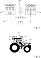
- Fig. 1 shows a lighting system 100 with a plurality of lamps L1 - L6 in the form of LEDs.
- the light system 100 comprises a light sensor 30 for detecting the lights M1-M6 of the light sources L1-L6 in the form of a photodiode, an encoding unit 40 for differently coding the lights M1-M6 of the light bulbs L1-L6, and a control unit 50 in the form of an LCU for Control the coding unit 40.
- the control unit 50 is in signal communication with the light sensor 30 and the coding unit 40 and is configured and configured to perform a method described in detail later.
- the LCU is preferably connected to a power source as well as to a BUS system for transmitting the desired modulation data.
- This in Fig. 1 illustrated lighting system has a first light emitting module 60 and a second light emitting module 70, wherein in the two light modules 60, 70 are each arranged three light sources.
- a first converter 10 for converting the coding for the light sources L1 - L3 is arranged
- a second converter 20 for converting the coding for the light bulbs L4-L6 is arranged in the first light-emitting module 60.
- the converters 10, 20 are each in signal connection with the coding unit 40. By means of the converters 10, 20, the pulse-width-modulated signal transmitted by the coding unit 40 can be converted into corresponding light signals at the light sources L1-L6.
- a method of protecting a user of the light system 100 from glare will be explained.
- the light M1 - M6 of the individual light sources L1 - L6 is first provided with a respective coding by the coding unit 40.
- the coding is carried out by means of pulse width modulation and has a predefined duty cycle of approximately 97.5% and a frequency of approximately 1000 Hz.
- the frequency band spacing of the respective frequencies is about 30 Hz.
- a predefined bit coding would also be possible.
- the coding unit 40 has a modulation module for the pulse width modulation for converting power into the desired pulsed signal.
- glare light M2X is detected by the light sensor 30.
- the light sensor 30 detects reflected light from the light source L2, which has a value that is too light at the light sensor 30, that is, exceeds a predefined setpoint value.
- Superimposed frequencies can be separated by a Fourier transformation of ambient light and from each other.
- a third step S3 the detected glare M2X is then assigned to the associated light source L2 on the basis of the coding of the light for the corresponding light source L2.
- a fourth step S4 the light source L2 is set to protect the user from the previously detected glare light M2X on the basis of the detected glare light M2X.
- the steps S2 to S4 can be repeated until there is no more glare.
- a work machine 200 in the form of a tractor with a lighting system 100 is shown.
- the light system 100 corresponds at least substantially to that described above with reference to FIG Fig. 1
- the work machine 200 has a booth 210 for a user of the lighting system 100.
- This in Fig. 2 shown light system 100 has two light sensors 30, wherein one of the light sensors 30 in the cabin 210 in the field of view and at eye level of a in the user 210 (not shown) is arranged and the other light sensor is arranged on the light module 70.
- the light system 100 further comprises an eye tracking system 80 for acquiring view information of the user of the light system 100, wherein the control unit 50 is configured to set the associated light source L2 as a function of detected visual information.
Landscapes
- Engineering & Computer Science (AREA)
- Mechanical Engineering (AREA)
- Circuit Arrangement For Electric Light Sources In General (AREA)
Applications Claiming Priority (1)
| Application Number | Priority Date | Filing Date | Title |
|---|---|---|---|
| DE102017220013.8A DE102017220013A1 (de) | 2017-11-10 | 2017-11-10 | Verfahren und Lichtsystem zum Schutz vor Blendlicht sowie Arbeitsmaschine mit dem Lichtsystem |
Publications (2)
| Publication Number | Publication Date |
|---|---|
| EP3483005A1 true EP3483005A1 (fr) | 2019-05-15 |
| EP3483005B1 EP3483005B1 (fr) | 2021-08-18 |
Family
ID=64331636
Family Applications (1)
| Application Number | Title | Priority Date | Filing Date |
|---|---|---|---|
| EP18205368.6A Active EP3483005B1 (fr) | 2017-11-10 | 2018-11-09 | Procédé et système d'éclairage destinés à la protection contre la lumière éblouissante ainsi que machine de travail pourvue d'un tel système d'éclairage |
Country Status (5)
| Country | Link |
|---|---|
| US (1) | US10485067B2 (fr) |
| EP (1) | EP3483005B1 (fr) |
| DE (1) | DE102017220013A1 (fr) |
| DK (1) | DK3483005T3 (fr) |
| MA (1) | MA46774A (fr) |
Families Citing this family (1)
| Publication number | Priority date | Publication date | Assignee | Title |
|---|---|---|---|---|
| DE102019108505A1 (de) * | 2019-04-02 | 2020-10-08 | Claas E-Systems Gmbh | Landwirtschaftliche Arbeitsmaschine |
Citations (5)
| Publication number | Priority date | Publication date | Assignee | Title |
|---|---|---|---|---|
| DE102007026750A1 (de) * | 2007-06-09 | 2009-01-08 | Volkswagen Ag | Verfahren und Vorrichtung zum automatischen Erfassen leuchtender Objekte im Straßenverkehr |
| US20140125234A1 (en) | 2012-11-02 | 2014-05-08 | Laurence P. Sadwick | Dimmer with Motion and Light Sensing |
| DE102013104276A1 (de) * | 2013-04-26 | 2014-10-30 | Hella Kgaa Hueck & Co. | Verfahren für die Anpassung wenigstens eines Ausleuchtparameters in einem lokalen Ausleuchtabschnitt eines Ausleuchtbereichs |
| DE102013104274A1 (de) * | 2013-04-26 | 2014-10-30 | Hella Kgaa Hueck & Co. | Verfahren für die Bestimmung des Eigenlichtanteils in Reflexionslicht |
| WO2017207185A1 (fr) * | 2016-05-30 | 2017-12-07 | Osram Gmbh | Procédé de réglage d'une distribution de lumière d'un dispositif d'éclairage, dispositif d'éclairage, dispositif de détection et véhicule |
Family Cites Families (3)
| Publication number | Priority date | Publication date | Assignee | Title |
|---|---|---|---|---|
| US8400061B2 (en) * | 2007-07-17 | 2013-03-19 | I/O Controls Corporation | Control network for LED-based lighting system in a transit vehicle |
| DE102010028406A1 (de) * | 2010-02-12 | 2011-08-18 | Osram Gesellschaft mit beschränkter Haftung, 81543 | LED-Leuchtvorrichtung und Verfahren zum Betreiben einer LED-Leuchtvorrichtung |
| WO2015026810A1 (fr) * | 2013-08-19 | 2015-02-26 | Gentex Corporation | Système d'imagerie de véhicule et procédé permettant de faire la distinction entre des objets réfléchissants et des lumières d'un autre véhicule |
-
2017
- 2017-11-10 DE DE102017220013.8A patent/DE102017220013A1/de not_active Withdrawn
-
2018
- 2018-11-05 US US16/180,516 patent/US10485067B2/en active Active
- 2018-11-09 DK DK18205368.6T patent/DK3483005T3/da active
- 2018-11-09 EP EP18205368.6A patent/EP3483005B1/fr active Active
- 2018-11-09 MA MA046774A patent/MA46774A/fr unknown
Patent Citations (5)
| Publication number | Priority date | Publication date | Assignee | Title |
|---|---|---|---|---|
| DE102007026750A1 (de) * | 2007-06-09 | 2009-01-08 | Volkswagen Ag | Verfahren und Vorrichtung zum automatischen Erfassen leuchtender Objekte im Straßenverkehr |
| US20140125234A1 (en) | 2012-11-02 | 2014-05-08 | Laurence P. Sadwick | Dimmer with Motion and Light Sensing |
| DE102013104276A1 (de) * | 2013-04-26 | 2014-10-30 | Hella Kgaa Hueck & Co. | Verfahren für die Anpassung wenigstens eines Ausleuchtparameters in einem lokalen Ausleuchtabschnitt eines Ausleuchtbereichs |
| DE102013104274A1 (de) * | 2013-04-26 | 2014-10-30 | Hella Kgaa Hueck & Co. | Verfahren für die Bestimmung des Eigenlichtanteils in Reflexionslicht |
| WO2017207185A1 (fr) * | 2016-05-30 | 2017-12-07 | Osram Gmbh | Procédé de réglage d'une distribution de lumière d'un dispositif d'éclairage, dispositif d'éclairage, dispositif de détection et véhicule |
Also Published As
| Publication number | Publication date |
|---|---|
| US10485067B2 (en) | 2019-11-19 |
| US20190150243A1 (en) | 2019-05-16 |
| EP3483005B1 (fr) | 2021-08-18 |
| MA46774A (fr) | 2019-09-18 |
| DK3483005T3 (da) | 2021-11-22 |
| DE102017220013A1 (de) | 2019-05-16 |
Similar Documents
| Publication | Publication Date | Title |
|---|---|---|
| EP2548768B1 (fr) | Phare pour un véhicule automobile | |
| AT519976B1 (de) | Verfahren zum melden einer von gegenverkehr ausgehenden blendung und eine kraftfahrzeugbeleuchtungseinrichtung zum ausführen eines solchen verfahrens | |
| WO2009027221A1 (fr) | Système pour produire un faisceau lumineux en avant d'un véhicule automobile | |
| DE102007058536A1 (de) | Verfahren zum Verringern der Helligkeitsabgabe von Leuchtmitteln und Vorrichtung zum Vermindern der Helligkeit von Leuchtmitteln bei Fahrzeugen | |
| DE112014007257T5 (de) | Fahrzeugscheinwerfersteuerung | |
| DE102015214760A1 (de) | Verfahren zur Steuerung eines Scheinwerfers | |
| EP3548337A1 (fr) | Commande d'un phare de véhicule automobile | |
| WO2018019413A1 (fr) | Dispositif de commande pour un phare et procédé permettant de faire fonctionner un phare | |
| EP3873006A1 (fr) | Procédé de communication entre deux véhicules utilitaires | |
| DE102007000122A1 (de) | Lichtsteuerungssystem für ein Fahrzeug | |
| DE102012023786A1 (de) | Scheinwerferanordnung für ein Kraftfahrzeug | |
| DE112021007652T5 (de) | Scheinwerfereinrichtung | |
| EP3483005B1 (fr) | Procédé et système d'éclairage destinés à la protection contre la lumière éblouissante ainsi que machine de travail pourvue d'un tel système d'éclairage | |
| DE102014006598A1 (de) | Verfahren zum Betreiben eines Fahrerassistenzsystems eines Kraftfahrzeugs, Fahrerassistenzsystem sowie Kraftfahrzeug | |
| DE102020121001A1 (de) | Verfahren zum Ansteuern eines Scheinwerfers eines Fahrzeugs und Scheinwerfersystem | |
| DE102016006847A1 (de) | Verfahren zum Betreiben einer Beleuchtungsvorrichtung eines Kraftfahrzeugs, Vorrichtung für ein Kraftfahrzeug und Kraftfahrzeug | |
| EP3668751B1 (fr) | Phare conçu pour un véhicule | |
| EP3636491A1 (fr) | Lampe de véhicule et son procédé de fonctionnement | |
| EP4051955B1 (fr) | Procédé de fonctionnement d'un feu arrière d'un véhicule à moteur et véhicule automobile | |
| EP3483006A1 (fr) | Éclairage de travail pour une machine de travail et machine de travail dotée de l'éclairage de travail | |
| DE102012104132B4 (de) | Lichtassistenzsystem für ein Fahrzeug und Verfahren zu dessen Betrieb | |
| DE102015012023A1 (de) | Verfahren zum Betreiben einer Beleuchtungseinrichtung eines Kraftfahrzeugs und zugerhöriges Kraftfahrzeug | |
| DE102011055598B4 (de) | Verfahren für die Regelung zumindest einer Lichtfunktion eines Scheinwerfers oder einer Leuchte eines Fahrzeugs | |
| EP3804487B1 (fr) | Système de commande d'un phare de travail d'une machine, en particulier d'une machine agricole | |
| DE102016209290A1 (de) | Verfahren zum anpassen einer lichtverteilung einer beleuchtungsvorrichtung, beleuchtungsvorrichtung, erfassungsvorrichtung sowie fahrzeug |
Legal Events
| Date | Code | Title | Description |
|---|---|---|---|
| PUAI | Public reference made under article 153(3) epc to a published international application that has entered the european phase |
Free format text: ORIGINAL CODE: 0009012 |
|
| STAA | Information on the status of an ep patent application or granted ep patent |
Free format text: STATUS: THE APPLICATION HAS BEEN PUBLISHED |
|
| AK | Designated contracting states |
Kind code of ref document: A1 Designated state(s): AL AT BE BG CH CY CZ DE DK EE ES FI FR GB GR HR HU IE IS IT LI LT LU LV MC MK MT NL NO PL PT RO RS SE SI SK SM TR |
|
| AX | Request for extension of the european patent |
Extension state: BA ME |
|
| STAA | Information on the status of an ep patent application or granted ep patent |
Free format text: STATUS: REQUEST FOR EXAMINATION WAS MADE |
|
| 17P | Request for examination filed |
Effective date: 20190812 |
|
| RAV | Requested validation state of the european patent: fee paid |
Extension state: MD Effective date: 20190812 Extension state: TN Effective date: 20190812 Extension state: KH Effective date: 20190812 Extension state: MA Effective date: 20190812 |
|
| RAX | Requested extension states of the european patent have changed |
Extension state: BA Payment date: 20190812 Extension state: ME Payment date: 20190812 |
|
| RBV | Designated contracting states (corrected) |
Designated state(s): AL AT BE BG CH CY CZ DE DK EE ES FI FR GB GR HR HU IE IS IT LI LT LU LV MC MK MT NL NO PL PT RO RS SE SI SK SM TR |
|
| GRAP | Despatch of communication of intention to grant a patent |
Free format text: ORIGINAL CODE: EPIDOSNIGR1 |
|
| STAA | Information on the status of an ep patent application or granted ep patent |
Free format text: STATUS: GRANT OF PATENT IS INTENDED |
|
| RIC1 | Information provided on ipc code assigned before grant |
Ipc: H05B 45/12 20200101ALI20210520BHEP Ipc: B60Q 1/14 20060101AFI20210520BHEP |
|
| INTG | Intention to grant announced |
Effective date: 20210607 |
|
| GRAS | Grant fee paid |
Free format text: ORIGINAL CODE: EPIDOSNIGR3 |
|
| GRAA | (expected) grant |
Free format text: ORIGINAL CODE: 0009210 |
|
| STAA | Information on the status of an ep patent application or granted ep patent |
Free format text: STATUS: THE PATENT HAS BEEN GRANTED |
|
| AK | Designated contracting states |
Kind code of ref document: B1 Designated state(s): AL AT BE BG CH CY CZ DE DK EE ES FI FR GB GR HR HU IE IS IT LI LT LU LV MC MK MT NL NO PL PT RO RS SE SI SK SM TR |
|
| REG | Reference to a national code |
Ref country code: GB Ref legal event code: FG4D Free format text: NOT ENGLISH |
|
| REG | Reference to a national code |
Ref country code: CH Ref legal event code: EP |
|
| REG | Reference to a national code |
Ref country code: DE Ref legal event code: R096 Ref document number: 502018006620 Country of ref document: DE |
|
| REG | Reference to a national code |
Ref country code: IE Ref legal event code: FG4D Free format text: LANGUAGE OF EP DOCUMENT: GERMAN Ref country code: AT Ref legal event code: REF Ref document number: 1421363 Country of ref document: AT Kind code of ref document: T Effective date: 20210915 |
|
| REG | Reference to a national code |
Ref country code: FI Ref legal event code: FGE |
|
| REG | Reference to a national code |
Ref country code: DK Ref legal event code: T3 Effective date: 20211118 |
|
| REG | Reference to a national code |
Ref country code: LT Ref legal event code: MG9D |
|
| REG | Reference to a national code |
Ref country code: SE Ref legal event code: TRGR |
|
| REG | Reference to a national code |
Ref country code: NL Ref legal event code: FP |
|
| PG25 | Lapsed in a contracting state [announced via postgrant information from national office to epo] |
Ref country code: RS Free format text: LAPSE BECAUSE OF FAILURE TO SUBMIT A TRANSLATION OF THE DESCRIPTION OR TO PAY THE FEE WITHIN THE PRESCRIBED TIME-LIMIT Effective date: 20210818 Ref country code: HR Free format text: LAPSE BECAUSE OF FAILURE TO SUBMIT A TRANSLATION OF THE DESCRIPTION OR TO PAY THE FEE WITHIN THE PRESCRIBED TIME-LIMIT Effective date: 20210818 Ref country code: ES Free format text: LAPSE BECAUSE OF FAILURE TO SUBMIT A TRANSLATION OF THE DESCRIPTION OR TO PAY THE FEE WITHIN THE PRESCRIBED TIME-LIMIT Effective date: 20210818 Ref country code: BG Free format text: LAPSE BECAUSE OF FAILURE TO SUBMIT A TRANSLATION OF THE DESCRIPTION OR TO PAY THE FEE WITHIN THE PRESCRIBED TIME-LIMIT Effective date: 20211118 Ref country code: LT Free format text: LAPSE BECAUSE OF FAILURE TO SUBMIT A TRANSLATION OF THE DESCRIPTION OR TO PAY THE FEE WITHIN THE PRESCRIBED TIME-LIMIT Effective date: 20210818 Ref country code: PT Free format text: LAPSE BECAUSE OF FAILURE TO SUBMIT A TRANSLATION OF THE DESCRIPTION OR TO PAY THE FEE WITHIN THE PRESCRIBED TIME-LIMIT Effective date: 20211220 Ref country code: NO Free format text: LAPSE BECAUSE OF FAILURE TO SUBMIT A TRANSLATION OF THE DESCRIPTION OR TO PAY THE FEE WITHIN THE PRESCRIBED TIME-LIMIT Effective date: 20211118 |
|
| PG25 | Lapsed in a contracting state [announced via postgrant information from national office to epo] |
Ref country code: PL Free format text: LAPSE BECAUSE OF FAILURE TO SUBMIT A TRANSLATION OF THE DESCRIPTION OR TO PAY THE FEE WITHIN THE PRESCRIBED TIME-LIMIT Effective date: 20210818 Ref country code: LV Free format text: LAPSE BECAUSE OF FAILURE TO SUBMIT A TRANSLATION OF THE DESCRIPTION OR TO PAY THE FEE WITHIN THE PRESCRIBED TIME-LIMIT Effective date: 20210818 Ref country code: GR Free format text: LAPSE BECAUSE OF FAILURE TO SUBMIT A TRANSLATION OF THE DESCRIPTION OR TO PAY THE FEE WITHIN THE PRESCRIBED TIME-LIMIT Effective date: 20211119 |
|
| VS25 | Lapsed in a validation state [announced via postgrant information from nat. office to epo] |
Ref country code: MD Free format text: LAPSE BECAUSE OF FAILURE TO SUBMIT A TRANSLATION OF THE DESCRIPTION OR TO PAY THE FEE WITHIN THE PRESCRIBED TIME-LIMIT Effective date: 20210818 |
|
| REG | Reference to a national code |
Ref country code: DE Ref legal event code: R097 Ref document number: 502018006620 Country of ref document: DE |
|
| PG25 | Lapsed in a contracting state [announced via postgrant information from national office to epo] |
Ref country code: SM Free format text: LAPSE BECAUSE OF FAILURE TO SUBMIT A TRANSLATION OF THE DESCRIPTION OR TO PAY THE FEE WITHIN THE PRESCRIBED TIME-LIMIT Effective date: 20210818 Ref country code: SK Free format text: LAPSE BECAUSE OF FAILURE TO SUBMIT A TRANSLATION OF THE DESCRIPTION OR TO PAY THE FEE WITHIN THE PRESCRIBED TIME-LIMIT Effective date: 20210818 Ref country code: RO Free format text: LAPSE BECAUSE OF FAILURE TO SUBMIT A TRANSLATION OF THE DESCRIPTION OR TO PAY THE FEE WITHIN THE PRESCRIBED TIME-LIMIT Effective date: 20210818 Ref country code: EE Free format text: LAPSE BECAUSE OF FAILURE TO SUBMIT A TRANSLATION OF THE DESCRIPTION OR TO PAY THE FEE WITHIN THE PRESCRIBED TIME-LIMIT Effective date: 20210818 Ref country code: AL Free format text: LAPSE BECAUSE OF FAILURE TO SUBMIT A TRANSLATION OF THE DESCRIPTION OR TO PAY THE FEE WITHIN THE PRESCRIBED TIME-LIMIT Effective date: 20210818 |
|
| PLBE | No opposition filed within time limit |
Free format text: ORIGINAL CODE: 0009261 |
|
| STAA | Information on the status of an ep patent application or granted ep patent |
Free format text: STATUS: NO OPPOSITION FILED WITHIN TIME LIMIT |
|
| PG25 | Lapsed in a contracting state [announced via postgrant information from national office to epo] |
Ref country code: MC Free format text: LAPSE BECAUSE OF FAILURE TO SUBMIT A TRANSLATION OF THE DESCRIPTION OR TO PAY THE FEE WITHIN THE PRESCRIBED TIME-LIMIT Effective date: 20210818 |
|
| REG | Reference to a national code |
Ref country code: CH Ref legal event code: PL |
|
| 26N | No opposition filed |
Effective date: 20220519 |
|
| PG25 | Lapsed in a contracting state [announced via postgrant information from national office to epo] |
Ref country code: LU Free format text: LAPSE BECAUSE OF NON-PAYMENT OF DUE FEES Effective date: 20211109 |
|
| PG25 | Lapsed in a contracting state [announced via postgrant information from national office to epo] |
Ref country code: SI Free format text: LAPSE BECAUSE OF FAILURE TO SUBMIT A TRANSLATION OF THE DESCRIPTION OR TO PAY THE FEE WITHIN THE PRESCRIBED TIME-LIMIT Effective date: 20210818 Ref country code: LI Free format text: LAPSE BECAUSE OF NON-PAYMENT OF DUE FEES Effective date: 20211130 Ref country code: CH Free format text: LAPSE BECAUSE OF NON-PAYMENT OF DUE FEES Effective date: 20211130 |
|
| PG25 | Lapsed in a contracting state [announced via postgrant information from national office to epo] |
Ref country code: IE Free format text: LAPSE BECAUSE OF NON-PAYMENT OF DUE FEES Effective date: 20211109 |
|
| PG25 | Lapsed in a contracting state [announced via postgrant information from national office to epo] |
Ref country code: CY Free format text: LAPSE BECAUSE OF FAILURE TO SUBMIT A TRANSLATION OF THE DESCRIPTION OR TO PAY THE FEE WITHIN THE PRESCRIBED TIME-LIMIT Effective date: 20210818 |
|
| PG25 | Lapsed in a contracting state [announced via postgrant information from national office to epo] |
Ref country code: HU Free format text: LAPSE BECAUSE OF FAILURE TO SUBMIT A TRANSLATION OF THE DESCRIPTION OR TO PAY THE FEE WITHIN THE PRESCRIBED TIME-LIMIT; INVALID AB INITIO Effective date: 20181109 |
|
| PG25 | Lapsed in a contracting state [announced via postgrant information from national office to epo] |
Ref country code: MK Free format text: LAPSE BECAUSE OF FAILURE TO SUBMIT A TRANSLATION OF THE DESCRIPTION OR TO PAY THE FEE WITHIN THE PRESCRIBED TIME-LIMIT Effective date: 20210818 |
|
| VS25 | Lapsed in a validation state [announced via postgrant information from nat. office to epo] |
Ref country code: MA Free format text: LAPSE BECAUSE OF FAILURE TO SUBMIT A TRANSLATION OF THE DESCRIPTION OR TO PAY THE FEE WITHIN THE PRESCRIBED TIME-LIMIT Effective date: 20210818 |
|
| PG25 | Lapsed in a contracting state [announced via postgrant information from national office to epo] |
Ref country code: MT Free format text: LAPSE BECAUSE OF FAILURE TO SUBMIT A TRANSLATION OF THE DESCRIPTION OR TO PAY THE FEE WITHIN THE PRESCRIBED TIME-LIMIT Effective date: 20210818 |
|
| PGFP | Annual fee paid to national office [announced via postgrant information from national office to epo] |
Ref country code: NL Payment date: 20250924 Year of fee payment: 8 |
|
| PGFP | Annual fee paid to national office [announced via postgrant information from national office to epo] |
Ref country code: GB Payment date: 20250918 Year of fee payment: 8 |
|
| PGFP | Annual fee paid to national office [announced via postgrant information from national office to epo] |
Ref country code: FR Payment date: 20250922 Year of fee payment: 8 |
|
| PGFP | Annual fee paid to national office [announced via postgrant information from national office to epo] |
Ref country code: SE Payment date: 20250929 Year of fee payment: 8 |
|
| PGFP | Annual fee paid to national office [announced via postgrant information from national office to epo] |
Ref country code: DE Payment date: 20250916 Year of fee payment: 8 |
|
| PGFP | Annual fee paid to national office [announced via postgrant information from national office to epo] |
Ref country code: AT Payment date: 20251027 Year of fee payment: 8 |
|
| PGFP | Annual fee paid to national office [announced via postgrant information from national office to epo] |
Ref country code: FI Payment date: 20251113 Year of fee payment: 8 Ref country code: DK Payment date: 20251112 Year of fee payment: 8 Ref country code: IT Payment date: 20251022 Year of fee payment: 8 |
|
| PGFP | Annual fee paid to national office [announced via postgrant information from national office to epo] |
Ref country code: TR Payment date: 20251031 Year of fee payment: 8 Ref country code: BE Payment date: 20251003 Year of fee payment: 8 |
|
| PGFP | Annual fee paid to national office [announced via postgrant information from national office to epo] |
Ref country code: CZ Payment date: 20251021 Year of fee payment: 8 |