EP3483038B1 - Verfahren zur steuerung einer hinterachslenkung eines kraftfahrzeugs - Google Patents
Verfahren zur steuerung einer hinterachslenkung eines kraftfahrzeugs Download PDFInfo
- Publication number
- EP3483038B1 EP3483038B1 EP18201015.7A EP18201015A EP3483038B1 EP 3483038 B1 EP3483038 B1 EP 3483038B1 EP 18201015 A EP18201015 A EP 18201015A EP 3483038 B1 EP3483038 B1 EP 3483038B1
- Authority
- EP
- European Patent Office
- Prior art keywords
- steering
- rear axle
- steering angle
- motor vehicle
- angle
- Prior art date
- Legal status (The legal status is an assumption and is not a legal conclusion. Google has not performed a legal analysis and makes no representation as to the accuracy of the status listed.)
- Active
Links
Images
Classifications
-
- B—PERFORMING OPERATIONS; TRANSPORTING
- B62—LAND VEHICLES FOR TRAVELLING OTHERWISE THAN ON RAILS
- B62D—MOTOR VEHICLES; TRAILERS
- B62D6/00—Arrangements for automatically controlling steering depending on driving conditions sensed and responded to, e.g. control circuits
- B62D6/002—Arrangements for automatically controlling steering depending on driving conditions sensed and responded to, e.g. control circuits computing target steering angles for front or rear wheels
- B62D6/003—Arrangements for automatically controlling steering depending on driving conditions sensed and responded to, e.g. control circuits computing target steering angles for front or rear wheels in order to control vehicle yaw movement, i.e. around a vertical axis
- B62D6/005—Arrangements for automatically controlling steering depending on driving conditions sensed and responded to, e.g. control circuits computing target steering angles for front or rear wheels in order to control vehicle yaw movement, i.e. around a vertical axis treating sensor outputs to obtain the actual yaw rate
-
- B—PERFORMING OPERATIONS; TRANSPORTING
- B60—VEHICLES IN GENERAL
- B60W—CONJOINT CONTROL OF VEHICLE SUB-UNITS OF DIFFERENT TYPE OR DIFFERENT FUNCTION; CONTROL SYSTEMS SPECIALLY ADAPTED FOR HYBRID VEHICLES; ROAD VEHICLE DRIVE CONTROL SYSTEMS FOR PURPOSES NOT RELATED TO THE CONTROL OF A PARTICULAR SUB-UNIT
- B60W30/00—Purposes of road vehicle drive control systems not related to the control of a particular sub-unit, e.g. of systems using conjoint control of vehicle sub-units
- B60W30/02—Control of vehicle driving stability
- B60W30/045—Improving turning performance
-
- B—PERFORMING OPERATIONS; TRANSPORTING
- B62—LAND VEHICLES FOR TRAVELLING OTHERWISE THAN ON RAILS
- B62D—MOTOR VEHICLES; TRAILERS
- B62D6/00—Arrangements for automatically controlling steering depending on driving conditions sensed and responded to, e.g. control circuits
- B62D6/002—Arrangements for automatically controlling steering depending on driving conditions sensed and responded to, e.g. control circuits computing target steering angles for front or rear wheels
- B62D6/003—Arrangements for automatically controlling steering depending on driving conditions sensed and responded to, e.g. control circuits computing target steering angles for front or rear wheels in order to control vehicle yaw movement, i.e. around a vertical axis
-
- B—PERFORMING OPERATIONS; TRANSPORTING
- B62—LAND VEHICLES FOR TRAVELLING OTHERWISE THAN ON RAILS
- B62D—MOTOR VEHICLES; TRAILERS
- B62D6/00—Arrangements for automatically controlling steering depending on driving conditions sensed and responded to, e.g. control circuits
- B62D6/002—Arrangements for automatically controlling steering depending on driving conditions sensed and responded to, e.g. control circuits computing target steering angles for front or rear wheels
- B62D6/006—Arrangements for automatically controlling steering depending on driving conditions sensed and responded to, e.g. control circuits computing target steering angles for front or rear wheels using a measured or estimated road friction coefficient
-
- B—PERFORMING OPERATIONS; TRANSPORTING
- B62—LAND VEHICLES FOR TRAVELLING OTHERWISE THAN ON RAILS
- B62D—MOTOR VEHICLES; TRAILERS
- B62D6/00—Arrangements for automatically controlling steering depending on driving conditions sensed and responded to, e.g. control circuits
- B62D6/008—Control of feed-back to the steering input member, e.g. simulating road feel in steer-by-wire applications
-
- B—PERFORMING OPERATIONS; TRANSPORTING
- B62—LAND VEHICLES FOR TRAVELLING OTHERWISE THAN ON RAILS
- B62D—MOTOR VEHICLES; TRAILERS
- B62D6/00—Arrangements for automatically controlling steering depending on driving conditions sensed and responded to, e.g. control circuits
- B62D6/02—Arrangements for automatically controlling steering depending on driving conditions sensed and responded to, e.g. control circuits responsive only to vehicle speed
-
- B—PERFORMING OPERATIONS; TRANSPORTING
- B62—LAND VEHICLES FOR TRAVELLING OTHERWISE THAN ON RAILS
- B62D—MOTOR VEHICLES; TRAILERS
- B62D6/00—Arrangements for automatically controlling steering depending on driving conditions sensed and responded to, e.g. control circuits
- B62D6/08—Arrangements for automatically controlling steering depending on driving conditions sensed and responded to, e.g. control circuits responsive only to driver input torque
- B62D6/10—Arrangements for automatically controlling steering depending on driving conditions sensed and responded to, e.g. control circuits responsive only to driver input torque characterised by means for sensing or determining torque
-
- B—PERFORMING OPERATIONS; TRANSPORTING
- B62—LAND VEHICLES FOR TRAVELLING OTHERWISE THAN ON RAILS
- B62D—MOTOR VEHICLES; TRAILERS
- B62D7/00—Steering linkage; Stub axles or their mountings
- B62D7/06—Steering linkage; Stub axles or their mountings for individually-pivoted wheels, e.g. on king-pins
- B62D7/14—Steering linkage; Stub axles or their mountings for individually-pivoted wheels, e.g. on king-pins the pivotal axes being situated in more than one plane transverse to the longitudinal centre line of the vehicle, e.g. all-wheel steering
- B62D7/15—Steering linkage; Stub axles or their mountings for individually-pivoted wheels, e.g. on king-pins the pivotal axes being situated in more than one plane transverse to the longitudinal centre line of the vehicle, e.g. all-wheel steering characterised by means varying the ratio between the steering angles of the steered wheels
- B62D7/159—Steering linkage; Stub axles or their mountings for individually-pivoted wheels, e.g. on king-pins the pivotal axes being situated in more than one plane transverse to the longitudinal centre line of the vehicle, e.g. all-wheel steering characterised by means varying the ratio between the steering angles of the steered wheels characterised by computing methods or stabilisation processes or systems, e.g. responding to yaw rate, lateral wind, load, road condition
Definitions
- the invention relates to a method for controlling a rear-axle steering of a motor vehicle, a steering angle of the wheels of the rear axle being set, as well as a device for carrying out the method.
- the current series vehicles are always designed with understeering.
- the slip angle on the rear axle is less than the slip angle on the front axle, which prevents the vehicle from turning uncontrollably and makes it manageable for the driver.
- Motor vehicles with rear-wheel or rear-axle steering can strongly influence the dynamic ratio of the slip angles between the front and rear axles.
- the driving behavior is changed in the direction of oversteer.
- the driving behavior shifts in the direction of understeer.
- the front axle is the first to reach the slip angle with the maximum lateral force.
- An increase in the steering angle i.e. oversteering, then leads to a reduction in the lateral force on the front axle.
- the slip angle of the maximum lateral force has not yet been reached on the rear axle, so that a steering movement in the same direction the rear axle leads to an increase in the lateral force on the rear axle.
- the rear axle steering therefore adds an additional side force to the existing side force. The driving behavior becomes severely understeering and in extreme cases can lead to straight-ahead driving and thus to leaving the lane.
- the maximum possible slip angles depend on the road surface friction coefficient, i.e. the road surface's adhesion potential. On slippery surfaces, such as on a snowy or icy road, the maximum slip angle is reached significantly earlier than on dry asphalt.
- DE 10 2010 036 619 A1 describes a method for operating a steering system in a motor vehicle that has rear-axle steering.
- a slip angle of the front axle is influenced by steering the rear axle in such a way that it remains constant over a steering wheel angle range.
- the US 2008/0109133 A1 describes a method for limiting the tire slip angle in a steering control system for a motor vehicle, in which a first steering increase angle is calculated from a vehicle speed and a steering wheel angle. Furthermore, an upper Critical angle limit and a lower critical angle limit are calculated as functions of a vehicle slip angle and a tire slip angle limit. The sum of the steering wheel angle and the first steering magnification angle between the upper critical angle limit and the lower critical angle limit is calculated in order to generate a first limited angle. Furthermore, the sum of the handwheel angle and the first steering angle is subtracted from the first limiting angle to generate a first limiting function, and a motor angle command is generated by adding the first limiting function and the first steering angle.
- the object of the present invention is to create a method for controlling a rear axle steering of a motor vehicle, with which the driving safety can be increased.
- the steering angle of the wheels of the rear axle is limited as a function of the coefficient of friction of the road surface.
- the pre-controlled steering movement of the rear axle is limited to the maximum permissible angle in the transverse dynamic limit range as a function of the road surface friction coefficient and the coefficient of friction utilization.
- the steering angle is limited when the road surface falls below a certain coefficient of friction, account is taken of the fact that the problem described occurs precisely when driving on road surfaces with a low coefficient of friction.
- the steering angle of the wheels of the rear axle is adjusted by means of a steering angle adjusting device, which ensures a very simple implementation of the method.
- the steering angle of the wheels of the rear axle is limited as a function of a driving speed of the motor vehicle, the driving safety of the motor vehicle is increased.
- a device for carrying out the method is specified in claim 6.
- the method according to the invention can be carried out in a very simple manner with such a device.
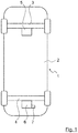
- Fig. 1 shows in a very schematic manner a motor vehicle 1, which in a known manner has a body 2, a front axle 3 and a rear axle 4 has.
- both the front axle 3 and the rear axle 4 are steered axles.
- respective steering systems are indicated which are assigned to the front axle 3 and the rear axle 4 and with which the front axle 3 and the rear axle 4 are steered.
- the steering system of the front axle 3 is referred to as the front axle steering 5
- the steering system of the rear axle 4 is referred to as the rear axle steering 6.
- the front-axle steering 5 is basically independent of the rear-axle steering 6, although certain dependencies can be established which, however, are not mechanical, but electronic.
- the rear axle steering 6 has a steering angle adjusting device 7 which basically serves to set a desired steering angle of the wheels of the rear axle 4.
- the steering angle adjusting device 7 initially receives a driver's request entered via a steering handle (not shown) and processes it to the respective steering angle of the rear axle 4 or the wheels of the rear axle 4.
- the steering angle adjusting device 7 is also able, for certain reasons described below, to deviate from the driver's request entered by the steering handle.
- the steering angle and possibly also the gradient of the steering angle of the wheels of the rear axle 4 can be limited as a function of a coefficient of friction of a road surface (not shown) on which the motor vehicle 1 is moving when the motor vehicle 1 reaches a predetermined transverse acceleration.
- the steering angle of the wheels of the rear axle 4 is set.
- the steering angle is set as a function of the coefficient of friction of the road surface and optionally also the gradient of the steering angle of the wheels of the rear axle 4 is limited.
- This method can be carried out by a device, not shown in its entirety, to which, among other things, the steering angle adjusting device 7 also belongs.
- the steering angle and possibly also the gradient of the steering angle are preferably limited when the road surface falls below a certain coefficient of friction.
- either only the steering angle or both the steering angle and the gradient of the steering angle can be limited.
- the latter is preferable.
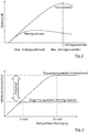
- Fig. 2 shows a characteristic field or a diagram in which the tire lateral force is plotted against the slip angle. It can be seen that on a road surface that has a low coefficient of friction, for example a snowy or icy road, the maximum lateral tire force is achieved at a significantly lower slip angle than on a road surface that has a high coefficient of friction. The maximum possible slip angle is therefore dependent on the coefficient of friction of the road surface.
- Fig. 3 shows a diagram in which the rear axle steering angle is plotted against the target transverse acceleration.
- the yaw gain describes the relationship between the wheel steering angle and the yaw rate of the motor vehicle 1.
- the maximum gradient of the rear axle steering movement d_ Delta HA depends on ⁇ utilization .
- the permitted gradient should drop to 0 ° / s in order to prevent further steering movement.
- a continuous drop in the gradient that is, a constant differentiability, is advantageous here. This is in Fig. 3 illustrated by the round course of the curve in the respective limit.
- the limitation of the steering angle of the wheels of rear axle 4 or the absolute rear axle steering angle can be determined as described below: In the ideal case, the maximum slip angle of the tires on the rear axle 4 is not exceeded when driving with the maximum possible transverse acceleration on the respective road surface.
- the limiting maximum rear axle steering angle thus corresponds to the rear axle steering angle at the nominal transverse acceleration, which reflects the adhesion potential of the road surface.
- the stationary rear axle steering angle basically results from the steering wheel angle sensor Delta LWI or the measured rack position of the front axle steering Delta EPS .
- the steering ratio HA is an application value for the characteristics of the rear axle steering 6.
- the coefficient of friction ⁇ of the road surface should be known at least approximately in order to carry out the method described.
- known procedures can be used, such as the estimation based on the deviation of the measured movement variables, such as B. yaw rate and / or lateral acceleration, from the model-based target values, estimation based on the wheel slippage, estimation from steering torques, information from a Car2X communication.
- sensors already present on the motor vehicle 1 can be used.
- All of the functions described here can be adjusted in their amplification, for example via the driving speed, the steering wheel angle, the steering wheel speed, in critical driving situations such as oversteering and understeering or depending on the selected driving profile.
Landscapes
- Engineering & Computer Science (AREA)
- Transportation (AREA)
- Mechanical Engineering (AREA)
- Chemical & Material Sciences (AREA)
- Combustion & Propulsion (AREA)
- Physics & Mathematics (AREA)
- Mathematical Physics (AREA)
- Theoretical Computer Science (AREA)
- Automation & Control Theory (AREA)
- Steering Control In Accordance With Driving Conditions (AREA)
Description
- Die Erfindung betrifft ein Verfahren zur Steuerung einer Hinterachslenkung eines Kraftfahrzeugs, wobei ein Lenkwinkel von Rädern der Hinterachse eingestellt wird, sowie eine Vorrichtung zur Durchführung des Verfahrens.
- Aus Sicherheitsgründen werden die aktuellen Serienfahrzeuge grundsätzlich untersteuernd ausgelegt. Bei einer Kurvenfahrt im querdynamischen Grenzbereich ist dabei der Schräglaufwinkel an der Hinterachse geringer als der Schräglaufwinkel an der Vorderachse, was ein unkontrolliertes Eindrehen des Fahrzeugs verhindert und es für den Fahrer beherrschbar macht.
- Kraftfahrzeuge mit einer Hinterrad- bzw. Hinterachslenkung können das dynamische Verhältnis der Schräglaufwinkel zwischen der Vorder- und der Hinterachse stark beeinflussen. Bei einer Lenkbewegung der Hinterachse proportional gegensinnig zur Vorderachse wird das Fahrverhalten in Richtung Übersteuern verändert. Bei einer gleichsinnigen Lenkbewegung verschiebt sich das Fahrverhalten dagegen in Richtung Untersteuern.
- Wenn im querdynamischen Grenzbereich gelenkt, insbesondere überlenkt, wird, erreicht die Vorderachse als erste den Schräglaufwinkel mit der maximalen Seitenkraft. Eine Erhöhung des Lenkwinkels, also ein Überlenken, führt danach zu einer Absenkung der Seitenkraft der Vorderachse. An der Hinterachse ist zu diesem Zeitpunkt der Schräglaufwinkel der maximalen Seiten kraft jedoch noch nicht erreicht, so dass eine gleichsinnige Lenkbewegung der Hinterachse zu einer Erhöhung der Seitenkraft an der Hinterachse führt. Die Hinterachslenkung fügt der vorhandenen Seitenkraft also eine zusätzliche Seitenkraft hinzu. Das Fahrverhalten wird dadurch stark untersteuernd und kann im Extremfall zur Geradeausfahrt und somit zum Verlassen der Fahrbahn führen.
- Analog dazu führt eine übermäßige gegensinnige Lenkbewegung der Hinterachslenkung im Grenzbereich zu einer Reduktion der Seitenkräfte an der Hinterachse. Das Fahrverhalten wird dadurch stark übersteuernd und kann im Extremfall zum extremen Eindrehen des Kraftfahrzeugs und zum Kontrollverlust führen.
- Die maximal möglichen Schräglaufwinkel sind abhängig vom Fahrbahnreibwert, also des Haftpotenzials der Fahrbahn. Auf rutschigem Untergrund, wie zum Beispiel auf einer verschneiten oder vereisten Straße, ist der maximale Schräglaufwinkel deutlich früher erreicht als auf trockenem Asphalt.
- Aus der
EP 0 510 365 A2 sind ein gattungsgemäßes Verfahren und eine entsprechende Vorrichtung zur Steuerung einer Hinterachslenkung eines Kraftfahrzeugs bekannt. Dabei wird mittels einer Feedback-Regelung, die auf der Gierrate des Kraftfahrzeugs basiert, eine Regelung des Lenkwinkels vorgenommen. - In der
DE 10 2010 036 619 A1 ist ein Verfahren zum Betreiben eines Lenksystems bei einem Kraftfahrzeug beschrieben, das eine Hinterachslenkung aufweist. Dabei wird ein Schräglaufwinkel der Vorderachse durch Lenken der Hinterachse derart beeinflusst, dass dieser über einen Lenkradwinkelbereich konstant bleibt. - Die
US 2008/0109133 A1 beschreibt ein Verfahren zur Begrenzung des Reifenschlupfwinkels in einem Lenksteuersystem für ein Kraftfahrzeug, bei dem ein erster Lenkvergrößerungswinkel aus einer Fahrzeuggeschwindigkeit und einem Lenkradwinkel berechnet wird. Des Weiteren werden eine obere Grenzwinkelgrenze und eine untere Grenzwinkelgrenze als Funktionen eines Fahrzeugschlupfwinkels und einer Reifenschlupfwinkelgrenze berechnet. Die Summe des Lenkradwinkels und des ersten Lenkvergrößerungswinkels zwischen der oberen Grenzwinkelgrenze und der unteren Grenzwinkelgrenze wird berechnet, um einen ersten begrenzten Winkel zu erzeugen. Des Weiteren wird die Summe aus dem Handradwinkel und dem ersten Lenkvergrößerungswinkel von dem ersten Begrenzungswinkel subtrahiert, um eine erste Begrenzungsfunktion zu erzeugen, und ein Motorwinkelbefehl wird durch Addieren der ersten Begrenzungsfunktion und dem ersten Lenkvergrößerungswinkel erzeugt. - Es ist Aufgabe der vorliegenden Erfindung, ein Verfahren zur Steuerung einer Hinterachslenkung eines Kraftfahrzeugs zu schaffen, mit der die Fahrsicherheit erhöht werden kann.
- Gemäß der vorliegenden Erfindung wird also bei Erreichen einer bestimmten Querbeschleunigung des Kraftfahrzeugs in Abhängigkeit des Reibwerts der Fahrbahnoberfläche der Lenkwinkel der Räder der Hinterachse begrenzt wird. Mit anderen Worten, es wird die vorgesteuerte Lenkbewegung der Hinterachse im querdynamischen Grenzbereich in Abhängigkeit des Fahrbahnreibwerts und der Reibwertausnutzung auf maximal zulässige Winkel begrenzt. Eine solche reibwertadaptive Begrenzung der vorgesteuerten Hinterachslenkwinkel bzw. -winkelgradienten und damit eine Begrenzung der Lenkbewegung der Hinterachse im Bereich des maximalen Schräglaufwinkels derselben verhindert unerwünschte Lenkbewegungen und damit die Entstehung von Unter- bzw. Übersteuern und führt somit zu einer wesentlich erhöhten Fahrsicherheit.
- Wenn in einer sehr vorteilhaften Weiterbildung der Erfindung der Lenkwinkel bei Unterschreiten eines bestimmten Reibwerts der Fahrbahnoberfläche begrenzt wird, so wird dem Umstand Rechnung getragen, dass die beschriebene Problematik gerade beim Fahren auf Fahrbahnoberflächen mit einem niedrigen Reibwert auftritt.
- Des Weiteren kann vorgesehen sein, dass der Lenkwinkel der Räder der Hinterachse mittels einer Lenkwinkelstelleinrichtung eingestellt wird, was eine sehr einfache Durchführung des Verfahrens sicherstellt.
- Besonders vorteilhaft ist es, wenn zusätzlich auch der Gradient des Lenkwinkels begrenzt wird.
- Wenn die Begrenzung des Lenkwinkels der Räder der Hinterachse in Abhängigkeit einer Fahrgeschwindigkeit des Kraftfahrzeugs durchgeführt wird, ergibt sich eine Erhöhung der Fahrsicherheit des Kraftfahrzeugs.
- Eine Vorrichtung zur Durchführung des Verfahrens ist in Anspruch 6 angegeben.
- Mit einer solchen Vorrichtung kann das erfindungsgemäße Verfahren auf sehr einfache Weise durchgeführt werden.
- Weitere Vorteile, Merkmale und Einzelheiten der Erfindung ergeben sich aus den Ansprüchen, der nachfolgenden Beschreibung bevorzugter Ausführungsformen sowie anhand der Zeichnungen. Dabei zeigen:
- Fig. 1
- eine schematische Draufsicht auf ein Kraftfahrzeug mit einer Vorrichtung zur Steuerung einer Hinterachslenkung;
- Fig. 2
- ein Diagramm, in dem die Reifenseitenkraft über dem Schräglaufwinkel aufgetragen ist; und
- Fig. 3
- ein Diagramm, in dem der Hinterachslenkwinkel über der Sollquerbeschleunigung aufgetragen ist.
-
Fig. 1 zeigt auf sehr schematische Weise ein Kraftfahrzeug 1, das in an sich bekannter Weise eine Karosserie 2, eine Vorderachse 3 und eine Hinterachse 4 aufweist. Im vorliegenden Fall handelt es sich sowohl bei der Vorderachse 3 als auch bei der Hinterachse 4 um gelenkte Achsen. Die Art und Weise, wie die Vorderachse 3 und die Hinterachse 4 gelenkt werden, wird hierin nicht ausführlich beschrieben. Es sind jedoch, ebenfalls sehr schematisch, jeweilige Lenksysteme angedeutet, die der Vorderachse 3 bzw. der Hinterachse 4 zugeordnet sind, und mit denen die Vorderachse 3 und die Hinterachse 4 gelenkt werden. Das Lenksystem der Vorderachse 3 wird dabei als Vorderachslenkung 5 und das Lenksystem der Hinterachse 4 als Hinterachslenkung 6 bezeichnet. Die Vorderachslenkung 5 ist dabei grundsätzlich unabhängig von der Hinterachslenkung 6, es können allerdings bestimmte Abhängigkeiten hergestellt werden, die jedoch nicht mechanischer, sondern elektronischer Art sind. - Die Hinterachslenkung 6 weist eine Lenkwinkelstelleinrichtung 7 auf, die grundsätzlich dazu dient, einen gewünschten Lenkwinkel der Räder der Hinterachse 4 einzustellen. Die Lenkwinkelstelleinrichtung 7 nimmt hierzu zunächst einen über eine nicht dargestellte Lenkhandhabe eingegebenen Fahrerwunsch auf und verarbeitet denselben zu dem jeweiligen Lenkwinkel der Hinterachse 4 bzw. der Räder der Hinterachse 4.
- Des Weiteren ist die Lenkwinkelstelleinrichtung 7 jedoch auch in der Lage, aus bestimmten, nachfolgend beschriebenen Gründen von dem per Lenkhandhabe eingegebenen Fahrerwunsch abzuweichen. So ist mit der Lenkwinkelstelleinrichtung 7 bei Erreichen einer vorbestimmten Querbeschleunigung des Kraftfahrzeugs 1 in Abhängigkeit eines Reibwerts einer nicht dargestellten Fahrbahnoberfläche, auf dem sich das Kraftfahrzeug 1 bewegt, der Lenkwinkel und gegebenenfalls auch der Gradient des Lenkwinkels der Räder der Hinterachse 4 begrenzbar.
- Bei einem Verfahren zur Steuerung der Hinterachslenkung 6 des Kraftfahrzeugs 1 wird der Lenkwinkel von Rädern der Hinterachse 4 eingestellt. Bei Erreichen einer vorbestimmten Querbeschleunigung des Kraftfahrzeugs 1 wird in Abhängigkeit des Reibwerts der Fahrbahnoberfläche der Lenkwinkel und gegebenenfalls auch der Gradient des Lenkwinkels der Räder der Hinterachse 4 begrenzt. Dieses Verfahren kann von einer in ihrer Gesamtheit nicht dargestellten Vorrichtung durchgeführt werden, zu der unter anderem auch die Lenkwinkelstelleinrichtung 7 gehört. Vorzugsweise wird der Lenkwinkel und gegebenenfalls auch der Gradient des Lenkwinkels bei Unterschreiten eines bestimmten Reibwerts der Fahrbahnoberfläche begrenzt.
- Demnach kann entweder nur der Lenkwinkel oder sowohl der Lenkwinkel als auch der Gradient des Lenkwinkels begrenzt werden. Letzteres ist dabei zu bevorzugen.
-
Fig. 2 zeigt ein Kennfeld bzw. ein Diagramm, in dem die Reifenseitenkraft über dem Schräglaufwinkel aufgetragen ist. Dabei ist zu erkennen, dass auf einer Fahrbahnoberfläche, die einen niedrigen Reibwert aufweist, also zum Beispiel eine verschneite oder vereiste Straße, die maximale Reifenseitenkraft bei einem erheblich niedrigeren Schräglaufwinkel erreicht wird als auf einer Fahrbahnoberfläche, die einen hohen Reibwert aufweist. Der maximal mögliche Schräglaufwinkel ist also vom Reibwert der Fahrbahnoberfläche abhängig. - Das oben beschriebene Verfahren, bei dem der Lenkwinkel und gegebenenfalls auch der Gradient des Lenkwinkels der Räder der Hinterachse 4 begrenzt wird, wird aus den nachfolgend erläuterten Gründen durchgeführt: Beim Lenken im querdynamischen Grenzbereich erreicht die Vorderachse 3 des Kraftfahrzeugs 1 zuerst den Schräglaufwinkel mit der maximalen Seitenkraft. Eine Erhöhung des Lenkwinkels, also ein Überlenken, führt danach zu einer Absenkung der Seitenkraft der Vorderachse 3. An der Hinterachse 4 ist zu diesem Zeitpunkt der Schräglaufwinkel der maximalen Seiten kraft jedoch noch nicht erreicht, so dass eine gleichsinnige Lenkbewegung der Hinterachse 4 zu einer Erhöhung der Seitenkraft an der Hinterachse 4 führt. Das Fahrverhalten wird dadurch stark untersteuernd und kann im Extremfall zur Geradeausfahrt und somit zum Verlassen der Fahrbahn führen. In ähnlicher Weise führt eine übermäßige gegensinnige Lenkbewegung der Hinterachslenkung 6 im Grenzbereich zu einer Reduktion der Seitenkräfte an der Hinterachse 4. Das Fahrverhalten wird dadurch stark übersteuernd und kann im Extremfall zum extremen Eindrehen des Kraftfahrzeugs 1 und zum Kontrollverlust führen.
-
Fig. 3 zeigt ein Diagramm, in dem der Hinterachslenkwinkel über der Sollquerbeschleunigung aufgetragen ist. - Die Begrenzung des Gradienten des Lenkwinkels der Räder der Hinterachse 4 bzw. des Gradienten des Hinterachslenkwinkels kann wie nachfolgend beschrieben ermittelt werden:
Zur genauen Ermittlung des Fahrzustandes mit maximal erlaubtem Schräglaufwinkel auf jedem Fahrbahnuntergrund wird die Reibwertausnutzung wie folgt definiert:
- Der Wertebereich ist auf [0 1] begrenzt, g ist die Gravitationskonstante und µ der geschätzte Fahrbahnreibwert. Die Sollquerbeschleunigung ergibt sich aus dem Lenkradwinkelsensor DeltaLWI oder der gemessenen Zahnstangenposition der Vorderachslenkung 5 DeltaEPS. Eine beispielhafte Berechnung dafür könnte wie folgt aussehen:


- Die Gierverstärkung beschreibt den Zusammenhang zwischen Radlenkwinkel und Gierrate des Kraftfahrzeugs 1.
- Der maximale Gradient der Hinterachslenkbewegung d_ DeltaHA hängt von µAusnutzung ab. Bei einer Reibwertausnutzung von 1 soll der erlaubte Gradient auf 0 °/s sinken, um eine weitere Lenkbewegung zu verhindern. Ein kontinuierlicher Abfall des Gradienten, also eine stetige Differenzierbarkeit, ist dabei vorteilhaft. Dies ist in
Fig. 3 durch den runden Verlauf der Kurve in die jeweilige Grenze verdeutlicht. - Die Begrenzung des Lenkwinkels der Räder der Hinterachse 4 bzw. des absoluten Hinterachslenkwinkels kann wie nachfolgend beschrieben ermittelt werden:
Im Idealfall wird das Schräglaufwinkelmaximum der Reifen an der Hinterachse 4 bei einer Fahrt mit der auf der jeweiligen Fahrbahnoberfläche maximal möglichen Querbeschleunigung nicht überschritten. Der begrenzende maximale Hinterachslenkwinkel entspricht somit dem Hinterachslenkwinkel bei der Sollquerbeschleunigung, die das Haftpotenzial der Fahrbahnoberfläche wiedergibt. - Der stationäre Hinterachslenkwinkel ergibt sich grundsätzlich aus dem Lenkradwinkelsensor DeltaLWI oder der gemessenen Zahnstangenposition der Vorderachslenkung DeltaEPS. Eine beispielhafte Berechnung dafür könnte wie folgt aussehen:


- Die LenkübersetzungHA ist ein Applikationswert für die Charakteristik der Hinterachslenkung 6.
- Die maximale Querbeschleunigung ergibt sich aus dem Reibwertpotenzial µ mit der Gravitationskonstanten g wie folgt:

- Aus den oben genannten Gleichungen lässt sich der maximale Hinterachslenkwinkel wie folgt berechnen:

- Es ist ersichtlich, dass zur Durchführung des beschriebenen Verfahrens der Reibwerts µ der Fahrbahnoberfläche zumindest näherungsweise bekannt sein sollte. Zur Bestimmung desselben kann auf bekannte Vorgehensweisen zurückgegriffen werden, wie zum Beispiel der Schätzung anhand der Abweichung der gemessenen Bewegungsgrößen, wie z. B. Gierrate und/oder Querbeschleunigung, von den modellbasierten Sollgrößen, Schätzung anhand der Radschlüpfe, Schätzung aus Lenkmomenten, Informationen aus einer Car2X-Kommunikation. Hierzu können an dem Kraftfahrzeug 1 bereits vorhandene Sensoren eingesetzt werden.
- Alle hierin beschriebenen Funktionen können in ihrer Verstärkung beispielsweise über der Fahrgeschwindigkeit, dem Lenkradwinkel, der Lenkradgeschwindigkeit, in kritischen Fahrsituationen wie Über- und Untersteuern oder in Abhängigkeit vom gewählten Fahrprofil angepasst werden.
Claims (6)
- Verfahren zur Steuerung einer Hinterachslenkung (6) eines Kraftfahrzeugs (1), wobei ein Lenkwinkel von Rädern einer Hinterachse (4) eingestellt wird,
dadurch gekennzeichnet, dass
bei Erreichen einer vorbestimmten Querbeschleunigung des Kraftfahrzeugs (1) in Abhängigkeit eines Reibwerts einer Fahrbahnoberfläche, auf dem sich das Kraftfahrzeug (1) bewegt, der Lenkwinkel der Räder der Hinterachse (4) begrenzt wird. - Verfahren nach Anspruch 1,
dadurch gekennzeichnet, dass
der Lenkwinkel bei Unterschreiten eines bestimmten Reibwerts der Fahrbahnoberfläche begrenzt wird. - Verfahren nach Anspruch 1 oder 2,
dadurch gekennzeichnet, dass
der Lenkwinkel der Räder der Hinterachse (4) mittels einer Lenkwinkelstelleinrichtung (7) eingestellt wird. - Verfahren nach Anspruch 1, 2 oder 3,
dadurch gekennzeichnet, dass
zusätzlich auch der Gradient des Lenkwinkels begrenzt wird. - Verfahren nach einem der Ansprüche 1 bis 4,
dadurch gekennzeichnet, dass
die Begrenzung des Lenkwinkels der Räder der Hinterachse (4) in Abhängigkeit einer Fahrgeschwindigkeit des Kraftfahrzeugs (1) durchgeführt wird. - Vorrichtung zur Durchführung des Verfahrens nach einem der Ansprüche 1 bis 5, mit einer Lenkwinkelstelleinrichtung (7), mit welcher bei Erreichen einer vorbestimmten Querbeschleunigung des Kraftfahrzeugs (1) in Abhängigkeit eines Reibwerts einer Fahrbahnoberfläche, auf dem sich das Kraftfahrzeug (1) bewegt, der Lenkwinkel der Räder der Hinterachse (4) begrenzbar ist.
Applications Claiming Priority (1)
| Application Number | Priority Date | Filing Date | Title |
|---|---|---|---|
| DE102017219881.8A DE102017219881A1 (de) | 2017-11-08 | 2017-11-08 | Verfahren zur Steuerung einer Hinterachslenkung eines Kraftfahrzeugs |
Publications (2)
| Publication Number | Publication Date |
|---|---|
| EP3483038A1 EP3483038A1 (de) | 2019-05-15 |
| EP3483038B1 true EP3483038B1 (de) | 2020-12-09 |
Family
ID=63878557
Family Applications (1)
| Application Number | Title | Priority Date | Filing Date |
|---|---|---|---|
| EP18201015.7A Active EP3483038B1 (de) | 2017-11-08 | 2018-10-17 | Verfahren zur steuerung einer hinterachslenkung eines kraftfahrzeugs |
Country Status (5)
| Country | Link |
|---|---|
| US (1) | US11059515B2 (de) |
| EP (1) | EP3483038B1 (de) |
| KR (1) | KR20190052639A (de) |
| CN (1) | CN109747710B (de) |
| DE (1) | DE102017219881A1 (de) |
Families Citing this family (3)
| Publication number | Priority date | Publication date | Assignee | Title |
|---|---|---|---|---|
| DE102019133917B4 (de) | 2019-12-11 | 2022-11-03 | Bayerische Motoren Werke Aktiengesellschaft | Verfahren und Vorrichtung zur Steuerung einer Hinterachslenkung |
| DE102020209961A1 (de) * | 2020-08-06 | 2022-02-10 | Zf Friedrichshafen Ag | Verfahren zum Betreiben einer Steer-by-Wire-Lenkung eines Kraftfahrzeugs sowie Steuergerät, Computerprogramm und Steer-by-Wire-Lenkung |
| DE102021200370B4 (de) * | 2021-01-15 | 2024-03-21 | Zf Friedrichshafen Ag | Verfahren zum Betreiben sowie Steuereinheit zum Steuern eines Aktuators einer steer-by-wire-Lenkung eines Kraftfahrzeugs sowie steer-by-wire-Lenkung |
Citations (1)
| Publication number | Priority date | Publication date | Assignee | Title |
|---|---|---|---|---|
| DE102004036565A1 (de) * | 2004-07-28 | 2006-02-16 | Robert Bosch Gmbh | Koordination eines Fahrdynamikregelungssystems mit einem Hinterachslenksystem |
Family Cites Families (9)
| Publication number | Priority date | Publication date | Assignee | Title |
|---|---|---|---|---|
| DE3807100A1 (de) * | 1988-03-04 | 1989-09-14 | Bayerische Motoren Werke Ag | Verfahren zum steuern der hinterraeder von kraftfahrzeugen |
| JPH04126668A (ja) * | 1990-09-17 | 1992-04-27 | Nissan Motor Co Ltd | 舵角制御装置 |
| US5386365A (en) * | 1991-03-22 | 1995-01-31 | Mazda Motor Corporation | Rear wheel steering system for vehicle |
| DE102007020169A1 (de) * | 2006-04-27 | 2007-10-31 | Continental Teves Ag & Co. Ohg | Verfahren und Vorrichtung zum Ermitteln eines optimalen Lenkwinkels in Untersteuersituationen eines Fahrzeugs |
| US7756620B2 (en) | 2006-11-06 | 2010-07-13 | Gm Global Technology Operations, Inc. | Methods, systems, and computer program products for tire slip angle limiting in a steering control system |
| JP4924378B2 (ja) * | 2007-11-19 | 2012-04-25 | トヨタ自動車株式会社 | 車輌の走行制御装置 |
| DE102010036619B4 (de) * | 2010-07-26 | 2020-08-27 | Dr. Ing. H.C. F. Porsche Aktiengesellschaft | Verfahren zum Betreiben eines Lenksystems |
| DE102011016633A1 (de) * | 2011-04-09 | 2012-10-11 | Audi Ag | Verfahren zum Betreiben eines mit einer Hinterachslenkung ausgestatteten Kraftfahrzeugs |
| CN104443022B (zh) * | 2014-11-11 | 2018-12-11 | 深圳职业技术学院 | 一种四轮独立驱动电动汽车稳定性控制方法及系统 |
-
2017
- 2017-11-08 DE DE102017219881.8A patent/DE102017219881A1/de not_active Withdrawn
-
2018
- 2018-10-17 EP EP18201015.7A patent/EP3483038B1/de active Active
- 2018-11-05 CN CN201811305752.3A patent/CN109747710B/zh active Active
- 2018-11-07 KR KR1020180135802A patent/KR20190052639A/ko not_active Ceased
- 2018-11-07 US US16/183,046 patent/US11059515B2/en active Active
Patent Citations (1)
| Publication number | Priority date | Publication date | Assignee | Title |
|---|---|---|---|---|
| DE102004036565A1 (de) * | 2004-07-28 | 2006-02-16 | Robert Bosch Gmbh | Koordination eines Fahrdynamikregelungssystems mit einem Hinterachslenksystem |
Also Published As
| Publication number | Publication date |
|---|---|
| DE102017219881A1 (de) | 2019-05-09 |
| US20190135337A1 (en) | 2019-05-09 |
| EP3483038A1 (de) | 2019-05-15 |
| KR20190052639A (ko) | 2019-05-16 |
| CN109747710A (zh) | 2019-05-14 |
| CN109747710B (zh) | 2021-06-22 |
| US11059515B2 (en) | 2021-07-13 |
Similar Documents
| Publication | Publication Date | Title |
|---|---|---|
| EP2013069B1 (de) | Verfahren und vorrichtung zum ermitteln eines optimalen lenkwinkels in untersteuersituationen eines fahrzeugs | |
| EP1000838B9 (de) | Verfahren zur Regelung der Querdynamik eines Fahrzeuges mit Vorderachs-Lenkung | |
| EP1807300B1 (de) | Verfahren und vorrichtung zum unterstützen eines fahrzeugbedieners beim stabilisieren eines fahrzeugs | |
| DE3804587C2 (de) | ||
| DE102016215793B4 (de) | Fahrzeug sowie Verfahren zum Lenken des Fahrzeugs | |
| EP2512886B1 (de) | Verfahren und bremssystem zur beeinflussung der fahrdynamik durch brems- und antriebseingriff | |
| EP1399344B1 (de) | Verfahren zur regelung der fahrstabilität | |
| DE10348738B4 (de) | Steuerungssystem für ein Kraftfahrzeug und Verfahren zum Steuern eines Kraftfahrzeugs | |
| EP3328693B1 (de) | Verfahren zur fahrerunterstützung bei wasserglätte auf einem fahrbahnuntergrund | |
| EP1694542B1 (de) | Fahrdynamikregelung mit vorgezogenem druckaufbau am zu regelnden rad | |
| DE102016217465B4 (de) | Verfahren zur Regelung eines Kraftfahrzeugs und elektronisches Bremsensteuergerät | |
| DE102007051590A1 (de) | Verfahren zum Verteilen von Antriebs- oder Schleppmomenten auf die angetriebenen Räder eines Kfz | |
| EP0897359A1 (de) | Verfahren zur bestimmung eines fahrzeug-sollverhaltens | |
| EP3740392B1 (de) | Verfahren zum vermeiden von überschlägen eines kraftfahrzeuges mittels torque vectoring, korrespondierendes lenksystem | |
| EP3483038B1 (de) | Verfahren zur steuerung einer hinterachslenkung eines kraftfahrzeugs | |
| DE10348736B4 (de) | Steuerungssystem für ein Fahrzeug und Verfahren zum Steuern eines Fahrzeugs | |
| DE102005018519B4 (de) | Verfahren zur Fahrdynamik-Regelung von Kraftfahrzeugen | |
| DE102005053864B4 (de) | Verfahren, Steuergerät und Vorrichtung zum Stabilisieren eines Fahrzeugs in fahrdynamischen Grenzsituationen | |
| WO2010089061A1 (de) | Verfahren zur steuerung eines spurhalteassistenten und spurhalteassistent | |
| EP3487732B1 (de) | Reibwertschätzer | |
| DE102005012584B4 (de) | Verfahren und Vorrichtung zum Erhöhen der Fahrstabilität eines Fahrzeugs während der Fahrt durch eine Kurve | |
| DE102005019337A1 (de) | Fahrzeugsteuersystem zur Erleichterung des Herausfahrens aus Fahrrinnen und damit ausgestattetes Kraftfahrzeug | |
| EP1799484B1 (de) | Verfahren und vorrichtung zum steuern des sperrgrades einer elektronisch steuerbaren differenzialsperre | |
| DE102010036619B4 (de) | Verfahren zum Betreiben eines Lenksystems | |
| EP1802481B1 (de) | Verfahren und vorrichtung zum steuern des sperrgrades einer elektronisch steuerbaren differenzialsperre |
Legal Events
| Date | Code | Title | Description |
|---|---|---|---|
| PUAI | Public reference made under article 153(3) epc to a published international application that has entered the european phase |
Free format text: ORIGINAL CODE: 0009012 |
|
| STAA | Information on the status of an ep patent application or granted ep patent |
Free format text: STATUS: THE APPLICATION HAS BEEN PUBLISHED |
|
| AK | Designated contracting states |
Kind code of ref document: A1 Designated state(s): AL AT BE BG CH CY CZ DE DK EE ES FI FR GB GR HR HU IE IS IT LI LT LU LV MC MK MT NL NO PL PT RO RS SE SI SK SM TR |
|
| AX | Request for extension of the european patent |
Extension state: BA ME |
|
| STAA | Information on the status of an ep patent application or granted ep patent |
Free format text: STATUS: REQUEST FOR EXAMINATION WAS MADE |
|
| 17P | Request for examination filed |
Effective date: 20191115 |
|
| RBV | Designated contracting states (corrected) |
Designated state(s): AL AT BE BG CH CY CZ DE DK EE ES FI FR GB GR HR HU IE IS IT LI LT LU LV MC MK MT NL NO PL PT RO RS SE SI SK SM TR |
|
| GRAP | Despatch of communication of intention to grant a patent |
Free format text: ORIGINAL CODE: EPIDOSNIGR1 |
|
| STAA | Information on the status of an ep patent application or granted ep patent |
Free format text: STATUS: GRANT OF PATENT IS INTENDED |
|
| RIC1 | Information provided on ipc code assigned before grant |
Ipc: B62D 7/15 20060101ALI20200619BHEP Ipc: B62D 6/00 20060101AFI20200619BHEP Ipc: B60W 30/045 20120101ALI20200619BHEP |
|
| INTG | Intention to grant announced |
Effective date: 20200707 |
|
| GRAS | Grant fee paid |
Free format text: ORIGINAL CODE: EPIDOSNIGR3 |
|
| GRAA | (expected) grant |
Free format text: ORIGINAL CODE: 0009210 |
|
| STAA | Information on the status of an ep patent application or granted ep patent |
Free format text: STATUS: THE PATENT HAS BEEN GRANTED |
|
| AK | Designated contracting states |
Kind code of ref document: B1 Designated state(s): AL AT BE BG CH CY CZ DE DK EE ES FI FR GB GR HR HU IE IS IT LI LT LU LV MC MK MT NL NO PL PT RO RS SE SI SK SM TR |
|
| REG | Reference to a national code |
Ref country code: GB Ref legal event code: FG4D Free format text: NOT ENGLISH |
|
| REG | Reference to a national code |
Ref country code: AT Ref legal event code: REF Ref document number: 1343150 Country of ref document: AT Kind code of ref document: T Effective date: 20201215 Ref country code: CH Ref legal event code: EP |
|
| REG | Reference to a national code |
Ref country code: DE Ref legal event code: R096 Ref document number: 502018003254 Country of ref document: DE |
|
| REG | Reference to a national code |
Ref country code: IE Ref legal event code: FG4D Free format text: LANGUAGE OF EP DOCUMENT: GERMAN |
|
| PG25 | Lapsed in a contracting state [announced via postgrant information from national office to epo] |
Ref country code: RS Free format text: LAPSE BECAUSE OF FAILURE TO SUBMIT A TRANSLATION OF THE DESCRIPTION OR TO PAY THE FEE WITHIN THE PRESCRIBED TIME-LIMIT Effective date: 20201209 Ref country code: FI Free format text: LAPSE BECAUSE OF FAILURE TO SUBMIT A TRANSLATION OF THE DESCRIPTION OR TO PAY THE FEE WITHIN THE PRESCRIBED TIME-LIMIT Effective date: 20201209 Ref country code: GR Free format text: LAPSE BECAUSE OF FAILURE TO SUBMIT A TRANSLATION OF THE DESCRIPTION OR TO PAY THE FEE WITHIN THE PRESCRIBED TIME-LIMIT Effective date: 20210310 Ref country code: NO Free format text: LAPSE BECAUSE OF FAILURE TO SUBMIT A TRANSLATION OF THE DESCRIPTION OR TO PAY THE FEE WITHIN THE PRESCRIBED TIME-LIMIT Effective date: 20210309 |
|
| PG25 | Lapsed in a contracting state [announced via postgrant information from national office to epo] |
Ref country code: BG Free format text: LAPSE BECAUSE OF FAILURE TO SUBMIT A TRANSLATION OF THE DESCRIPTION OR TO PAY THE FEE WITHIN THE PRESCRIBED TIME-LIMIT Effective date: 20210309 Ref country code: SE Free format text: LAPSE BECAUSE OF FAILURE TO SUBMIT A TRANSLATION OF THE DESCRIPTION OR TO PAY THE FEE WITHIN THE PRESCRIBED TIME-LIMIT Effective date: 20201209 Ref country code: LV Free format text: LAPSE BECAUSE OF FAILURE TO SUBMIT A TRANSLATION OF THE DESCRIPTION OR TO PAY THE FEE WITHIN THE PRESCRIBED TIME-LIMIT Effective date: 20201209 |
|
| REG | Reference to a national code |
Ref country code: NL Ref legal event code: MP Effective date: 20201209 |
|
| PG25 | Lapsed in a contracting state [announced via postgrant information from national office to epo] |
Ref country code: NL Free format text: LAPSE BECAUSE OF FAILURE TO SUBMIT A TRANSLATION OF THE DESCRIPTION OR TO PAY THE FEE WITHIN THE PRESCRIBED TIME-LIMIT Effective date: 20201209 Ref country code: HR Free format text: LAPSE BECAUSE OF FAILURE TO SUBMIT A TRANSLATION OF THE DESCRIPTION OR TO PAY THE FEE WITHIN THE PRESCRIBED TIME-LIMIT Effective date: 20201209 |
|
| REG | Reference to a national code |
Ref country code: LT Ref legal event code: MG9D |
|
| PG25 | Lapsed in a contracting state [announced via postgrant information from national office to epo] |
Ref country code: SM Free format text: LAPSE BECAUSE OF FAILURE TO SUBMIT A TRANSLATION OF THE DESCRIPTION OR TO PAY THE FEE WITHIN THE PRESCRIBED TIME-LIMIT Effective date: 20201209 Ref country code: SK Free format text: LAPSE BECAUSE OF FAILURE TO SUBMIT A TRANSLATION OF THE DESCRIPTION OR TO PAY THE FEE WITHIN THE PRESCRIBED TIME-LIMIT Effective date: 20201209 Ref country code: EE Free format text: LAPSE BECAUSE OF FAILURE TO SUBMIT A TRANSLATION OF THE DESCRIPTION OR TO PAY THE FEE WITHIN THE PRESCRIBED TIME-LIMIT Effective date: 20201209 Ref country code: CZ Free format text: LAPSE BECAUSE OF FAILURE TO SUBMIT A TRANSLATION OF THE DESCRIPTION OR TO PAY THE FEE WITHIN THE PRESCRIBED TIME-LIMIT Effective date: 20201209 Ref country code: PT Free format text: LAPSE BECAUSE OF FAILURE TO SUBMIT A TRANSLATION OF THE DESCRIPTION OR TO PAY THE FEE WITHIN THE PRESCRIBED TIME-LIMIT Effective date: 20210409 Ref country code: RO Free format text: LAPSE BECAUSE OF FAILURE TO SUBMIT A TRANSLATION OF THE DESCRIPTION OR TO PAY THE FEE WITHIN THE PRESCRIBED TIME-LIMIT Effective date: 20201209 Ref country code: LT Free format text: LAPSE BECAUSE OF FAILURE TO SUBMIT A TRANSLATION OF THE DESCRIPTION OR TO PAY THE FEE WITHIN THE PRESCRIBED TIME-LIMIT Effective date: 20201209 |
|
| PG25 | Lapsed in a contracting state [announced via postgrant information from national office to epo] |
Ref country code: PL Free format text: LAPSE BECAUSE OF FAILURE TO SUBMIT A TRANSLATION OF THE DESCRIPTION OR TO PAY THE FEE WITHIN THE PRESCRIBED TIME-LIMIT Effective date: 20201209 |
|
| REG | Reference to a national code |
Ref country code: DE Ref legal event code: R097 Ref document number: 502018003254 Country of ref document: DE |
|
| PG25 | Lapsed in a contracting state [announced via postgrant information from national office to epo] |
Ref country code: IS Free format text: LAPSE BECAUSE OF FAILURE TO SUBMIT A TRANSLATION OF THE DESCRIPTION OR TO PAY THE FEE WITHIN THE PRESCRIBED TIME-LIMIT Effective date: 20210409 |
|
| PLBE | No opposition filed within time limit |
Free format text: ORIGINAL CODE: 0009261 |
|
| STAA | Information on the status of an ep patent application or granted ep patent |
Free format text: STATUS: NO OPPOSITION FILED WITHIN TIME LIMIT |
|
| PG25 | Lapsed in a contracting state [announced via postgrant information from national office to epo] |
Ref country code: AL Free format text: LAPSE BECAUSE OF FAILURE TO SUBMIT A TRANSLATION OF THE DESCRIPTION OR TO PAY THE FEE WITHIN THE PRESCRIBED TIME-LIMIT Effective date: 20201209 Ref country code: IT Free format text: LAPSE BECAUSE OF FAILURE TO SUBMIT A TRANSLATION OF THE DESCRIPTION OR TO PAY THE FEE WITHIN THE PRESCRIBED TIME-LIMIT Effective date: 20201209 |
|
| 26N | No opposition filed |
Effective date: 20210910 |
|
| PG25 | Lapsed in a contracting state [announced via postgrant information from national office to epo] |
Ref country code: DK Free format text: LAPSE BECAUSE OF FAILURE TO SUBMIT A TRANSLATION OF THE DESCRIPTION OR TO PAY THE FEE WITHIN THE PRESCRIBED TIME-LIMIT Effective date: 20201209 Ref country code: SI Free format text: LAPSE BECAUSE OF FAILURE TO SUBMIT A TRANSLATION OF THE DESCRIPTION OR TO PAY THE FEE WITHIN THE PRESCRIBED TIME-LIMIT Effective date: 20201209 |
|
| PG25 | Lapsed in a contracting state [announced via postgrant information from national office to epo] |
Ref country code: ES Free format text: LAPSE BECAUSE OF FAILURE TO SUBMIT A TRANSLATION OF THE DESCRIPTION OR TO PAY THE FEE WITHIN THE PRESCRIBED TIME-LIMIT Effective date: 20201209 |
|
| REG | Reference to a national code |
Ref country code: CH Ref legal event code: PL |
|
| PG25 | Lapsed in a contracting state [announced via postgrant information from national office to epo] |
Ref country code: IS Free format text: LAPSE BECAUSE OF FAILURE TO SUBMIT A TRANSLATION OF THE DESCRIPTION OR TO PAY THE FEE WITHIN THE PRESCRIBED TIME-LIMIT Effective date: 20210409 |
|
| REG | Reference to a national code |
Ref country code: BE Ref legal event code: MM Effective date: 20211031 |
|
| PG25 | Lapsed in a contracting state [announced via postgrant information from national office to epo] |
Ref country code: MC Free format text: LAPSE BECAUSE OF FAILURE TO SUBMIT A TRANSLATION OF THE DESCRIPTION OR TO PAY THE FEE WITHIN THE PRESCRIBED TIME-LIMIT Effective date: 20201209 |
|
| PG25 | Lapsed in a contracting state [announced via postgrant information from national office to epo] |
Ref country code: LU Free format text: LAPSE BECAUSE OF NON-PAYMENT OF DUE FEES Effective date: 20211017 Ref country code: BE Free format text: LAPSE BECAUSE OF NON-PAYMENT OF DUE FEES Effective date: 20211031 |
|
| PG25 | Lapsed in a contracting state [announced via postgrant information from national office to epo] |
Ref country code: LI Free format text: LAPSE BECAUSE OF NON-PAYMENT OF DUE FEES Effective date: 20211031 Ref country code: CH Free format text: LAPSE BECAUSE OF NON-PAYMENT OF DUE FEES Effective date: 20211031 |
|
| PG25 | Lapsed in a contracting state [announced via postgrant information from national office to epo] |
Ref country code: IE Free format text: LAPSE BECAUSE OF NON-PAYMENT OF DUE FEES Effective date: 20211017 |
|
| PG25 | Lapsed in a contracting state [announced via postgrant information from national office to epo] |
Ref country code: CY Free format text: LAPSE BECAUSE OF FAILURE TO SUBMIT A TRANSLATION OF THE DESCRIPTION OR TO PAY THE FEE WITHIN THE PRESCRIBED TIME-LIMIT Effective date: 20201209 |
|
| P01 | Opt-out of the competence of the unified patent court (upc) registered |
Effective date: 20230530 |
|
| PG25 | Lapsed in a contracting state [announced via postgrant information from national office to epo] |
Ref country code: HU Free format text: LAPSE BECAUSE OF FAILURE TO SUBMIT A TRANSLATION OF THE DESCRIPTION OR TO PAY THE FEE WITHIN THE PRESCRIBED TIME-LIMIT; INVALID AB INITIO Effective date: 20181017 |
|
| PG25 | Lapsed in a contracting state [announced via postgrant information from national office to epo] |
Ref country code: MK Free format text: LAPSE BECAUSE OF FAILURE TO SUBMIT A TRANSLATION OF THE DESCRIPTION OR TO PAY THE FEE WITHIN THE PRESCRIBED TIME-LIMIT Effective date: 20201209 |
|
| PG25 | Lapsed in a contracting state [announced via postgrant information from national office to epo] |
Ref country code: MT Free format text: LAPSE BECAUSE OF FAILURE TO SUBMIT A TRANSLATION OF THE DESCRIPTION OR TO PAY THE FEE WITHIN THE PRESCRIBED TIME-LIMIT Effective date: 20201209 |
|
| REG | Reference to a national code |
Ref country code: AT Ref legal event code: MM01 Ref document number: 1343150 Country of ref document: AT Kind code of ref document: T Effective date: 20231017 |
|
| PG25 | Lapsed in a contracting state [announced via postgrant information from national office to epo] |
Ref country code: AT Free format text: LAPSE BECAUSE OF NON-PAYMENT OF DUE FEES Effective date: 20231017 |
|
| PG25 | Lapsed in a contracting state [announced via postgrant information from national office to epo] |
Ref country code: AT Free format text: LAPSE BECAUSE OF NON-PAYMENT OF DUE FEES Effective date: 20231017 |
|
| PG25 | Lapsed in a contracting state [announced via postgrant information from national office to epo] |
Ref country code: TR Free format text: LAPSE BECAUSE OF FAILURE TO SUBMIT A TRANSLATION OF THE DESCRIPTION OR TO PAY THE FEE WITHIN THE PRESCRIBED TIME-LIMIT Effective date: 20201209 |
|
| PGFP | Annual fee paid to national office [announced via postgrant information from national office to epo] |
Ref country code: DE Payment date: 20251031 Year of fee payment: 8 |
|
| PGFP | Annual fee paid to national office [announced via postgrant information from national office to epo] |
Ref country code: GB Payment date: 20251024 Year of fee payment: 8 |
|
| PGFP | Annual fee paid to national office [announced via postgrant information from national office to epo] |
Ref country code: FR Payment date: 20251024 Year of fee payment: 8 |
|
| PGFP | Annual fee paid to national office [announced via postgrant information from national office to epo] |
Ref country code: AT Payment date: 20260410 Year of fee payment: 5 |