EP3483081B1 - Kunstharzbehälter - Google Patents
Kunstharzbehälter Download PDFInfo
- Publication number
- EP3483081B1 EP3483081B1 EP17824099.0A EP17824099A EP3483081B1 EP 3483081 B1 EP3483081 B1 EP 3483081B1 EP 17824099 A EP17824099 A EP 17824099A EP 3483081 B1 EP3483081 B1 EP 3483081B1
- Authority
- EP
- European Patent Office
- Prior art keywords
- concave groove
- body portion
- container
- cross
- section shape
- Prior art date
- Legal status (The legal status is an assumption and is not a legal conclusion. Google has not performed a legal analysis and makes no representation as to the accuracy of the status listed.)
- Not-in-force
Links
Images



Classifications
-
- B—PERFORMING OPERATIONS; TRANSPORTING
- B65—CONVEYING; PACKING; STORING; HANDLING THIN OR FILAMENTARY MATERIAL
- B65D—CONTAINERS FOR STORAGE OR TRANSPORT OF ARTICLES OR MATERIALS, e.g. BAGS, BARRELS, BOTTLES, BOXES, CANS, CARTONS, CRATES, DRUMS, JARS, TANKS, HOPPERS, FORWARDING CONTAINERS; ACCESSORIES, CLOSURES, OR FITTINGS THEREFOR; PACKAGING ELEMENTS; PACKAGES
- B65D1/00—Rigid or semi-rigid containers having bodies formed in one piece, e.g. by casting metallic material, by moulding plastics, by blowing vitreous material, by throwing ceramic material, by moulding pulped fibrous material or by deep-drawing operations performed on sheet material
- B65D1/02—Bottles or similar containers with necks or like restricted apertures, designed for pouring contents
- B65D1/0223—Bottles or similar containers with necks or like restricted apertures, designed for pouring contents characterised by shape
-
- B—PERFORMING OPERATIONS; TRANSPORTING
- B65—CONVEYING; PACKING; STORING; HANDLING THIN OR FILAMENTARY MATERIAL
- B65D—CONTAINERS FOR STORAGE OR TRANSPORT OF ARTICLES OR MATERIALS, e.g. BAGS, BARRELS, BOTTLES, BOXES, CANS, CARTONS, CRATES, DRUMS, JARS, TANKS, HOPPERS, FORWARDING CONTAINERS; ACCESSORIES, CLOSURES, OR FITTINGS THEREFOR; PACKAGING ELEMENTS; PACKAGES
- B65D79/00—Kinds or details of packages, not otherwise provided for
- B65D79/005—Packages having deformable parts for indicating or neutralizing internal pressure-variations by other means than venting
- B65D79/008—Packages having deformable parts for indicating or neutralizing internal pressure-variations by other means than venting the deformable part being located in a rigid or semi-rigid container, e.g. in bottles or jars
- B65D79/0084—Packages having deformable parts for indicating or neutralizing internal pressure-variations by other means than venting the deformable part being located in a rigid or semi-rigid container, e.g. in bottles or jars in the sidewall or shoulder part thereof
-
- B—PERFORMING OPERATIONS; TRANSPORTING
- B29—WORKING OF PLASTICS; WORKING OF SUBSTANCES IN A PLASTIC STATE IN GENERAL
- B29C—SHAPING OR JOINING OF PLASTICS; SHAPING OF MATERIAL IN A PLASTIC STATE, NOT OTHERWISE PROVIDED FOR; AFTER-TREATMENT OF THE SHAPED PRODUCTS, e.g. REPAIRING
- B29C49/00—Blow-moulding, i.e. blowing a preform or parison to a desired shape within a mould; Apparatus therefor
- B29C49/02—Combined blow-moulding and manufacture of the preform or the parison
- B29C49/06—Injection blow-moulding
-
- B—PERFORMING OPERATIONS; TRANSPORTING
- B65—CONVEYING; PACKING; STORING; HANDLING THIN OR FILAMENTARY MATERIAL
- B65D—CONTAINERS FOR STORAGE OR TRANSPORT OF ARTICLES OR MATERIALS, e.g. BAGS, BARRELS, BOTTLES, BOXES, CANS, CARTONS, CRATES, DRUMS, JARS, TANKS, HOPPERS, FORWARDING CONTAINERS; ACCESSORIES, CLOSURES, OR FITTINGS THEREFOR; PACKAGING ELEMENTS; PACKAGES
- B65D1/00—Rigid or semi-rigid containers having bodies formed in one piece, e.g. by casting metallic material, by moulding plastics, by blowing vitreous material, by throwing ceramic material, by moulding pulped fibrous material or by deep-drawing operations performed on sheet material
- B65D1/02—Bottles or similar containers with necks or like restricted apertures, designed for pouring contents
-
- B—PERFORMING OPERATIONS; TRANSPORTING
- B65—CONVEYING; PACKING; STORING; HANDLING THIN OR FILAMENTARY MATERIAL
- B65D—CONTAINERS FOR STORAGE OR TRANSPORT OF ARTICLES OR MATERIALS, e.g. BAGS, BARRELS, BOTTLES, BOXES, CANS, CARTONS, CRATES, DRUMS, JARS, TANKS, HOPPERS, FORWARDING CONTAINERS; ACCESSORIES, CLOSURES, OR FITTINGS THEREFOR; PACKAGING ELEMENTS; PACKAGES
- B65D23/00—Details of bottles or jars not otherwise provided for
- B65D23/10—Handles
- B65D23/102—Gripping means formed in the walls, e.g. roughening, cavities, projections
-
- B—PERFORMING OPERATIONS; TRANSPORTING
- B29—WORKING OF PLASTICS; WORKING OF SUBSTANCES IN A PLASTIC STATE IN GENERAL
- B29C—SHAPING OR JOINING OF PLASTICS; SHAPING OF MATERIAL IN A PLASTIC STATE, NOT OTHERWISE PROVIDED FOR; AFTER-TREATMENT OF THE SHAPED PRODUCTS, e.g. REPAIRING
- B29C49/00—Blow-moulding, i.e. blowing a preform or parison to a desired shape within a mould; Apparatus therefor
- B29C49/02—Combined blow-moulding and manufacture of the preform or the parison
- B29C2049/023—Combined blow-moulding and manufacture of the preform or the parison using inherent heat of the preform, i.e. 1 step blow moulding
-
- B—PERFORMING OPERATIONS; TRANSPORTING
- B65—CONVEYING; PACKING; STORING; HANDLING THIN OR FILAMENTARY MATERIAL
- B65D—CONTAINERS FOR STORAGE OR TRANSPORT OF ARTICLES OR MATERIALS, e.g. BAGS, BARRELS, BOTTLES, BOXES, CANS, CARTONS, CRATES, DRUMS, JARS, TANKS, HOPPERS, FORWARDING CONTAINERS; ACCESSORIES, CLOSURES, OR FITTINGS THEREFOR; PACKAGING ELEMENTS; PACKAGES
- B65D2501/00—Containers having bodies formed in one piece
- B65D2501/0009—Bottles or similar containers with necks or like restricted apertures designed for pouring contents
- B65D2501/0018—Ribs
- B65D2501/0036—Hollow circonferential ribs
-
- B—PERFORMING OPERATIONS; TRANSPORTING
- B65—CONVEYING; PACKING; STORING; HANDLING THIN OR FILAMENTARY MATERIAL
- B65D—CONTAINERS FOR STORAGE OR TRANSPORT OF ARTICLES OR MATERIALS, e.g. BAGS, BARRELS, BOTTLES, BOXES, CANS, CARTONS, CRATES, DRUMS, JARS, TANKS, HOPPERS, FORWARDING CONTAINERS; ACCESSORIES, CLOSURES, OR FITTINGS THEREFOR; PACKAGING ELEMENTS; PACKAGES
- B65D2501/00—Containers having bodies formed in one piece
- B65D2501/0009—Bottles or similar containers with necks or like restricted apertures designed for pouring contents
- B65D2501/0081—Bottles of non-circular cross-section
Definitions
- the present invention relates to a synthetic resin container, which can be used for carbonated drinks, etc., in which, after the container is filled with contents and hermetically sealed, a positive pressure takes place inside the container.
- containers made from synthetic resin which are manufactured by forming a closed-end cylindrical preform by using thermoplastic resin such as polyethylene terephthalate and then molding this preform into a bottle by biaxial stretch blow molding, have been generally used in wide fields as the containers whose contents are various drinks and various flavorings, etc.
- the containers of this kind made from synthetic resin are mainly classified into those having an angular cylindrical container shape called angular bottle and those having a round cylindrical shape called round bottle.
- the applicable container shapes have been limited depending on their uses.
- the shape of the container is generally round cylindrical, so that the pressure is equally distributed, thereby preventing the shape from being deformed remarkably unevenly (see for example Patent Document 1).
- the angular bottle having the angular cylindrical container shape is advantageous in storage efficiency when packed in a box for transportation and in space efficiency when displayed in a store front. Therefore, for example, in Patent Document 2, attempts have been made to restrict swelling of the container body portion caused by inner pressure by forming annular reinforcing ribs in a container body portion formed into the-angular cylindrical shape, so that the angular bottle can be utilized for the carbonated drinks.
- Patent Document 3 discloses the features of the preamble of claim 1.
- the synthetic resin containers of this kind have been utilized more generally in the wide field, it has been demanded to enhance a product appeal by differentiating the containers from other products. If the angular cylindrical container shape can be applied to the container containing the carbonated drinks as the contents, for which container the applicable container shape has been conventionally limited, the product appeal can be enhanced by variation of the designs.
- the present invention is conceived and its object is to provide the synthetic resin containers, which can sufficiently restrict the swelling of the container body portion due to the inner pressure, while having the angular cylindrical container shape.
- the synthetic resin container according to the present invention comprises a mouth portion, a shoulder portion, a body portion and a bottom portion, and as well as is configured in such a manner that:
- the synthetic resin container having the angular cylindrical shape is provided, in which, when the positive pressure takes place inside the container after the container filled with the contents is hermetically sealed, the deformation due to the swelling of the body portion can be effectively restricted.
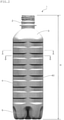
- Fig. 1 its perspective view is shown in Fig. 1 and its front view is shown in Fig. 2 .
- FIG. 3 an end face appearing on a section as a result of cutting the container 1 along a horizontal face containing the A - A line in Fig. 2 is shown in Fig. 3
- Fig. 4 an end face appearing on a section as a result of cutting the container 1 along a horizontal face containing the B - B line in Fig. 2 is shown in Fig. 4 .
- the thickness of the container 1 is omitted.
- the container 1 comprises the mouth portion 2, the shoulder portion 3, the body portion 4 and the bottom portion 5.
- the container 1 shown as one embodiment of the present invention has a container shape having the body portion 4 formed into the angular cylindrical shape, which is generally called angular bottle.
- the above-described container 1 is manufactured by molding a closed-end-cylindrical preform by using thermoplastic resin by means of injection molding or compression molding and molding this preform into a predetermined container shape by means of biaxial stretch blow molding, etc.
- thermoplastic resin When the container 1 is manufactured, any resin, which can be blow-molded, can be used as thermoplastic resin to be used.
- thermoplastic polyesters such as polyethylene terephthalate, polybutylene terephthalate, polyethylene naphthalate, acrylate polymer and polylactic acid or copolymers of these substances, the resin blended some resins of these substances, or the resin blended some resins of these substances with other resins are suitable.
- ethylene-terephthalate-based thermoplastic polyesters such as polyethylene terephthalate are suitably used.
- Polycarbonate, acrylonitrile resin, polypropylene, propylene-ethylene copolymers and polyethylene, etc. can also be used.
- the mouth portion 2 is a cylindrical site as an output port for the contents, and a nonillustrated lid member for hermetically sealing the container is attached to the mouth portion 2.
- a lower end of the mouth portion 2 has its diameter expanded toward the body portion 4 and is connected to the shoulder portion 3, which communicates the mouth portion 2 with the body portion 4.
- the shoulder portion 3 is formed to have a truncated pyramid shape.
- the body portion 4 is a site that occupies the most part of the height direction of the container 1. An upper end of the body portion 4 is connected to the shoulder portion 3 and a lower end thereof is connected to the bottom portion 5.
- the bottom portion 5 has a shape that is generally called petaloid shape in order to prevent self-standing stability from being lowered even under the positive pressure inside the container. Meanwhile, if the container 1 can stand by itself even after being filled with the contents and hermetically sealed, the shape of the bottom portion 5 is not particularly limited.
- the height direction means a direction orthogonal to a horizontal face when the container 1 is erected on the horizontal face with the mouth portion 2 upward, and the upper, lower, left, right, vertical and lateral directions of the container 1 are defined in this state.
- the cross section shape (the shape of the section orthogonal to the height direction) of the body portion 4 is square, and the body portion 4 is formed into the angular cylindrical shape having its corners round-chamfered.
- the body portion 4 also has a concave groove portion 40 formed along its circumferential direction and, in the illustrated example, the six concave groove portions 40 are disposed parallel at equal intervals along the height direction.
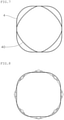
- Fig. 5 shows a state that the cross section shape (see Fig. 3 ) of the site formed into the angular cylindrical shape of the body portion 4 of the container 1 in the present embodiment and the cross section shape (see Fig. 4 ) of the site in which the concave groove portion 40 is formed are superimposed on each other.
- the concave groove portion 40 formed in the body portion 4 is formed in such a manner that the cross section shape of the site in which the concave groove portion 40 is formed is similar to the cross section shape of the site formed into the angular cylindrical shape of the body portion 4.
- the term “similar” means not only mathematical “similar” in the narrow sense, but the shapes being similar to each other.
- the cross section shape of the site in which the concave groove portion 40 is formed has only to be similar to the cross section shape of the site of the body portion 4 formed into the angular cylindrical shape, so that these shapes can be recognized to have similar polygonal shapes with the same number of sides and the same number of apexes.
- the concave groove portion 40 is formed in such a manner that the cross section shape of the site, in which the concave groove portion 40 is formed, is also the square shape.
- the concave groove portion 40 is formed in such a manner that, when the cross section shape of the site, in which the concave groove portion 40 is formed, and the cross section shape of the site formed into the angular cylindrical shape of the body portion 4 are superimposed on each other on the same plane, the respective apexes of the cross section shape of the site, in which the concave groove portion 40 is formed, internally contact with the respective sides of the cross section shape of the site formed into the angular cylindrical shape of the body portion 4 (see Fig. 5 ).
- the thus formed concave groove portion 40 is recessed to cross the respective corners of the body portion 4 and has groove bottom sections extending in a direction orthogonal to the height direction. Then, the above groove bottom sections are arranged to have square shapes with their apexes formed on the side faces of the body portion 4.
- the cross section shape of the site in which the concave groove portion 40 is formed has a relationship in the narrow sense of mathematical similar (reduction similar) with respect to the cross section shape of the site of the body portion 4 formed into the angular cylindrical shape.
- the apexes of the concave groove portion 40 is positioned at the centers of the side faces of the body portion 4 in the lateral width direction and are round-chamfered (R-chamfered with the curvature radius reduced) like the corners of the site formed into the angular cylindrical shape of the body portion 4.
- the groove bottom sections of the concave groove portion 40 is also formed planar in such a manner that the respective sides of the cross section shape of the site, in which the concave groove portion 40 is formed, are linear.
- the above-described concave groove portions 40 are formed in the body portion 4 of the container 1 having the angular cylindrical container shape, so that the deformation due to the swelling of the body portion 4 can be effectively restricted even when the positive pressure takes place inside the container. The reason therefor will be explained based on comparison with the prior art.
- the force acting on the site of the body portion 4 formed into the angular cylindrical shape is offset by the force acting on the site in which the concave groove portion 40 is formed, so that the deformation due to the swelling of the body portion 4 is restricted.
- the cross section shape of the site formed into the angular cylindrical shape of the body portion 4 and the cross section shape of the site in which the concave groove portion 40 is formed are similar to be able to recognize as the similar polygonal shapes having the same number of sides and the same number of apexes as described above, so the cross section shape of the site in which the concave groove portion 40 is formed can be appropriately modified in order to be able to offset more effectively the force acting on the site of the body portion 4 formed into the angular cylindrical shape.
- the apexes of the concave groove portions 40 may be chamfered linearly to include the surfaces flush with the side faces of the body portion 4, or the groove bottom sections of the concave groove portions 40 may be curved in such a manner that the respective sides of the cross section shape at the sites in which the concave groove portions 40 are formed are arched protruding outward from the container.
- Fig. 7 is an explanative drawing, which shows that, in the variation of the present embodiment shown in Fig. 6 , the cross section shape of the site formed into the angular cylindrical shape of the body portion 4 of the container 1 and the cross section shape of the site in which the concave groove portion 40 is formed are superimposed on each other in correspondence to Fig. 5 .
- the groove bottom sections of the concave groove portion 40 may be formed planarly so that the respective sides of the cross section shape of the site in which the concave groove portion 40 is formed are linear.
- the apexes of the concave groove portion 40 may be formed to include the surface flush with the side faces of the body portion 4 by chamfering the apexes of the concave portions 40 in C-chamfered state or by further linearly chamfering the R-chamfered apexes, for example.
- the concave groove portion 40 in such a manner that the apexes of the concave groove portion 40 lie at the centers in the lateral width directions of the side faces of the body portion 4, in order to offset the force causing to deform so that the side face of the body portion 4 is swelled outward from the container and to restrict the swelling of the side face of the body portion 4.
- the configuration is not limited to this case.
- the groove widths of the concave groove portions 40 may be made different or the intervals for the parallel arrangement may be made different depending on the positions, at which the concave groove portions 40 are formed.
- the number of concave groove portions 40 is not limited and, if the deformation due to the swelling of the body portion 4 can be restricted, at least one concave groove portion 40 has only to be formed in the body portion 4.
- the intervals for arranging the concave groove portions 40 in parallel, the groove widths of the concave groove portions 40 and the number of concave groove portions 40 can be appropriately changed depending on the volume or the size of the container 1, so that the deformation due to the swelling of the body portion 4 can be restricted.
- the container 1 shown in Figs. 1 and 2 is filled with carbonated water and hermetically sealed, so that the pressure inside the container is 0.24MPa under a condition at a temperature of 22 degrees.
- the height H of the container 1 is 206mm, the lateral width W is 60mm, the diagonal width D is 67 mm, and the ratio (D/W) of the diagonal width D to the lateral width W is 1.12 before hermetically sealing the container 1 filled with the carbonated water.
- the container 1 filled with the carbonated water and hermetically sealed is made to stand still for 24 hours in a thermostatic tank at a set temperature of 22 degrees. Thereafter, the maximum lateral width W1 and the maximum diagonal width D1 of the body portion 4 of the container 1 are measured. From the measured values, the lateral width change rate [((W1-W)/W)*100%], the diagonal width change rate [((D1-D)/D)*100%] and the ratio (D1/W1) of the maximum diagonal width D1 to the maximum lateral width W1 are obtained, and they are shown in Table 1.
- the container 1 filled with the carbonated water and hermetically sealed is made to stand still for 24 hours in the thermostatic tank at the set temperature of 37 degrees. Thereafter, as in Example 1, the lateral width change rate [((W1-W)/W)*100%], the diagonal width change rate [((D1-D)/D)*100%] and the ratio (D1/W1) of the maximum diagonal width D1 to the maximum lateral width W1 are obtained. The result thereof is shown in Table 1.
- Example 1 The same as in Example 1 applies except for using the container 1 shown in Fig. 6 .
- the lateral width change rate [((W1-W)/W)*100%], the diagonal width change rate [((D1-D)/D)*100%] and the ratio (D1/W1) of the maximum diagonal width D1 to the maximum lateral width W1 are obtained after making the container 1 stand still for 24 hours in the thermostatic tank at the set temperature of 22 degrees. The result thereof is shown in Table 1.
- Example 2 The same as in Example 2 applies except for using the container 1 shown in Fig. 6 .
- the lateral width change rate [((W1-W)/W)*100%], the diagonal width change rate [((D1-D)/D)*100%] and the ratio (D1/W1) of the maximum diagonal width D1 to the maximum lateral width W1 are obtained after making the container 1 stand still for 24 hours in the thermostatic tank at the set temperature of 37 degrees. The result thereof is shown in Table 1.
- the container 1 used in Examples 3 and 4 is identical to the one used in Examples 1 and 2 except for the former having the cross section shape of the sites in which the concave groove portions 40 are formed as shown in Fig. 7 .
- the height H is 206mm
- the lateral width W is 60mm
- the diagonal width D is 67mm
- the ratio (D/W) of the diagonal width D to the lateral width W is 1.12.
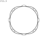
- Example 1 The same as in Example 1 applies except for using the container, in which the annular reinforcing ribs are formed in place of the concave groove portions 40 and the cross section shape of the sites in which the reinforcing ribs are formed is circular as shown in Fig. 9 .
- the lateral width change rate [((W1-W)/W)*100%], the diagonal width change rate [((D1-D)/D)*100%] and the ratio (D1/W1) of the maximum diagonal width D1 to the maximum lateral width W1 each of the container are obtained after making the container stand still for 24 hours in the thermostatic tank at the set temperature of 22 degrees. The result thereof is shown in Table 1.
- Example 2 The same as in Example 2 applies except for using the container, in which the annular reinforcing ribs are formed in place of the concave groove portions 40 and the cross section shape of the sites in which the reinforcing ribs are formed is circular as shown in Fig. 9 .
- the lateral width change rate [((W1-W)/W)*100%], the diagonal width change rate [((D1-D)/D)*100%] and the ratio (D1/W1) of the maximum diagonal width D1 to the maximum lateral width W1 each of the container are obtained after making the container stand still for 24 hours in the thermostatic tank at the set temperature of 37 degrees. The result thereof is shown in Table 1.
- the container used in Comparative Examples 1 and 2 is identical to the one used in Examples 1 and 2 except for, in the former, the annular reinforcing ribs being formed in place of the concave groove portions 40 and the cross section shape of the sites in which the reinforcing ribs are formed being circular as shown in Fig. 9 .
- the height H is 206mm
- the lateral width W is 60mm
- the diagonal width D is 67mm
- the ratio (D/W) of the diagonal width D to the lateral width W is 1.12.
- Example 1 lateral width change rate [%] Diagonal width change rate [%] Maximum diagonal width/ maximum lateral width [D1/W1]
- Example 1 1.4 0.7 1.10
- Example 2 2.1 1.0 1.10
- Example 3 0.3 0.8 1.12
- Example 4 0.9 1.1 1.12 Comparative Example 1 3.6 -0.1 1.08 Comparative Example 2 4.8 -0.1 1.07
- the container 1 having a body portion 4 with the cross section shape formed into the square angular cylindrical shape is illustrated and explained, while the illustrated examples merely show one embodiment of the present invention, and the body portion 4 can be formed into the angular cylindrical shape, so that the cross section shape is n-polygonal, where n is 3 to 12.
- the present invention can be used not only for the carbonated drinks, but also, for example, for a container having nitrogen gas, etc. sealed therein in addition to its contents, in which the positive pressure takes place.
- the synthetic resin container according to the present invention can be used for the carbonated drinks, etc., in which the positive pressure takes place inside the container after the container filled with the contents is hermetically sealed.
Landscapes
- Engineering & Computer Science (AREA)
- Mechanical Engineering (AREA)
- Ceramic Engineering (AREA)
- Manufacturing & Machinery (AREA)
- Containers Having Bodies Formed In One Piece (AREA)
Claims (7)
- Kunstharzbehälter (1), umfassend einen Öffnungsabschnitt (2), einen Schulterabschnitt (3), einen Körperabschnitt (4) und einen Bodenabschnitt (5), wobeider Körperabschnitt (4) zu einer winkligen zylindrischen Form mit einer polygonalen Querschnittsform geformt ist und einen oder mehrere konkave Rillenabschnitte (40) aufweist, die entlang einer Umfangsrichtung ausgebildet sind, dadurch gekennzeichnet, dassdie konkaven Rillenabschnitte (40) in solch einer Weise ausgebildet sind, dass:eine Querschnittsform einer Stelle, an der der konkave Rillenabschnitt (40) ausgebildet ist, ähnlich einer Querschnittsform einer Stelle ist, die in der winkligen zylindrischen Form des Körperabschnitts (4) ausgebildet ist, undwenn die Querschnittsform der Stelle, in der der konkave Rillenabschnitt (40) ausgebildet ist, und die Querschnittsform der Stelle, die in der winkligen zylindrische Form des Körperabschnitts (4) ausgebildet ist, in derselben Ebene übereinander liegen, die jeweiligen Scheitelpunkte der Querschnittsform der Stelle, in der der konkave Rillenabschnitt (40) ausgebildet ist, intern die jeweiligen Seiten der Querschnittsform der Stelle berühren, die in der winkligen zylindrischen Form des Körperabschnitts (4) ausgebildet ist.
- Kunstharzbehälter (1) nach Anspruch 1, wobei die Scheitelpunkte des konkaven Rillenabschnitts (40) an den Mittelpunkten in den seitlichen Breitenrichtungen der Seitenflächen des Körperabschnitts (4) angeordnet sind.
- Kunstharzbehälter (1) nach Anspruch 1 oder 2, wobei der konkave Rillenabschnitt (40) in solch einer Weise ausgebildet ist, dass die jeweiligen Seiten der Querschnittsform der Stelle, an der der konkave Rillenabschnitt (40) ausgebildet ist, linear oder bogenförmig nach aussen vorstehen.
- Kunstharzbehälter (1) nach irgendeinem der Ansprüche 1 bis 3, wobei die Scheitelpunkte des konkaven Rillenabschnitts (40) so abgeschrägt sind, dass sie sich in einem R-abgeschrägten Zustand befinden.
- Kunstharzbehälter (1) nach irgendeinem der Ansprüche 1 bis 3, wobei die Scheitelpunkte des konkaven Rillenabschnitts (40) Flächen aufweisen, die mit den Seitenflächen des Körperabschnitts (4) bündig sind.
- Kunstharzbehälter (1) nach Anspruch 5, wobei die Scheitelpunkte des konkaven Rillenabschnitts (40) in einem linearen Zustand oder in einem C-abgeschrägten Zustand abgeschrägt sind oder die R-abgeschrägten Scheitelpunkte weiter linear abgeschrägt sind, um die Oberflächen bündig mit den Seitenflächen des Körperabschnitts (4) zu umfassen.
- Kunstharzbehälter (1) nach irgendeinem der Ansprüche 1 bis 6, wobei der Körperabschnitt (4) zu einer winkligen zylindrischen Form geformt ist, deren Querschnittsform n-polygonal ist, wobei n 3 bis 12 ist.
Applications Claiming Priority (2)
| Application Number | Priority Date | Filing Date | Title |
|---|---|---|---|
| JP2016135886A JP6801272B2 (ja) | 2016-07-08 | 2016-07-08 | 合成樹脂製容器 |
| PCT/JP2017/023798 WO2018008494A1 (ja) | 2016-07-08 | 2017-06-28 | 合成樹脂製容器 |
Publications (3)
| Publication Number | Publication Date |
|---|---|
| EP3483081A1 EP3483081A1 (de) | 2019-05-15 |
| EP3483081A4 EP3483081A4 (de) | 2020-03-18 |
| EP3483081B1 true EP3483081B1 (de) | 2022-02-16 |
Family
ID=60912720
Family Applications (1)
| Application Number | Title | Priority Date | Filing Date |
|---|---|---|---|
| EP17824099.0A Not-in-force EP3483081B1 (de) | 2016-07-08 | 2017-06-28 | Kunstharzbehälter |
Country Status (5)
| Country | Link |
|---|---|
| US (1) | US10865008B2 (de) |
| EP (1) | EP3483081B1 (de) |
| JP (1) | JP6801272B2 (de) |
| CN (1) | CN109071060B (de) |
| WO (1) | WO2018008494A1 (de) |
Families Citing this family (6)
| Publication number | Priority date | Publication date | Assignee | Title |
|---|---|---|---|---|
| JP6597770B2 (ja) * | 2017-12-28 | 2019-10-30 | 東洋製罐株式会社 | 合成樹脂製容器 |
| JP7230407B2 (ja) * | 2018-10-01 | 2023-03-01 | 東洋製罐株式会社 | 合成樹脂製容器 |
| JP7552056B2 (ja) * | 2020-03-30 | 2024-09-18 | 東洋製罐株式会社 | 合成樹脂製容器 |
| JP7532888B2 (ja) * | 2020-05-18 | 2024-08-14 | 東洋製罐株式会社 | 合成樹脂製容器 |
| JP7681257B2 (ja) * | 2021-04-14 | 2025-05-22 | 大日本印刷株式会社 | プラスチックボトル |
| WO2023018710A1 (en) * | 2021-08-09 | 2023-02-16 | Ilc Dover Lp | Port comprising a hose barb and an elliptic body |
Family Cites Families (9)
| Publication number | Priority date | Publication date | Assignee | Title |
|---|---|---|---|---|
| JPS5026664Y1 (de) * | 1969-03-25 | 1975-08-08 | ||
| JP3388885B2 (ja) * | 1994-07-04 | 2003-03-24 | 株式会社吉野工業所 | 筒状容器 |
| JPH10264917A (ja) | 1997-03-21 | 1998-10-06 | Unitika Ltd | 耐熱・耐圧ボトル |
| WO1999008945A1 (en) * | 1997-08-19 | 1999-02-25 | Graham Packaging Company, L.P. | Distortion-resistant blow-molded plastic container |
| JP2008007147A (ja) | 2006-06-28 | 2008-01-17 | Frontier:Kk | 合成樹脂製の耐圧ボトル |
| JP5065363B2 (ja) * | 2009-12-07 | 2012-10-31 | 麒麟麦酒株式会社 | 角型飲料用プラスチック容器及びそれを用いた飲料製品 |
| JP5691028B2 (ja) * | 2009-12-25 | 2015-04-01 | サントリー食品インターナショナル株式会社 | ボトルおよび内容物入りボトル |
| US8727152B2 (en) * | 2009-12-29 | 2014-05-20 | Amcor Limited | Hot-fill container having flat panels |
| US10538357B2 (en) * | 2011-08-31 | 2020-01-21 | Amcor Rigid Plastics Usa, Llc | Lightweight container base |
-
2016
- 2016-07-08 JP JP2016135886A patent/JP6801272B2/ja active Active
-
2017
- 2017-06-28 WO PCT/JP2017/023798 patent/WO2018008494A1/ja not_active Ceased
- 2017-06-28 EP EP17824099.0A patent/EP3483081B1/de not_active Not-in-force
- 2017-06-28 US US16/312,021 patent/US10865008B2/en not_active Expired - Fee Related
- 2017-06-28 CN CN201780025598.1A patent/CN109071060B/zh not_active Expired - Fee Related
Also Published As
| Publication number | Publication date |
|---|---|
| JP6801272B2 (ja) | 2020-12-16 |
| EP3483081A1 (de) | 2019-05-15 |
| CN109071060A (zh) | 2018-12-21 |
| EP3483081A4 (de) | 2020-03-18 |
| US20190161230A1 (en) | 2019-05-30 |
| JP2018002293A (ja) | 2018-01-11 |
| CN109071060B (zh) | 2020-04-21 |
| US10865008B2 (en) | 2020-12-15 |
| WO2018008494A1 (ja) | 2018-01-11 |
Similar Documents
| Publication | Publication Date | Title |
|---|---|---|
| EP3483081B1 (de) | Kunstharzbehälter | |
| US7832583B2 (en) | Hot-fillable container and method of making | |
| US8870006B2 (en) | Hot-fill container providing vertical, vacuum compensation | |
| US9139328B2 (en) | Synthetic resin container | |
| US8276775B2 (en) | Container with at least one groove of variable depth | |
| US7780025B2 (en) | Plastic container base structure and method for hot filling a plastic container | |
| US8602237B2 (en) | Pasteurizable and hot-fillable blow molded plastic container | |
| WO2006129449A1 (ja) | 合成樹脂製壜体 | |
| JP5579376B2 (ja) | プラスチックボトル | |
| EP3290345B1 (de) | Kunstharzbehälter | |
| US20150001172A1 (en) | Load-bearing and vacuum-resistant containers | |
| AU2020201868B2 (en) | Plastic bottle | |
| AU2003266624B2 (en) | Synthetic resin bottle with grip | |
| US20120000921A1 (en) | Pressure resistant vacuum/label panel | |
| JP2010006427A (ja) | 合成樹脂製ボトル | |
| JP6060576B2 (ja) | 合成樹脂製容器 | |
| JP7003448B2 (ja) | プラスチック容器 | |
| JP2017503723A (ja) | オフセットした水平リブ及びパネルを有する耐真空容器 | |
| JP5648955B2 (ja) | 合成樹脂製壜体 | |
| JP6957978B2 (ja) | プラスチック容器 | |
| JP7230407B2 (ja) | 合成樹脂製容器 | |
| JP6759050B2 (ja) | 合成樹脂製容器 |
Legal Events
| Date | Code | Title | Description |
|---|---|---|---|
| STAA | Information on the status of an ep patent application or granted ep patent |
Free format text: STATUS: THE INTERNATIONAL PUBLICATION HAS BEEN MADE |
|
| PUAI | Public reference made under article 153(3) epc to a published international application that has entered the european phase |
Free format text: ORIGINAL CODE: 0009012 |
|
| STAA | Information on the status of an ep patent application or granted ep patent |
Free format text: STATUS: REQUEST FOR EXAMINATION WAS MADE |
|
| 17P | Request for examination filed |
Effective date: 20181207 |
|
| AK | Designated contracting states |
Kind code of ref document: A1 Designated state(s): AL AT BE BG CH CY CZ DE DK EE ES FI FR GB GR HR HU IE IS IT LI LT LU LV MC MK MT NL NO PL PT RO RS SE SI SK SM TR |
|
| AX | Request for extension of the european patent |
Extension state: BA ME |
|
| DAV | Request for validation of the european patent (deleted) | ||
| DAX | Request for extension of the european patent (deleted) | ||
| A4 | Supplementary search report drawn up and despatched |
Effective date: 20200219 |
|
| RIC1 | Information provided on ipc code assigned before grant |
Ipc: B65D 79/00 20060101ALI20200213BHEP Ipc: B65D 1/02 20060101AFI20200213BHEP |
|
| GRAP | Despatch of communication of intention to grant a patent |
Free format text: ORIGINAL CODE: EPIDOSNIGR1 |
|
| STAA | Information on the status of an ep patent application or granted ep patent |
Free format text: STATUS: GRANT OF PATENT IS INTENDED |
|
| INTG | Intention to grant announced |
Effective date: 20210920 |
|
| GRAS | Grant fee paid |
Free format text: ORIGINAL CODE: EPIDOSNIGR3 |
|
| GRAA | (expected) grant |
Free format text: ORIGINAL CODE: 0009210 |
|
| STAA | Information on the status of an ep patent application or granted ep patent |
Free format text: STATUS: THE PATENT HAS BEEN GRANTED |
|
| AK | Designated contracting states |
Kind code of ref document: B1 Designated state(s): AL AT BE BG CH CY CZ DE DK EE ES FI FR GB GR HR HU IE IS IT LI LT LU LV MC MK MT NL NO PL PT RO RS SE SI SK SM TR |
|
| REG | Reference to a national code |
Ref country code: GB Ref legal event code: FG4D |
|
| REG | Reference to a national code |
Ref country code: CH Ref legal event code: EP |
|
| REG | Reference to a national code |
Ref country code: DE Ref legal event code: R096 Ref document number: 602017053507 Country of ref document: DE |
|
| REG | Reference to a national code |
Ref country code: AT Ref legal event code: REF Ref document number: 1468738 Country of ref document: AT Kind code of ref document: T Effective date: 20220315 |
|
| REG | Reference to a national code |
Ref country code: IE Ref legal event code: FG4D |
|
| REG | Reference to a national code |
Ref country code: LT Ref legal event code: MG9D |
|
| REG | Reference to a national code |
Ref country code: NL Ref legal event code: MP Effective date: 20220216 |
|
| REG | Reference to a national code |
Ref country code: AT Ref legal event code: MK05 Ref document number: 1468738 Country of ref document: AT Kind code of ref document: T Effective date: 20220216 |
|
| PG25 | Lapsed in a contracting state [announced via postgrant information from national office to epo] |
Ref country code: SE Free format text: LAPSE BECAUSE OF FAILURE TO SUBMIT A TRANSLATION OF THE DESCRIPTION OR TO PAY THE FEE WITHIN THE PRESCRIBED TIME-LIMIT Effective date: 20220216 Ref country code: RS Free format text: LAPSE BECAUSE OF FAILURE TO SUBMIT A TRANSLATION OF THE DESCRIPTION OR TO PAY THE FEE WITHIN THE PRESCRIBED TIME-LIMIT Effective date: 20220216 Ref country code: PT Free format text: LAPSE BECAUSE OF FAILURE TO SUBMIT A TRANSLATION OF THE DESCRIPTION OR TO PAY THE FEE WITHIN THE PRESCRIBED TIME-LIMIT Effective date: 20220616 Ref country code: NO Free format text: LAPSE BECAUSE OF FAILURE TO SUBMIT A TRANSLATION OF THE DESCRIPTION OR TO PAY THE FEE WITHIN THE PRESCRIBED TIME-LIMIT Effective date: 20220516 Ref country code: NL Free format text: LAPSE BECAUSE OF FAILURE TO SUBMIT A TRANSLATION OF THE DESCRIPTION OR TO PAY THE FEE WITHIN THE PRESCRIBED TIME-LIMIT Effective date: 20220216 Ref country code: LT Free format text: LAPSE BECAUSE OF FAILURE TO SUBMIT A TRANSLATION OF THE DESCRIPTION OR TO PAY THE FEE WITHIN THE PRESCRIBED TIME-LIMIT Effective date: 20220216 Ref country code: HR Free format text: LAPSE BECAUSE OF FAILURE TO SUBMIT A TRANSLATION OF THE DESCRIPTION OR TO PAY THE FEE WITHIN THE PRESCRIBED TIME-LIMIT Effective date: 20220216 Ref country code: ES Free format text: LAPSE BECAUSE OF FAILURE TO SUBMIT A TRANSLATION OF THE DESCRIPTION OR TO PAY THE FEE WITHIN THE PRESCRIBED TIME-LIMIT Effective date: 20220216 Ref country code: BG Free format text: LAPSE BECAUSE OF FAILURE TO SUBMIT A TRANSLATION OF THE DESCRIPTION OR TO PAY THE FEE WITHIN THE PRESCRIBED TIME-LIMIT Effective date: 20220516 |
|
| PG25 | Lapsed in a contracting state [announced via postgrant information from national office to epo] |
Ref country code: PL Free format text: LAPSE BECAUSE OF FAILURE TO SUBMIT A TRANSLATION OF THE DESCRIPTION OR TO PAY THE FEE WITHIN THE PRESCRIBED TIME-LIMIT Effective date: 20220216 Ref country code: LV Free format text: LAPSE BECAUSE OF FAILURE TO SUBMIT A TRANSLATION OF THE DESCRIPTION OR TO PAY THE FEE WITHIN THE PRESCRIBED TIME-LIMIT Effective date: 20220216 Ref country code: GR Free format text: LAPSE BECAUSE OF FAILURE TO SUBMIT A TRANSLATION OF THE DESCRIPTION OR TO PAY THE FEE WITHIN THE PRESCRIBED TIME-LIMIT Effective date: 20220517 Ref country code: FI Free format text: LAPSE BECAUSE OF FAILURE TO SUBMIT A TRANSLATION OF THE DESCRIPTION OR TO PAY THE FEE WITHIN THE PRESCRIBED TIME-LIMIT Effective date: 20220216 Ref country code: AT Free format text: LAPSE BECAUSE OF FAILURE TO SUBMIT A TRANSLATION OF THE DESCRIPTION OR TO PAY THE FEE WITHIN THE PRESCRIBED TIME-LIMIT Effective date: 20220216 |
|
| PG25 | Lapsed in a contracting state [announced via postgrant information from national office to epo] |
Ref country code: IS Free format text: LAPSE BECAUSE OF FAILURE TO SUBMIT A TRANSLATION OF THE DESCRIPTION OR TO PAY THE FEE WITHIN THE PRESCRIBED TIME-LIMIT Effective date: 20220617 |
|
| PG25 | Lapsed in a contracting state [announced via postgrant information from national office to epo] |
Ref country code: SM Free format text: LAPSE BECAUSE OF FAILURE TO SUBMIT A TRANSLATION OF THE DESCRIPTION OR TO PAY THE FEE WITHIN THE PRESCRIBED TIME-LIMIT Effective date: 20220216 Ref country code: SK Free format text: LAPSE BECAUSE OF FAILURE TO SUBMIT A TRANSLATION OF THE DESCRIPTION OR TO PAY THE FEE WITHIN THE PRESCRIBED TIME-LIMIT Effective date: 20220216 Ref country code: RO Free format text: LAPSE BECAUSE OF FAILURE TO SUBMIT A TRANSLATION OF THE DESCRIPTION OR TO PAY THE FEE WITHIN THE PRESCRIBED TIME-LIMIT Effective date: 20220216 Ref country code: EE Free format text: LAPSE BECAUSE OF FAILURE TO SUBMIT A TRANSLATION OF THE DESCRIPTION OR TO PAY THE FEE WITHIN THE PRESCRIBED TIME-LIMIT Effective date: 20220216 Ref country code: DK Free format text: LAPSE BECAUSE OF FAILURE TO SUBMIT A TRANSLATION OF THE DESCRIPTION OR TO PAY THE FEE WITHIN THE PRESCRIBED TIME-LIMIT Effective date: 20220216 Ref country code: CZ Free format text: LAPSE BECAUSE OF FAILURE TO SUBMIT A TRANSLATION OF THE DESCRIPTION OR TO PAY THE FEE WITHIN THE PRESCRIBED TIME-LIMIT Effective date: 20220216 |
|
| REG | Reference to a national code |
Ref country code: DE Ref legal event code: R097 Ref document number: 602017053507 Country of ref document: DE |
|
| PG25 | Lapsed in a contracting state [announced via postgrant information from national office to epo] |
Ref country code: AL Free format text: LAPSE BECAUSE OF FAILURE TO SUBMIT A TRANSLATION OF THE DESCRIPTION OR TO PAY THE FEE WITHIN THE PRESCRIBED TIME-LIMIT Effective date: 20220216 |
|
| PLBE | No opposition filed within time limit |
Free format text: ORIGINAL CODE: 0009261 |
|
| STAA | Information on the status of an ep patent application or granted ep patent |
Free format text: STATUS: NO OPPOSITION FILED WITHIN TIME LIMIT |
|
| 26N | No opposition filed |
Effective date: 20221117 |
|
| PG25 | Lapsed in a contracting state [announced via postgrant information from national office to epo] |
Ref country code: MC Free format text: LAPSE BECAUSE OF FAILURE TO SUBMIT A TRANSLATION OF THE DESCRIPTION OR TO PAY THE FEE WITHIN THE PRESCRIBED TIME-LIMIT Effective date: 20220216 |
|
| REG | Reference to a national code |
Ref country code: CH Ref legal event code: PL |
|
| REG | Reference to a national code |
Ref country code: BE Ref legal event code: MM Effective date: 20220630 |
|
| PG25 | Lapsed in a contracting state [announced via postgrant information from national office to epo] |
Ref country code: SI Free format text: LAPSE BECAUSE OF FAILURE TO SUBMIT A TRANSLATION OF THE DESCRIPTION OR TO PAY THE FEE WITHIN THE PRESCRIBED TIME-LIMIT Effective date: 20220216 |
|
| GBPC | Gb: european patent ceased through non-payment of renewal fee |
Effective date: 20220628 |
|
| PG25 | Lapsed in a contracting state [announced via postgrant information from national office to epo] |
Ref country code: LU Free format text: LAPSE BECAUSE OF NON-PAYMENT OF DUE FEES Effective date: 20220628 Ref country code: LI Free format text: LAPSE BECAUSE OF NON-PAYMENT OF DUE FEES Effective date: 20220630 Ref country code: IE Free format text: LAPSE BECAUSE OF NON-PAYMENT OF DUE FEES Effective date: 20220628 Ref country code: CH Free format text: LAPSE BECAUSE OF NON-PAYMENT OF DUE FEES Effective date: 20220630 |
|
| PG25 | Lapsed in a contracting state [announced via postgrant information from national office to epo] |
Ref country code: GB Free format text: LAPSE BECAUSE OF NON-PAYMENT OF DUE FEES Effective date: 20220628 Ref country code: BE Free format text: LAPSE BECAUSE OF NON-PAYMENT OF DUE FEES Effective date: 20220630 |
|
| PG25 | Lapsed in a contracting state [announced via postgrant information from national office to epo] |
Ref country code: IT Free format text: LAPSE BECAUSE OF FAILURE TO SUBMIT A TRANSLATION OF THE DESCRIPTION OR TO PAY THE FEE WITHIN THE PRESCRIBED TIME-LIMIT Effective date: 20220216 |
|
| PGFP | Annual fee paid to national office [announced via postgrant information from national office to epo] |
Ref country code: FR Payment date: 20230628 Year of fee payment: 7 Ref country code: DE Payment date: 20230620 Year of fee payment: 7 |
|
| PG25 | Lapsed in a contracting state [announced via postgrant information from national office to epo] |
Ref country code: HU Free format text: LAPSE BECAUSE OF FAILURE TO SUBMIT A TRANSLATION OF THE DESCRIPTION OR TO PAY THE FEE WITHIN THE PRESCRIBED TIME-LIMIT; INVALID AB INITIO Effective date: 20170628 |
|
| PG25 | Lapsed in a contracting state [announced via postgrant information from national office to epo] |
Ref country code: MK Free format text: LAPSE BECAUSE OF FAILURE TO SUBMIT A TRANSLATION OF THE DESCRIPTION OR TO PAY THE FEE WITHIN THE PRESCRIBED TIME-LIMIT Effective date: 20220216 Ref country code: CY Free format text: LAPSE BECAUSE OF FAILURE TO SUBMIT A TRANSLATION OF THE DESCRIPTION OR TO PAY THE FEE WITHIN THE PRESCRIBED TIME-LIMIT Effective date: 20220216 |
|
| PG25 | Lapsed in a contracting state [announced via postgrant information from national office to epo] |
Ref country code: MT Free format text: LAPSE BECAUSE OF FAILURE TO SUBMIT A TRANSLATION OF THE DESCRIPTION OR TO PAY THE FEE WITHIN THE PRESCRIBED TIME-LIMIT Effective date: 20220216 |
|
| REG | Reference to a national code |
Ref country code: DE Ref legal event code: R119 Ref document number: 602017053507 Country of ref document: DE |
|
| PG25 | Lapsed in a contracting state [announced via postgrant information from national office to epo] |
Ref country code: DE Free format text: LAPSE BECAUSE OF NON-PAYMENT OF DUE FEES Effective date: 20250101 |
|
| PG25 | Lapsed in a contracting state [announced via postgrant information from national office to epo] |
Ref country code: FR Free format text: LAPSE BECAUSE OF NON-PAYMENT OF DUE FEES Effective date: 20240630 |
|
| PG25 | Lapsed in a contracting state [announced via postgrant information from national office to epo] |
Ref country code: TR Free format text: LAPSE BECAUSE OF FAILURE TO SUBMIT A TRANSLATION OF THE DESCRIPTION OR TO PAY THE FEE WITHIN THE PRESCRIBED TIME-LIMIT Effective date: 20220216 |