EP3483146B1 - Heterocyclische verbindung und organische lichtemittierende vorrichtung damit - Google Patents
Heterocyclische verbindung und organische lichtemittierende vorrichtung damit Download PDFInfo
- Publication number
- EP3483146B1 EP3483146B1 EP17824563.5A EP17824563A EP3483146B1 EP 3483146 B1 EP3483146 B1 EP 3483146B1 EP 17824563 A EP17824563 A EP 17824563A EP 3483146 B1 EP3483146 B1 EP 3483146B1
- Authority
- EP
- European Patent Office
- Prior art keywords
- group
- light emitting
- layer
- substituted
- unsubstituted
- Prior art date
- Legal status (The legal status is an assumption and is not a legal conclusion. Google has not performed a legal analysis and makes no representation as to the accuracy of the status listed.)
- Active
Links
- 0 O=P(c1ccccc1)(c1ccccc1)c1cc(C(*2)C=C(c3ccccc3)c3c2ccc2ccccc32)ccc1 Chemical compound O=P(c1ccccc1)(c1ccccc1)c1cc(C(*2)C=C(c3ccccc3)c3c2ccc2ccccc32)ccc1 0.000 description 18
- CQMXXCVNOVNHGU-UHFFFAOYSA-N c(cc1)ccc1-c(cc1)ccc1-c1nc(-c2ccccc2)nc(-c2cc(-c3cc(-c4ccccc4)c(c4ccccc4cc4)c4n3)cc(-c(cc3)cc4c3[o]c3ccccc43)c2)n1 Chemical compound c(cc1)ccc1-c(cc1)ccc1-c1nc(-c2ccccc2)nc(-c2cc(-c3cc(-c4ccccc4)c(c4ccccc4cc4)c4n3)cc(-c(cc3)cc4c3[o]c3ccccc43)c2)n1 CQMXXCVNOVNHGU-UHFFFAOYSA-N 0.000 description 2
- DEQUOCWWFLBBTP-UHFFFAOYSA-N c(cc1)ccc1-c(cc1)ccc1-c1nc(-c2ccccc2)nc(-c2cc(-c3cc(-c4ccccc4)c(c4ccccc4cc4)c4n3)cc(-c3c(c4ccccc4[o]4)c4ccc3)c2)n1 Chemical compound c(cc1)ccc1-c(cc1)ccc1-c1nc(-c2ccccc2)nc(-c2cc(-c3cc(-c4ccccc4)c(c4ccccc4cc4)c4n3)cc(-c3c(c4ccccc4[o]4)c4ccc3)c2)n1 DEQUOCWWFLBBTP-UHFFFAOYSA-N 0.000 description 2
- HJMBIPXZFAVJOG-UHFFFAOYSA-N c(cc1)ccc1-c(cc1)ccc1-c1nc(-c2ccccc2)nc(-c2cc(-c3cccc4c3[o]c3c4cccc3)cc(-c3cc(-c4ccccc4)c(c4ccccc4cc4)c4n3)c2)n1 Chemical compound c(cc1)ccc1-c(cc1)ccc1-c1nc(-c2ccccc2)nc(-c2cc(-c3cccc4c3[o]c3c4cccc3)cc(-c3cc(-c4ccccc4)c(c4ccccc4cc4)c4n3)c2)n1 HJMBIPXZFAVJOG-UHFFFAOYSA-N 0.000 description 2
- WSXOYEUQZXWFTJ-UHFFFAOYSA-N c(cc1)ccc1-c(cc1)ccc1-c1nc(-c2ccccc2)nc(-c2cc(-c3cccc4c3[s]c3c4cccc3)cc(-c3cc(-c4ccccc4)c(c4ccccc4cc4)c4n3)c2)n1 Chemical compound c(cc1)ccc1-c(cc1)ccc1-c1nc(-c2ccccc2)nc(-c2cc(-c3cccc4c3[s]c3c4cccc3)cc(-c3cc(-c4ccccc4)c(c4ccccc4cc4)c4n3)c2)n1 WSXOYEUQZXWFTJ-UHFFFAOYSA-N 0.000 description 2
- PLFPHZSTDZOROO-UHFFFAOYSA-N c(cc1)ccc1-c1c(c(cccc2)c2cc2)c2nc(-c2cccc(-c(cc3)ccc3-c3nc(-c4ccncc4)nc(-c4ccncc4)n3)c2)c1 Chemical compound c(cc1)ccc1-c1c(c(cccc2)c2cc2)c2nc(-c2cccc(-c(cc3)ccc3-c3nc(-c4ccncc4)nc(-c4ccncc4)n3)c2)c1 PLFPHZSTDZOROO-UHFFFAOYSA-N 0.000 description 2
- GZHKGZBSVSRLLB-UHFFFAOYSA-N c(cc1)ccc1-c1c(c2ccccc2cc2)c2nc(-c2cccc(-c(cc3)ccc3-c3nc(-c4ncccc4)nc(-c4ccccn4)n3)c2)c1 Chemical compound c(cc1)ccc1-c1c(c2ccccc2cc2)c2nc(-c2cccc(-c(cc3)ccc3-c3nc(-c4ncccc4)nc(-c4ccccn4)n3)c2)c1 GZHKGZBSVSRLLB-UHFFFAOYSA-N 0.000 description 2
- WZUKSSXBNNXWGL-UHFFFAOYSA-N c(cc1)ccc1-c1cc(-c2cc(-c3nc(-c4cccc5c4cccc5)nc(-c4c(cccc5)c5ccc4)c3)ccc2)c(c2ccccc2cc2)c2n1 Chemical compound c(cc1)ccc1-c1cc(-c2cc(-c3nc(-c4cccc5c4cccc5)nc(-c4c(cccc5)c5ccc4)c3)ccc2)c(c2ccccc2cc2)c2n1 WZUKSSXBNNXWGL-UHFFFAOYSA-N 0.000 description 2
- VEGIRWRGBPDASS-UHFFFAOYSA-N c(cc1)ccc1-c1cc(-c2cc(-c3nc(-c4ncccc4)nc(-c4ccccn4)c3)ccc2)c(c2ccccc2cc2)c2n1 Chemical compound c(cc1)ccc1-c1cc(-c2cc(-c3nc(-c4ncccc4)nc(-c4ccccn4)c3)ccc2)c(c2ccccc2cc2)c2n1 VEGIRWRGBPDASS-UHFFFAOYSA-N 0.000 description 2
- ZYGCFZJBWHEDBH-UHFFFAOYSA-N c(cc1)ccc1-c1cccc(-c2nc(-c(cc3)ccc3-c3cccc(-c4nc(ccc5ccccc55)c5c(-c5ccccc5)c4)c3)nc(-c3cc(-c4ccccc4)ccc3)n2)c1 Chemical compound c(cc1)ccc1-c1cccc(-c2nc(-c(cc3)ccc3-c3cccc(-c4nc(ccc5ccccc55)c5c(-c5ccccc5)c4)c3)nc(-c3cc(-c4ccccc4)ccc3)n2)c1 ZYGCFZJBWHEDBH-UHFFFAOYSA-N 0.000 description 2
- SJOKONNBSXFPSN-UHFFFAOYSA-N Brc1cc(-[n]2c(cccc3)c3c3c2cccc3)cc(-[n]2c3ccccc3c3c2cccc3)c1 Chemical compound Brc1cc(-[n]2c(cccc3)c3c3c2cccc3)cc(-[n]2c3ccccc3c3c2cccc3)c1 SJOKONNBSXFPSN-UHFFFAOYSA-N 0.000 description 1
- PTPGZCQGDXUUAH-UHFFFAOYSA-N Brc1nc(-c2ccccc2)nc(-c2ccccc2)n1 Chemical compound Brc1nc(-c2ccccc2)nc(-c2ccccc2)n1 PTPGZCQGDXUUAH-UHFFFAOYSA-N 0.000 description 1
- BXYQBNSWNGIFKE-UHFFFAOYSA-N CC(C1)C=Cc2c1c(-c1nc(-c3c(cccc4)c4ccc3)cc(-c(cc3)ccc3-c(cc3)ccc3-c3c(c4ccccc4cc4)c4nc(-c4ccccc4)c3)n1)ccc2 Chemical compound CC(C1)C=Cc2c1c(-c1nc(-c3c(cccc4)c4ccc3)cc(-c(cc3)ccc3-c(cc3)ccc3-c3c(c4ccccc4cc4)c4nc(-c4ccccc4)c3)n1)ccc2 BXYQBNSWNGIFKE-UHFFFAOYSA-N 0.000 description 1
- OJCHNLVSRAKVNJ-UHFFFAOYSA-N CC(Cc1c2c(-c3cc(-c(c4c5cccc4)ccc5-c4nc(-c5c(cccc6)c6ccc5)nc(-c5cccc6c5cccc6)n4)ccc3)c3)C=Cc1ccc2nc3-c1ccccc1 Chemical compound CC(Cc1c2c(-c3cc(-c(c4c5cccc4)ccc5-c4nc(-c5c(cccc6)c6ccc5)nc(-c5cccc6c5cccc6)n4)ccc3)c3)C=Cc1ccc2nc3-c1ccccc1 OJCHNLVSRAKVNJ-UHFFFAOYSA-N 0.000 description 1
- FEIGWBTVVVROKV-UHFFFAOYSA-N CC1C(C2)C2(C2)C2C1 Chemical compound CC1C(C2)C2(C2)C2C1 FEIGWBTVVVROKV-UHFFFAOYSA-N 0.000 description 1
- XBWIXBGQUUAHDQ-UHFFFAOYSA-N CC1C(C2)[O]2(C)(C)CCB1 Chemical compound CC1C(C2)[O]2(C)(C)CCB1 XBWIXBGQUUAHDQ-UHFFFAOYSA-N 0.000 description 1
- YFPWVSPFADYJPB-ROQFLVNWSA-N CCC(c1cccc(-c2ccccc2)c1)/N=C(\C=C(\c(cc1)ccc1-c(cc1)ccc1-c1c(c2ccccc2cc2)c2nc(-c2ccccc2)c1)/N)/c1cc(-c2ccccc2)ccc1 Chemical compound CCC(c1cccc(-c2ccccc2)c1)/N=C(\C=C(\c(cc1)ccc1-c(cc1)ccc1-c1c(c2ccccc2cc2)c2nc(-c2ccccc2)c1)/N)/c1cc(-c2ccccc2)ccc1 YFPWVSPFADYJPB-ROQFLVNWSA-N 0.000 description 1
- BSKOLJVTLRLTHE-UHFFFAOYSA-N CCC1C(C)CCC1 Chemical compound CCC1C(C)CCC1 BSKOLJVTLRLTHE-UHFFFAOYSA-N 0.000 description 1
- MZZWYXWQQRAKGF-UHFFFAOYSA-N O=[O](c1ccccc1)(c1ccccc1)c1ccc(-c2cccc(-c3cc(-c4ccccc4)nc4ccc(cccc5)c5c34)c2)c2c1cccc2 Chemical compound O=[O](c1ccccc1)(c1ccccc1)c1ccc(-c2cccc(-c3cc(-c4ccccc4)nc4ccc(cccc5)c5c34)c2)c2c1cccc2 MZZWYXWQQRAKGF-UHFFFAOYSA-N 0.000 description 1
- ZXHMKXROTFNDFR-UHFFFAOYSA-N c(cc1)ccc1-c(cc1)ccc1-c1nc(-c(cc2)c(cccc3)c3c2-c(cc2)ccc2-c2cc(-c3ccccc3)c(c3ccccc3cc3)c3n2)nc(-c2ccccc2)n1 Chemical compound c(cc1)ccc1-c(cc1)ccc1-c1nc(-c(cc2)c(cccc3)c3c2-c(cc2)ccc2-c2cc(-c3ccccc3)c(c3ccccc3cc3)c3n2)nc(-c2ccccc2)n1 ZXHMKXROTFNDFR-UHFFFAOYSA-N 0.000 description 1
- IHGWSXMIEQDJFN-UHFFFAOYSA-N c(cc1)ccc1-c(cc1)ccc1-c1nc(-c(cc2)ccc2-c(cc2)ccc2-c2c(c3ccccc3cc3)c3nc(-c3ccccc3)c2)nc(-c2ccccc2)n1 Chemical compound c(cc1)ccc1-c(cc1)ccc1-c1nc(-c(cc2)ccc2-c(cc2)ccc2-c2c(c3ccccc3cc3)c3nc(-c3ccccc3)c2)nc(-c2ccccc2)n1 IHGWSXMIEQDJFN-UHFFFAOYSA-N 0.000 description 1
- JMZSNKSDOLITSJ-UHFFFAOYSA-N c(cc1)ccc1-c(cc1)ccc1-c1nc(-c(cc2)ccc2-c2cc(-c3ccccc3)c(c3ccccc3cc3)c3n2)nc(-c(cc2)ccc2-c2ccccc2)n1 Chemical compound c(cc1)ccc1-c(cc1)ccc1-c1nc(-c(cc2)ccc2-c2cc(-c3ccccc3)c(c3ccccc3cc3)c3n2)nc(-c(cc2)ccc2-c2ccccc2)n1 JMZSNKSDOLITSJ-UHFFFAOYSA-N 0.000 description 1
- JGNCNHNGIUSMLI-UHFFFAOYSA-N c(cc1)ccc1-c(cc1)ccc1-c1nc(-c(cc2)ccc2-c2cccc(-c3cc(-c4ccccc4)c(c4c(cc5)c(-c(cc6)cc7c6ccc(-c6nc(-c8cc9ccccc9cc8)nc(-c(cc8)ccc8-c8cccc(-c9cc(-c%10ccccc%10)c(c%10c(cc%11)c(-c(c%12ccc%13)cccc%12c%13-c%12nc(-c%13c(cccc%14)c%14ccc%13)nc(-c(cc%13)ccc%13-c%13cc(-c%14nc%15ccc(cccc%16)c%16c%15c(-c%15ccccc%15)c%14)ccc%13)n%12)ccc%10)c%11n9)c8)n6)c7)ccc4)c5n3)c2)nc(-c(cc2)ccc2-c2ccccc2)n1 Chemical compound c(cc1)ccc1-c(cc1)ccc1-c1nc(-c(cc2)ccc2-c2cccc(-c3cc(-c4ccccc4)c(c4c(cc5)c(-c(cc6)cc7c6ccc(-c6nc(-c8cc9ccccc9cc8)nc(-c(cc8)ccc8-c8cccc(-c9cc(-c%10ccccc%10)c(c%10c(cc%11)c(-c(c%12ccc%13)cccc%12c%13-c%12nc(-c%13c(cccc%14)c%14ccc%13)nc(-c(cc%13)ccc%13-c%13cc(-c%14nc%15ccc(cccc%16)c%16c%15c(-c%15ccccc%15)c%14)ccc%13)n%12)ccc%10)c%11n9)c8)n6)c7)ccc4)c5n3)c2)nc(-c(cc2)ccc2-c2ccccc2)n1 JGNCNHNGIUSMLI-UHFFFAOYSA-N 0.000 description 1
- FQXGYARZYOFSAM-UHFFFAOYSA-N c(cc1)ccc1-c(cc1)ccc1-c1nc(-c(cc2)ccc2-c2ccccc2)nc(-c(cc2)c(cccc3)c3c2-c(cc2)ccc2-c2cc(-c3ccccc3)c(c(cccc3)c3cc3)c3n2)n1 Chemical compound c(cc1)ccc1-c(cc1)ccc1-c1nc(-c(cc2)ccc2-c2ccccc2)nc(-c(cc2)c(cccc3)c3c2-c(cc2)ccc2-c2cc(-c3ccccc3)c(c(cccc3)c3cc3)c3n2)n1 FQXGYARZYOFSAM-UHFFFAOYSA-N 0.000 description 1
- GWBIUANHMABAQB-UHFFFAOYSA-N c(cc1)ccc1-c(cc1)ccc1-c1nc(-c(cc2)ccc2-c2ccccc2)nc(-c(cc2)ccc2-c(cc2)ccc2-c2nc(ccc3c4cccc3)c4c(-c(cc3)ccc3-c(cc3)cc(cc4)c3cc4-c3nc(-c4cc(cccc5)c5cc4)nc(-c(cc4)ccc4-c(cc4)ccc4-c4cc(-c5ccccc5)c(c(cccc5)c5cc5)c5n4)n3)c2)n1 Chemical compound c(cc1)ccc1-c(cc1)ccc1-c1nc(-c(cc2)ccc2-c2ccccc2)nc(-c(cc2)ccc2-c(cc2)ccc2-c2nc(ccc3c4cccc3)c4c(-c(cc3)ccc3-c(cc3)cc(cc4)c3cc4-c3nc(-c4cc(cccc5)c5cc4)nc(-c(cc4)ccc4-c(cc4)ccc4-c4cc(-c5ccccc5)c(c(cccc5)c5cc5)c5n4)n3)c2)n1 GWBIUANHMABAQB-UHFFFAOYSA-N 0.000 description 1
- GMJJJOIJVLTFGK-UHFFFAOYSA-N c(cc1)ccc1-c(cc1)ccc1-c1nc(-c(cc2)ccc2-c2nc3ccc(cccc4)c4c3c(-c3ccccc3)c2)nc(-c2ccccc2)n1 Chemical compound c(cc1)ccc1-c(cc1)ccc1-c1nc(-c(cc2)ccc2-c2nc3ccc(cccc4)c4c3c(-c3ccccc3)c2)nc(-c2ccccc2)n1 GMJJJOIJVLTFGK-UHFFFAOYSA-N 0.000 description 1
- ZPLMPAUOJLZSLV-UHFFFAOYSA-N c(cc1)ccc1-c(cc1)ccc1-c1nc(-c2cc(-c3nc4ccc(cccc5)c5c4c(-c4ccccc4)c3)ccc2)nc(-c2ccccc2)n1 Chemical compound c(cc1)ccc1-c(cc1)ccc1-c1nc(-c2cc(-c3nc4ccc(cccc5)c5c4c(-c4ccccc4)c3)ccc2)nc(-c2ccccc2)n1 ZPLMPAUOJLZSLV-UHFFFAOYSA-N 0.000 description 1
- CBXCRYVLXQTXBA-UHFFFAOYSA-N c(cc1)ccc1-c(cc1)ccc1-c1nc(-c2ccc(-c3cccc(-c4cc(-c5ccccc5)nc5c4c(cccc4)c4cc5)c3)c3c2cccc3)nc(-c(cc2)ccc2-c2ccccc2)n1 Chemical compound c(cc1)ccc1-c(cc1)ccc1-c1nc(-c2ccc(-c3cccc(-c4cc(-c5ccccc5)nc5c4c(cccc4)c4cc5)c3)c3c2cccc3)nc(-c(cc2)ccc2-c2ccccc2)n1 CBXCRYVLXQTXBA-UHFFFAOYSA-N 0.000 description 1
- CPYMLVMOWWOHFU-UHFFFAOYSA-N c(cc1)ccc1-c(cc1)ccc1-c1nc(-c2cccc(-c3nc4ccc(cccc5)c5c4c(-c4ccccc4)c3)c2)nc(-c(cc2)ccc2-c2ccccc2)n1 Chemical compound c(cc1)ccc1-c(cc1)ccc1-c1nc(-c2cccc(-c3nc4ccc(cccc5)c5c4c(-c4ccccc4)c3)c2)nc(-c(cc2)ccc2-c2ccccc2)n1 CPYMLVMOWWOHFU-UHFFFAOYSA-N 0.000 description 1
- XCYMPSKDZPWUET-UHFFFAOYSA-N c(cc1)ccc1-c(cc1)ccc1-c1nc(-c2ccccc2)nc(-c2cc(-c3cc(-c4ccccc4)c(c4ccccc4cc4)c4n3)cc(-c(cc3)cc4c3[o]c3ccccc43)c2)c1 Chemical compound c(cc1)ccc1-c(cc1)ccc1-c1nc(-c2ccccc2)nc(-c2cc(-c3cc(-c4ccccc4)c(c4ccccc4cc4)c4n3)cc(-c(cc3)cc4c3[o]c3ccccc43)c2)c1 XCYMPSKDZPWUET-UHFFFAOYSA-N 0.000 description 1
- XIHVRTKBXGCZRX-UHFFFAOYSA-N c(cc1)ccc1-c(cc1)ccc1-c1nc(-c2ccccc2)nc(-c2cc(-c3cc(-c4ccccc4)c(c4ccccc4cc4)c4n3)cc(-c3c(c4ccccc4[o]4)c4ccc3)c2)c1 Chemical compound c(cc1)ccc1-c(cc1)ccc1-c1nc(-c2ccccc2)nc(-c2cc(-c3cc(-c4ccccc4)c(c4ccccc4cc4)c4n3)cc(-c3c(c4ccccc4[o]4)c4ccc3)c2)c1 XIHVRTKBXGCZRX-UHFFFAOYSA-N 0.000 description 1
- MOFFCFXUGIVKPG-UHFFFAOYSA-N c(cc1)ccc1-c(cc1)ccc1-c1nc(-c2ccccc2)nc(-c2cc(-c3cc(-c4ccccc4)c(c4ccccc4cc4)c4n3)cc(-c3cccc4c3[s]c3c4cccc3)c2)c1 Chemical compound c(cc1)ccc1-c(cc1)ccc1-c1nc(-c2ccccc2)nc(-c2cc(-c3cc(-c4ccccc4)c(c4ccccc4cc4)c4n3)cc(-c3cccc4c3[s]c3c4cccc3)c2)c1 MOFFCFXUGIVKPG-UHFFFAOYSA-N 0.000 description 1
- ABWGCMQHNZQHKT-UHFFFAOYSA-N c(cc1)ccc1-c(cc1)ccc1-c1nc(-c2ccccc2)nc(-c2cc(-c3cccc4c3[o]c3c4cccc3)cc(-c3cc(-c4ccccc4)c(c4ccccc4cc4)c4n3)c2)c1 Chemical compound c(cc1)ccc1-c(cc1)ccc1-c1nc(-c2ccccc2)nc(-c2cc(-c3cccc4c3[o]c3c4cccc3)cc(-c3cc(-c4ccccc4)c(c4ccccc4cc4)c4n3)c2)c1 ABWGCMQHNZQHKT-UHFFFAOYSA-N 0.000 description 1
- KVMSKHVATPISBR-UHFFFAOYSA-N c(cc1)ccc1-c(ccc1ccc2cc3)nc1c2nc3-c1ccc(-c(cc2)ccc2-c2c(c3ccccc3cc3)c3nc(-c3ccccc3)c2)c2c1cccc2 Chemical compound c(cc1)ccc1-c(ccc1ccc2cc3)nc1c2nc3-c1ccc(-c(cc2)ccc2-c2c(c3ccccc3cc3)c3nc(-c3ccccc3)c2)c2c1cccc2 KVMSKHVATPISBR-UHFFFAOYSA-N 0.000 description 1
- LBYCUDDVYAZQTC-UHFFFAOYSA-N c(cc1)ccc1-c1c(c(cccc2)c2cc2)c2nc(-c(cc2)ccc2-c2cc(-[n]3c(cccc4)c4c4c3cccc4)cc(-[n]3c4ccccc4c4c3cccc4)c2)c1 Chemical compound c(cc1)ccc1-c1c(c(cccc2)c2cc2)c2nc(-c(cc2)ccc2-c2cc(-[n]3c(cccc4)c4c4c3cccc4)cc(-[n]3c4ccccc4c4c3cccc4)c2)c1 LBYCUDDVYAZQTC-UHFFFAOYSA-N 0.000 description 1
- GWCQEKNBFBIJTM-UHFFFAOYSA-N c(cc1)ccc1-c1c(c2ccccc2cc2)c2nc(-c(cc2)ccc2-c(c2c3cccc2)ccc3-c2nc(-c3cc(cccc4)c4cc3)nc(-c3cc(cccc4)c4cc3)n2)c1 Chemical compound c(cc1)ccc1-c1c(c2ccccc2cc2)c2nc(-c(cc2)ccc2-c(c2c3cccc2)ccc3-c2nc(-c3cc(cccc4)c4cc3)nc(-c3cc(cccc4)c4cc3)n2)c1 GWCQEKNBFBIJTM-UHFFFAOYSA-N 0.000 description 1
- ORLGGQJZWYQDKI-UHFFFAOYSA-N c(cc1)ccc1-c1c(c2ccccc2cc2)c2nc(-c(cc2)ccc2-c(cc2)c(cccc3)c3c2-c2cc(-c3ccccn3)nc(-c3ncccc3)c2)c1 Chemical compound c(cc1)ccc1-c1c(c2ccccc2cc2)c2nc(-c(cc2)ccc2-c(cc2)c(cccc3)c3c2-c2cc(-c3ccccn3)nc(-c3ncccc3)c2)c1 ORLGGQJZWYQDKI-UHFFFAOYSA-N 0.000 description 1
- GYKHRKVMMPJYQR-UHFFFAOYSA-N c(cc1)ccc1-c1c(c2ccccc2cc2)c2nc(-c(cc2)ccc2-c(cc2)c(cccc3)c3c2-c2nc(-c3ccccc3)nc(-c3ccccc3)n2)c1 Chemical compound c(cc1)ccc1-c1c(c2ccccc2cc2)c2nc(-c(cc2)ccc2-c(cc2)c(cccc3)c3c2-c2nc(-c3ccccc3)nc(-c3ccccc3)n2)c1 GYKHRKVMMPJYQR-UHFFFAOYSA-N 0.000 description 1
- LEPKJGROOVGOIA-UHFFFAOYSA-N c(cc1)ccc1-c1c(c2ccccc2cc2)c2nc(-c(cc2)ccc2-c(cc2)c(cccc3)c3c2-c2nc(-c3ccccn3)nc(-c3ccccn3)c2)c1 Chemical compound c(cc1)ccc1-c1c(c2ccccc2cc2)c2nc(-c(cc2)ccc2-c(cc2)c(cccc3)c3c2-c2nc(-c3ccccn3)nc(-c3ccccn3)c2)c1 LEPKJGROOVGOIA-UHFFFAOYSA-N 0.000 description 1
- NTBJTYWZYJJUPK-UHFFFAOYSA-N c(cc1)ccc1-c1c(c2ccccc2cc2)c2nc(-c(cc2)ccc2-c(cc2)c(cccc3)c3c2-c2nc(-c3cccnc3)nc(-c3cccnc3)n2)c1 Chemical compound c(cc1)ccc1-c1c(c2ccccc2cc2)c2nc(-c(cc2)ccc2-c(cc2)c(cccc3)c3c2-c2nc(-c3cccnc3)nc(-c3cccnc3)n2)c1 NTBJTYWZYJJUPK-UHFFFAOYSA-N 0.000 description 1
- TVKIBYUZPNBGFZ-UHFFFAOYSA-N c(cc1)ccc1-c1c(c2ccccc2cc2)c2nc(-c(cc2)ccc2-c(cc2)c(cccc3)c3c2-c2nc(-c3ccncc3)nc(-c3ccncc3)c2)c1 Chemical compound c(cc1)ccc1-c1c(c2ccccc2cc2)c2nc(-c(cc2)ccc2-c(cc2)c(cccc3)c3c2-c2nc(-c3ccncc3)nc(-c3ccncc3)c2)c1 TVKIBYUZPNBGFZ-UHFFFAOYSA-N 0.000 description 1
- YNPAUAPTEHHCGG-UHFFFAOYSA-N c(cc1)ccc1-c1c(c2ccccc2cc2)c2nc(-c(cc2)ccc2-c(cc2)c(cccc3)c3c2-c2nc(-c3ccncc3)nc(-c3ccncc3)n2)c1 Chemical compound c(cc1)ccc1-c1c(c2ccccc2cc2)c2nc(-c(cc2)ccc2-c(cc2)c(cccc3)c3c2-c2nc(-c3ccncc3)nc(-c3ccncc3)n2)c1 YNPAUAPTEHHCGG-UHFFFAOYSA-N 0.000 description 1
- HSGKXSDHLWAYSA-UHFFFAOYSA-N c(cc1)ccc1-c1c(c2ccccc2cc2)c2nc(-c(cc2)ccc2-c(cc2)ccc2-c(c2c3nccc2)cc2c3nccc2)c1 Chemical compound c(cc1)ccc1-c1c(c2ccccc2cc2)c2nc(-c(cc2)ccc2-c(cc2)ccc2-c(c2c3nccc2)cc2c3nccc2)c1 HSGKXSDHLWAYSA-UHFFFAOYSA-N 0.000 description 1
- WWGLISLDRHWLEW-UHFFFAOYSA-N c(cc1)ccc1-c1c(c2ccccc2cc2)c2nc(-c(cc2)ccc2-c(cc2)ccc2-c2nc(-c3c(cccc4)c4ccc3)nc(-c3c(cccc4)c4ccc3)n2)c1 Chemical compound c(cc1)ccc1-c1c(c2ccccc2cc2)c2nc(-c(cc2)ccc2-c(cc2)ccc2-c2nc(-c3c(cccc4)c4ccc3)nc(-c3c(cccc4)c4ccc3)n2)c1 WWGLISLDRHWLEW-UHFFFAOYSA-N 0.000 description 1
- DGGACHRLHDJFOY-UHFFFAOYSA-N c(cc1)ccc1-c1c(c2ccccc2cc2)c2nc(-c(cc2)ccc2-c(ccc2ccc3cc4)nc2c3nc4-c2ccccc2)c1 Chemical compound c(cc1)ccc1-c1c(c2ccccc2cc2)c2nc(-c(cc2)ccc2-c(ccc2ccc3cc4)nc2c3nc4-c2ccccc2)c1 DGGACHRLHDJFOY-UHFFFAOYSA-N 0.000 description 1
- XVTIZTAPIIPOLU-UHFFFAOYSA-N c(cc1)ccc1-c1c(c2ccccc2cc2)c2nc(-c(cc2)ccc2-c2nc(-c3ccccn3)nc(-c3ccccn3)c2)c1 Chemical compound c(cc1)ccc1-c1c(c2ccccc2cc2)c2nc(-c(cc2)ccc2-c2nc(-c3ccccn3)nc(-c3ccccn3)c2)c1 XVTIZTAPIIPOLU-UHFFFAOYSA-N 0.000 description 1
- QYZZEXHMVKEZJM-UHFFFAOYSA-N c(cc1)ccc1-c1c(c2ccccc2cc2)c2nc(-c(cc2)ccc2-c2nc(-c3ccccn3)nc(-c3ccccn3)n2)c1 Chemical compound c(cc1)ccc1-c1c(c2ccccc2cc2)c2nc(-c(cc2)ccc2-c2nc(-c3ccccn3)nc(-c3ccccn3)n2)c1 QYZZEXHMVKEZJM-UHFFFAOYSA-N 0.000 description 1
- OSALETJDEMKVSH-UHFFFAOYSA-N c(cc1)ccc1-c1c(c2ccccc2cc2)c2nc(-c(cc2)ccc2-c2nc(-c3ccncc3)nc(-c3ccncc3)c2)c1 Chemical compound c(cc1)ccc1-c1c(c2ccccc2cc2)c2nc(-c(cc2)ccc2-c2nc(-c3ccncc3)nc(-c3ccncc3)c2)c1 OSALETJDEMKVSH-UHFFFAOYSA-N 0.000 description 1
- DKGCAMVWWZNCTR-UHFFFAOYSA-N c(cc1)ccc1-c1c(c2ccccc2cc2)c2nc(-c2cc(-c(cc3)cc4c3[o]c3ccccc43)cc(-c3cc(-c4ccccc4)nc(-c4ccccc4)n3)c2)c1 Chemical compound c(cc1)ccc1-c1c(c2ccccc2cc2)c2nc(-c2cc(-c(cc3)cc4c3[o]c3ccccc43)cc(-c3cc(-c4ccccc4)nc(-c4ccccc4)n3)c2)c1 DKGCAMVWWZNCTR-UHFFFAOYSA-N 0.000 description 1
- UQESSHLIXBVTRR-UHFFFAOYSA-N c(cc1)ccc1-c1c(c2ccccc2cc2)c2nc(-c2cc(-c3c(c4ccccc4[o]4)c4ccc3)cc(-c3cc(-c4ccccc4)nc(-c4ccccc4)n3)c2)c1 Chemical compound c(cc1)ccc1-c1c(c2ccccc2cc2)c2nc(-c2cc(-c3c(c4ccccc4[o]4)c4ccc3)cc(-c3cc(-c4ccccc4)nc(-c4ccccc4)n3)c2)c1 UQESSHLIXBVTRR-UHFFFAOYSA-N 0.000 description 1
- OTBVCYQHBJZHRG-UHFFFAOYSA-N c(cc1)ccc1-c1c(c2ccccc2cc2)c2nc(-c2cc(-c3c4[o]c(cccc5)c5c4ccc3)cc(-c3cccc4c3[o]c3ccccc43)c2)c1 Chemical compound c(cc1)ccc1-c1c(c2ccccc2cc2)c2nc(-c2cc(-c3c4[o]c(cccc5)c5c4ccc3)cc(-c3cccc4c3[o]c3ccccc43)c2)c1 OTBVCYQHBJZHRG-UHFFFAOYSA-N 0.000 description 1
- KBDSSKWUYXBIFC-UHFFFAOYSA-N c(cc1)ccc1-c1c(c2ccccc2cc2)c2nc(-c2cc(-c3cccc4c3[o]c3c4cccc3)cc(-c3nc(-c4ccccc4)cc(-c4ccccc4)n3)c2)c1 Chemical compound c(cc1)ccc1-c1c(c2ccccc2cc2)c2nc(-c2cc(-c3cccc4c3[o]c3c4cccc3)cc(-c3nc(-c4ccccc4)cc(-c4ccccc4)n3)c2)c1 KBDSSKWUYXBIFC-UHFFFAOYSA-N 0.000 description 1
- XPXWXVNAEKKXBV-UHFFFAOYSA-N c(cc1)ccc1-c1c(c2ccccc2cc2)c2nc(-c2cc(-c3cccc4c3[o]c3ccccc43)cc(-c3cc(-c4ccccc4)nc(-c4ccccc4)n3)c2)c1 Chemical compound c(cc1)ccc1-c1c(c2ccccc2cc2)c2nc(-c2cc(-c3cccc4c3[o]c3ccccc43)cc(-c3cc(-c4ccccc4)nc(-c4ccccc4)n3)c2)c1 XPXWXVNAEKKXBV-UHFFFAOYSA-N 0.000 description 1
- MXDHHUUGKPSDSN-UHFFFAOYSA-N c(cc1)ccc1-c1c(c2ccccc2cc2)c2nc(-c2cc(-c3cccc4c3[s]c3ccccc43)cc(-c3c4[s]c5ccccc5c4ccc3)c2)c1 Chemical compound c(cc1)ccc1-c1c(c2ccccc2cc2)c2nc(-c2cc(-c3cccc4c3[s]c3ccccc43)cc(-c3c4[s]c5ccccc5c4ccc3)c2)c1 MXDHHUUGKPSDSN-UHFFFAOYSA-N 0.000 description 1
- OEZAJUJKMUFDTG-UHFFFAOYSA-N c(cc1)ccc1-c1c(c2ccccc2cc2)c2nc(-c2cccc(-c(cc3)ccc3-c3nc(-c4ccncc4)cc(-c4ccncc4)n3)c2)c1 Chemical compound c(cc1)ccc1-c1c(c2ccccc2cc2)c2nc(-c2cccc(-c(cc3)ccc3-c3nc(-c4ccncc4)cc(-c4ccncc4)n3)c2)c1 OEZAJUJKMUFDTG-UHFFFAOYSA-N 0.000 description 1
- UJBSBTAUPFRYIF-UHFFFAOYSA-N c(cc1)ccc1-c1c(c2ccccc2cc2)c2nc(-c2cccc(-c(cc3)ccc3-c3nc(-c4cnccc4)cc(-c4cccnc4)n3)c2)c1 Chemical compound c(cc1)ccc1-c1c(c2ccccc2cc2)c2nc(-c2cccc(-c(cc3)ccc3-c3nc(-c4cnccc4)cc(-c4cccnc4)n3)c2)c1 UJBSBTAUPFRYIF-UHFFFAOYSA-N 0.000 description 1
- VJFULVJABZNXKV-UHFFFAOYSA-N c(cc1)ccc1-c1c(c2ccccc2cc2)c2nc(-c2cccc(-c(cc3)ccc3-c3nc(-c4cnccc4)nc(-c4cccnc4)n3)c2)c1 Chemical compound c(cc1)ccc1-c1c(c2ccccc2cc2)c2nc(-c2cccc(-c(cc3)ccc3-c3nc(-c4cnccc4)nc(-c4cccnc4)n3)c2)c1 VJFULVJABZNXKV-UHFFFAOYSA-N 0.000 description 1
- GCEQASUEZQAXDT-UHFFFAOYSA-N c(cc1)ccc1-c1c(c2ccccc2cc2)c2nc(-c2cccc(-c(cc3)ccc3-c3nc(-c4ncccc4)cc(-c4ccccn4)n3)c2)c1 Chemical compound c(cc1)ccc1-c1c(c2ccccc2cc2)c2nc(-c2cccc(-c(cc3)ccc3-c3nc(-c4ncccc4)cc(-c4ccccn4)n3)c2)c1 GCEQASUEZQAXDT-UHFFFAOYSA-N 0.000 description 1
- UADGVWDACXPEPQ-UHFFFAOYSA-N c(cc1)ccc1-c1c(c2ccccc2cc2)c2nc(-c2cccc(-c3nc(-c4cc5ccccc5cc4)nc(-c4cc(cccc5)c5cc4)n3)c2)c1 Chemical compound c(cc1)ccc1-c1c(c2ccccc2cc2)c2nc(-c2cccc(-c3nc(-c4cc5ccccc5cc4)nc(-c4cc(cccc5)c5cc4)n3)c2)c1 UADGVWDACXPEPQ-UHFFFAOYSA-N 0.000 description 1
- RWDFYLXRMUCQOX-UHFFFAOYSA-N c(cc1)ccc1-c1c(c2ccccc2cc2)c2nc(-c2cccc(-c3nc(-c4cccc5c4cccc5)nc(-c4c(cccc5)c5ccc4)n3)c2)c1 Chemical compound c(cc1)ccc1-c1c(c2ccccc2cc2)c2nc(-c2cccc(-c3nc(-c4cccc5c4cccc5)nc(-c4c(cccc5)c5ccc4)n3)c2)c1 RWDFYLXRMUCQOX-UHFFFAOYSA-N 0.000 description 1
- MGNONLJFSWECPT-UHFFFAOYSA-N c(cc1)ccc1-c1c(c2ccccc2cc2)c2nc(-c2cccc(-c3nc(-c4ncccc4)nc(-c4ccccn4)n3)c2)c1 Chemical compound c(cc1)ccc1-c1c(c2ccccc2cc2)c2nc(-c2cccc(-c3nc(-c4ncccc4)nc(-c4ccccn4)n3)c2)c1 MGNONLJFSWECPT-UHFFFAOYSA-N 0.000 description 1
- DPAASZNEYJIIAR-UHFFFAOYSA-N c(cc1)ccc1-c1cc(-c(cc2)ccc2-c(c2c3cccc2)ccc3-[n]2c(cccc3)c3c3c2cccc3)c(c2ccccc2cc2)c2n1 Chemical compound c(cc1)ccc1-c1cc(-c(cc2)ccc2-c(c2c3cccc2)ccc3-[n]2c(cccc3)c3c3c2cccc3)c(c2ccccc2cc2)c2n1 DPAASZNEYJIIAR-UHFFFAOYSA-N 0.000 description 1
- UBWVMXLFQMNTBH-UHFFFAOYSA-N c(cc1)ccc1-c1cc(-c(cc2)ccc2-c(c2c3cccc2)ccc3-c2nc3c4ncccc4ccc3cc2)c(c2ccccc2cc2)c2n1 Chemical compound c(cc1)ccc1-c1cc(-c(cc2)ccc2-c(c2c3cccc2)ccc3-c2nc3c4ncccc4ccc3cc2)c(c2ccccc2cc2)c2n1 UBWVMXLFQMNTBH-UHFFFAOYSA-N 0.000 description 1
- RKYXIZUHNKEHTF-UHFFFAOYSA-N c(cc1)ccc1-c1cc(-c(cc2)ccc2-c(cc2)c(cccc3)c3c2-c2nc(-c3cccnc3)nc(-c3cccnc3)c2)nc2ccc(cccc3)c3c12 Chemical compound c(cc1)ccc1-c1cc(-c(cc2)ccc2-c(cc2)c(cccc3)c3c2-c2nc(-c3cccnc3)nc(-c3cccnc3)c2)nc2ccc(cccc3)c3c12 RKYXIZUHNKEHTF-UHFFFAOYSA-N 0.000 description 1
- JCKPNCCRFCWDFH-UHFFFAOYSA-N c(cc1)ccc1-c1cc(-c(cc2)ccc2-c(cc2)ccc2-c2nc(-c3cnccc3)nc(-c3cccnc3)c2)c(c2ccccc2cc2)c2n1 Chemical compound c(cc1)ccc1-c1cc(-c(cc2)ccc2-c(cc2)ccc2-c2nc(-c3cnccc3)nc(-c3cccnc3)c2)c(c2ccccc2cc2)c2n1 JCKPNCCRFCWDFH-UHFFFAOYSA-N 0.000 description 1
- WFQJEUUYXFJZAN-UHFFFAOYSA-N c(cc1)ccc1-c1cc(-c(cc2)ccc2-c2nc(-c3c(cccc4)c4ccc3)cc(-c3cccc4c3cccc4)n2)c(c2ccccc2cc2)c2n1 Chemical compound c(cc1)ccc1-c1cc(-c(cc2)ccc2-c2nc(-c3c(cccc4)c4ccc3)cc(-c3cccc4c3cccc4)n2)c(c2ccccc2cc2)c2n1 WFQJEUUYXFJZAN-UHFFFAOYSA-N 0.000 description 1
- ZQYBCCIGNJOYHB-UHFFFAOYSA-N c(cc1)ccc1-c1cc(-c(cc2)ccc2-c2nc(-c3c(cccc4)c4ccc3)nc(-c3c(cccc4)c4ccc3)n2)nc2ccc(cccc3)c3c12 Chemical compound c(cc1)ccc1-c1cc(-c(cc2)ccc2-c2nc(-c3c(cccc4)c4ccc3)nc(-c3c(cccc4)c4ccc3)n2)nc2ccc(cccc3)c3c12 ZQYBCCIGNJOYHB-UHFFFAOYSA-N 0.000 description 1
- VKPNWKMNWZECKK-UHFFFAOYSA-N c(cc1)ccc1-c1cc(-c(cc2)ccc2-c2nc(-c3cc(cccc4)c4cc3)nc(-c3cc(cccc4)c4cc3)n2)nc2ccc(cccc3)c3c12 Chemical compound c(cc1)ccc1-c1cc(-c(cc2)ccc2-c2nc(-c3cc(cccc4)c4cc3)nc(-c3cc(cccc4)c4cc3)n2)nc2ccc(cccc3)c3c12 VKPNWKMNWZECKK-UHFFFAOYSA-N 0.000 description 1
- LTFSNRLMLUCAHY-UHFFFAOYSA-N c(cc1)ccc1-c1cc(-c(cc2)ccc2-c2nc(-c3cc4ccccc4cc3)cc(-c3ccc(cccc4)c4c3)n2)c(c2ccccc2cc2)c2n1 Chemical compound c(cc1)ccc1-c1cc(-c(cc2)ccc2-c2nc(-c3cc4ccccc4cc3)cc(-c3ccc(cccc4)c4c3)n2)c(c2ccccc2cc2)c2n1 LTFSNRLMLUCAHY-UHFFFAOYSA-N 0.000 description 1
- KPTYBUCXKVBTRA-UHFFFAOYSA-N c(cc1)ccc1-c1cc(-c(cc2)ccc2-c2nc(-c3ccccc3)cc(-c3ccccc3)n2)c(c2ccccc2cc2)c2n1 Chemical compound c(cc1)ccc1-c1cc(-c(cc2)ccc2-c2nc(-c3ccccc3)cc(-c3ccccc3)n2)c(c2ccccc2cc2)c2n1 KPTYBUCXKVBTRA-UHFFFAOYSA-N 0.000 description 1
- JEWCAGODYPUHEB-UHFFFAOYSA-N c(cc1)ccc1-c1cc(-c(cc2)ccc2-c2nc(-c3ccccc3)cc(-c3ccccc3)n2)nc2ccc(cccc3)c3c12 Chemical compound c(cc1)ccc1-c1cc(-c(cc2)ccc2-c2nc(-c3ccccc3)cc(-c3ccccc3)n2)nc2ccc(cccc3)c3c12 JEWCAGODYPUHEB-UHFFFAOYSA-N 0.000 description 1
- AHSFJZKIJXCAOH-UHFFFAOYSA-N c(cc1)ccc1-c1cc(-c(cc2)ccc2-c2nc(-c3ccccc3)nc(-c3ccccc3)n2)nc2ccc(cccc3)c3c12 Chemical compound c(cc1)ccc1-c1cc(-c(cc2)ccc2-c2nc(-c3ccccc3)nc(-c3ccccc3)n2)nc2ccc(cccc3)c3c12 AHSFJZKIJXCAOH-UHFFFAOYSA-N 0.000 description 1
- OUQCHCDAELLBJC-UHFFFAOYSA-N c(cc1)ccc1-c1cc(-c(cc2)ccc2-c2nc(-c3cccnc3)nc(-c3cccnc3)c2)nc2ccc(cccc3)c3c12 Chemical compound c(cc1)ccc1-c1cc(-c(cc2)ccc2-c2nc(-c3cccnc3)nc(-c3cccnc3)c2)nc2ccc(cccc3)c3c12 OUQCHCDAELLBJC-UHFFFAOYSA-N 0.000 description 1
- UKUXWLVUDHKYQJ-UHFFFAOYSA-N c(cc1)ccc1-c1cc(-c(cc2)ccc2-c2nc(-c3ncccc3)cc(-c3ncccc3)n2)c(c2ccccc2cc2)c2n1 Chemical compound c(cc1)ccc1-c1cc(-c(cc2)ccc2-c2nc(-c3ncccc3)cc(-c3ncccc3)n2)c(c2ccccc2cc2)c2n1 UKUXWLVUDHKYQJ-UHFFFAOYSA-N 0.000 description 1
- ARATTZHOOBELPY-UHFFFAOYSA-N c(cc1)ccc1-c1cc(-c2cc(-[n]3c4ccccc4c4c3cccc4)cc(-[n]3c4ccccc4c4c3cccc4)c2)nc2ccc(cccc3)c3c12 Chemical compound c(cc1)ccc1-c1cc(-c2cc(-[n]3c4ccccc4c4c3cccc4)cc(-[n]3c4ccccc4c4c3cccc4)c2)nc2ccc(cccc3)c3c12 ARATTZHOOBELPY-UHFFFAOYSA-N 0.000 description 1
- XFWSNJJKGJBDOZ-UHFFFAOYSA-N c(cc1)ccc1-c1cc(-c2cc(-c(c3c4cccc3)ccc4-c3nc(-c4cc5ccccc5cc4)nc(-c4cc(cccc5)c5cc4)n3)ccc2)c(c2ccccc2cc2)c2n1 Chemical compound c(cc1)ccc1-c1cc(-c2cc(-c(c3c4cccc3)ccc4-c3nc(-c4cc5ccccc5cc4)nc(-c4cc(cccc5)c5cc4)n3)ccc2)c(c2ccccc2cc2)c2n1 XFWSNJJKGJBDOZ-UHFFFAOYSA-N 0.000 description 1
- OAVWKKJZHMPQCJ-UHFFFAOYSA-N c(cc1)ccc1-c1cc(-c2cc(-c(c3c4cccc3)ccc4-c3nc(-c4ccncc4)cc(-c4ccncc4)n3)ccc2)c(c2ccccc2cc2)c2n1 Chemical compound c(cc1)ccc1-c1cc(-c2cc(-c(c3c4cccc3)ccc4-c3nc(-c4ccncc4)cc(-c4ccncc4)n3)ccc2)c(c2ccccc2cc2)c2n1 OAVWKKJZHMPQCJ-UHFFFAOYSA-N 0.000 description 1
- QEXDRUFKUQQBOD-UHFFFAOYSA-N c(cc1)ccc1-c1cc(-c2cc(-c(c3c4cccc3)ccc4-c3nc(-c4ncccc4)cc(-c4ccccn4)n3)ccc2)c(c2ccccc2cc2)c2n1 Chemical compound c(cc1)ccc1-c1cc(-c2cc(-c(c3c4cccc3)ccc4-c3nc(-c4ncccc4)cc(-c4ccccn4)n3)ccc2)c(c2ccccc2cc2)c2n1 QEXDRUFKUQQBOD-UHFFFAOYSA-N 0.000 description 1
- UDRWBOZXYILCKT-UHFFFAOYSA-N c(cc1)ccc1-c1cc(-c2cc(-c(c3c4cccc3)ccc4C3=NC(c4cccnc4)=CC(c4cnccc4)=[I]3)ccc2)c(c2ccccc2cc2)c2n1 Chemical compound c(cc1)ccc1-c1cc(-c2cc(-c(c3c4cccc3)ccc4C3=NC(c4cccnc4)=CC(c4cnccc4)=[I]3)ccc2)c(c2ccccc2cc2)c2n1 UDRWBOZXYILCKT-UHFFFAOYSA-N 0.000 description 1
- WFWDNTNAYVOBFM-UHFFFAOYSA-N c(cc1)ccc1-c1cc(-c2cc(-c(cc3)ccc3-c3nc(-c4ccncc4)nc(-c4ccncc4)c3)ccc2)c(c2ccccc2cc2)c2n1 Chemical compound c(cc1)ccc1-c1cc(-c2cc(-c(cc3)ccc3-c3nc(-c4ccncc4)nc(-c4ccncc4)c3)ccc2)c(c2ccccc2cc2)c2n1 WFWDNTNAYVOBFM-UHFFFAOYSA-N 0.000 description 1
- WKMDZMFCMZFOAC-UHFFFAOYSA-N c(cc1)ccc1-c1cc(-c2cc(-c(cc3)ccc3-c3nc(-c4cnccc4)nc(-c4cccnc4)c3)ccc2)c(c2ccccc2cc2)c2n1 Chemical compound c(cc1)ccc1-c1cc(-c2cc(-c(cc3)ccc3-c3nc(-c4cnccc4)nc(-c4cccnc4)c3)ccc2)c(c2ccccc2cc2)c2n1 WKMDZMFCMZFOAC-UHFFFAOYSA-N 0.000 description 1
- NDAUILZPRKFNEF-UHFFFAOYSA-N c(cc1)ccc1-c1cc(-c2cc(-c(cc3)ccc3-c3nc(-c4ncccc4)nc(-c4ccccn4)c3)ccc2)c(c2ccccc2cc2)c2n1 Chemical compound c(cc1)ccc1-c1cc(-c2cc(-c(cc3)ccc3-c3nc(-c4ncccc4)nc(-c4ccccn4)c3)ccc2)c(c2ccccc2cc2)c2n1 NDAUILZPRKFNEF-UHFFFAOYSA-N 0.000 description 1
- GYNWOEUIIAMQGT-UHFFFAOYSA-N c(cc1)ccc1-c1cc(-c2cc(-c3nc(-c4ccncc4)cc(-c4ccncc4)n3)ccc2)c(c2ccccc2cc2)c2n1 Chemical compound c(cc1)ccc1-c1cc(-c2cc(-c3nc(-c4ccncc4)cc(-c4ccncc4)n3)ccc2)c(c2ccccc2cc2)c2n1 GYNWOEUIIAMQGT-UHFFFAOYSA-N 0.000 description 1
- HYHQWDYNGKZTHS-UHFFFAOYSA-N c(cc1)ccc1-c1cc(-c2cc(-c3nc(-c4ncccc4)cc(-c4ccccn4)n3)ccc2)c(c2ccccc2cc2)c2n1 Chemical compound c(cc1)ccc1-c1cc(-c2cc(-c3nc(-c4ncccc4)cc(-c4ccccn4)n3)ccc2)c(c2ccccc2cc2)c2n1 HYHQWDYNGKZTHS-UHFFFAOYSA-N 0.000 description 1
- QHYHZMSBOWTJNR-UHFFFAOYSA-N c(cc1)ccc1-c1cc(-c2cccc(-[n]3c4ccccc4c4ccccc34)c2)nc2ccc(cccc3)c3c12 Chemical compound c(cc1)ccc1-c1cc(-c2cccc(-[n]3c4ccccc4c4ccccc34)c2)nc2ccc(cccc3)c3c12 QHYHZMSBOWTJNR-UHFFFAOYSA-N 0.000 description 1
- WULIDOIIVAWGPD-UHFFFAOYSA-N c(cc1)ccc1-c1cc(-c2cccc(-c3nc(-c4ccccc4)nc(-c4ccccc4)n3)c2)nc2ccc(cccc3)c3c12 Chemical compound c(cc1)ccc1-c1cc(-c2cccc(-c3nc(-c4ccccc4)nc(-c4ccccc4)n3)c2)nc2ccc(cccc3)c3c12 WULIDOIIVAWGPD-UHFFFAOYSA-N 0.000 description 1
- ZQVODEKADPQLTI-UHFFFAOYSA-N c(cc1)ccc1-c1cccc(-c2cc(-c(cc3)ccc3-c(cc3)ccc3-c3cc(-c4ccccc4)nc4ccc(cccc5)c5c34)nc(-c3ccccc3)n2)c1 Chemical compound c(cc1)ccc1-c1cccc(-c2cc(-c(cc3)ccc3-c(cc3)ccc3-c3cc(-c4ccccc4)nc4ccc(cccc5)c5c34)nc(-c3ccccc3)n2)c1 ZQVODEKADPQLTI-UHFFFAOYSA-N 0.000 description 1
- NLRPZEKZJBUYRO-UHFFFAOYSA-N c(cc1)ccc1-c1cccc(-c2nc(-c(cc3)ccc3-c(cc3)ccc3-c3cc(-c4ccccc4)c(c4ccccc4cc4)c4n3)nc(-c3ccccc3)n2)c1 Chemical compound c(cc1)ccc1-c1cccc(-c2nc(-c(cc3)ccc3-c(cc3)ccc3-c3cc(-c4ccccc4)c(c4ccccc4cc4)c4n3)nc(-c3ccccc3)n2)c1 NLRPZEKZJBUYRO-UHFFFAOYSA-N 0.000 description 1
- XWLBCOIVSCFPBV-UHFFFAOYSA-N c(cc1)ccc1-c1cccc(-c2nc(-c(cc3)ccc3-c3cc(-c4ccccc4)c(c4ccccc4cc4)c4n3)nc(-c3cc(-c4ccccc4)ccc3)n2)c1 Chemical compound c(cc1)ccc1-c1cccc(-c2nc(-c(cc3)ccc3-c3cc(-c4ccccc4)c(c4ccccc4cc4)c4n3)nc(-c3cc(-c4ccccc4)ccc3)n2)c1 XWLBCOIVSCFPBV-UHFFFAOYSA-N 0.000 description 1
- GJKHCWJMFWHHFO-UHFFFAOYSA-N c(cc1)ccc1-c1cccc(-c2nc(-c(cc3)ccc3-c3cc(-c4ccccc4)c(c4ccccc4cc4)c4n3)nc(-c3ccccc3)n2)c1 Chemical compound c(cc1)ccc1-c1cccc(-c2nc(-c(cc3)ccc3-c3cc(-c4ccccc4)c(c4ccccc4cc4)c4n3)nc(-c3ccccc3)n2)c1 GJKHCWJMFWHHFO-UHFFFAOYSA-N 0.000 description 1
- BWTDYSQQWQGHIZ-UHFFFAOYSA-N c(cc1)ccc1-c1cccc(-c2nc(-c(cc3)ccc3-c3cccc(-c4nc5ccc(cccc6)c6c5c(-c5ccccc5)c4)c3)nc(-c3ccccc3)n2)c1 Chemical compound c(cc1)ccc1-c1cccc(-c2nc(-c(cc3)ccc3-c3cccc(-c4nc5ccc(cccc6)c6c5c(-c5ccccc5)c4)c3)nc(-c3ccccc3)n2)c1 BWTDYSQQWQGHIZ-UHFFFAOYSA-N 0.000 description 1
- NBRNWPFTCVYIFI-UHFFFAOYSA-N c(cc1)ccc1-c1cccc(-c2nc(-c3cc(-c4cc(-c5ccccc5)c(c5ccccc5cc5)c5n4)ccc3)nc(-c3ccccc3)n2)c1 Chemical compound c(cc1)ccc1-c1cccc(-c2nc(-c3cc(-c4cc(-c5ccccc5)c(c5ccccc5cc5)c5n4)ccc3)nc(-c3ccccc3)n2)c1 NBRNWPFTCVYIFI-UHFFFAOYSA-N 0.000 description 1
- IFWZEJXHWOZBTH-UHFFFAOYSA-N c(cc1)ccc1-c1cccc(-c2nc(-c3cc(-c4nc(ccc5c6cccc5)c6c(-c5ccccc5)c4)ccc3)nc(-c3cccc(-c4ccccc4)c3)n2)c1 Chemical compound c(cc1)ccc1-c1cccc(-c2nc(-c3cc(-c4nc(ccc5c6cccc5)c6c(-c5ccccc5)c4)ccc3)nc(-c3cccc(-c4ccccc4)c3)n2)c1 IFWZEJXHWOZBTH-UHFFFAOYSA-N 0.000 description 1
- XJYQGUVZNHQOPG-UHFFFAOYSA-N c(cc1)ccc1-c1cccc(-c2nc(-c3ccc(-c4cccc(-c5cc(-c6ccccc6)nc6ccc(cccc7)c7c56)c4)c4c3cccc4)nc(-c3ccccc3)n2)c1 Chemical compound c(cc1)ccc1-c1cccc(-c2nc(-c3ccc(-c4cccc(-c5cc(-c6ccccc6)nc6ccc(cccc7)c7c56)c4)c4c3cccc4)nc(-c3ccccc3)n2)c1 XJYQGUVZNHQOPG-UHFFFAOYSA-N 0.000 description 1
- UZRWHAAMHHJVFW-UHFFFAOYSA-N c(cc1)ccc1-c1nc(ccc2c3cccc2)c3c(-c2cc(-c3nc(-c4cnccc4)cc(-c4cccnc4)n3)ccc2)c1 Chemical compound c(cc1)ccc1-c1nc(ccc2c3cccc2)c3c(-c2cc(-c3nc(-c4cnccc4)cc(-c4cccnc4)n3)ccc2)c1 UZRWHAAMHHJVFW-UHFFFAOYSA-N 0.000 description 1
- PVDGUVGMTWUXFP-UHFFFAOYSA-N c(cc1)ccc1-c1nc(ccc2ccccc22)c2c(-c2cc(-c3ccc(-c4cc(-[n]5c(cccc6)c6c6c5cccc6)cc(-[n]5c6ccccc6c6ccccc56)c4)c4c3cccc4)ccc2)c1 Chemical compound c(cc1)ccc1-c1nc(ccc2ccccc22)c2c(-c2cc(-c3ccc(-c4cc(-[n]5c(cccc6)c6c6c5cccc6)cc(-[n]5c6ccccc6c6ccccc56)c4)c4c3cccc4)ccc2)c1 PVDGUVGMTWUXFP-UHFFFAOYSA-N 0.000 description 1
- MWRMBXDXKONDSE-UHFFFAOYSA-N c(cc1)ccc1-c1nc2ccc(cccc3)c3c2c(-c(cc2)ccc2-c(cc2)c(cccc3)c3c2-c(c2c3nccc2)cc2c3nccc2)c1 Chemical compound c(cc1)ccc1-c1nc2ccc(cccc3)c3c2c(-c(cc2)ccc2-c(cc2)c(cccc3)c3c2-c(c2c3nccc2)cc2c3nccc2)c1 MWRMBXDXKONDSE-UHFFFAOYSA-N 0.000 description 1
- BZIKTDCHQVRREO-UHFFFAOYSA-N c(cc1)ccc1-c1nc2ccc(cccc3)c3c2c(-c(cc2)ccc2-c(cc2)ccc2-c2nc(-c3ccncc3)nc(-c3ccncc3)c2)c1 Chemical compound c(cc1)ccc1-c1nc2ccc(cccc3)c3c2c(-c(cc2)ccc2-c(cc2)ccc2-c2nc(-c3ccncc3)nc(-c3ccncc3)c2)c1 BZIKTDCHQVRREO-UHFFFAOYSA-N 0.000 description 1
- RFICZANZMRUNOE-UHFFFAOYSA-N c(cc1)ccc1-c1nc2ccc(cccc3)c3c2c(-c(cc2)ccc2-c(cc2)ccc2-c2nc(-c3ncccc3)nc(-c3ccccn3)c2)c1 Chemical compound c(cc1)ccc1-c1nc2ccc(cccc3)c3c2c(-c(cc2)ccc2-c(cc2)ccc2-c2nc(-c3ncccc3)nc(-c3ccccn3)c2)c1 RFICZANZMRUNOE-UHFFFAOYSA-N 0.000 description 1
- VHSYWXOWGMLMMK-UHFFFAOYSA-N c(cc1)ccc1-c1nc2ccc(cccc3)c3c2c(-c(cc2)ccc2-c2ccc(-c(cc3c4c5cccc4)ccc3[n]5-c3ccccc3)c3c2cccc3)c1 Chemical compound c(cc1)ccc1-c1nc2ccc(cccc3)c3c2c(-c(cc2)ccc2-c2ccc(-c(cc3c4c5cccc4)ccc3[n]5-c3ccccc3)c3c2cccc3)c1 VHSYWXOWGMLMMK-UHFFFAOYSA-N 0.000 description 1
- VROPLDAYADLUGX-UHFFFAOYSA-N c(cc1)ccc1-c1nc2ccc(cccc3)c3c2c(-c2cc(-[n]3c4ccccc4c4c3cccc4)cc(-[n]3c4ccccc4c4c3cccc4)c2)c1 Chemical compound c(cc1)ccc1-c1nc2ccc(cccc3)c3c2c(-c2cc(-[n]3c4ccccc4c4c3cccc4)cc(-[n]3c4ccccc4c4c3cccc4)c2)c1 VROPLDAYADLUGX-UHFFFAOYSA-N 0.000 description 1
- QPHTVKWCBYKFGF-UHFFFAOYSA-N c(cc1)ccc1-c1nc2ccc(cccc3)c3c2c(-c2cc(-c(cc3)ccc3-[n]3c4ccccc4c4ccccc34)ccc2)c1 Chemical compound c(cc1)ccc1-c1nc2ccc(cccc3)c3c2c(-c2cc(-c(cc3)ccc3-[n]3c4ccccc4c4ccccc34)ccc2)c1 QPHTVKWCBYKFGF-UHFFFAOYSA-N 0.000 description 1
Images


Classifications
-
- C—CHEMISTRY; METALLURGY
- C07—ORGANIC CHEMISTRY
- C07D—HETEROCYCLIC COMPOUNDS
- C07D401/00—Heterocyclic compounds containing two or more hetero rings, having nitrogen atoms as the only ring hetero atoms, at least one ring being a six-membered ring with only one nitrogen atom
- C07D401/14—Heterocyclic compounds containing two or more hetero rings, having nitrogen atoms as the only ring hetero atoms, at least one ring being a six-membered ring with only one nitrogen atom containing three or more hetero rings
-
- C—CHEMISTRY; METALLURGY
- C07—ORGANIC CHEMISTRY
- C07D—HETEROCYCLIC COMPOUNDS
- C07D221/00—Heterocyclic compounds containing six-membered rings having one nitrogen atom as the only ring hetero atom, not provided for by groups C07D211/00 - C07D219/00
- C07D221/02—Heterocyclic compounds containing six-membered rings having one nitrogen atom as the only ring hetero atom, not provided for by groups C07D211/00 - C07D219/00 condensed with carbocyclic rings or ring systems
- C07D221/04—Ortho- or peri-condensed ring systems
- C07D221/06—Ring systems of three rings
- C07D221/10—Aza-phenanthrenes
-
- C—CHEMISTRY; METALLURGY
- C07—ORGANIC CHEMISTRY
- C07D—HETEROCYCLIC COMPOUNDS
- C07D401/00—Heterocyclic compounds containing two or more hetero rings, having nitrogen atoms as the only ring hetero atoms, at least one ring being a six-membered ring with only one nitrogen atom
- C07D401/02—Heterocyclic compounds containing two or more hetero rings, having nitrogen atoms as the only ring hetero atoms, at least one ring being a six-membered ring with only one nitrogen atom containing two hetero rings
- C07D401/10—Heterocyclic compounds containing two or more hetero rings, having nitrogen atoms as the only ring hetero atoms, at least one ring being a six-membered ring with only one nitrogen atom containing two hetero rings linked by a carbon chain containing aromatic rings
-
- C—CHEMISTRY; METALLURGY
- C07—ORGANIC CHEMISTRY
- C07D—HETEROCYCLIC COMPOUNDS
- C07D403/00—Heterocyclic compounds containing two or more hetero rings, having nitrogen atoms as the only ring hetero atoms, not provided for by group C07D401/00
- C07D403/02—Heterocyclic compounds containing two or more hetero rings, having nitrogen atoms as the only ring hetero atoms, not provided for by group C07D401/00 containing two hetero rings
- C07D403/10—Heterocyclic compounds containing two or more hetero rings, having nitrogen atoms as the only ring hetero atoms, not provided for by group C07D401/00 containing two hetero rings linked by a carbon chain containing aromatic rings
-
- C—CHEMISTRY; METALLURGY
- C07—ORGANIC CHEMISTRY
- C07D—HETEROCYCLIC COMPOUNDS
- C07D405/00—Heterocyclic compounds containing both one or more hetero rings having oxygen atoms as the only ring hetero atoms, and one or more rings having nitrogen as the only ring hetero atom
- C07D405/14—Heterocyclic compounds containing both one or more hetero rings having oxygen atoms as the only ring hetero atoms, and one or more rings having nitrogen as the only ring hetero atom containing three or more hetero rings
-
- C—CHEMISTRY; METALLURGY
- C07—ORGANIC CHEMISTRY
- C07D—HETEROCYCLIC COMPOUNDS
- C07D409/00—Heterocyclic compounds containing two or more hetero rings, at least one ring having sulfur atoms as the only ring hetero atoms
- C07D409/14—Heterocyclic compounds containing two or more hetero rings, at least one ring having sulfur atoms as the only ring hetero atoms containing three or more hetero rings
-
- C—CHEMISTRY; METALLURGY
- C07—ORGANIC CHEMISTRY
- C07D—HETEROCYCLIC COMPOUNDS
- C07D471/00—Heterocyclic compounds containing nitrogen atoms as the only ring hetero atoms in the condensed system, at least one ring being a six-membered ring with one nitrogen atom, not provided for by groups C07D451/00 - C07D463/00
- C07D471/02—Heterocyclic compounds containing nitrogen atoms as the only ring hetero atoms in the condensed system, at least one ring being a six-membered ring with one nitrogen atom, not provided for by groups C07D451/00 - C07D463/00 in which the condensed system contains two hetero rings
- C07D471/04—Ortho-condensed systems
-
- C—CHEMISTRY; METALLURGY
- C09—DYES; PAINTS; POLISHES; NATURAL RESINS; ADHESIVES; COMPOSITIONS NOT OTHERWISE PROVIDED FOR; APPLICATIONS OF MATERIALS NOT OTHERWISE PROVIDED FOR
- C09K—MATERIALS FOR MISCELLANEOUS APPLICATIONS, NOT PROVIDED FOR ELSEWHERE
- C09K11/00—Luminescent materials, e.g. electroluminescent or chemiluminescent
- C09K11/06—Luminescent materials, e.g. electroluminescent or chemiluminescent containing organic luminescent materials
-
- H—ELECTRICITY
- H10—SEMICONDUCTOR DEVICES; ELECTRIC SOLID-STATE DEVICES NOT OTHERWISE PROVIDED FOR
- H10K—ORGANIC ELECTRIC SOLID-STATE DEVICES
- H10K50/00—Organic light-emitting devices
- H10K50/10—OLEDs or polymer light-emitting diodes [PLED]
- H10K50/14—Carrier transporting layers
- H10K50/16—Electron transporting layers
-
- H—ELECTRICITY
- H10—SEMICONDUCTOR DEVICES; ELECTRIC SOLID-STATE DEVICES NOT OTHERWISE PROVIDED FOR
- H10K—ORGANIC ELECTRIC SOLID-STATE DEVICES
- H10K50/00—Organic light-emitting devices
- H10K50/10—OLEDs or polymer light-emitting diodes [PLED]
- H10K50/17—Carrier injection layers
- H10K50/171—Electron injection layers
-
- H—ELECTRICITY
- H10—SEMICONDUCTOR DEVICES; ELECTRIC SOLID-STATE DEVICES NOT OTHERWISE PROVIDED FOR
- H10K—ORGANIC ELECTRIC SOLID-STATE DEVICES
- H10K85/00—Organic materials used in the body or electrodes of devices covered by this subclass
- H10K85/60—Organic compounds having low molecular weight
- H10K85/615—Polycyclic condensed aromatic hydrocarbons, e.g. anthracene
-
- H—ELECTRICITY
- H10—SEMICONDUCTOR DEVICES; ELECTRIC SOLID-STATE DEVICES NOT OTHERWISE PROVIDED FOR
- H10K—ORGANIC ELECTRIC SOLID-STATE DEVICES
- H10K85/00—Organic materials used in the body or electrodes of devices covered by this subclass
- H10K85/60—Organic compounds having low molecular weight
- H10K85/649—Aromatic compounds comprising a hetero atom
- H10K85/654—Aromatic compounds comprising a hetero atom comprising only nitrogen as heteroatom
-
- H—ELECTRICITY
- H10—SEMICONDUCTOR DEVICES; ELECTRIC SOLID-STATE DEVICES NOT OTHERWISE PROVIDED FOR
- H10K—ORGANIC ELECTRIC SOLID-STATE DEVICES
- H10K85/00—Organic materials used in the body or electrodes of devices covered by this subclass
- H10K85/60—Organic compounds having low molecular weight
- H10K85/649—Aromatic compounds comprising a hetero atom
- H10K85/657—Polycyclic condensed heteroaromatic hydrocarbons
- H10K85/6572—Polycyclic condensed heteroaromatic hydrocarbons comprising only nitrogen in the heteroaromatic polycondensed ring system, e.g. phenanthroline or carbazole
-
- H—ELECTRICITY
- H10—SEMICONDUCTOR DEVICES; ELECTRIC SOLID-STATE DEVICES NOT OTHERWISE PROVIDED FOR
- H10K—ORGANIC ELECTRIC SOLID-STATE DEVICES
- H10K85/00—Organic materials used in the body or electrodes of devices covered by this subclass
- H10K85/60—Organic compounds having low molecular weight
- H10K85/649—Aromatic compounds comprising a hetero atom
- H10K85/657—Polycyclic condensed heteroaromatic hydrocarbons
- H10K85/6574—Polycyclic condensed heteroaromatic hydrocarbons comprising only oxygen in the heteroaromatic polycondensed ring system, e.g. cumarine dyes
-
- H—ELECTRICITY
- H10—SEMICONDUCTOR DEVICES; ELECTRIC SOLID-STATE DEVICES NOT OTHERWISE PROVIDED FOR
- H10K—ORGANIC ELECTRIC SOLID-STATE DEVICES
- H10K85/00—Organic materials used in the body or electrodes of devices covered by this subclass
- H10K85/60—Organic compounds having low molecular weight
- H10K85/649—Aromatic compounds comprising a hetero atom
- H10K85/657—Polycyclic condensed heteroaromatic hydrocarbons
- H10K85/6576—Polycyclic condensed heteroaromatic hydrocarbons comprising only sulfur in the heteroaromatic polycondensed ring system, e.g. benzothiophene
-
- C—CHEMISTRY; METALLURGY
- C09—DYES; PAINTS; POLISHES; NATURAL RESINS; ADHESIVES; COMPOSITIONS NOT OTHERWISE PROVIDED FOR; APPLICATIONS OF MATERIALS NOT OTHERWISE PROVIDED FOR
- C09K—MATERIALS FOR MISCELLANEOUS APPLICATIONS, NOT PROVIDED FOR ELSEWHERE
- C09K2211/00—Chemical nature of organic luminescent or tenebrescent compounds
- C09K2211/10—Non-macromolecular compounds
- C09K2211/1003—Carbocyclic compounds
- C09K2211/1011—Condensed systems
-
- C—CHEMISTRY; METALLURGY
- C09—DYES; PAINTS; POLISHES; NATURAL RESINS; ADHESIVES; COMPOSITIONS NOT OTHERWISE PROVIDED FOR; APPLICATIONS OF MATERIALS NOT OTHERWISE PROVIDED FOR
- C09K—MATERIALS FOR MISCELLANEOUS APPLICATIONS, NOT PROVIDED FOR ELSEWHERE
- C09K2211/00—Chemical nature of organic luminescent or tenebrescent compounds
- C09K2211/10—Non-macromolecular compounds
- C09K2211/1018—Heterocyclic compounds
- C09K2211/1025—Heterocyclic compounds characterised by ligands
- C09K2211/1029—Heterocyclic compounds characterised by ligands containing one nitrogen atom as the heteroatom
-
- H—ELECTRICITY
- H10—SEMICONDUCTOR DEVICES; ELECTRIC SOLID-STATE DEVICES NOT OTHERWISE PROVIDED FOR
- H10K—ORGANIC ELECTRIC SOLID-STATE DEVICES
- H10K50/00—Organic light-emitting devices
- H10K50/10—OLEDs or polymer light-emitting diodes [PLED]
- H10K50/18—Carrier blocking layers
-
- H—ELECTRICITY
- H10—SEMICONDUCTOR DEVICES; ELECTRIC SOLID-STATE DEVICES NOT OTHERWISE PROVIDED FOR
- H10K—ORGANIC ELECTRIC SOLID-STATE DEVICES
- H10K50/00—Organic light-emitting devices
- H10K50/10—OLEDs or polymer light-emitting diodes [PLED]
- H10K50/19—Tandem OLEDs
Definitions
- the present application relates to a hetero-cyclic compound and an organic light emitting device using the same.
- An electroluminescent device is one type of self-emissive display devices, and has an advantage of having a wide viewing angle, and a high response speed as well as having an excellent contrast.
- An organic light emitting device has a structure disposing an organic thin film between two electrodes. When a voltage is applied to an organic light emitting device having such a structure, electrons and holes injected from the two electrodes bind and pair in the organic thin film, and light emits as these annihilate.
- the organic thin film may be formed in a single layer or a multilayer as necessary.
- a material of the organic thin film may have a light emitting function as necessary.
- compounds capable of forming a light emitting layer themselves may be used alone, or compounds capable of performing a role of a host or a dopant of a host-dopant-based light emitting layer may also be used.
- compounds capable of performing roles of hole injection, hole transfer, electron blocking, hole blocking, used as a material of the organic thin film may be used as a material of the organic thin film.
- KR 20150124000 Journal of Materials Chemistry 2009, vol. 19, no. 36, 6573-6580 ; US 2013/256637 ; KR 20150103967 ; WO 2011/051749 ; and CN 101077971 disclose heterocyclic compounds which can be used for forming an organic light-emitting device.
- an organic light emitting device comprising a compound capable of satisfying conditions required for materials usable in an organic light emitting device, for example, a proper energy level, electrochemical stability, thermal stability and the like, and having a chemical structure that may perform various roles required in an organic light emitting device depending on substituents have been required.
- the present application provides a hetero-cyclic compound according to claim 1.
- Another embodiment of the present application provides an organic light emitting device according to claim 3.
- a hetero-cyclic compound according to the present application can be used as an organic material layer material of an organic light emitting device.
- the hetero-cyclic compound can be used as a material of a hole injection layer, a hole transfer layer, a light emitting layer, an electron transfer layer, an electron injection layer, a charge generation layer or the like in an organic light emitting device.
- the hetero-cyclic compound can be used as a material of an electron transfer layer or a charge generation layer in an organic light emitting device.
- using the hetero-cyclic compound in an organic light emitting device lowers a driving voltage of the device, enhances light efficiency, and can enhance a lifespan property of the device with thermal stability of the compound.
- FIG. 1 to FIG. 4 are diagrams each schematically illustrating a lamination structure of an organic light emitting device according to one embodiment of the present application.
- a hetero-cyclic compound according to the present application is represented by Chemical Formula 2 or 3. More specifically, the hetero-cyclic compound is capable of being used as an organic material layer material of an organic light emitting device with such a core structure and structural characteristics of substituents.
- one of R2 and R3 of Chemical Formula 2 may be represented by -(L2)p-(Z2)q, and the other one may be hydrogen.
- one of R14 and R15 of Chemical Formula 3 may be represented by -(L3)r-(Z3)s, and the other one may be hydrogen.
- L1 and L2 of Chemical Formulae 2 to 3 may be a direct bond; or a C 6 to C 40 arylene group.
- L1 and L2 of Chemical Formulae 2 to 3 may be a direct bond; a phenylene group; a divalent anthracene group; a biphenylene group; or a naphthalene group.
- R, and R' of Chemical Formulae 2 to 3 are the same as or different from each other, and may be each independently a phenyl group.
- a substituent linking two or more substituents may comprise a biphenyl group.
- a biphenyl group may be an aryl group, or may be interpreted as a substituent linking two phenyl groups.
- the additional substituents may be further substituted.
- R, R' and R" are the same as or different from each other, and each independently hydrogen; deuterium; -CN; a substituted or unsubstituted C 1 to C 60 alkyl group; a substituted or unsubstituted C 3 to C 60 cycloalkyl group; a substituted or unsubstituted C 6 to C 60 aryl group; or a substituted or unsubstituted C 2 to C 60 heteroaryl group.
- substituted means a hydrogen atom bonding to a carbon atom of a compound is changed to another substituent, and the position of substitution is not limited as long as it is a position at which the hydrogen atom is substituted, that is, a position at which a substituent can substitute, and when two or more substituents substitute, the two or more substituents may be the same as or different from each other.
- the halogen may be fluorine, chlorine, bromine or iodine.
- the alkyl group comprises linear or branched having 1 to 60 carbon atoms, and may be further substituted with other substituents.
- the number of carbon atoms of the alkyl group may be from 1 to 60, specifically from 1 to 40 and more specifically from 1 to 20.
- Specific examples thereof may comprise a methyl group, an ethyl group, a propyl group, an n-propyl group, an isopropyl group, a butyl group, an n-butyl group, an isobutyl group, a tert-butyl group, a sec-butyl group, a 1-methyl-butyl group, a 1-ethylbutyl group, a pentyl group, an n-pentyl group, an isopentyl group, a neopentyl group, a tert-pentyl group, a hexyl group, an n-hexyl group, a 1-methylpentyl group, a 2-methylpentyl group, a 4-methyl-2-pentyl group, a 3,3-dimethylbutyl group, a 2-ethylbutyl group, a heptyl group, an n-heptyl group,
- the alkenyl group comprises linear or branched having 2 to 60 carbon atoms, and may be further substituted with other substituents.
- the number of carbon atoms of the alkenyl group may be from 2 to 60, specifically from 2 to 40 and more specifically from 2 to 20.
- Specific examples thereof may comprise a vinyl group, a 1-propenyl group, an isopropenyl group, a 1-butenyl group, a 2-butenyl group, a 3-butenyl group, a 1-pentenyl group, a 2-pentenyl group, a 3-pentenyl group, a 3-methyl-1-butenyl group, a 1,3-butadienyl group, an allyl group, a 1-phenylvinyl-1-yl group, a 2-phenylvinyl-1-yl group, a 2,2-diphenylvinyl-1-yl group, a 2-phenyl-2-(naphthyl-1-yl)vinyl-1-yl group, a 2,2-bis(diphenyl-1-yl)vinyl-1-yl group, a stilbenyl group, a styrenyl group and the like, but are not limited thereto.
- the alkynyl group comprises linear or branched having 2 to 60 carbon atoms, and may be further substituted with other substituents.
- the number of carbon atoms of the alkynyl group may be from 2 to 60, specifically from 2 to 40 and more specifically from 2 to 20.
- the cycloalkyl group comprises monocyclic or multicyclic having 3 to 60 carbon atoms, and may be further substituted with other substituents.
- the multicyclic means a group in which the cycloalkyl group is directly linked to or fused with other cyclic groups.
- the other cyclic groups may be a cycloalkyl group, however, may also be different types of cyclic groups such as a heterocycloalkyl group, an aryl group and a heteroaryl group.
- the number of carbon groups of the cycloalkyl group may be from 3 to 60, specifically from 3 to 40 and more specifically from 5 to 20.
- Specific examples thereof may comprise a cyclopropyl group, a cyclobutyl group, a cyclopentyl group, a 3-methylcyclopentyl group, a 2,3-dimethylcyclopentyl group, a cyclohexyl group, a 3-methylcyclohexyl group, a 4-methylcyclohexyl group, a 2,3-dimethylcyclohexyl group, a 3,4,5-trimethylcyclohexyl group, a 4-tert-butylcyclohexyl group, a cycloheptyl group, a cyclooctyl group and the like, but are not limited thereto.
- the heterocycloalkyl group comprises O, S, Se, N or Si as a heteroatom, comprises monocyclic or multicyclic having 2 to 60 carbon atoms, and may be further substituted with other substituents.
- the multicyclic means a group in which the heterocycloalkyl group is directly linked to or fused with other cyclic groups.
- the other cyclic groups may be a heterocycloalkyl group, however, may also be different types of cyclic groups such as a cycloalkyl group, an aryl group and a heteroaryl group.
- the number of carbon atoms of the heterocycloalkyl group may be from 2 to 60, specifically from 2 to 40 and more specifically from 3 to 20.
- the aryl group comprises monocyclic or multicyclic having 6 to 60 carbon atoms, and may be further substituted with other substituents.
- the multicyclic means a group in which the aryl group is directly linked to or fused with other cyclic groups.
- the other cyclic groups may be an aryl group, however, may also be different types of cyclic groups such as a cycloalkyl group, a heterocycloalkyl group and a heteroaryl group.
- the aryl group comprises a spiro group.
- the number of carbon atoms of the aryl group may be from 6 to 60, specifically from 6 to 40 and more specifically from 6 to 25.
- aryl group may comprise a phenyl group, a biphenyl group, a triphenyl group, a naphthyl group, an anthryl group, a chrysenyl group, a phenanthrenyl group, a perylenyl group, a fluoranthenyl group, a triphenylenyl group, a phenalenyl group, a pyrenyl group, a tetracenyl group, a pentacenyl group, a fluorenyl group, an indenyl group, an acenaphthylenyl group, a benzofluorenyl group, a spirobifluorenyl group, a 2,3-dihydro-1H-indenyl group, a fused ring thereof, and the like, but are not limited thereto.
- the spiro group is a group comprising a spiro structure, and may have 15 to 60 carbon atoms.
- the spiro group may comprise a structure in which a 2,3-dihydro-1H-indene group or a cyclohexane group spiro bonds to a fluorenyl group.
- the following spiro group may comprise any one of the groups having the following structural formulae.
- the heteroaryl group comprises O, S, Se, N or Si as a heteroatom, comprises monocyclic or multicyclic having 2 to 60 carbon atoms, and may be further substituted with other substituents.
- the multicyclic means a group in which the heteroaryl group is directly linked to or fused with other cyclic groups.
- the other cyclic groups may be a heteroaryl group, however, may also be different types of cyclic groups such as a cycloalkyl group, a heterocycloalkyl group and an aryl group.
- the number of carbon atoms of the heteroaryl group may be from 2 to 60, specifically from 2 to 40 and more specifically from 3 to 25.
- heteroaryl group may comprise a pyridyl group, a pyrrolyl group, a pyrimidyl group, a pyridazinyl group, a furanyl group, a thiophene group, an imidazolyl group, a pyrazolyl group, an oxazolyl group, an isoxazolyl group, a thiazolyl group, an isothiazolyl group, a triazolyl group, a furazanyl group, an oxadiazolyl group, a thiadiazolyl group, a dithiazolyl group, a tetrazolyl group, a pyranyl group, a thiopyranyl group, a diazinyl group, an oxazinyl group, a thiazinyl group, a dioxynyl group, a triazinyl group, a tetrazinyl group, a te
- the amine group may be selected from the group consisting of a monoalkylamine group; a monoarylamine group; a monoheteroarylamine group; -NH 2 ; a dialkylamine group; a diarylamine group; a diheteroarylamine group; an alkylarylamine group; an alkylheteroarylamine group; and an arylheteroarylamine group, and although not particularly limited thereto, the number of carbon atoms is preferably from 1 to 30.
- the amine group may comprise a methylamine group, a dimethylamine group, an ethylamine group, a diethylamine group, a phenylamine group, a naphthylamine group, a biphenylamine group, a dibiphenylamine group, an anthracenylamine group, a 9-methyl-anthracenylamine group, a diphenylamine group, a phenylnaphthylamine group, a ditolylamine group, a phenyltolylamine group, a triphenylamine group, a biphenylnaphthylamine group, a phenylbiphenylamine group, a biphenylfluorenylamine group, a phenyltriphenylenylamine group, a biphenyltriphenylenylamine group and the like, but are not limited thereto.
- the arylene group means the aryl group having two bonding sites, that is, a divalent group. Descriptions on the aryl group provided above may be applied thereto except for each being a divalent.
- the heteroarylene group means the heteroaryl group having two bonding sites, that is, a divalent group. Descriptions on the heteroaryl group provided above may be applied thereto except for each being a divalent.
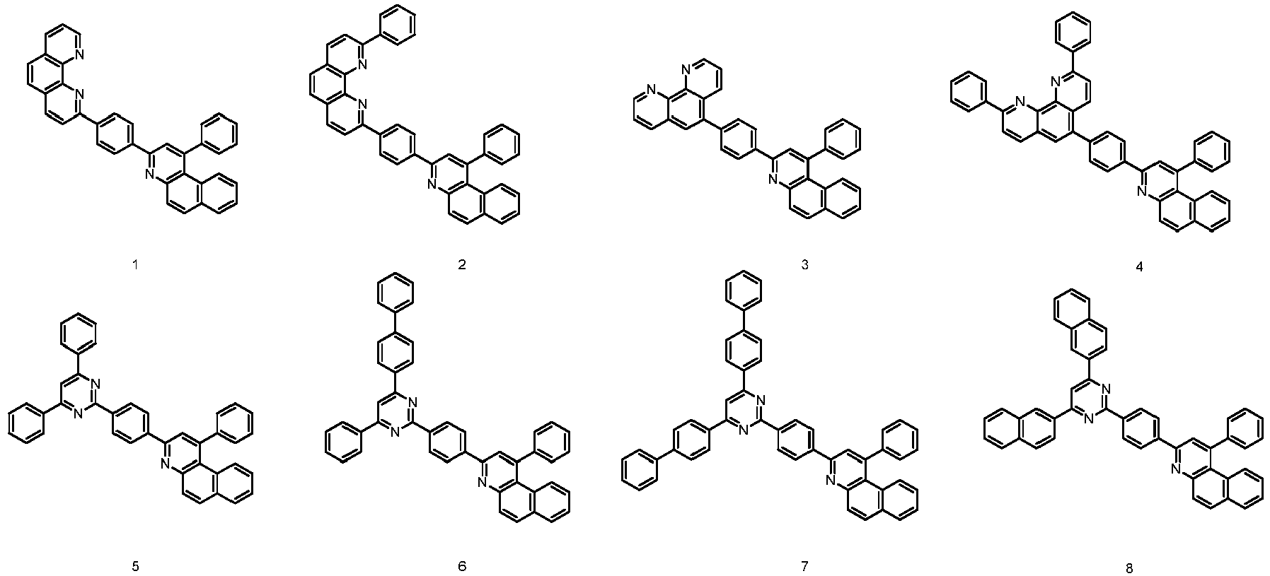
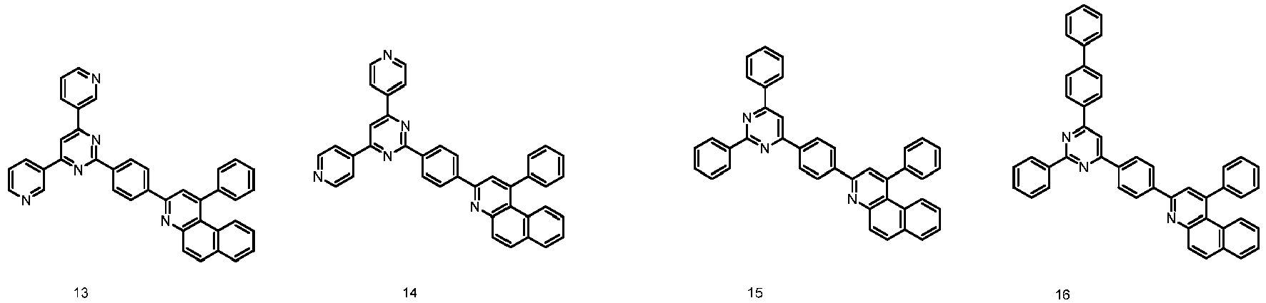
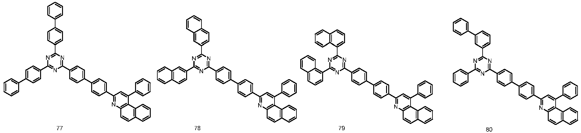
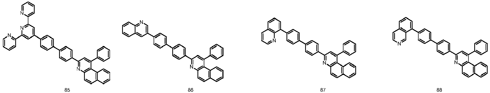
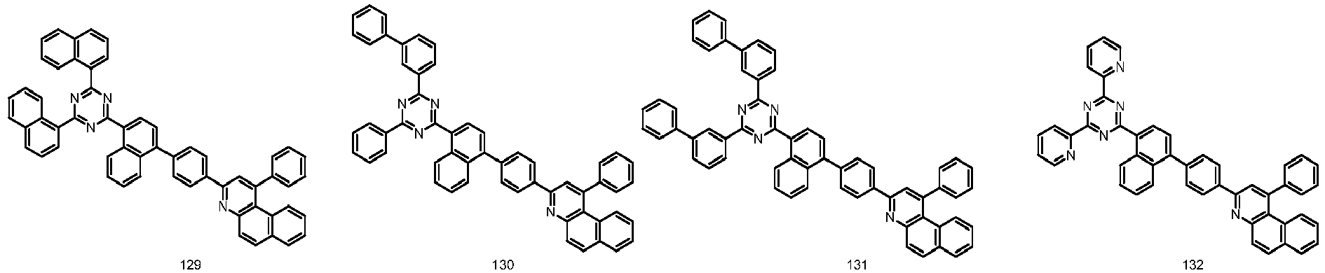
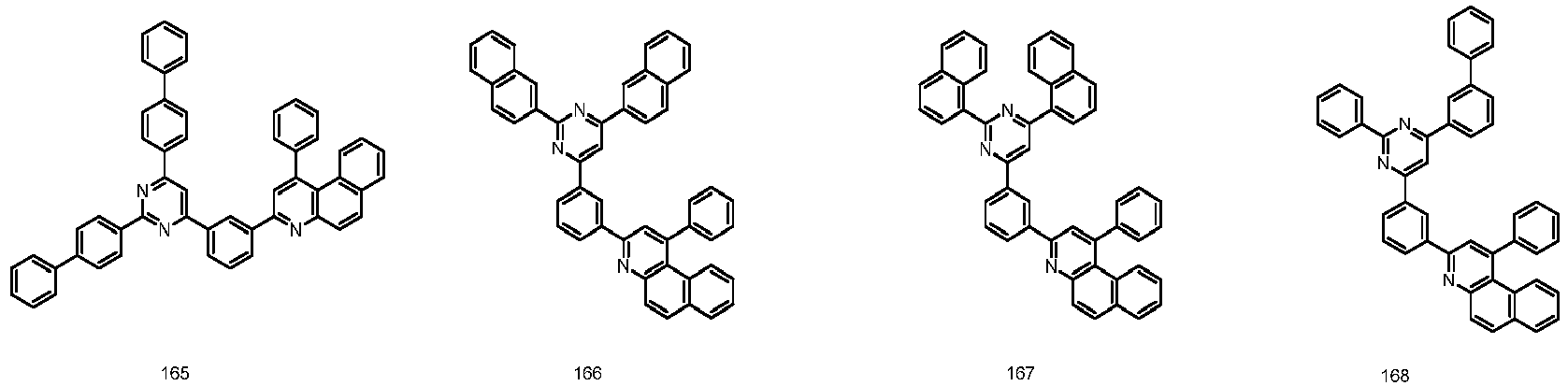
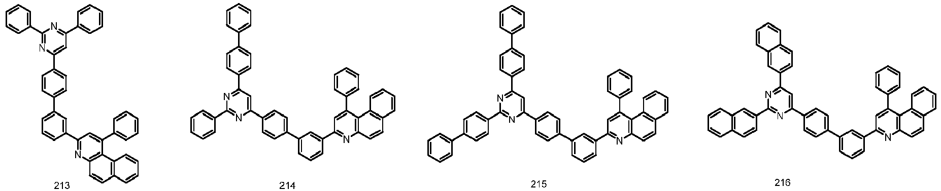
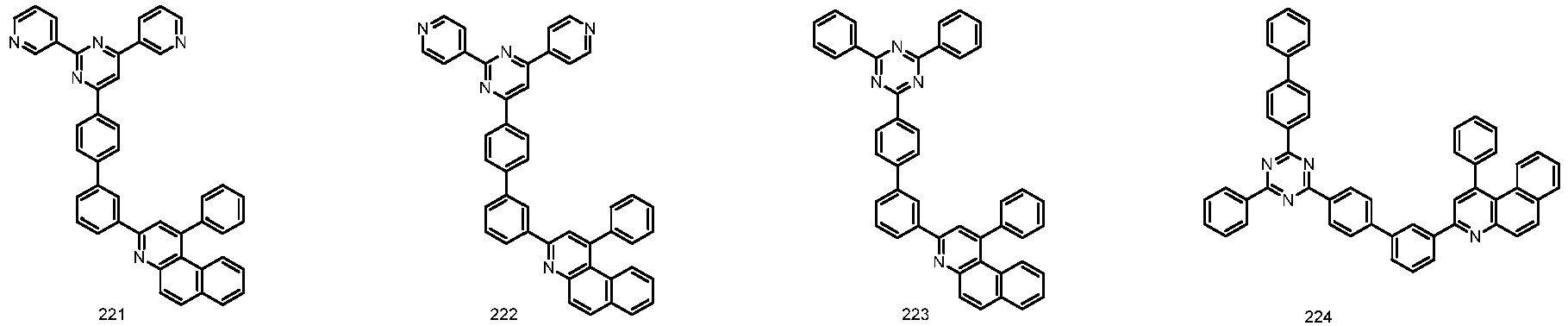
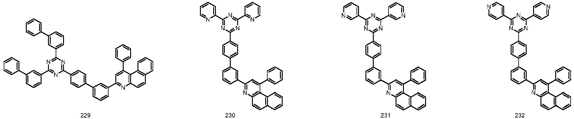
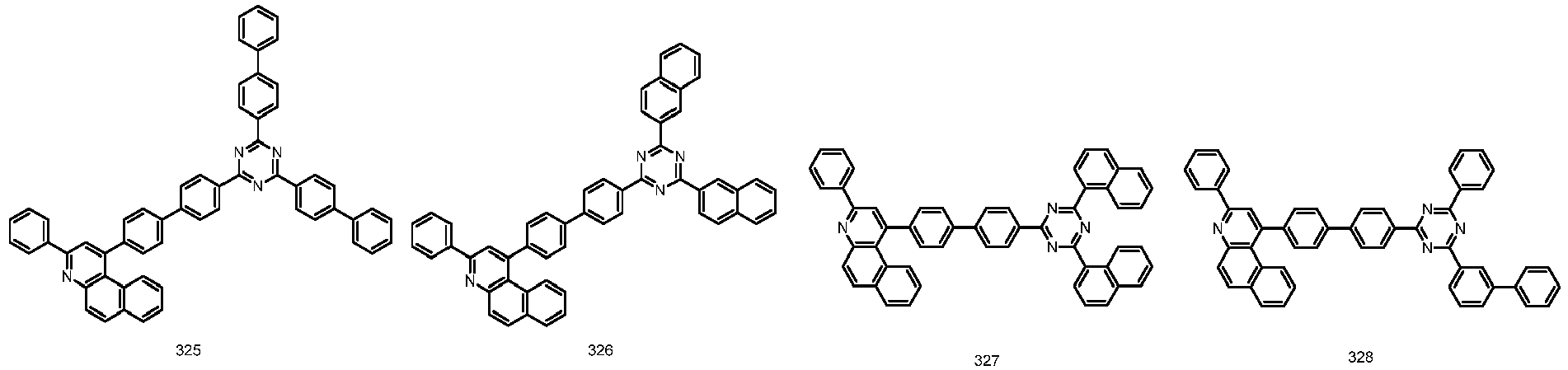
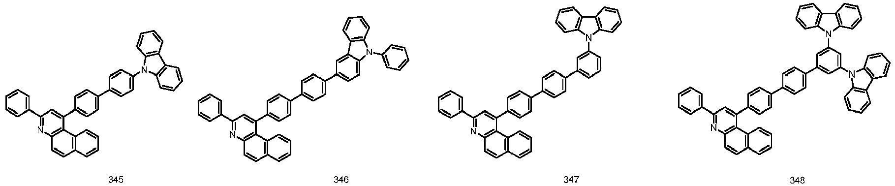
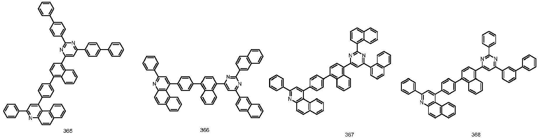
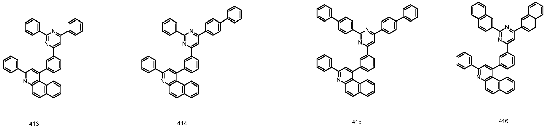
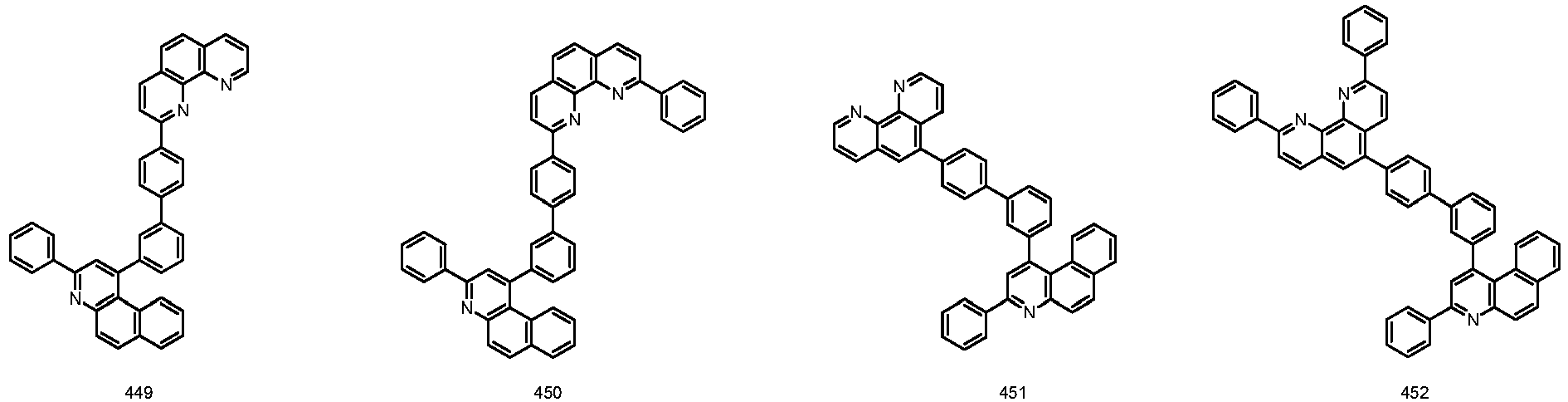
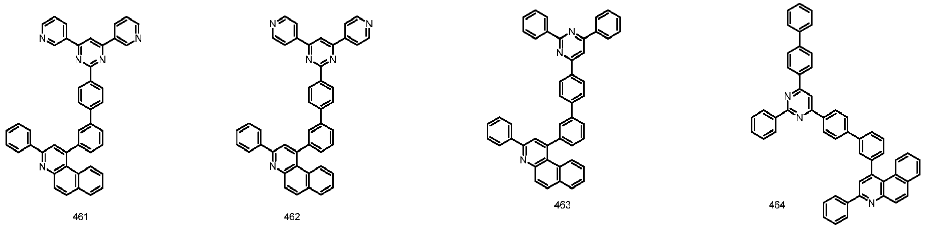
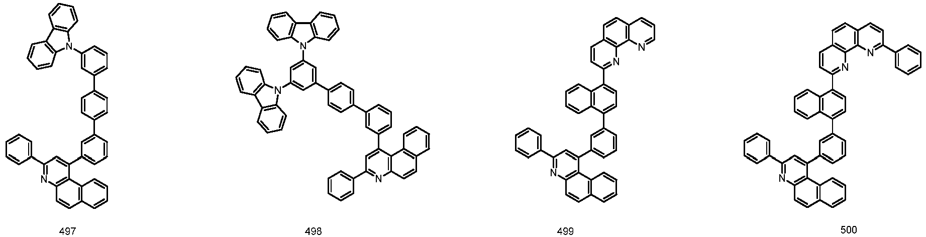
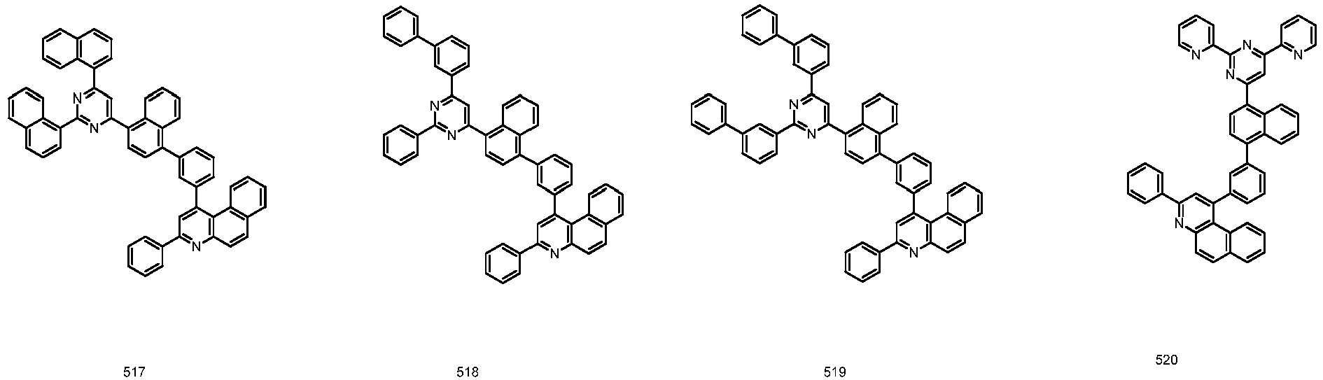
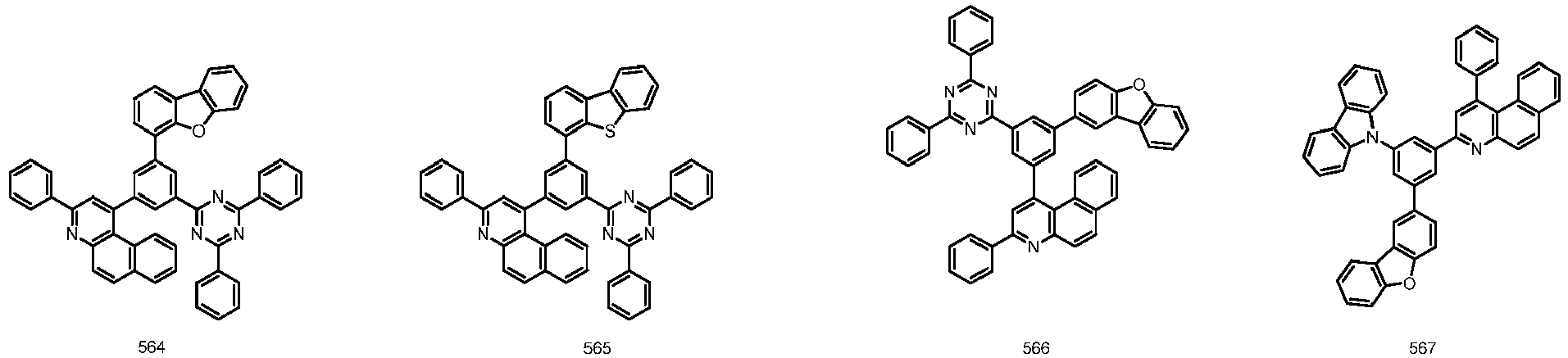
- Chemical Formula 2 or 3 may be represented by any one of the following compounds, but is not limited thereto.
- substituents to the structure of Chemical Formula 2 or 3
- compounds having unique properties of the introduced substituents may be synthesized.
- substituents normally used as hole injection layer materials, hole transfer layer materials, light emitting layer materials, electron transfer layer materials and charge generation layer materials used for manufacturing an organic light emitting device to the core structure, materials satisfying conditions required for each organic material layer may be synthesized.
- the energy band gap may be finely controlled, and meanwhile, properties at interfaces between organic materials are enhanced, and material applications may become diverse.
- the hetero-cyclic compound has excellent thermal stability with a high glass transition temperature (Tg). Such an increase in the thermal stability becomes an important factor in providing driving stability to a device.
- the hetero-cyclic compound according to one embodiment of the present application may be prepared through a multistep chemical reaction. Some intermediate compounds are prepared first, and the compound may be prepared from the intermediate compounds. More specifically, the hetero-cyclic compound according to one embodiment of the present application may be prepared based on preparation examples to be described below.
- Another embodiment of the present application provides an organic light emitting device comprising the hetero-cyclic compound represented by Chemical Formula 2 or 3.
- the organic light emitting device may be manufactured using common organic light emitting device manufacturing methods and materials except that one or more organic material layers are formed using the hetero-cyclic compound described above.
- the hetero-cyclic compound may be formed into an organic material layer through a solution coating method as well as a vacuum deposition method when manufacturing the organic light emitting device.
- the solution coating method means spin coating, dip coating, inkjet printing, screen printing, a spray method, roll coating and the like, but is not limited thereto.
- the organic light emitting device comprises an anode, a cathode, and one or more organic material layers provided between the anode and the cathode, wherein one or more layers of the organic material layers comprise the heterocyclic compound represented by Chemical Formula 2 or 3.
- FIGs. 1 to 3 illustrate a lamination order of electrodes and organic material layers of an organic light emitting device according to one embodiment of the present application.
- FIG. 1 illustrates an organic light emitting device in which an anode (200), an organic material layer (300) and a cathode (400) are consecutively laminated on a substrate (100).
- the structure is not limited to such a structure, and as illustrated in FIG. 2 , an organic light emitting device in which a cathode, an organic material layer and an anode are consecutively laminated on a substrate may also be obtained.
- FIG. 3 illustrates a case of the organic material layer being a multilayer.
- the organic light emitting device according to FIG. 3 comprises a hole injection layer (301), a hole transfer layer (302), a light emitting layer (303), a hole blocking layer (304), an electron transfer layer (305) and an electron injection layer (306).
- the organic light emitting device according to one embodiment of the present application comprises an anode, a cathode, and two or more stacks provided between the anode and the cathode, wherein the two or more stacks each independently comprise a light emitting layer, a charge generation layer is included between the two or more stacks, and the charge generation layer comprises the hetero-cyclic compound represented by Chemical Formula 2 or 3.
- the organic light emitting device comprises an anode, a first stack provided on the anode and comprising a first light emitting layer, a charge generation layer provided on the first stack, a second stack provided on the charge generation layer and comprising a second light emitting layer, and a cathode provided on the second stack.
- the charge generation layer may comprise the hetero-cyclic compound represented by Chemical Formula 2 or 3.
- the first stack and the second stack may each independently further comprise one or more types of the hole injection layer, the hole transfer layer, the hole blocking layer, the electron transfer layer, the electron injection layer described above and the like.
- the charge generation layer may be an N-type charge generation layer, and the charge generation layer may further comprise a dopant known in the art in addition to the heterocyclic compound represented by Chemical Formula 2 or 3.
- an organic light emitting device having a 2-stack tandem structure is schematically illustrated in FIG. 4 .
- the first electron blocking layer, the first bole blocking layer, the second hole blocking layer and the like described in FIG. 4 may not be included in some cases.
- the organic light emitting device according to the present specification may be manufactured using materials and methods known in the art except that one or more layers of the organic material layers comprise the hetero-cyclic compound represented by Chemical Formula 2 or 3.
- the hetero-cyclic compound represented by Chemical Formula 2 or 3 may form one or more layers of the organic material layers of the organic light emitting device alone. However, as necessary, the hetero-cyclic compound represented by Chemical Formula 2 or 3 may be mixed with other materials to form the organic material layers.
- the hetero-cyclic compound represented by Chemical Formula 2 or 3 may be used as a material of the charge generation layer in the organic light emitting device.
- the hetero-cyclic compound represented by Chemical Formula 2 or 3 may be used as a material of the electron transfer layer, the hole blocking layer, the light emitting layer or the like in the organic light emitting device.
- the hetero-cyclic compound represented by Chemical Formula 2 or 3 may be used as a material of the electron transfer layer, the hole transfer layer or the light emitting layer in the organic light emitting device.
- hetero-cyclic compound represented by Chemical Formula 2 or 3 may be used as a material of the light emitting layer in the organic light emitting device.
- the hetero-cyclic compound represented by Chemical Formula 2 or 3 may be used as a phosphorescent host material of the light emitting layer in the organic light emitting device.
- anode material materials having relatively large work function may be used, and transparent conductive oxides, metals, conductive polymers or the like may be used.
- the anode material comprise metals such as vanadium, chromium, copper, zinc and gold, or alloys thereof; metal oxides such as zinc oxide, indium oxide, indium tin oxide (ITO) and indium zinc oxide (IZO); combinations of metals and oxides such as ZnO:Al or SnO 2 :Sb; conductive polymers such as poly(3-methylcompound), poly[3,4-(ethylene-1,2-dioxy)compound] (PEDOT), polypyrrole and polyaniline, but are not limited thereto.
- the cathode material materials having relatively small work function may be used, and metals, metal oxides, conductive polymers or the like may be used.
- Specific examples of the cathode material comprise metals such as magnesium, calcium, sodium, potassium, titanium, indium, yttrium, lithium, gadolinium, aluminum, silver, tin and lead, or alloys thereof; multilayer structure materials such as LiF/Al or LiO 2 /Al, and the like, but are not limited thereto.
- hole injection material known hole injection materials may be used, and for example, phthalocyanine compounds such as copper phthalocyanine disclosed in US Patent No. 4,356,429 , or starburst-type amine derivatives such as tris(4-carbazoyl-9-ylphenyl)amine (TCTA), 4,4',4"-tri[phenyl(m-tolyl)amino]triphenylamine (m-MTDATA) or 1,3,5-tris[4-(3-methylphenylphenylamino)phenyl]benzene (m-MTDAPB) described in the literature [ Advanced Material, 6, p.677 (1994 )], polyaniline/dodecylbenzene sulfonic acid, poly(3,4-ethylenedioxythiophene)/poly(4-styrenesulfonate), polyaniline/camphor sulfonic acid or polyaniline/poly(4-styrene-sulfonate) that
- hole transfer material pyrazoline derivatives, arylamine-based derivatives, stilbene derivatives, triphenyldiamine derivatives and the like may be used, and low molecular or high molecular materials may also be used.
- LiF is typically used in the art, however, the present application is not limited thereto.
- red, green or blue light emitting materials may be used, and as necessary, two or more light emitting materials may be mixed and used.
- fluorescent materials may also be used as the light emitting material, however, phosphorescent materials may also be used.
- materials emitting light by bonding electrons and holes injected from an anode and a cathode, respectively, may be used alone, however, materials having a host material and a dopant material involved in light emission together may also be used.
- the organic light emitting device may be a top-emission type, a bottom-emission type or a dual-emission type depending on the materials used.
- the hetero-cyclic compound according to one embodiment of the present application may also be used in an organic electronic device comprising an organic solar cell, an organic photo conductor, an organic transistor and the like under a similar principle used in the organic light emitting device.
- Nitromethane (600 ml) was introduced to naphthalen-2-amine (60 g, 419.02 mmol, 1 eq.), 4-bromobenzaldehyde (77.5 g, 419.02 mmol, 1 eq.) and ethynylbenzene (64.2 g, 628.54 mmol, 1.5 eq.), iodine (10.6 g, 41.90 mmol, 0.1 eq.) was added thereto, and the result was stirred at 100°C.
- the result was silica-gel filtered, and precipitated using MC/MeOH and MC/acetone.
- Target Compound A was synthesized in the same manner using, in Preparation Example 1, Intermediate A of the following Table 1 instead of 2-bromo-1,10-phenanthroline. [Table 1] Compound Number Intermediate A Target Compound A Yield 2 65% 3 71% 5 69% 15 83% 25 78% 35 67% 45 70% 46 62% 50 84% 52 71% 102 74%
- Nitromethane (600 ml) was introduced to naphthalen-2-amine (60 g, 419.02 mmol, 1 eq.), 3-bromobenzaldehyde (77.5 g, 419.02 mmol, 1 eq.) and ethynylbenzene (64.2 g, 628.54 mmol, 1.5 eq.), iodine (10.6 g, 41.90 mmol, 0.1 eq.) was added thereto, and the result was stirred at 100°C.
- the result was silica-gel filtered, and precipitated using MC/MeOH and MC/acetone.
- Target Compound B was synthesized in the same manner using, in Preparation Example 2, Intermediate B of the following Table 2 instead of 2-bromo-1,10-phenanthroline. [Table 2] Compound Number Intermediate B Target Compound B Yield 150 69% 151 73% 153 64% 163 88% 173 72% 183 69% 194 69% 198 81% 199 73% 555 81%
- Tetrahydrofuran (375 mL) and distilled water (3.75 mL) were introduced to naphthalen-2-amine (15 g, 0.104 mol, 1 eq.), 4-bromoacetophenone (20.75 g, 0.104 mol, 1 eq.) and benzaldehyde (11.12 g, 0.104 mol, 1.5 eq.), iodine (1.3 g, 0.0052 mol, 0.05 eq.) was added thereto, and the result was stirred at 80°C.
- the result was silica-gel filtered, and precipitated using MC/MeOH and MC/acetone.
- Target Compound C was synthesized in the same manner using, in Preparation Example 3, Intermediate C of the following Table 3 instead of 2-bromo-1,10-phenanthroline. [Table 3] Compound Number Intermediate C Target Compound C Yield 344 65% 345 70% 556 72%
- Table 4 shows measurement values of 1 H NMR (CDCl 3 , 200 MHz), and Table 5 shows measurement values of field desorption mass spectrometry (FD-MS).
- a glass substrate on which ITO was coated as a thin film to a thickness of 1500 ⁇ was cleaned with distilled water and ultrasonic waves. After the cleaning with distilled water was finished, the substrate was ultrasonic cleaned with solvents such as acetone, methanol and isopropyl alcohol, then dried, and UVO treatment was carried out for 5 minutes in a UV cleaner using UV. After that, the substrate was transferred to a plasma cleaner (PT), and plasma treatment was carried out under vacuum for removing ITO work function and remaining film, and the substrate was transferred to a thermal deposition apparatus for organic deposition.
- PT plasma cleaner
- a hole transfer layer was formed first by thermal vacuum depositing TAPC to a thickness of 300 ⁇ . After forming the hole transfer layer, a light emitting layer was thermal vacuum deposited thereon as follows. The light emitting layer was deposited to 300 ⁇ by doping FIrpic in 8% as a blue phosphorescent dopant to TCz1, a host. An electron transfer layer was formed to 400 ⁇ using TmPyPB, and then a charge generation layer was formed to 100 ⁇ by doping CS 2 CO 3 in 20% to a compound described in the following Table 6.
- a hole injection layer was formed first by thermal vacuum depositing MoO 3 to a thickness of 50 ⁇ .
- a hole transfer layer a common layer, was formed by doping MoO 3 to TAPC in 20% and forming to 100 ⁇ , and then depositing TAPC to 300 ⁇ .
- an electron injection layer was formed on the electron transfer layer by depositing lithium fluoride (LiF) to a thickness of 10 ⁇ , and then a cathode was formed on the electron injection layer by depositing an aluminum (Al) cathode to a thickness of 1,200 ⁇ to manufacture an organic light emitting device.
- LiF lithium fluoride
- Al aluminum
- Example 85 450 7.68 54.10 (0.230, 0.424) 38
- Example 86 451 7.70 56.34 (0.233, 0.419) 38
- Example 87 453 7.75 56.38 (0.231, 0.420) 39
- Example 88 463 7.68 57.20 (0.233, 0.421) 35
- Example 89 7.73 7.71 57.11 (0.232, 0.422) 33
- Example 90 484 7.72 55.55 (0.232, 0.421)
- Example 91 4.92 7.76 55.40 (0.232, 0.422) 32
- Example 93 494 7.56 56.88 (0.231, 0.419) 35
- Example 94 495 7.60 56.80 (0.229, 0.423) 36
- Example 95 7.58 56.15 (0.228, 0.424)
- Example 96 498 7.49 56.87 (0.226, 0.434)
- the organic light emitting devices using the charge generation layer material of the 2-stack white organic light emitting device of the present disclosure had a low driving voltage and improved light emission efficiency compared to Comparative Example 1. Particularly, it was identified that Compounds 1, 2, 3, 35, 52, 102, 149, 150, 151, 183, 199 and 555 were significantly excellent in all of driving, efficiency and lifespan.
- the compound of the present disclosure used as an N-type charge generation layer formed with an invented skeleton having proper length, strength and flat property and a proper hetero-compound capable of binding with metals is doped with an alkali metal or an alkali-earth metal to form a gap state within the N-type charge generation layer, and electrons produced from a P-type charge generation layer are readily injected to the electron transfer layer through the gap state produced within the N-type charge generation layer.
- the P-type charge generation layer favorably carried out electron injection and electron transfer to the N-type charge generation layer, and as a result, it is considered that a driving voltage of the organic light emitting device decreased, and efficiency and lifespan were improved.
- a glass substrate on which ITO was coated as a thin film to a thickness of 1500 ⁇ was cleaned with distilled water and ultrasonic waves. After the cleaning with distilled water was finished, the substrate was ultrasonic cleaned with solvents such as acetone, methanol and isopropyl alcohol, then dried, and UVO treatment was carried out for 5 minutes in a UV cleaner using UV. After that, the substrate was transferred to a plasma cleaner (PT), and plasma treatment was carried out under vacuum for removing ITO work function and remaining film, and the substrate was transferred to a thermal deposition apparatus for organic deposition. On the ITO transparent electrode (anode), organic materials were formed in a single-stack structure.
- solvents such as acetone, methanol and isopropyl alcohol
- HAT-CN As a hole injection layer, HAT-CN was deposited to a thickness of 50 ⁇ , and subsequently, a hole transfer layer was formed by doping DNTPD within 10% to NPD, depositing the result to a thickness of 1500 ⁇ , and continuously depositing TCTA to a thickness of 200 ⁇ . Subsequently, a light emitting layer comprising a t-Bu-perylene dopant in an ADN host was formed to a thickness of 250 ⁇ .
- Alq 3 an electron transfer layer, was formed to a thickness of 250 ⁇ , and an N-type charge transfer layer was formed to a thickness of 100 ⁇ by doping Li, an alkali metal, to a compound described in the following Table 7, and Al, a cathode, was formed to a thickness of approximately 1,000 ⁇ to manufacture an organic light emitting device.
- the organic light emitting devices using the charge generation layer material of the blue organic light emitting device of the present disclosure had a low driving voltage and improved light emission efficiency compared to Comparative Example 2. Particularly, it was identified that Compounds 1, 2, 3, 35, 52, 102, 149, 150, 151, 183, 199 and 555 were significantly excellent in all of driving, efficiency and lifespan.
- the compound of the present disclosure used as an N-type charge generation layer formed with an invented skeleton having proper length, strength and flat property and a proper hetero-compound capable of binding with metals is doped with an alkali metal or an alkali-earth metal to form a gap state within the N-type charge generation layer, and electrons produced from a P-type charge generation layer are readily injected to the electron transfer layer through the gap state produced within the N-type charge generation layer.
- the P-type charge generation layer favorably carried out electron injection and electron transfer to the N-type charge generation layer, and as a result, it is considered that a driving voltage of the organic light emitting device decreased, and efficiency and lifespan were improved.
- a transparent electrode ITO thin film obtained from glass for an OLED (manufactured by Samsung Corning Advanced Glass) was ultrasonic cleaned consecutively using trichloroethylene, acetone, ethanol and distilled water for 5 minutes each, placed in isopropanol and stored, and then used.
- the ITO substrate was installed in a substrate folder of vacuum deposition equipment, and the following 4,4',4"-tris(N,N-(2-naphthyl)-phenylamino)triphenyl amine (2-TNATA) was introduced to a cell in the vacuum deposition equipment.
- the chamber was exhausted until the degree of vacuum inside the chamber reached 10 -6 torr, and then a current was applied to the cell to evaporate the 2-TNATA to deposit a hole injection layer having a thickness of 600 ⁇ on the ITO substrate.
- NPB N,N'-bis( ⁇ -naphthyl)-N,N'-diphenyl-4,4'-diamine
- a blue light emitting material having a structure as follows was deposited thereon as a light emitting layer. Specifically, H1, a blue light emitting host material, was vacuum deposited to a thickness of 200 ⁇ on one cell in the vacuum deposition equipment, and D1, a blue light emitting dopant material, was vacuum deposited thereon in 5% with respect to the host material.
- lithium fluoride LiF
- Al cathode As an electron injection layer, lithium fluoride (LiF) was deposited to a thickness of 10 ⁇ , and an Al cathode was formed to a thickness of 1,000 ⁇ to manufacture an OLED device.
- Example 201 1 5.48 6.02 (0.134, 0.102) 32
- Example 202 2 5.39 6.24 (0.134, 0.102) 31
- Example 203 3 5.35 6.34 (0.134, 0.100) 31
- Example 204 5 4.45 6.98 (0.134, 0.100) 40
- Example 205 15 4.50 6.99 (0.134, 0.101) 41
- Example 206 25 4.48 6.85 (0.134, 0.099) 40
- Example 207 35 5.38 5.64 (0.134, 0.100) 29
- Example 208 36 5.44 5.85 (0.134, 0.100) 33
- Example 209 44 5.38 5.90 (0.134, 0.100) 36
- Example 210 45 5.22 6.01 (0.134, 0.100) 28
- Example 211 46 4.70 6.67 (0.134, 0.102) 61
- Example 212 47 5.28 6.10 (0.134, 0.100) 40
- Example 213 48 5.30 6.20 (0.134, 0.101) 40
- Example 214 50 4.45 7.03
- the organic light emitting devices using the electron transfer layer material of the blue organic light emitting device of the present disclosure had a low driving voltage and significantly improved light emission efficiency and lifespan compared to Comparative Example 3. Particularly, it was identified that Compounds 5, 15, 25, 46, 50, 153, 163, 173, 194 and 198 were significantly excellent in all of driving, efficiency and lifespan.
Landscapes
- Chemical & Material Sciences (AREA)
- Organic Chemistry (AREA)
- Engineering & Computer Science (AREA)
- Materials Engineering (AREA)
- Physics & Mathematics (AREA)
- Spectroscopy & Molecular Physics (AREA)
- Optics & Photonics (AREA)
- Electroluminescent Light Sources (AREA)
- Nitrogen Condensed Heterocyclic Rings (AREA)
- Plural Heterocyclic Compounds (AREA)
Claims (8)
- Heterocyclische Verbindung, die durch die folgende chemische Formel 2 oder 3 dargestellt ist:

 wenigstens eines von R1 bis R5 durch (L2)p-(Z2)q dargestellt ist und der Rest Wasserstoff sind,wenigstens eines von R12 bis R16 durch -(L3)r-(Z3)s dargestellt ist und der Rest Wasserstoff sind,L2 und L3 gleich oder verschieden voneinander sind und jeweils unabhängig eine direkte Bindung; oder eine substituierte oder unsubstituierte C6- bis C60-Arylengruppe sind,Z2 und Z3 gleich oder verschieden voneinander sind und jeweils unabhängig ausgewählt sind aus der Gruppe bestehend aus einer substituierten oder unsubstituierten Pyridingruppe; einer substituierten oder unsubstituierten Pyrimidingruppe; einer substituierten oder unsubstituierten Triazingruppe; einer substituierten oder unsubstituierten Phenanthrolingruppe; einer substituierten oder unsubstituierten Chinolingruppe; einer substituierten oder unsubstituierten Carbazolgruppe; einer substituierten oder unsubstituierten Dibenzofurangruppe; einer substituierten oder unsubstituierten Dibenzothiophengruppe; einer substituierten oder unsubstituierten Anthracengruppe; einer substituierten oder unsubstituierten Phenanthrengruppe; einer substituierten oder unsubstituierten Biphenylgruppe; einer substituierten oder unsubstituierten Naphthylgruppe; und -P(=O)RR',p und r eine ganze Zahl von 0 bis 4 sind;q und s eine ganze Zahl von 1 bis 4 sind;R6 bis R11 Wasserstoff sind, undR und R' gleich oder verschieden voneinander sind und jeweils unabhängig eine substituierte oder unsubstituierten C6- bis C60-Arylgruppe sind.
 - Heterocyclische Verbindung nach Anspruch 1, wobei chemische Formel 2 oder 3 durch eine der folgenden Verbindungen dargestellt ist:


- Organische lichtemittierende Vorrichtung, umfassend:eine Anode;eine Kathode; undeine oder mehrere organische Materialschichten, die zwischen der Anode und der Kathode bereitgestellt ist bzw. sind,wobei eine oder mehrere Schichten der organischen Materialschichten die heterocyclische Verbindung nach einem der Ansprüche 1 und 2 umfasst.
- Organische lichtemittierende Vorrichtung nach Anspruch 3, wobei die organische Materialschicht wenigstens eine einer Lochblockierschicht, einer Elektroneninjektionsschicht und einer Elektronentransferschicht umfasst, wobei wenigstens eine der Lochblockierschicht, der Elektroneninjektionsschicht und der Elektronentransferschicht die heterocyclische Verbindung umfasst.
- Organische lichtemittierende Vorrichtung nach Anspruch 3, wobei die organische Materialschicht eine lichtemittierende Schicht umfasst, und wobei die lichtemittierende Schicht die heterocyclische Verbindung umfasst.
- Organische lichtemittierende Vorrichtung nach Anspruch 3, wobei die organische Materialschicht eine oder mehrere einer Lochinjektionsschicht, einer Lochtransferschicht und einer Schicht, die gleichzeitig Lochinjektion und Lochtransfer durchführt, umfasst, und wobei eine der oben erwähnten Schichten die heterocyclische Verbindung umfasst.
- Organische lichtemittierende Vorrichtung nach Anspruch 3, wobei die organische Materialschicht eine Ladungserzeugungsschicht umfasst, und wobei die Ladungserzeugungsschicht die heterocyclische Verbindung umfasst.
- Organische lichtemittierende Vorrichtung nach Anspruch 3, umfassend:eine Anode;einen ersten Stapel, der auf der Anode bereitgestellt ist und eine erste lichtemittierende Schicht umfasst;eine Ladungserzeugungsschicht, die auf dem ersten Stapel bereitgestellt ist;einen zweiten Stapel, der auf der Ladungserzeugungsschicht bereitgestellt ist und eine zweite lichtemittierende Schicht umfassend: undeine Kathode, die auf dem zweiten Stapel bereitgestellt ist.
Applications Claiming Priority (2)
| Application Number | Priority Date | Filing Date | Title |
|---|---|---|---|
| KR1020160085748A KR101838693B1 (ko) | 2016-07-06 | 2016-07-06 | 헤테로고리 화합물 및 이를 이용한 유기 발광 소자 |
| PCT/KR2017/007250 WO2018009007A1 (ko) | 2016-07-06 | 2017-07-06 | 헤테로고리 화합물 및 이를 이용한 유기 발광 소자 |
Publications (3)
| Publication Number | Publication Date |
|---|---|
| EP3483146A1 EP3483146A1 (de) | 2019-05-15 |
| EP3483146A4 EP3483146A4 (de) | 2019-12-25 |
| EP3483146B1 true EP3483146B1 (de) | 2021-10-20 |
Family
ID=60913065
Family Applications (1)
| Application Number | Title | Priority Date | Filing Date |
|---|---|---|---|
| EP17824563.5A Active EP3483146B1 (de) | 2016-07-06 | 2017-07-06 | Heterocyclische verbindung und organische lichtemittierende vorrichtung damit |
Country Status (7)
| Country | Link |
|---|---|
| US (1) | US11239427B2 (de) |
| EP (1) | EP3483146B1 (de) |
| JP (1) | JP7029820B2 (de) |
| KR (1) | KR101838693B1 (de) |
| CN (1) | CN109476607B (de) |
| TW (1) | TWI735613B (de) |
| WO (1) | WO2018009007A1 (de) |
Families Citing this family (8)
| Publication number | Priority date | Publication date | Assignee | Title |
|---|---|---|---|---|
| KR102308643B1 (ko) * | 2017-12-29 | 2021-10-05 | 삼성에스디아이 주식회사 | 유기 화합물, 조성물, 유기 광전자 소자 및 표시 장치 |
| JP7773788B2 (ja) * | 2019-12-02 | 2025-11-20 | エルティー・マテリアルズ・カンパニー・リミテッド | ヘテロ環化合物およびこれを含む有機発光素子 |
| KR20220067040A (ko) | 2020-11-17 | 2022-05-24 | 엘티소재주식회사 | 헤테로 고리 화합물, 이를 포함하는 유기발광소자, 및 유기물층 형성용 조성물 |
| KR102721995B1 (ko) | 2020-12-21 | 2024-10-25 | 엘티소재주식회사 | 헤테로 고리 화합물 및 이를 포함하는 유기발광소자 |
| KR102949076B1 (ko) * | 2021-12-31 | 2026-04-08 | 엘지디스플레이 주식회사 | 발광 소자 및 이를 이용한 발광 표시 장치 |
| US20230217821A1 (en) * | 2021-12-31 | 2023-07-06 | Lg Display Co., Ltd. | Light Emitting Device and Light Emitting Display Device Including the Same |
| CN115974843B (zh) * | 2023-02-15 | 2026-03-03 | 电子科技大学 | 基于氮杂环的激基复合物受体材料及其制备方法和应用 |
| KR20260036795A (ko) * | 2024-09-09 | 2026-03-17 | 엘티소재주식회사 | 헤테로고리 화합물 및 이를 포함하는 유기 발광 소자 |
Family Cites Families (16)
| Publication number | Priority date | Publication date | Assignee | Title |
|---|---|---|---|---|
| US4356429A (en) | 1980-07-17 | 1982-10-26 | Eastman Kodak Company | Organic electroluminescent cell |
| KR101148460B1 (ko) | 2004-08-23 | 2012-05-23 | 도레이 카부시키가이샤 | 발광 소자용 재료 및 발광 소자 |
| CN101077971B (zh) | 2006-05-25 | 2010-08-11 | 清华大学 | 一种有机电致磷光发光材料及其应用 |
| JP2008177459A (ja) | 2007-01-22 | 2008-07-31 | Sony Corp | 有機電界発光素子および表示装置 |
| JP2008243932A (ja) | 2007-03-26 | 2008-10-09 | Sony Corp | 有機電界発光素子および表示装置 |
| JP2010280512A (ja) * | 2007-09-25 | 2010-12-16 | Osaka Univ | 無機有機複合物質、無機有機複合物質の製造方法、無機有機複合物質を用いた製品 |
| KR20100047466A (ko) * | 2008-10-29 | 2010-05-10 | 다우어드밴스드디스플레이머티리얼 유한회사 | 신규한 전자재료용 화합물 및 이를 포함하는 유기 전자 소자 |
| KR101432600B1 (ko) | 2010-12-31 | 2014-08-21 | 제일모직주식회사 | 유기광전소자용 화합물 및 이를 포함하는 유기광전소자 |
| US9309223B2 (en) * | 2011-07-08 | 2016-04-12 | Semiconductor Energy Laboratory Co., Ltd. | Heterocyclic compound, light-emitting element, light-emitting device, electronic device, and lighting device |
| US9299942B2 (en) | 2012-03-30 | 2016-03-29 | Semiconductor Energy Laboratory Co., Ltd. | Light-emitting element, light-emitting device, display device, electronic appliance, and lighting device |
| CN104812750A (zh) | 2012-10-04 | 2015-07-29 | 罗门哈斯电子材料韩国有限公司 | 有机电致发光化合物和包含其的有机电致发光装置 |
| GB2517931B (en) | 2013-09-04 | 2017-11-08 | Kelvin Hughes Ltd | Radar apparatus for a ship |
| KR101645200B1 (ko) | 2014-03-04 | 2016-08-03 | 한국교통대학교산학협력단 | 벤조퀴놀린 유도체 및 이를 채용한 유기전계발광소자 |
| KR102195540B1 (ko) * | 2014-04-25 | 2020-12-29 | 덕산네오룩스 주식회사 | 유기전기 소자용 화합물, 이를 이용한 유기전기소자 및 그 전자 장치 |
| US11107994B2 (en) | 2014-06-18 | 2021-08-31 | Merck Patent Gmbh | Materials for organic electroluminescent devices |
| KR102230925B1 (ko) | 2014-07-14 | 2021-03-24 | 엘지디스플레이 주식회사 | 유기발광소자 |
-
2016
- 2016-07-06 KR KR1020160085748A patent/KR101838693B1/ko active Active
-
2017
- 2017-07-06 JP JP2019500236A patent/JP7029820B2/ja active Active
- 2017-07-06 EP EP17824563.5A patent/EP3483146B1/de active Active
- 2017-07-06 TW TW106122754A patent/TWI735613B/zh active
- 2017-07-06 WO PCT/KR2017/007250 patent/WO2018009007A1/ko not_active Ceased
- 2017-07-06 US US16/315,485 patent/US11239427B2/en active Active
- 2017-07-06 CN CN201780041958.7A patent/CN109476607B/zh active Active
Non-Patent Citations (1)
| Title |
|---|
| ZHOU QIANHAO ET AL: "Altering the Position of Phenyl Substitution to Adjust Film Morphology and Memory Device Performance", CHEMISTRY - AN ASIAN JOURNAL, vol. 10, no. 7, 12 May 2015 (2015-05-12), pages 1474 - 1479, XP055786690, ISSN: 1861-4728, DOI: 10.1002/asia.201500062 * |
Also Published As
| Publication number | Publication date |
|---|---|
| TW201821590A (zh) | 2018-06-16 |
| TWI735613B (zh) | 2021-08-11 |
| CN109476607B (zh) | 2022-11-08 |
| JP7029820B2 (ja) | 2022-03-04 |
| EP3483146A4 (de) | 2019-12-25 |
| EP3483146A1 (de) | 2019-05-15 |
| US11239427B2 (en) | 2022-02-01 |
| US20190319195A1 (en) | 2019-10-17 |
| JP2019523244A (ja) | 2019-08-22 |
| CN109476607A (zh) | 2019-03-15 |
| KR20180005534A (ko) | 2018-01-16 |
| KR101838693B1 (ko) | 2018-03-14 |
| WO2018009007A1 (ko) | 2018-01-11 |
Similar Documents
| Publication | Publication Date | Title |
|---|---|---|
| EP3604297B1 (de) | Heterocyclische verbindung und organisches lichtemittierendes element damit | |
| EP3604298B1 (de) | Heterocyclische verbindung und organisches lichtemittierendes element damit | |
| EP4190779A1 (de) | Heterocyclische verbindung, organische lichtemittierende vorrichtung damit und zusammensetzung für organische schicht einer organischen lichtemittierenden vorrichtung | |
| EP3757095A2 (de) | Heterocyclische verbindung und organische lichtemittierende vorrichtung mit verwendung davon | |
| EP3483146B1 (de) | Heterocyclische verbindung und organische lichtemittierende vorrichtung damit | |
| US11427562B2 (en) | Heterocyclic compound, and organic light-emitting device using same | |
| KR102523619B1 (ko) | 헤테로고리 화합물 및 이를 이용한 유기 발광 소자 | |
| KR101882221B1 (ko) | 헤테로고리 화합물 및 이를 이용한 유기 발광 소자 | |
| EP3243820B1 (de) | Heterocyclische verbindung und organische leuchtdiode damit | |
| EP4015515A1 (de) | Heterocyclische verbindung und organische lichtemittierende vorrichtung damit | |
| EP3689869A1 (de) | Heterocyclische verbindung und organische lichtemittierende vorrichtung damit | |
| KR102626318B1 (ko) | 화합물 및 이를 이용한 유기 발광 소자 | |
| US11133477B2 (en) | Heterocyclic compound and organic light emitting element using same | |
| KR20210072414A (ko) | 헤테로고리 화합물 및 이를 포함하는 유기 발광 소자 | |
| US11665961B2 (en) | Heterocyclic compound and organic light emitting device using same | |
| EP3858831A1 (de) | Heterocyclische verbindung und organische leuchtdiode damit | |
| KR102177590B1 (ko) | 헤테로고리 화합물 및 이를 이용한 유기 발광 소자 | |
| JP7773796B2 (ja) | ヘテロ環化合物およびそれを含む有機発光素子 | |
| KR20210017039A (ko) | 헤테로고리 화합물 및 이를 포함하는 유기 발광 소자 |
Legal Events
| Date | Code | Title | Description |
|---|---|---|---|
| STAA | Information on the status of an ep patent application or granted ep patent |
Free format text: STATUS: THE INTERNATIONAL PUBLICATION HAS BEEN MADE |
|
| PUAI | Public reference made under article 153(3) epc to a published international application that has entered the european phase |
Free format text: ORIGINAL CODE: 0009012 |
|
| STAA | Information on the status of an ep patent application or granted ep patent |
Free format text: STATUS: REQUEST FOR EXAMINATION WAS MADE |
|
| 17P | Request for examination filed |
Effective date: 20181219 |
|
| AK | Designated contracting states |
Kind code of ref document: A1 Designated state(s): AL AT BE BG CH CY CZ DE DK EE ES FI FR GB GR HR HU IE IS IT LI LT LU LV MC MK MT NL NO PL PT RO RS SE SI SK SM TR |
|
| AX | Request for extension of the european patent |
Extension state: BA ME |
|
| DAV | Request for validation of the european patent (deleted) | ||
| DAX | Request for extension of the european patent (deleted) | ||
| A4 | Supplementary search report drawn up and despatched |
Effective date: 20191125 |
|
| RIC1 | Information provided on ipc code assigned before grant |
Ipc: H01L 51/00 20060101ALI20191119BHEP Ipc: C07D 403/10 20060101ALI20191119BHEP Ipc: C07D 221/06 20060101AFI20191119BHEP Ipc: C09K 11/06 20060101ALI20191119BHEP Ipc: C07D 471/04 20060101ALI20191119BHEP Ipc: H01L 51/50 20060101ALI20191119BHEP Ipc: C07D 401/10 20060101ALI20191119BHEP |
|
| RAP1 | Party data changed (applicant data changed or rights of an application transferred) |
Owner name: LT MATERIALS CO., LTD. |
|
| STAA | Information on the status of an ep patent application or granted ep patent |
Free format text: STATUS: EXAMINATION IS IN PROGRESS |
|
| 17Q | First examination report despatched |
Effective date: 20210324 |
|
| GRAP | Despatch of communication of intention to grant a patent |
Free format text: ORIGINAL CODE: EPIDOSNIGR1 |
|
| STAA | Information on the status of an ep patent application or granted ep patent |
Free format text: STATUS: GRANT OF PATENT IS INTENDED |
|
| INTG | Intention to grant announced |
Effective date: 20210730 |
|
| GRAS | Grant fee paid |
Free format text: ORIGINAL CODE: EPIDOSNIGR3 |
|
| GRAA | (expected) grant |
Free format text: ORIGINAL CODE: 0009210 |
|
| STAA | Information on the status of an ep patent application or granted ep patent |
Free format text: STATUS: THE PATENT HAS BEEN GRANTED |
|
| AK | Designated contracting states |
Kind code of ref document: B1 Designated state(s): AL AT BE BG CH CY CZ DE DK EE ES FI FR GB GR HR HU IE IS IT LI LT LU LV MC MK MT NL NO PL PT RO RS SE SI SK SM TR |
|
| REG | Reference to a national code |
Ref country code: GB Ref legal event code: FG4D |
|
| REG | Reference to a national code |
Ref country code: CH Ref legal event code: EP |
|
| REG | Reference to a national code |
Ref country code: IE Ref legal event code: FG4D |
|
| REG | Reference to a national code |
Ref country code: DE Ref legal event code: R096 Ref document number: 602017048003 Country of ref document: DE |
|
| REG | Reference to a national code |
Ref country code: AT Ref legal event code: REF Ref document number: 1439842 Country of ref document: AT Kind code of ref document: T Effective date: 20211115 |
|
| REG | Reference to a national code |
Ref country code: LT Ref legal event code: MG9D |
|
| REG | Reference to a national code |
Ref country code: NL Ref legal event code: MP Effective date: 20211020 |
|
| REG | Reference to a national code |
Ref country code: AT Ref legal event code: MK05 Ref document number: 1439842 Country of ref document: AT Kind code of ref document: T Effective date: 20211020 |
|
| PG25 | Lapsed in a contracting state [announced via postgrant information from national office to epo] |
Ref country code: RS Free format text: LAPSE BECAUSE OF FAILURE TO SUBMIT A TRANSLATION OF THE DESCRIPTION OR TO PAY THE FEE WITHIN THE PRESCRIBED TIME-LIMIT Effective date: 20211020 Ref country code: LT Free format text: LAPSE BECAUSE OF FAILURE TO SUBMIT A TRANSLATION OF THE DESCRIPTION OR TO PAY THE FEE WITHIN THE PRESCRIBED TIME-LIMIT Effective date: 20211020 Ref country code: FI Free format text: LAPSE BECAUSE OF FAILURE TO SUBMIT A TRANSLATION OF THE DESCRIPTION OR TO PAY THE FEE WITHIN THE PRESCRIBED TIME-LIMIT Effective date: 20211020 Ref country code: BG Free format text: LAPSE BECAUSE OF FAILURE TO SUBMIT A TRANSLATION OF THE DESCRIPTION OR TO PAY THE FEE WITHIN THE PRESCRIBED TIME-LIMIT Effective date: 20220120 Ref country code: AT Free format text: LAPSE BECAUSE OF FAILURE TO SUBMIT A TRANSLATION OF THE DESCRIPTION OR TO PAY THE FEE WITHIN THE PRESCRIBED TIME-LIMIT Effective date: 20211020 |
|
| PG25 | Lapsed in a contracting state [announced via postgrant information from national office to epo] |
Ref country code: IS Free format text: LAPSE BECAUSE OF FAILURE TO SUBMIT A TRANSLATION OF THE DESCRIPTION OR TO PAY THE FEE WITHIN THE PRESCRIBED TIME-LIMIT Effective date: 20220220 Ref country code: SE Free format text: LAPSE BECAUSE OF FAILURE TO SUBMIT A TRANSLATION OF THE DESCRIPTION OR TO PAY THE FEE WITHIN THE PRESCRIBED TIME-LIMIT Effective date: 20211020 Ref country code: PT Free format text: LAPSE BECAUSE OF FAILURE TO SUBMIT A TRANSLATION OF THE DESCRIPTION OR TO PAY THE FEE WITHIN THE PRESCRIBED TIME-LIMIT Effective date: 20220221 Ref country code: PL Free format text: LAPSE BECAUSE OF FAILURE TO SUBMIT A TRANSLATION OF THE DESCRIPTION OR TO PAY THE FEE WITHIN THE PRESCRIBED TIME-LIMIT Effective date: 20211020 Ref country code: NO Free format text: LAPSE BECAUSE OF FAILURE TO SUBMIT A TRANSLATION OF THE DESCRIPTION OR TO PAY THE FEE WITHIN THE PRESCRIBED TIME-LIMIT Effective date: 20220120 Ref country code: NL Free format text: LAPSE BECAUSE OF FAILURE TO SUBMIT A TRANSLATION OF THE DESCRIPTION OR TO PAY THE FEE WITHIN THE PRESCRIBED TIME-LIMIT Effective date: 20211020 Ref country code: LV Free format text: LAPSE BECAUSE OF FAILURE TO SUBMIT A TRANSLATION OF THE DESCRIPTION OR TO PAY THE FEE WITHIN THE PRESCRIBED TIME-LIMIT Effective date: 20211020 Ref country code: HR Free format text: LAPSE BECAUSE OF FAILURE TO SUBMIT A TRANSLATION OF THE DESCRIPTION OR TO PAY THE FEE WITHIN THE PRESCRIBED TIME-LIMIT Effective date: 20211020 Ref country code: GR Free format text: LAPSE BECAUSE OF FAILURE TO SUBMIT A TRANSLATION OF THE DESCRIPTION OR TO PAY THE FEE WITHIN THE PRESCRIBED TIME-LIMIT Effective date: 20220121 Ref country code: ES Free format text: LAPSE BECAUSE OF FAILURE TO SUBMIT A TRANSLATION OF THE DESCRIPTION OR TO PAY THE FEE WITHIN THE PRESCRIBED TIME-LIMIT Effective date: 20211020 |
|
| REG | Reference to a national code |
Ref country code: DE Ref legal event code: R097 Ref document number: 602017048003 Country of ref document: DE |
|
| PG25 | Lapsed in a contracting state [announced via postgrant information from national office to epo] |
Ref country code: SM Free format text: LAPSE BECAUSE OF FAILURE TO SUBMIT A TRANSLATION OF THE DESCRIPTION OR TO PAY THE FEE WITHIN THE PRESCRIBED TIME-LIMIT Effective date: 20211020 Ref country code: SK Free format text: LAPSE BECAUSE OF FAILURE TO SUBMIT A TRANSLATION OF THE DESCRIPTION OR TO PAY THE FEE WITHIN THE PRESCRIBED TIME-LIMIT Effective date: 20211020 Ref country code: RO Free format text: LAPSE BECAUSE OF FAILURE TO SUBMIT A TRANSLATION OF THE DESCRIPTION OR TO PAY THE FEE WITHIN THE PRESCRIBED TIME-LIMIT Effective date: 20211020 Ref country code: EE Free format text: LAPSE BECAUSE OF FAILURE TO SUBMIT A TRANSLATION OF THE DESCRIPTION OR TO PAY THE FEE WITHIN THE PRESCRIBED TIME-LIMIT Effective date: 20211020 Ref country code: DK Free format text: LAPSE BECAUSE OF FAILURE TO SUBMIT A TRANSLATION OF THE DESCRIPTION OR TO PAY THE FEE WITHIN THE PRESCRIBED TIME-LIMIT Effective date: 20211020 Ref country code: CZ Free format text: LAPSE BECAUSE OF FAILURE TO SUBMIT A TRANSLATION OF THE DESCRIPTION OR TO PAY THE FEE WITHIN THE PRESCRIBED TIME-LIMIT Effective date: 20211020 |
|
| PLBE | No opposition filed within time limit |
Free format text: ORIGINAL CODE: 0009261 |
|
| STAA | Information on the status of an ep patent application or granted ep patent |
Free format text: STATUS: NO OPPOSITION FILED WITHIN TIME LIMIT |
|
| 26N | No opposition filed |
Effective date: 20220721 |
|
| PG25 | Lapsed in a contracting state [announced via postgrant information from national office to epo] |
Ref country code: AL Free format text: LAPSE BECAUSE OF FAILURE TO SUBMIT A TRANSLATION OF THE DESCRIPTION OR TO PAY THE FEE WITHIN THE PRESCRIBED TIME-LIMIT Effective date: 20211020 |
|
| PG25 | Lapsed in a contracting state [announced via postgrant information from national office to epo] |
Ref country code: SI Free format text: LAPSE BECAUSE OF FAILURE TO SUBMIT A TRANSLATION OF THE DESCRIPTION OR TO PAY THE FEE WITHIN THE PRESCRIBED TIME-LIMIT Effective date: 20211020 |
|
| PG25 | Lapsed in a contracting state [announced via postgrant information from national office to epo] |
Ref country code: MC Free format text: LAPSE BECAUSE OF FAILURE TO SUBMIT A TRANSLATION OF THE DESCRIPTION OR TO PAY THE FEE WITHIN THE PRESCRIBED TIME-LIMIT Effective date: 20211020 |
|
| REG | Reference to a national code |
Ref country code: CH Ref legal event code: PL |
|
| GBPC | Gb: european patent ceased through non-payment of renewal fee |
Effective date: 20220706 |
|
| REG | Reference to a national code |
Ref country code: BE Ref legal event code: MM Effective date: 20220731 |
|
| PG25 | Lapsed in a contracting state [announced via postgrant information from national office to epo] |
Ref country code: LU Free format text: LAPSE BECAUSE OF NON-PAYMENT OF DUE FEES Effective date: 20220706 Ref country code: CH Free format text: LAPSE BECAUSE OF NON-PAYMENT OF DUE FEES Effective date: 20220731 Ref country code: LI Free format text: LAPSE BECAUSE OF NON-PAYMENT OF DUE FEES Effective date: 20220731 |
|
| PG25 | Lapsed in a contracting state [announced via postgrant information from national office to epo] |
Ref country code: IT Free format text: LAPSE BECAUSE OF FAILURE TO SUBMIT A TRANSLATION OF THE DESCRIPTION OR TO PAY THE FEE WITHIN THE PRESCRIBED TIME-LIMIT Effective date: 20211020 Ref country code: GB Free format text: LAPSE BECAUSE OF NON-PAYMENT OF DUE FEES Effective date: 20220706 Ref country code: BE Free format text: LAPSE BECAUSE OF NON-PAYMENT OF DUE FEES Effective date: 20220731 |
|
| P01 | Opt-out of the competence of the unified patent court (upc) registered |
Effective date: 20230530 |
|
| PG25 | Lapsed in a contracting state [announced via postgrant information from national office to epo] |
Ref country code: IE Free format text: LAPSE BECAUSE OF NON-PAYMENT OF DUE FEES Effective date: 20220706 |
|
| PG25 | Lapsed in a contracting state [announced via postgrant information from national office to epo] |
Ref country code: HU Free format text: LAPSE BECAUSE OF FAILURE TO SUBMIT A TRANSLATION OF THE DESCRIPTION OR TO PAY THE FEE WITHIN THE PRESCRIBED TIME-LIMIT; INVALID AB INITIO Effective date: 20170706 |
|
| PG25 | Lapsed in a contracting state [announced via postgrant information from national office to epo] |
Ref country code: MK Free format text: LAPSE BECAUSE OF FAILURE TO SUBMIT A TRANSLATION OF THE DESCRIPTION OR TO PAY THE FEE WITHIN THE PRESCRIBED TIME-LIMIT Effective date: 20211020 Ref country code: CY Free format text: LAPSE BECAUSE OF FAILURE TO SUBMIT A TRANSLATION OF THE DESCRIPTION OR TO PAY THE FEE WITHIN THE PRESCRIBED TIME-LIMIT Effective date: 20211020 |
|
| PG25 | Lapsed in a contracting state [announced via postgrant information from national office to epo] |
Ref country code: MT Free format text: LAPSE BECAUSE OF FAILURE TO SUBMIT A TRANSLATION OF THE DESCRIPTION OR TO PAY THE FEE WITHIN THE PRESCRIBED TIME-LIMIT Effective date: 20211020 |
|
| PGFP | Annual fee paid to national office [announced via postgrant information from national office to epo] |
Ref country code: FR Payment date: 20250610 Year of fee payment: 9 |
|
| PGFP | Annual fee paid to national office [announced via postgrant information from national office to epo] |
Ref country code: DE Payment date: 20250604 Year of fee payment: 9 |
|
| PG25 | Lapsed in a contracting state [announced via postgrant information from national office to epo] |
Ref country code: TR Free format text: LAPSE BECAUSE OF FAILURE TO SUBMIT A TRANSLATION OF THE DESCRIPTION OR TO PAY THE FEE WITHIN THE PRESCRIBED TIME-LIMIT Effective date: 20211020 |