EP3483368A1 - Kraftfahrzeugschloss - Google Patents
Kraftfahrzeugschloss Download PDFInfo
- Publication number
- EP3483368A1 EP3483368A1 EP18205306.6A EP18205306A EP3483368A1 EP 3483368 A1 EP3483368 A1 EP 3483368A1 EP 18205306 A EP18205306 A EP 18205306A EP 3483368 A1 EP3483368 A1 EP 3483368A1
- Authority
- EP
- European Patent Office
- Prior art keywords
- crash
- actuating lever
- crash element
- motor vehicle
- vehicle lock
- Prior art date
- Legal status (The legal status is an assumption and is not a legal conclusion. Google has not performed a legal analysis and makes no representation as to the accuracy of the status listed.)
- Withdrawn
Links
- 230000007246 mechanism Effects 0.000 claims description 23
- 230000008878 coupling Effects 0.000 claims description 9
- 238000010168 coupling process Methods 0.000 claims description 9
- 238000005859 coupling reaction Methods 0.000 claims description 9
- 230000000694 effects Effects 0.000 claims description 7
- 230000001133 acceleration Effects 0.000 description 9
- 230000007704 transition Effects 0.000 description 9
- 230000003466 anti-cipated effect Effects 0.000 description 1
- 230000000903 blocking effect Effects 0.000 description 1
- 230000001419 dependent effect Effects 0.000 description 1
- 230000009977 dual effect Effects 0.000 description 1
- 238000000034 method Methods 0.000 description 1
- 230000008569 process Effects 0.000 description 1
- 230000009467 reduction Effects 0.000 description 1
- 230000000717 retained effect Effects 0.000 description 1
- 238000000926 separation method Methods 0.000 description 1
- 238000004804 winding Methods 0.000 description 1
Images



Classifications
-
- E—FIXED CONSTRUCTIONS
- E05—LOCKS; KEYS; WINDOW OR DOOR FITTINGS; SAFES
- E05B—LOCKS; ACCESSORIES THEREFOR; HANDCUFFS
- E05B77/00—Vehicle locks characterised by special functions or purposes
- E05B77/02—Vehicle locks characterised by special functions or purposes for accident situations
- E05B77/04—Preventing unwanted lock actuation, e.g. unlatching, at the moment of collision
- E05B77/06—Preventing unwanted lock actuation, e.g. unlatching, at the moment of collision by means of inertial forces
-
- E—FIXED CONSTRUCTIONS
- E05—LOCKS; KEYS; WINDOW OR DOOR FITTINGS; SAFES
- E05B—LOCKS; ACCESSORIES THEREFOR; HANDCUFFS
- E05B77/00—Vehicle locks characterised by special functions or purposes
- E05B77/02—Vehicle locks characterised by special functions or purposes for accident situations
- E05B77/04—Preventing unwanted lock actuation, e.g. unlatching, at the moment of collision
-
- Y—GENERAL TAGGING OF NEW TECHNOLOGICAL DEVELOPMENTS; GENERAL TAGGING OF CROSS-SECTIONAL TECHNOLOGIES SPANNING OVER SEVERAL SECTIONS OF THE IPC; TECHNICAL SUBJECTS COVERED BY FORMER USPC CROSS-REFERENCE ART COLLECTIONS [XRACs] AND DIGESTS
- Y10—TECHNICAL SUBJECTS COVERED BY FORMER USPC
- Y10S—TECHNICAL SUBJECTS COVERED BY FORMER USPC CROSS-REFERENCE ART COLLECTIONS [XRACs] AND DIGESTS
- Y10S292/00—Closure fasteners
- Y10S292/22—Inertia operated
Definitions
- the invention relates to a motor vehicle lock as claimed in the preamble of claim 1.
- motor vehicle lock all types of locks for a door, hood or tailgate are encompassed by the term "motor vehicle lock”.
- the crash safety of the motor vehicle lock in question is of particular importance.
- Such an inadvertent opening of the motor vehicle lock may be caused, for example, by the crash accelerations causing an automatic disengagement of a door handle.
- the known motor vehicle lock ( EP 2 339 098 A2 ), on which the invention is based, shows in one variant a mechanism for avoiding the inadvertent opening of the motor vehicle lock as a result of a crash.
- a crash element is provided, said crash element being latched in a crash position when an actuating lever is actuated at excessive actuating speed, as is to be anticipated in the event of a crash. In this crash position, the crash element blocks the actuating lever coupled to the door handle so that an inadvertent opening of the motor vehicle lock as a result of a crash is eliminated.
- the latching of the crash element in the crash position is advantageous insofar that crash accelerations often occur as a result of a plurality of individual accelerations which are different in terms of direction and intensity. Thus it may arise that two crash accelerations directly follow one another.
- crash mechanism provides a challenge to the person skilled in the art with regard to costs, compactness and operating safety, in particular when it is considered that in the crash state the latching has to be released again after the crash in the most uncomplicated manner possible.
- the problem underlying the invention is to simplify the known motor vehicle lock with regard to the crash mechanism, with a high level of operating reliability, a high level of compactness and with low costs.
- the adjustability of the crash element in the two adjusting directions may be implemented in a manner which is cost-effective and which at the same time is operationally reliable by using a simple mechanism, in particular a cam-cam follower mechanism to be described below.
- a crash actuation is such an actuation of the actuating lever which is caused by crash accelerations occurring in the event of a crash. Such crash accelerations are often more than 20 g.
- a normal actuation is such an actuation of the actuating lever which is caused by a manual actuating movement by an operator.
- the crash element is coupled to the actuating lever such that, with an actuation of the actuating lever depending on the actuating lever speed, the crash element reaches the released position from a central position either in a first adjusting direction or said crash element reaches the crash position in a second adjusting direction and is latched in the crash position.
- the crash element in the crash position blocks the actuating lever either in a blocked position or decouples said actuating lever from the locking pawl.
- the limit speed does not form a sharply defined boundary between a rapid actuation and a slow actuation of the actuating lever. Instead, this information is intended to clarify that a relatively slow actuation, which corresponds to normal actuation, leads to an adjustment of the crash element into the released position and that a relatively rapid actuation, which corresponds to the crash actuation, leads to an adjustment of the crash element into the crash position.
- Claim 4 also refers to a particularly user-friendly disengagement of the latching of the crash element.
- the return of the actuating lever into the initial position already effects the disengagement of the latching.
- the disengagement of the latching could hardly be implemented in a more intuitive manner.
- control mechanism is a cam-cam follower mechanism with a control cam and a cam follower running in the control cam, wherein the control cam and the cam follower in each case are assigned to one of the components, namely the actuating lever and the crash element.
- control cam may be designed as a simple recess in one of the two components, whilst the cam follower may be implemented simply as a curved portion, a riveted-on pin or the like.
- the control cam may be designed to be closed or open. It may also be formed from a plurality of cam portions which are optionally not connected together.
- the particularly preferred embodiments as claimed in claims 12 to 16 relate to details of the control cam.
- the adjustment of the crash element from the central position into the crash position is caused by a forced guidance between the control cam and the cam follower, in this case between the crash-cam portion and the cam follower.
- This is advantageous since during this adjustment of the crash element the crash element also has to be latched in the crash position which in principle requires a certain amount of force expenditure, which is able to be easily transmitted to the crash element via this forced guidance.
- Fig. 1 shows that the motor vehicle lock 1 has a lock housing 1a and locking elements therein, namely a latch 2 and locking pawl 3, which are operatively connected together in the conventional manner.
- the latch 2 is pivotable into the main locked position, shown in fig. 1 , in which it is held by the locking pawl 3.
- the latch 2 is in retained engagement with a locking part 4 which is designed in this case and preferably as a locking bolt.
- the locking pawl 3 may be pivoted about a locking pawl axis 3a, clockwise in fig. 1 , so that the latch 2 is released and may pivot about a latch axis 2a in fig. 1 counterclockwise in the opening direction. Then the locking part 4 is released and the motor vehicle door or the like, assigned to the motor vehicle lock 1, may be opened.
- the proposed motor vehicle lock 1 comprises at least one actuating lever 5 which is pivotable about an actuating lever axis 5a, by the actuation thereof said locking pawl 3 being disengageable from an initial position into an actuating position.
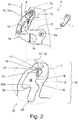
- the initial position is shown in fig. 2 .
- the actuation of the actuating lever 5 in the normal case results from the sequence of figs. 2 , 3a and 3b .
- the ability to disengage the locking pawl 3 depends, according to the embodiment of the motor vehicle lock 1, not only on the actuation of the actuating lever 5 but also on the locked state of a lock mechanism which is possibly provided but not shown here. This, however, is not significant for the proposed solution.
- the actuating lever 5 is coupled in this case and preferably to a door handle 6, in particular an external door handle.
- the door handle 6 may also be an internal door handle or any other door handle.
- the drive train to the door handle 6 is indicated by the reference numeral A, whilst the drive train to the locking pawl 3 is indicated by the reference numeral B.
- the drive train B is shown in dashed lines, due to the possibly provided lock mechanism.
- the motor vehicle lock 1 is provided with a crash element 7 which in a manner to be described below is adjustable into a released position, which is shown in fig. 3b and in which the locking pawl 3 is disengageable by an actuation of the actuating lever 5, and into a crash position shown in fig. 4b in which the crash element 7 blocks the actuating lever 5 in a blocked position.
- a crash element 7 which in a manner to be described below is adjustable into a released position, which is shown in fig. 3b and in which the locking pawl 3 is disengageable by an actuation of the actuating lever 5, and into a crash position shown in fig. 4b in which the crash element 7 blocks the actuating lever 5 in a blocked position.
- the actuating lever 5 is decoupled from the locking pawl 3, as will also be described below.
- the crash element 7 is coupled to the actuating lever 5 such that, with an actuation of the actuating lever 5 and depending on the actuating lever speed, the crash element 7 reaches the released position ( fig. 3b )) from a central position ( fig. 2 ) either in a first adjusting direction 8 or said crash element reaches the crash position in a second adjusting direction 9 and is latched in the crash position ( fig. 4b )).
- the speed-dependent adjustment of the crash element 7 is caused by the inertial forces which act on the crash element 7.
- the crash element 7 follows its pretensioning, also to be explained below.
- the inertial force acting on the crash element 7 ensures that the crash element 7 is not able to follow its pretensioning rapidly enough and is guided by the actuating lever 5 into the crash position.
- the term "latched" here means that the crash element 7 initially remains in the crash state, even if the actuation of the actuating lever 5 ceases in the case of excessive actuating speed. Only when the latching is released is the crash element 7 able to fall again into the central position.
- a comparison of fig. 2 with fig. 3b ) and a comparison of fig. 2 with fig. 4b ) shows that the first adjusting direction 8 of the crash element 7 and the second adjusting direction 9 of the crash element 7 are opposed to one another.
- the crash element 7 is pivotable about a crash element axis 7a, wherein the crash element 7 reaches the central position, the released position and the crash position by a pivoting of the crash element 7 about the crash element axis 7a.
- the pivotable embodiment of the crash element 7 results in an arrangement which is simple to implement and which is mechanically robust.
- the crash element 7 reaches the released position ( fig. 3b )) from the central position ( fig. 2 ) and with an actuation of the actuating lever 5 at an actuating lever speed which is above the limit speed, the crash element 7 reaches the crash position ( fig. 4b )) from the central position ( fig. 2 ) and is latched in the crash position.
- the actuating lever axis 5a is preferably fixedly arranged in the motor vehicle lock 1, i.e. fixed to the housing.
- the crash element axis 7a is also fixedly arranged in the motor vehicle lock 1, i.e. fixed to the housing.
- the crash element axis 7a is preferably also arranged remotely from the actuating lever axis 5a.
- the crash element 7 is mounted on the actuating lever 5.
- Other arrangements of the actuating lever 5 and crash element 7, which correspondingly require other coupling mechanisms between these two components, are conceivable.
- a crash element spring 11 is provided, said crash element spring in this case and preferably pretensioning the crash element 7 into the released position, in fig. 2 counterclockwise.
- the crash element spring 11 is designed as a wire spring, in this case and preferably as a leg spring.
- the crash element spring 11 for producing the pretensioning of the crash element 7 into its released position is supported on the lock housing 1a, on the one hand, and on the crash element 7, on the other hand.
- the actuating lever 5 is pretensioned by an actuating lever spring 10 in the direction of the initial position, counterclockwise in fig. 2 .
- a particularly advantageous variant for implementing the latching of the crash element 7 in its crash position may also be derived from the view according to fig. 2 .
- a latching arrangement 12 is provided with a latching spring 13 which latches the crash element 7 during its adjustment into the crash position.
- the process of the latching of the crash element 7 results from the transition from fig. 4a) to fig. 4b ).
- the latching spring 13 forms a latching lug 14, during the transition from fig. 4a) to fig. 4b ) the crash element 7 being latched over said latching lug, such that the crash element 7 is secured in a latched manner in the crash position shown in fig. 4b ).
- the latching of the crash element 7 is released, in this case and preferably by an overlatching of the latching spring 13 on this occasion in the opposing direction.
- Other types of latching are conceivable.
- a particularly compact embodiment results from the latching spring 13 being provided by the crash element spring 11.
- the crash element spring 11 in this regard has a dual function.
- the latching spring 13 is designed integrally with the crash element spring 11.
- the latching spring 13 is bent back from a leg of the crash element spring 11 designed as a leg spring.
- the latching spring 13 and the crash element spring 11 are configured integrally as discussed above.
- the latching spring 13 may be provided by a leg of the crash element spring 11 itself, designed as a leg spring. Then the latching lug 14 of the latching spring 13 is preferably configured in an end region of the relevant leg of the crash element spring 11.
- the crash element 7 is designed as a lever which is pivotable about a crash element axis 7a, a cam follower 17 being arranged on the lever arm thereof, to be explained further below, it may be advantageous that the winding axis of the crash element spring 11 which is designed as a leg spring is aligned with the crash element axis 7a and that a leg is in non-positive engagement with the cam follower (not shown).
- this leg at the end side has the latching lug 14 of the latching spring 13, which is further preferably supported on the cam follower 17.
- the leg spring is stabilized by the crash element 7 which permits a design which is particularly insensitive to tolerances.
- the crash element spring 11 is continuously in non-positive engagement with the crash element 7, the provision of the latching spring 13 by the crash element spring 11 is also particularly advantageous in this regard relative to potential production tolerances.
- crash element spring 11 is designed integrally with the latching spring 13 result in lower material and mounting costs and, due to a reduction in mechanical interfaces, are in turn particularly insensitive to tolerances.
- this coupling comprises a control mechanism 15 for the movement control of the crash element 7, said control mechanism guiding the crash element 7, as also indicated above, when the actuating lever 5 is actuated at an actuating lever speed below the limit speed, into the released position and guiding the crash element 7, at an actuating lever speed above the limit speed, into the crash position.
- the function of releasing the latching of the crash element 7 is assigned to the control mechanism 15.
- the control mechanism 15 effects the release of the latching and the adjustment of the crash element 7 into the central position.
- the crash element 7 when the crash element 7 is latched in the crash position and only when the actuating lever 5 is returned by at least 80 per cent relative to the movement range between the initial position and the actuating position, in this case and preferably only when the actuating lever 5 is fully returned into the initial position, this causes the release of the latching and the adjustment of the crash element 7 into the central position.
- control mechanism 15 comprises a control cam 16 and a cam follower 17 operatively connected to the control cam 16, and which in each case are assigned to one of the components, namely the actuating lever 5 and crash element 7.
- control cam 16 is assigned to the actuating lever 5 and the cam follower 17 is assigned to the crash element 7.
- control cam 16 comprises a start-cam portion 18, the cam follower 17 being supported thereon by the pretensioning of the crash element spring 11, when the actuating lever 5 is in the initial position, and said start-cam portion determining the central position of the crash element 7.
- a release-cam portion 19 adjoins the start-cam portion 18, the cam follower 17 sliding along said release-cam portion when the actuating lever 5 is actuated at an actuating lever speed below the limit speed, whereby the crash element 7, driven by the pretensioning of the crash element spring 11, is guided from the central position into the released position.
- the cam follower 17 enters a cam channel 22. This appears from the transition from fig. 2 to fig. 3a ) and to fig. 3b ).
- the control cam 16 is provided with a crash-cam portion 20.
- the cam follower 17 comes into engagement with the crash-cam portion 20 and slides along said crash-cam portion. This appears in the transition from fig. 2 to fig. 4a ) and to fig. 4b .
- the transition from fig. 4a) to fig. 4b ) shows that by the cam follower 17 sliding along the crash-cam portion 20, the crash element 7 is guided from the central position into the crash position, in this case and preferably counter to the pretensioning of the crash element spring 11, and is latched there by the latching arrangement 12. From the view according to fig. 4b ) it may be derived that the crash element 7 in the crash position blocks a further actuation of the actuating element 5 in the blocked position via the engagement between the cam follower 17 and the crash-cam portion 18.
- the cam follower 17 initially slides along the start-cam portion 18.
- the cam follower is pretensioned by the crash element spring 11 on the start-cam portion 18 and with a further actuation of the actuating lever 5 would, in principle, be driven by the pretensioning of the crash element spring 11 sliding along the release-cam portion 19, so that the crash element 7 would reach the released position.
- the actuation of the actuating lever 5 is carried out at such a high actuating lever speed that the crash-cam portion 20 with its capture portion 20a comes into engagement with the cam follower 17 before the crash element 7 is able to pivot substantially in the direction of its released position.
- the crash-cam portion 20 guides the cam follower 17 and thus the crash element 7 in fig. 4b ) to the left so that the crash element 7 reaches the crash position and is correspondingly latched there by the latching arrangement 12, in particular by the overlatching of the latching spring 13.
- control cam 16 comprises a reset-cam portion 21, wherein, when the crash element 7 is latched in the crash position and when the actuating lever 5 has returned from the blocked position into the initial position, the cam follower 17 comes into engagement with the reset-cam portion 21 and slides along said portion, whereby the crash element 7 is guided from the crash position into the central position, releasing the latching, This appears from the transition from fig. 4b) to fig. 4c ) and to fig. 2 .
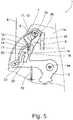
- Fig. 5 shows an alternative embodiment of the proposed motor vehicle lock 1, in which the crash element 7 located in the crash position does not block the actuating lever 5 but is decoupled from the locking pawl 5.
- the cam follower 17 comes into engagement with the crash-cam portion 20, so that the crash element 7, as explained in connection with the first exemplary embodiment, is adjusted from the central position in the second adjusting direction 9 into the crash position.
- the crash-cam portion 20 here does not provide a blocking surface. Instead the crash-cam portion 20 guides the cam follower 17 into the cam channel 23 so that the actuating lever 5 is able to reach its actuating position.
- the exemplary embodiment shown in fig. 5 namely comprises a coupling lever 24 of a coupling, not shown, which in the actuated state effects an interruption of the drive train B between the actuating lever 5 and the locking pawl 3.
- the crash element 7 is provided with a cam lobe 25 which, during the adjustment of the crash element 7 from the central position into the crash position, is brought into engagement with the coupling lever 24 and triggers an actuation of the coupling, which is associated with the above interruption of the drive train B between the actuating lever 5 and the locking pawl 3.
Landscapes
- Lock And Its Accessories (AREA)
Applications Claiming Priority (1)
| Application Number | Priority Date | Filing Date | Title |
|---|---|---|---|
| US15/809,434 US11078689B2 (en) | 2017-11-10 | 2017-11-10 | Motor vehicle lock |
Publications (1)
| Publication Number | Publication Date |
|---|---|
| EP3483368A1 true EP3483368A1 (de) | 2019-05-15 |
Family
ID=64270652
Family Applications (1)
| Application Number | Title | Priority Date | Filing Date |
|---|---|---|---|
| EP18205306.6A Withdrawn EP3483368A1 (de) | 2017-11-10 | 2018-11-09 | Kraftfahrzeugschloss |
Country Status (2)
| Country | Link |
|---|---|
| US (1) | US11078689B2 (de) |
| EP (1) | EP3483368A1 (de) |
Families Citing this family (3)
| Publication number | Priority date | Publication date | Assignee | Title |
|---|---|---|---|---|
| EP3034723B1 (de) * | 2014-12-18 | 2017-06-21 | U-Shin France | Schloss für einen Öffnungsflügel eines Kraftfahrzeugs |
| US10801236B2 (en) | 2017-12-01 | 2020-10-13 | Brose Schilesssysteme GmbH & Co. Kommanditgesellschaft | Hatch arrangement of a motor vehicle |
| DE102022113045A1 (de) * | 2022-05-24 | 2023-11-30 | Kiekert Aktiengesellschaft | Kraftfahrzeug-Schloss |
Citations (4)
| Publication number | Priority date | Publication date | Assignee | Title |
|---|---|---|---|---|
| DE29622837U1 (de) * | 1996-06-20 | 1997-07-24 | Kiekert AG, 42579 Heiligenhaus | Kraftfahrzeugtürverschluß mit Drehfalle, Sperrklinke und einer Blockiervorrichtung |
| EP2339098A2 (de) | 2009-12-26 | 2011-06-29 | Brose Schliesssysteme GmbH & Co. KG | Kraftfahrzeugschlossanordnung |
| US20140284939A1 (en) * | 2013-03-25 | 2014-09-25 | Brose Schliesssysteme Gmbh & Co. Kg | Motor vehicle lock |
| EP3121354A1 (de) * | 2015-07-20 | 2017-01-25 | U-Shin Italia S.p.A. | Sicherheitsvorrichtung für einen fahrzeugtürgriff |
Family Cites Families (53)
| Publication number | Priority date | Publication date | Assignee | Title |
|---|---|---|---|---|
| JPS5811275A (ja) * | 1981-07-08 | 1983-01-22 | 日産自動車株式会社 | 自動車の緊急ドアロツク解錠装置 |
| US4806712A (en) | 1988-03-02 | 1989-02-21 | General Motors Corporation | Electrical switch for door latch |
| DE19511651C5 (de) * | 1994-04-15 | 2008-07-10 | Volkswagen Ag | Sicherung für eine Fahrzeugtür gegen ungewolltes Öffnen beim Auftreten stoßbedingter seitlicher Massenträgheitskräfte |
| US5639130A (en) | 1995-05-31 | 1997-06-17 | General Motors Corporation | Rotary door cinching mechanism with manual override |
| DE19624640C1 (de) * | 1996-06-20 | 1998-01-08 | Kiekert Ag | Kraftfahrzeugtürverschluß mit Drehfalle, Sperrklinke und Blockiervorrichtung |
| DE19736445B4 (de) | 1996-08-22 | 2006-06-08 | Asmo Co., Ltd., Kosai-shi | Türgliedverriegelungs-/entriegelungsvorrichtung |
| DE19738492A1 (de) * | 1996-09-07 | 1998-03-12 | Volkswagen Ag | Kraftfahrzeugtürverschluß |
| GB2328242B (en) | 1997-05-23 | 2001-05-16 | Rockwell Lvs | Vehicle door latch |
| US6125583A (en) | 1997-08-13 | 2000-10-03 | Atoma International Inc. | Power sliding mini-van door |
| US6053542A (en) | 1998-06-26 | 2000-04-25 | General Motors Corporation | Vehicle door latch with cinching mechanism |
| DE19841309C2 (de) | 1998-09-10 | 2001-10-18 | Huf Huelsbeck & Fuerst Gmbh | Schloß für Klappen, Türen oder dgl. von Fahrzeugen, insbesondere Handschuhfach-Schloß |
| US6256932B1 (en) | 1999-06-29 | 2001-07-10 | Daimlerchrysler Corporation | Electronically-controlled vehicle door system |
| US6123372A (en) | 1999-07-21 | 2000-09-26 | Delphi Technologies, Inc. | Door latch |
| DE19942360C2 (de) | 1999-09-04 | 2003-11-13 | Kiekert Ag | Kraftfahrzeugtürverschluß |
| US6435600B1 (en) | 1999-12-21 | 2002-08-20 | Daimlerchrysler Corporation | Method for operating a vehicle power sliding door |
| JP3754285B2 (ja) | 2000-09-27 | 2006-03-08 | 株式会社大井製作所 | ドアの自動開閉装置 |
| US6719356B2 (en) | 2001-04-26 | 2004-04-13 | Litens Automotive | Powered opening mechanism and control system |
| US6679531B2 (en) | 2001-05-03 | 2004-01-20 | Delphi Technologies, Inc. | Vehicle compartment latch |
| DE10133092A1 (de) | 2001-07-11 | 2003-01-30 | Huf Huelsbeck & Fuerst Gmbh | Schloß, insbesondere für Kraftfahrzeugtüren, -klappen od. dgl. |
| US7093887B2 (en) | 2001-11-29 | 2006-08-22 | Intier Automotive Closures Inc. | Drive assembly for a power closure panel |
| WO2003062575A1 (en) | 2002-01-24 | 2003-07-31 | Intier Automotive Closures Inc. | Power lift gate actuator |
| US8056944B2 (en) * | 2002-06-13 | 2011-11-15 | Ford Global Technologies | Latch assembly for a vehicle door |
| CA2401397A1 (en) * | 2002-07-26 | 2004-01-26 | Intier Automotive Closures Inc. | Inertia catch for a vehicle latch |
| US20040124662A1 (en) | 2002-09-27 | 2004-07-01 | Cleland Terry P. | Low-mounted powered opening system and control mechanism |
| US6854781B2 (en) | 2003-04-23 | 2005-02-15 | Arvinmeritor Technology Llc | Vehicle tailgate dampener and lift assist system |
| US20060181108A1 (en) | 2003-09-29 | 2006-08-17 | Cleland Terry P | Low-mounted powered opening system and control mechanism |
| US7540551B2 (en) | 2003-11-20 | 2009-06-02 | Intier Automotive Closures, Inc. | System for power closing of a self rising closure panel |
| DE202005008151U1 (de) | 2005-03-10 | 2006-07-27 | Brose Schließsysteme GmbH & Co.KG | Antriebsanordnung für verstellbare Funktionselemente in einem Kraftfahrzeug |
| DE102005061610A1 (de) | 2005-12-21 | 2007-07-05 | Brose Fahrzeugteile Gmbh & Co. Kommanditgesellschaft, Coburg | Verfahren und Vorrichtung zum Steuern der Schließbewegung eines Karosseriebauteils für Fahrzeuge |
| JP2008057157A (ja) | 2006-08-30 | 2008-03-13 | Aisin Seiki Co Ltd | 移動体の制御装置 |
| JP5317255B2 (ja) | 2006-11-06 | 2013-10-16 | アイシン機工株式会社 | 車両ドアロックシステム |
| US7575270B2 (en) | 2007-10-26 | 2009-08-18 | Mitsuba Corporation | Opening/closing apparatus for vehicle |
| JP5051451B2 (ja) | 2007-12-27 | 2012-10-17 | アイシン精機株式会社 | 車両用ドア開閉操作装置 |
| JP5015854B2 (ja) | 2008-04-24 | 2012-08-29 | アスモ株式会社 | 開閉装置 |
| DE202009002622U1 (de) | 2009-02-25 | 2010-07-22 | Brose Fahrzeugteile Gmbh & Co. Kommanditgesellschaft, Hallstadt | Antriebsanordnung zur Betätigung einer Klappe eines Kraftfahrzeugs |
| US8109553B2 (en) | 2009-09-09 | 2012-02-07 | Zielinsky Cary R | Multi-position tailgate retaining and counterbalancing apparatus and method |
| WO2011094736A1 (en) | 2010-02-01 | 2011-08-04 | Strattec Security Corporation | Latch mechanism and latching method |
| US8485570B2 (en) * | 2010-03-29 | 2013-07-16 | GM Global Technology Operations LLC | Door lock assembly with inertia lock |
| DE202010009334U1 (de) | 2010-06-21 | 2011-09-22 | BROSE SCHLIEßSYSTEME GMBH & CO. KG | Spindelantrieb für die motorische Verstellung eines Verstellelements eines Kraftfahrzeugs |
| DE102010050134A1 (de) | 2010-11-03 | 2012-05-03 | Brose Fahrzeugteile Gmbh & Co. Kg, Hallstadt | Verfahren für die motorische Verstellung eines Verstellelements eines Kraftfahrzeugs |
| DE102011101266B4 (de) | 2011-05-11 | 2020-06-04 | Brose Fahrzeugteile Se & Co. Kommanditgesellschaft, Bamberg | Verfahren für den Betrieb einer Klappenanordnung eines Kraftfahrzeugs |
| WO2013013313A1 (en) | 2011-07-27 | 2013-01-31 | Magna Closures Inc. | Power swing door actuator |
| DE202012004789U1 (de) | 2012-05-15 | 2013-08-20 | BROSE SCHLIEßSYSTEME GMBH & CO. KG | Schließhilfsantrieb für ein Kraftfahrzeugschloss |
| KR20160075544A (ko) | 2013-10-01 | 2016-06-29 | 워렌 인더스트리즈 엘티디. | 차량 도어 제어 시스템 |
| CN205908181U (zh) | 2013-10-28 | 2017-01-25 | 爱信精机株式会社 | 车辆用门开闭装置 |
| US9834978B2 (en) | 2014-04-04 | 2017-12-05 | Ford Global Technologies, Llc | Power door system for a motor vehicle |
| US9677318B2 (en) | 2014-08-21 | 2017-06-13 | Brose Schliesssysteme Gmbh & Co. Kg | Hatch arrangement for a motor vehicle |
| US20160169886A1 (en) | 2014-12-10 | 2016-06-16 | The Trustees Of Princeton University | Assay structures and enhancement by selective modification and binding on amplification structures |
| JP6507409B2 (ja) | 2015-04-24 | 2019-05-08 | 三井金属アクト株式会社 | 車両ドアラッチ装置 |
| US10005498B2 (en) | 2015-09-29 | 2018-06-26 | Brose Schliesssysteme Gmbh & Co. Kommanditgesellschaft | Hatch actuation unit of a motor vehicle |
| US10151132B2 (en) | 2016-02-29 | 2018-12-11 | Ford Global Technologies, Llc | Power Management for vehicle door system |
| US10801236B2 (en) | 2017-12-01 | 2020-10-13 | Brose Schilesssysteme GmbH & Co. Kommanditgesellschaft | Hatch arrangement of a motor vehicle |
| US20190169886A1 (en) | 2017-12-01 | 2019-06-06 | Brose Schliesssysteme Gmbh & Co. Kommanditgesellschaft | Hatch arrangement of a motor vehicle |
-
2017
- 2017-11-10 US US15/809,434 patent/US11078689B2/en not_active Expired - Fee Related
-
2018
- 2018-11-09 EP EP18205306.6A patent/EP3483368A1/de not_active Withdrawn
Patent Citations (4)
| Publication number | Priority date | Publication date | Assignee | Title |
|---|---|---|---|---|
| DE29622837U1 (de) * | 1996-06-20 | 1997-07-24 | Kiekert AG, 42579 Heiligenhaus | Kraftfahrzeugtürverschluß mit Drehfalle, Sperrklinke und einer Blockiervorrichtung |
| EP2339098A2 (de) | 2009-12-26 | 2011-06-29 | Brose Schliesssysteme GmbH & Co. KG | Kraftfahrzeugschlossanordnung |
| US20140284939A1 (en) * | 2013-03-25 | 2014-09-25 | Brose Schliesssysteme Gmbh & Co. Kg | Motor vehicle lock |
| EP3121354A1 (de) * | 2015-07-20 | 2017-01-25 | U-Shin Italia S.p.A. | Sicherheitsvorrichtung für einen fahrzeugtürgriff |
Also Published As
| Publication number | Publication date |
|---|---|
| US11078689B2 (en) | 2021-08-03 |
| US20190145133A1 (en) | 2019-05-16 |
Similar Documents
| Publication | Publication Date | Title |
|---|---|---|
| CN108474222B (zh) | 机动车锁 | |
| US9637952B2 (en) | Motor vehicle lock | |
| JP5663714B2 (ja) | 自動車両のドア開閉体のハンドル | |
| US5423582A (en) | Power-assist motor-vehicle door latch | |
| US7481468B2 (en) | Apparatus for blocking the movement of an inertially activated component | |
| US9856675B2 (en) | Safety device for vehicle door handle | |
| US8215683B2 (en) | Closing device, in particular for a cover of a motor vehicle | |
| EP2980341B1 (de) | Kraftfahrzeug-türschlossanordnung | |
| US9874046B2 (en) | Motor vehicle lock | |
| EP2248972B1 (de) | Verriegelungsvorrichtung mit Trägheitselement | |
| CN104420741B (zh) | 机动车锁件 | |
| EP3067493B1 (de) | Kraftfahrzeugschloss | |
| CZ157697A3 (cs) | Dveřní uzávěr motorového vozidla s otočnou západkou a blokovací západkou | |
| US20140284944A1 (en) | Motor vehicle lock | |
| US9732544B2 (en) | Motor vehicle lock | |
| US20140284942A1 (en) | Motor vehicle lock | |
| EP1371799A2 (de) | Verriegelungsvorrichtung für eine Fahrzeugtür | |
| US10829963B2 (en) | Actuating device for a motor vehicle lock | |
| CN109415912B (zh) | 用于机动车的锁闭装置 | |
| EP1793070B1 (de) | Betätigungsvorrichtung für eine Fahrzeugstürverriegelung | |
| US11078689B2 (en) | Motor vehicle lock | |
| US20160090759A1 (en) | Motor vehicle lock | |
| US20180371803A1 (en) | Motor vehicle lock | |
| US12110718B2 (en) | Motor vehicle lock | |
| US10508475B2 (en) | Motor vehicle lock |
Legal Events
| Date | Code | Title | Description |
|---|---|---|---|
| PUAI | Public reference made under article 153(3) epc to a published international application that has entered the european phase |
Free format text: ORIGINAL CODE: 0009012 |
|
| STAA | Information on the status of an ep patent application or granted ep patent |
Free format text: STATUS: THE APPLICATION HAS BEEN PUBLISHED |
|
| AK | Designated contracting states |
Kind code of ref document: A1 Designated state(s): AL AT BE BG CH CY CZ DE DK EE ES FI FR GB GR HR HU IE IS IT LI LT LU LV MC MK MT NL NO PL PT RO RS SE SI SK SM TR |
|
| AX | Request for extension of the european patent |
Extension state: BA ME |
|
| STAA | Information on the status of an ep patent application or granted ep patent |
Free format text: STATUS: REQUEST FOR EXAMINATION WAS MADE |
|
| 17P | Request for examination filed |
Effective date: 20191115 |
|
| RBV | Designated contracting states (corrected) |
Designated state(s): AL AT BE BG CH CY CZ DE DK EE ES FI FR GB GR HR HU IE IS IT LI LT LU LV MC MK MT NL NO PL PT RO RS SE SI SK SM TR |
|
| GRAP | Despatch of communication of intention to grant a patent |
Free format text: ORIGINAL CODE: EPIDOSNIGR1 |
|
| STAA | Information on the status of an ep patent application or granted ep patent |
Free format text: STATUS: GRANT OF PATENT IS INTENDED |
|
| RIC1 | Information provided on ipc code assigned before grant |
Ipc: E05B 77/06 20140101AFI20200520BHEP |
|
| INTG | Intention to grant announced |
Effective date: 20200618 |
|
| GRAJ | Information related to disapproval of communication of intention to grant by the applicant or resumption of examination proceedings by the epo deleted |
Free format text: ORIGINAL CODE: EPIDOSDIGR1 |
|
| STAA | Information on the status of an ep patent application or granted ep patent |
Free format text: STATUS: REQUEST FOR EXAMINATION WAS MADE |
|
| INTC | Intention to grant announced (deleted) | ||
| GRAP | Despatch of communication of intention to grant a patent |
Free format text: ORIGINAL CODE: EPIDOSNIGR1 |
|
| STAA | Information on the status of an ep patent application or granted ep patent |
Free format text: STATUS: GRANT OF PATENT IS INTENDED |
|
| INTG | Intention to grant announced |
Effective date: 20200929 |
|
| STAA | Information on the status of an ep patent application or granted ep patent |
Free format text: STATUS: THE APPLICATION IS DEEMED TO BE WITHDRAWN |
|
| 18D | Application deemed to be withdrawn |
Effective date: 20210210 |