EP3483471A1 - Dispositif amortisseur - Google Patents
Dispositif amortisseur Download PDFInfo
- Publication number
- EP3483471A1 EP3483471A1 EP17850930.3A EP17850930A EP3483471A1 EP 3483471 A1 EP3483471 A1 EP 3483471A1 EP 17850930 A EP17850930 A EP 17850930A EP 3483471 A1 EP3483471 A1 EP 3483471A1
- Authority
- EP
- European Patent Office
- Prior art keywords
- torque
- damper device
- elastic body
- damper
- rotation speed
- Prior art date
- Legal status (The legal status is an assumption and is not a legal conclusion. Google has not performed a legal analysis and makes no representation as to the accuracy of the status listed.)
- Withdrawn
Links
- 230000005540 biological transmission Effects 0.000 claims abstract description 123
- 239000012530 fluid Substances 0.000 claims description 12
- 238000013016 damping Methods 0.000 description 24
- 230000008878 coupling Effects 0.000 description 23
- 238000010168 coupling process Methods 0.000 description 23
- 238000005859 coupling reaction Methods 0.000 description 23
- 230000000295 complement effect Effects 0.000 description 12
- 238000010586 diagram Methods 0.000 description 11
- 230000007423 decrease Effects 0.000 description 8
- 238000006073 displacement reaction Methods 0.000 description 6
- 230000004048 modification Effects 0.000 description 5
- 238000012986 modification Methods 0.000 description 5
- 230000003247 decreasing effect Effects 0.000 description 4
- 239000010720 hydraulic oil Substances 0.000 description 4
- 239000003921 oil Substances 0.000 description 4
- 230000033001 locomotion Effects 0.000 description 3
- 125000006850 spacer group Chemical group 0.000 description 3
- 230000002238 attenuated effect Effects 0.000 description 2
- 230000004323 axial length Effects 0.000 description 2
- UQMRAFJOBWOFNS-UHFFFAOYSA-N butyl 2-(2,4-dichlorophenoxy)acetate Chemical compound CCCCOC(=O)COC1=CC=C(Cl)C=C1Cl UQMRAFJOBWOFNS-UHFFFAOYSA-N 0.000 description 2
- 230000001419 dependent effect Effects 0.000 description 2
- 239000000446 fuel Substances 0.000 description 2
- 238000000034 method Methods 0.000 description 2
- 230000001133 acceleration Effects 0.000 description 1
- 230000003321 amplification Effects 0.000 description 1
- 238000002485 combustion reaction Methods 0.000 description 1
- 230000008602 contraction Effects 0.000 description 1
- 230000000694 effects Effects 0.000 description 1
- 239000002783 friction material Substances 0.000 description 1
- 230000002452 interceptive effect Effects 0.000 description 1
- 238000004519 manufacturing process Methods 0.000 description 1
- 239000007769 metal material Substances 0.000 description 1
- 238000003199 nucleic acid amplification method Methods 0.000 description 1
- 230000000737 periodic effect Effects 0.000 description 1
Images






Classifications
-
- F—MECHANICAL ENGINEERING; LIGHTING; HEATING; WEAPONS; BLASTING
- F16—ENGINEERING ELEMENTS AND UNITS; GENERAL MEASURES FOR PRODUCING AND MAINTAINING EFFECTIVE FUNCTIONING OF MACHINES OR INSTALLATIONS; THERMAL INSULATION IN GENERAL
- F16F—SPRINGS; SHOCK-ABSORBERS; MEANS FOR DAMPING VIBRATION
- F16F15/00—Suppression of vibrations in systems; Means or arrangements for avoiding or reducing out-of-balance forces, e.g. due to motion
- F16F15/10—Suppression of vibrations in rotating systems by making use of members moving with the system
- F16F15/14—Suppression of vibrations in rotating systems by making use of members moving with the system using masses freely rotating with the system, i.e. uninvolved in transmitting driveline torque, e.g. rotative dynamic dampers
- F16F15/1407—Suppression of vibrations in rotating systems by making use of members moving with the system using masses freely rotating with the system, i.e. uninvolved in transmitting driveline torque, e.g. rotative dynamic dampers the rotation being limited with respect to the driving means
- F16F15/1414—Masses driven by elastic elements
- F16F15/1421—Metallic springs, e.g. coil or spiral springs
-
- F—MECHANICAL ENGINEERING; LIGHTING; HEATING; WEAPONS; BLASTING
- F16—ENGINEERING ELEMENTS AND UNITS; GENERAL MEASURES FOR PRODUCING AND MAINTAINING EFFECTIVE FUNCTIONING OF MACHINES OR INSTALLATIONS; THERMAL INSULATION IN GENERAL
- F16F—SPRINGS; SHOCK-ABSORBERS; MEANS FOR DAMPING VIBRATION
- F16F15/00—Suppression of vibrations in systems; Means or arrangements for avoiding or reducing out-of-balance forces, e.g. due to motion
- F16F15/10—Suppression of vibrations in rotating systems by making use of members moving with the system
- F16F15/12—Suppression of vibrations in rotating systems by making use of members moving with the system using elastic members or friction-damping members, e.g. between a rotating shaft and a gyratory mass mounted thereon
- F16F15/1204—Suppression of vibrations in rotating systems by making use of members moving with the system using elastic members or friction-damping members, e.g. between a rotating shaft and a gyratory mass mounted thereon with a kinematic mechanism or gear system
- F16F15/1206—Suppression of vibrations in rotating systems by making use of members moving with the system using elastic members or friction-damping members, e.g. between a rotating shaft and a gyratory mass mounted thereon with a kinematic mechanism or gear system with a planetary gear system
-
- F—MECHANICAL ENGINEERING; LIGHTING; HEATING; WEAPONS; BLASTING
- F16—ENGINEERING ELEMENTS AND UNITS; GENERAL MEASURES FOR PRODUCING AND MAINTAINING EFFECTIVE FUNCTIONING OF MACHINES OR INSTALLATIONS; THERMAL INSULATION IN GENERAL
- F16F—SPRINGS; SHOCK-ABSORBERS; MEANS FOR DAMPING VIBRATION
- F16F15/00—Suppression of vibrations in systems; Means or arrangements for avoiding or reducing out-of-balance forces, e.g. due to motion
- F16F15/10—Suppression of vibrations in rotating systems by making use of members moving with the system
- F16F15/12—Suppression of vibrations in rotating systems by making use of members moving with the system using elastic members or friction-damping members, e.g. between a rotating shaft and a gyratory mass mounted thereon
- F16F15/121—Suppression of vibrations in rotating systems by making use of members moving with the system using elastic members or friction-damping members, e.g. between a rotating shaft and a gyratory mass mounted thereon using springs as elastic members, e.g. metallic springs
- F16F15/123—Wound springs
- F16F15/12353—Combinations of dampers, e.g. with multiple plates, multiple spring sets, i.e. complex configurations
- F16F15/1236—Combinations of dampers, e.g. with multiple plates, multiple spring sets, i.e. complex configurations resulting in a staged spring characteristic, e.g. with multiple intermediate plates
- F16F15/12366—Combinations of dampers, e.g. with multiple plates, multiple spring sets, i.e. complex configurations resulting in a staged spring characteristic, e.g. with multiple intermediate plates acting on multiple sets of springs
-
- F—MECHANICAL ENGINEERING; LIGHTING; HEATING; WEAPONS; BLASTING
- F16—ENGINEERING ELEMENTS AND UNITS; GENERAL MEASURES FOR PRODUCING AND MAINTAINING EFFECTIVE FUNCTIONING OF MACHINES OR INSTALLATIONS; THERMAL INSULATION IN GENERAL
- F16F—SPRINGS; SHOCK-ABSORBERS; MEANS FOR DAMPING VIBRATION
- F16F15/00—Suppression of vibrations in systems; Means or arrangements for avoiding or reducing out-of-balance forces, e.g. due to motion
- F16F15/10—Suppression of vibrations in rotating systems by making use of members moving with the system
- F16F15/12—Suppression of vibrations in rotating systems by making use of members moving with the system using elastic members or friction-damping members, e.g. between a rotating shaft and a gyratory mass mounted thereon
- F16F15/131—Suppression of vibrations in rotating systems by making use of members moving with the system using elastic members or friction-damping members, e.g. between a rotating shaft and a gyratory mass mounted thereon the rotating system comprising two or more gyratory masses
- F16F15/13157—Suppression of vibrations in rotating systems by making use of members moving with the system using elastic members or friction-damping members, e.g. between a rotating shaft and a gyratory mass mounted thereon the rotating system comprising two or more gyratory masses with a kinematic mechanism or gear system, e.g. planetary
-
- F—MECHANICAL ENGINEERING; LIGHTING; HEATING; WEAPONS; BLASTING
- F16—ENGINEERING ELEMENTS AND UNITS; GENERAL MEASURES FOR PRODUCING AND MAINTAINING EFFECTIVE FUNCTIONING OF MACHINES OR INSTALLATIONS; THERMAL INSULATION IN GENERAL
- F16F—SPRINGS; SHOCK-ABSORBERS; MEANS FOR DAMPING VIBRATION
- F16F15/00—Suppression of vibrations in systems; Means or arrangements for avoiding or reducing out-of-balance forces, e.g. due to motion
- F16F15/10—Suppression of vibrations in rotating systems by making use of members moving with the system
- F16F15/12—Suppression of vibrations in rotating systems by making use of members moving with the system using elastic members or friction-damping members, e.g. between a rotating shaft and a gyratory mass mounted thereon
- F16F15/131—Suppression of vibrations in rotating systems by making use of members moving with the system using elastic members or friction-damping members, e.g. between a rotating shaft and a gyratory mass mounted thereon the rotating system comprising two or more gyratory masses
- F16F15/133—Suppression of vibrations in rotating systems by making use of members moving with the system using elastic members or friction-damping members, e.g. between a rotating shaft and a gyratory mass mounted thereon the rotating system comprising two or more gyratory masses using springs as elastic members, e.g. metallic springs
- F16F15/134—Wound springs
-
- F—MECHANICAL ENGINEERING; LIGHTING; HEATING; WEAPONS; BLASTING
- F16—ENGINEERING ELEMENTS AND UNITS; GENERAL MEASURES FOR PRODUCING AND MAINTAINING EFFECTIVE FUNCTIONING OF MACHINES OR INSTALLATIONS; THERMAL INSULATION IN GENERAL
- F16F—SPRINGS; SHOCK-ABSORBERS; MEANS FOR DAMPING VIBRATION
- F16F15/00—Suppression of vibrations in systems; Means or arrangements for avoiding or reducing out-of-balance forces, e.g. due to motion
- F16F15/10—Suppression of vibrations in rotating systems by making use of members moving with the system
- F16F15/12—Suppression of vibrations in rotating systems by making use of members moving with the system using elastic members or friction-damping members, e.g. between a rotating shaft and a gyratory mass mounted thereon
- F16F15/131—Suppression of vibrations in rotating systems by making use of members moving with the system using elastic members or friction-damping members, e.g. between a rotating shaft and a gyratory mass mounted thereon the rotating system comprising two or more gyratory masses
- F16F15/133—Suppression of vibrations in rotating systems by making use of members moving with the system using elastic members or friction-damping members, e.g. between a rotating shaft and a gyratory mass mounted thereon the rotating system comprising two or more gyratory masses using springs as elastic members, e.g. metallic springs
- F16F15/134—Wound springs
- F16F15/13469—Combinations of dampers, e.g. with multiple plates, multiple spring sets, i.e. complex configurations
- F16F15/13476—Combinations of dampers, e.g. with multiple plates, multiple spring sets, i.e. complex configurations resulting in a staged spring characteristic, e.g. with multiple intermediate plates
- F16F15/13484—Combinations of dampers, e.g. with multiple plates, multiple spring sets, i.e. complex configurations resulting in a staged spring characteristic, e.g. with multiple intermediate plates acting on multiple sets of springs
-
- F—MECHANICAL ENGINEERING; LIGHTING; HEATING; WEAPONS; BLASTING
- F16—ENGINEERING ELEMENTS AND UNITS; GENERAL MEASURES FOR PRODUCING AND MAINTAINING EFFECTIVE FUNCTIONING OF MACHINES OR INSTALLATIONS; THERMAL INSULATION IN GENERAL
- F16H—GEARING
- F16H45/00—Combinations of fluid gearings for conveying rotary motion with couplings or clutches
- F16H45/02—Combinations of fluid gearings for conveying rotary motion with couplings or clutches with mechanical clutches for bridging a fluid gearing of the hydrokinetic type
-
- F—MECHANICAL ENGINEERING; LIGHTING; HEATING; WEAPONS; BLASTING
- F16—ENGINEERING ELEMENTS AND UNITS; GENERAL MEASURES FOR PRODUCING AND MAINTAINING EFFECTIVE FUNCTIONING OF MACHINES OR INSTALLATIONS; THERMAL INSULATION IN GENERAL
- F16H—GEARING
- F16H45/00—Combinations of fluid gearings for conveying rotary motion with couplings or clutches
- F16H45/02—Combinations of fluid gearings for conveying rotary motion with couplings or clutches with mechanical clutches for bridging a fluid gearing of the hydrokinetic type
- F16H2045/0221—Combinations of fluid gearings for conveying rotary motion with couplings or clutches with mechanical clutches for bridging a fluid gearing of the hydrokinetic type with damping means
- F16H2045/0268—Combinations of fluid gearings for conveying rotary motion with couplings or clutches with mechanical clutches for bridging a fluid gearing of the hydrokinetic type with damping means the damper comprising a gearing
Definitions
- the pump impeller 4 includes a pump shell 40 closely fixed to the front cover 3 to define a fluid chamber 9 which hydraulic oil flows in; and a plurality of pump blades 41 placed on an inner surface of the pump shell 40.
- the turbine runner 5 includes a turbine shell 50; and a plurality of turbine blades 51 placed on an inner surface of the turbine shell 50.
- An inner circumferential portion of the turbine shell 50 is fixed to a turbine hub 52 by means of a plurality of rivets, and the turbine hub 52 is supported to be rotatable by the damper hub 7.
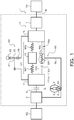
- the damper device 10 has a first torque transmission path TP1 and a second torque transmission path TP2 that are provided in parallel to each other between the drive member 11 and the driven member 15.
- the first torque transmission path TP1 is formed by the plurality of first springs SP1, the intermediate member 12 and the plurality of second springs SP2 and transmits the torque between the drive member 11 and the driven member 15 via these elements.
- coil springs having identical specifications are employed as the first springs SP1 and the second springs SP2 constituting the first torque transmission path TP1.
- Coil springs having different spring constants may be employed as the first springs SP1 and the second springs SP2.
- a turbine runner 5-side lateral portion of each of the inner springs SPi is placed in a center part in the circumferential direction of the corresponding inner spring placing window of the second input plate member 112 and is supported (guided) from outside in the radial direction by the spring support portion 112s of the second input plate member 112.
- the damper device 10 also includes a non-illustrated stopper configured to restrict the relative rotation between the drive member 11 and the driven member 15.
- the stopper restricts the relative rotation between the drive member 11 and the driven member 15 when the input torque into the drive member 11 reaches the torque T2 corresponding to the maximum torsion angle ⁇ max of the damper device 10. This results in restricting all deflections of the first springs SP1, the second springs SP2 and the inner springs SPi.
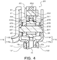
- the second input plate member 112 constituting the carrier of the planetary gear 21 includes a plurality of (for example, three according to the embodiment) pinion gear support portions 116 that are arranged at intervals (at equal intervals) in the circumferential direction on the outer side in the radial direction of the outer spring placing windows 112wo (outer spring contact portions).
- the ring gear 25 of the planetary gear 21 includes a ring-shaped gear main body 250 that has internal teeth 25t on its inner circumference; two side plates 251 that are respectively formed in an annular shape; and a plurality of rivets 252 that are provided to fix the respective side plates 251 to respective side surfaces in the axial direction of the gear main body 250.
- the gear main body 250, the two side plates 251 and the plurality of rivets 252 are integrated to serve as an inertial mass body (first mass body) of the rotary inertia mass damper 20.
- the internal teeth 25t is formed around the entire inner circumferential surface of the gear main body 250.
- the internal teeth 25t may be formed at a plurality of locations determined at intervals (at equal intervals) in the circumferential direction in the inner circumferential surface of the gear main body 250.
- Each of the side plates 251 serves as a supported portion that has an inner circumferential surface of a recessed cylindrical shape and that is supported in the axial direction by the plurality of pinion gears 23 engaging with the internal teeth 25t. More specifically, the two side plates 251 are fixed to corresponding side surfaces of the gear main body 250 on the respective sides in the axial direction of the internal teeth 25t such as to be protruded to an inner side in the radial direction of the bottoms of the internal teeth 25t and to be opposed to at least the side surfaces of the gear teeth 23t of the pinion gear 23. According to the embodiment, an inner circumferential surface of each side plate 251 is located on a slightly inner side in the radial direction of tips of the internal teeth 25t as shown in Fig. 4 .
- the ring gear 25 is accelerated by the function of the planetary gear 21 to be rotated at the higher rotation speed than that of the drive member 11.
- An inertia torque is then applied from the ring gear 25 that is the mass body of the rotary inertia mass damper 20 to the driven member 15 that is the output element of the damper device 10 via the pinion gears 23.
- This damps the vibration of the driven member 15.
- the rotary inertia mass damper 20 serves to mainly transmit the inertia torque between the drive member 11 and the driven member 15, while not transmitting the average torque.
- the turbine runner 5 and the like as the mass body and the plurality of inner springs SPi as the elastic body coupled with the turbine runner 5 and the like and with the driven member 15 constitute the dynamic damper 90, when the torsion angle of the drive member 11 relative to the driven member 15 is smaller than the predetermined angle ⁇ ref and the inner spring contact portions 111ci and 112ci of the first and the second input plate members 111 and 112 do not contact with the ends of the respective inner springs SPi.
- This dynamic damper 90 serves to apply a vibration in an opposite phase to the phase of the vibration of the driven member 15, to the driven member 15 and thereby damp the vibration of the driven member 15.
- two natural frequencies may be set in the state that the deflection of the first and the second springs SP1 and SP2 is allowed and the inner springs SPi is not deflected. More specifically, on the assumption that transmission of the torque from the engine EG to the drive member 11 is started in the established state of the lockup by the lockup clutch 8, resonance occurs due to vibrations of the drive member 11 and the driven member 15 in the opposite phases or resonance of mainly the transmission occurs between the drive member 11 and a non-illustrated driveshaft (first resonance, as shown by a resonance point R1 in Fig. 5 ) in the first torque transmission path TP1, in the state that the deflection of the first and the second springs SP1 and SP2 is allowed and the inner springs SPi is not deflected.
- first resonance as shown by a resonance point R1 in Fig. 5
- the phase of the vibration transmitted from the dynamic damper 90 to the driven member 15 becomes the same phase as the phase of the vibration transmitted from the first torque transmission path TP1 to the driven member 15 and the phase of the vibration transmitted from the rotary inertia mass damper 20 to the driven member 15.
- T 0 0 k 1 ⁇ ⁇ 2 J 1 + J i ⁇ 1 + ⁇ 2 ⁇ k 1 ⁇ 2 ⁇ J i ⁇ ⁇ ⁇ 1 + ⁇ ⁇ k 1 k 1 + k 2 ⁇ ⁇ 2 ⁇ J 2 ⁇ k 2 ⁇ 2 ⁇ J i ⁇ ⁇ ⁇ 1 + ⁇ ⁇ k 2 k 2 ⁇ ⁇ 2 J 3 + J i ⁇ ⁇ 2 ⁇ 1 ⁇ 2 ⁇ 3
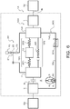
- the dynamic damper 90V serves to complement the inertia torque applied from the rotary inertia mass damper 20V to the driven member 15V and cancels at least part of the vibration transmitted from the first torque transmission path TP1 to the driven member 15V.
- the damper device 10V accordingly has the further improved vibration damping performance.
- This configuration also ensures the sufficient torsion angle of the springs SPd of the dynamic damper 90W and further improves the vibration damping performance of the dynamic damper 90W.
- This configuration also further increases the stiffness of the inner springs SPi and thereby further increases the maximum input torque of the damper device 10W.
- a minimum rotation speed (Nlup) in a rotation speed range where a torque is transmitted from the input element (11, 11Y, 11Z) to the output element (15, 15Y, 15Z, 15W) via the torque transmission path (TP1) may be lower than a rotation speed (Nea 1 ) corresponding to a minimum frequency (fa 1 ) among frequencies of antiresonance points (A1, A2) where a vibration amplitude of the output element (15, 15Y, 15Z, 15W) theoretically becomes equal to zero.
- the damper device of this aspect further reduces the vibration level in the lower rotation speed range than the low rotation-side antiresonance point. This accordingly further lowers the minimum rotation speed (lockup rotation speed) in the rotation range where the torque is transmitted to the output element via the torque transmission path and improves the transmission efficiency of power. This results in further improving the fuel consumption of the engine.
- the disclosure is applicable to, for example, the manufacturing industries of damper devices.
Landscapes
- Engineering & Computer Science (AREA)
- General Engineering & Computer Science (AREA)
- Mechanical Engineering (AREA)
- Physics & Mathematics (AREA)
- Acoustics & Sound (AREA)
- Aviation & Aerospace Engineering (AREA)
- Mechanical Operated Clutches (AREA)
Applications Claiming Priority (2)
| Application Number | Priority Date | Filing Date | Title |
|---|---|---|---|
| JP2016181669 | 2016-09-16 | ||
| PCT/JP2017/033073 WO2018052029A1 (fr) | 2016-09-16 | 2017-09-13 | Dispositif amortisseur |
Publications (2)
| Publication Number | Publication Date |
|---|---|
| EP3483471A1 true EP3483471A1 (fr) | 2019-05-15 |
| EP3483471A4 EP3483471A4 (fr) | 2020-04-01 |
Family
ID=61618825
Family Applications (1)
| Application Number | Title | Priority Date | Filing Date |
|---|---|---|---|
| EP17850930.3A Withdrawn EP3483471A4 (fr) | 2016-09-16 | 2017-09-13 | Dispositif amortisseur |
Country Status (6)
| Country | Link |
|---|---|
| US (1) | US11781618B2 (fr) |
| EP (1) | EP3483471A4 (fr) |
| JP (1) | JP6906742B2 (fr) |
| KR (1) | KR20190039252A (fr) |
| CN (1) | CN109715977B (fr) |
| WO (1) | WO2018052029A1 (fr) |
Families Citing this family (5)
| Publication number | Priority date | Publication date | Assignee | Title |
|---|---|---|---|---|
| CN112055792B (zh) * | 2018-03-30 | 2023-09-05 | 株式会社爱信福井 | 减震装置 |
| US11619270B2 (en) * | 2018-12-28 | 2023-04-04 | Valeo Kapec Co., Ltd. | Lock-up device for torque converter |
| DE102019121204A1 (de) * | 2019-02-27 | 2020-08-27 | Schaeffler Technologies AG & Co. KG | Torsionsschwingungsdämpfer mit einer Rotationsachse für einen Antriebsstrang |
| EP3951210A4 (fr) * | 2019-05-09 | 2023-01-25 | AISIN AW Industries CO., Ltd. | Dispositif amortisseur |
| CN113820111A (zh) * | 2021-09-16 | 2021-12-21 | 常州格林电力机械制造有限公司 | 一种阻尼器闭锁敏感性试验方法 |
Family Cites Families (11)
| Publication number | Priority date | Publication date | Assignee | Title |
|---|---|---|---|---|
| DE102010054249B4 (de) * | 2009-12-21 | 2023-11-30 | Schaeffler Technologies AG & Co. KG | Kraftübertragungsvorrichtung |
| JP2011214607A (ja) * | 2010-03-31 | 2011-10-27 | Aisin Aw Co Ltd | 流体伝動装置 |
| WO2012066680A1 (fr) * | 2010-11-19 | 2012-05-24 | トヨタ自動車株式会社 | Dispositif d'amortissement pour véhicule |
| WO2012066679A1 (fr) * | 2010-11-19 | 2012-05-24 | トヨタ自動車株式会社 | Dispositif d'amortissement de véhicule |
| CN103732943B (zh) * | 2011-10-05 | 2015-07-15 | 丰田自动车株式会社 | 动态减振装置 |
| JP5952432B2 (ja) * | 2013-01-30 | 2016-07-13 | アイシン・エィ・ダブリュ株式会社 | ダンパ装置および発進装置 |
| JP6197738B2 (ja) * | 2014-04-30 | 2017-09-20 | アイシン・エィ・ダブリュ株式会社 | 発進装置 |
| CN107110323B (zh) * | 2014-12-25 | 2019-09-10 | 爱信艾达工业株式会社 | 减振装置 |
| DE102015215888A1 (de) * | 2015-08-20 | 2017-02-23 | Schaeffler Technologies AG & Co. KG | Fliehkraftpendel und hydrodynamischer Drehmomentwandler mit Fliehkraftpendel |
| JP6315015B2 (ja) * | 2016-03-25 | 2018-04-25 | トヨタ自動車株式会社 | 捩り振動低減装置 |
| DE102019122692B4 (de) * | 2019-08-23 | 2021-06-10 | Schaeffler Technologies AG & Co. KG | Hydrodynamischer Drehmomentwandler mit Wandlerüberbrückungskupplung |
-
2017
- 2017-09-13 KR KR1020197007368A patent/KR20190039252A/ko not_active Ceased
- 2017-09-13 US US16/327,546 patent/US11781618B2/en active Active
- 2017-09-13 EP EP17850930.3A patent/EP3483471A4/fr not_active Withdrawn
- 2017-09-13 CN CN201780056568.7A patent/CN109715977B/zh active Active
- 2017-09-13 JP JP2018539755A patent/JP6906742B2/ja active Active
- 2017-09-13 WO PCT/JP2017/033073 patent/WO2018052029A1/fr not_active Ceased
Also Published As
| Publication number | Publication date |
|---|---|
| CN109715977B (zh) | 2021-08-24 |
| US11781618B2 (en) | 2023-10-10 |
| EP3483471A4 (fr) | 2020-04-01 |
| JP6906742B2 (ja) | 2021-07-21 |
| KR20190039252A (ko) | 2019-04-10 |
| CN109715977A (zh) | 2019-05-03 |
| JPWO2018052029A1 (ja) | 2019-06-24 |
| WO2018052029A1 (fr) | 2018-03-22 |
| US20190203800A1 (en) | 2019-07-04 |
Similar Documents
| Publication | Publication Date | Title |
|---|---|---|
| US20190301563A1 (en) | Damper device | |
| KR102005165B1 (ko) | 댐퍼 장치 | |
| JP6781791B2 (ja) | ダンパ装置 | |
| US10208832B2 (en) | Centrifugal pendulum-type vibration absorbing device and designing method for the same | |
| EP3483471A1 (fr) | Dispositif amortisseur | |
| US10718401B2 (en) | Damper device | |
| EP3159574B1 (fr) | Dispositif amortisseur | |
| US20180080523A1 (en) | Damper device | |
| US20190203801A1 (en) | Damper device | |
| US10746254B2 (en) | Damper device | |
| US10487909B2 (en) | Damper device | |
| US20190264773A1 (en) | Damper device |
Legal Events
| Date | Code | Title | Description |
|---|---|---|---|
| PUAI | Public reference made under article 153(3) epc to a published international application that has entered the european phase |
Free format text: ORIGINAL CODE: 0009012 |
|
| STAA | Information on the status of an ep patent application or granted ep patent |
Free format text: STATUS: REQUEST FOR EXAMINATION WAS MADE |
|
| 17P | Request for examination filed |
Effective date: 20190207 |
|
| AK | Designated contracting states |
Kind code of ref document: A1 Designated state(s): AL AT BE BG CH CY CZ DE DK EE ES FI FR GB GR HR HU IE IS IT LI LT LU LV MC MK MT NL NO PL PT RO RS SE SI SK SM TR |
|
| AX | Request for extension of the european patent |
Extension state: BA ME |
|
| DAV | Request for validation of the european patent (deleted) | ||
| DAX | Request for extension of the european patent (deleted) | ||
| A4 | Supplementary search report drawn up and despatched |
Effective date: 20200303 |
|
| RIC1 | Information provided on ipc code assigned before grant |
Ipc: F16F 15/134 20060101ALI20200226BHEP Ipc: F16F 15/131 20060101ALI20200226BHEP Ipc: F16F 15/12 20060101ALI20200226BHEP Ipc: F16H 45/02 20060101ALI20200226BHEP Ipc: F16F 15/14 20060101AFI20200226BHEP Ipc: F16F 15/123 20060101ALI20200226BHEP |
|
| STAA | Information on the status of an ep patent application or granted ep patent |
Free format text: STATUS: THE APPLICATION IS DEEMED TO BE WITHDRAWN |
|
| 18D | Application deemed to be withdrawn |
Effective date: 20201001 |