EP3483513A1 - Procédé de fonctionnement d'une installation de chauffage et installation de chauffage - Google Patents
Procédé de fonctionnement d'une installation de chauffage et installation de chauffage Download PDFInfo
- Publication number
- EP3483513A1 EP3483513A1 EP18199318.9A EP18199318A EP3483513A1 EP 3483513 A1 EP3483513 A1 EP 3483513A1 EP 18199318 A EP18199318 A EP 18199318A EP 3483513 A1 EP3483513 A1 EP 3483513A1
- Authority
- EP
- European Patent Office
- Prior art keywords
- heating
- time
- temperature
- room temperature
- parameters
- Prior art date
- Legal status (The legal status is an assumption and is not a legal conclusion. Google has not performed a legal analysis and makes no representation as to the accuracy of the status listed.)
- Granted
Links
Images

Classifications
-
- F—MECHANICAL ENGINEERING; LIGHTING; HEATING; WEAPONS; BLASTING
- F24—HEATING; RANGES; VENTILATING
- F24D—DOMESTIC- OR SPACE-HEATING SYSTEMS, e.g. CENTRAL HEATING SYSTEMS; DOMESTIC HOT-WATER SUPPLY SYSTEMS; ELEMENTS OR COMPONENTS THEREFOR
- F24D19/00—Details
- F24D19/10—Arrangement or mounting of control or safety devices
- F24D19/1006—Arrangement or mounting of control or safety devices for water heating systems
- F24D19/1009—Arrangement or mounting of control or safety devices for water heating systems for central heating
-
- G—PHYSICS
- G05—CONTROLLING; REGULATING
- G05D—SYSTEMS FOR CONTROLLING OR REGULATING NON-ELECTRIC VARIABLES
- G05D23/00—Control of temperature
- G05D23/19—Control of temperature characterised by the use of electric means
- G05D23/1902—Control of temperature characterised by the use of electric means characterised by the use of a variable reference value
- G05D23/1904—Control of temperature characterised by the use of electric means characterised by the use of a variable reference value variable in time
-
- G—PHYSICS
- G05—CONTROLLING; REGULATING
- G05D—SYSTEMS FOR CONTROLLING OR REGULATING NON-ELECTRIC VARIABLES
- G05D23/00—Control of temperature
- G05D23/19—Control of temperature characterised by the use of electric means
- G05D23/1927—Control of temperature characterised by the use of electric means using a plurality of sensors
- G05D23/193—Control of temperature characterised by the use of electric means using a plurality of sensors sensing the temperaure in different places in thermal relationship with one or more spaces
- G05D23/1932—Control of temperature characterised by the use of electric means using a plurality of sensors sensing the temperaure in different places in thermal relationship with one or more spaces to control the temperature of a plurality of spaces
- G05D23/1934—Control of temperature characterised by the use of electric means using a plurality of sensors sensing the temperaure in different places in thermal relationship with one or more spaces to control the temperature of a plurality of spaces each space being provided with one sensor acting on one or more control means
-
- Y—GENERAL TAGGING OF NEW TECHNOLOGICAL DEVELOPMENTS; GENERAL TAGGING OF CROSS-SECTIONAL TECHNOLOGIES SPANNING OVER SEVERAL SECTIONS OF THE IPC; TECHNICAL SUBJECTS COVERED BY FORMER USPC CROSS-REFERENCE ART COLLECTIONS [XRACs] AND DIGESTS
- Y02—TECHNOLOGIES OR APPLICATIONS FOR MITIGATION OR ADAPTATION AGAINST CLIMATE CHANGE
- Y02B—CLIMATE CHANGE MITIGATION TECHNOLOGIES RELATED TO BUILDINGS, e.g. HOUSING, HOUSE APPLIANCES OR RELATED END-USER APPLICATIONS
- Y02B30/00—Energy efficient heating, ventilation or air conditioning [HVAC]
- Y02B30/70—Efficient control or regulation technologies, e.g. for control of refrigerant flow, motor or heating
Definitions
- the present invention relates to a method for operating a heating system in a building.
- the method is intended to determine a point in time at which a heating process must start in order to heat a room to a specific desired value up to a predetermined later point in time.
- the invention relates to a heating system.
- setpoints of the room temperature can be specified for fixed times.
- a heating system can be configured so that the room temperature is lowered overnight until the next morning at a certain time again a higher setpoint is to be achieved.
- the heating process must be started soon enough.
- the time required for heating can be calculated by the heating control, which generally depends on a large number of parameters. Some such methods are already known in the art.
- the time required for heating a room to a predetermined setpoint temperature is also referred to below as the heating-up time.
- a generic method for operating a smart thermostat known.
- the method includes storing a current value for an environmental parameter. If the stored environment parameter values match a local model for changing the parameter over time, a remaining response time is determined using a local model. The determined reaction time is stored and the remaining reaction time is displayed in a display device. If the environmental parameter values do not match a local model but a global model, a remaining response time is determined using the global model and the response time is stored and the remaining response time displayed on the display device. For example, the remaining time for heating a room to a desired value can be determined as the reaction time.
- the US patent application US 2010/0318227 A1 discloses generic systems and methods for reducing a cycle time of an air conditioner.
- one or more of the example systems may receive from a database a target time when a particular target temperature is to be reached.
- the system detects the temperature inside and outside the building.
- a thermal characteristic of the building and a performance feature of the air conditioning system are used to determine the appropriate time before the time of arrival to which the air conditioner is to turn on.
- EP 2 369 244 A1 a generic method for the timely achievement of temperature setpoints by a heating process in a heating system of a building is described.
- the method comprises determining one or more target times at which the temperature setpoints to be achieved by the heating process are to be achieved. Furthermore, a time required to reach the temperature setpoints is determined using the power of the heat generator and / or the ambient conditions. Subsequently, a start time of the heating process is determined from the specified target times and the determined period of time.
- the present invention has the object to provide a comparison with the prior art improved method for operating a heating system and in particular for determining the heating time.
- the object of the invention is achieved by a method for operating a heating system according to the preamble of claim 1.
- a multiplicity of parameters is determined as a function of a multiplicity of recorded measured values, whereby only those measured values from a defined period of time are generated, which generates during a heating process were measured values of a time then belong to a heating process, if the current Jardinisttemperatur is less than the current room set temperature.
- the method can be used in particular for operating a heating system with individual room control or with reference space control.
- a heating system with individual room control the method can be used for each of a variety of rooms, so that for each room a heating time can be determined and the large number of parameters depending on the characteristics of each room.
- the method is applied only to the reference room.
- the second point in time at which the heating process must start in order to reach the specified target temperature at the first time is before the first time.
- the time from the second time to the first time gives the heating time.
- the purpose of the method is to determine the second time, so that a control or regulating device of the heating system or a room thermostat at this time can initiate the heating of the room.
- the aim of the invention is to optimize the determination of this second time, so that the second time can be determined with a higher accuracy.
- the determination of the plurality of parameters takes place in dependence on a multiplicity of recorded measured values from a defined period of time.
- the measured values recorded periodically at predetermined times are present in particular as a time series.
- a large number of historical measured values can be selected for the evaluation, that is to say for the determination of the multiplicity of parameters.
- the period does not have to be contiguous. It can be evaluated a variety of historical measurements to determine the variety of parameters.
- By evaluating the historical measured values it is possible to derive properties of the room that have an influence on the heating-up time, for example using a model which, inter alia, can take into account heat losses from the relevant room and external heat input into the room.
- the heating behavior of the room can be analyzed by a statistical evaluation of historical measured values and a comparison with a model. For this purpose, however, only those measured values are to be used which were generated during heating processes.
- a criterion for detecting a heating process is, in particular, that the room actual temperature is less than the current desired room temperature. To detect the heating processes, it may be sufficient to evaluate the measured values of the actual room temperature and the set room temperature.
- the measured values are preferably recorded centrally as a time series by a regulating or control device of the heating system.
- the heating system may include suitable means for detecting the Jardinisttemperatur, the desired room temperature, the flow temperature and the outside temperature, which may be connected to the control or regulating device.
- a room temperature sensor is arranged in the at least one heatable space.
- an outside temperature sensor may be located at a suitable location outside the building. Alternatively, the outside temperature can be received from a weather station or from the Internet.
- a flow temperature sensor can be arranged in the flow.
- the heating system may have an interface for communicating with a computing device.
- the computing device may be, for example, a geographically remote computer.
- the geographically remote computer can be, for example, a server, a computer network or computer cloud ("cloud").
- cloud computer network
- a corresponding cloud computing service provider can be used for this purpose.
- server is used in a summary for the various alternatives.
- the heating system or a regulating or control device of the heating system can transmit the recorded measured values to the server, so that the step of determining the plurality of parameters is carried out by the server.
- Geographically distant means that the location of the server is independent of the location of the heating system.
- a suitable communication line such as an Internet connection, to which the heating system can be connected, for example via a gateway, can be used.
- a condition for a heating operation may be that the heating operation is longer than a first predetermined period of time.
- the first predetermined period may be a few minutes, for example five to ten or fifteen minutes. In this way it can be ensured that only those measured values are selected that actually belong to a heating process and not to a random temporal temperature fluctuation.
- a certain minimum duration is advantageous since then there is a sufficiently large number of measured values for a statistical evaluation.
- a criterion for selecting a heating process it can be stipulated that, at the start of the heating process, the difference between the current desired room temperature and the current room actual temperature is greater than a threshold, which is at least 0.5 K, for example.
- a threshold which is at least 0.5 K, for example.
- Another criterion for selecting a heating process may be that the actual room temperature is reduced by at most 0.1 K within a second predetermined period of time. In this way, it can be achieved that only such time series of measured values are recognized as heating processes in which the actual room temperature rises essentially monotonically.
- the second predetermined period of time may be a duration of several minutes, for example five to ten minutes.
- the heating processes used in determining the plurality of parameters can be divided into at least two shorter time heating processes, each having at least a duration of a third predetermined period.
- the third period must be shorter than the first period.
- the third period is one half, one third, one quarter or one fifth of the first period.
- the determination of the plurality of parameters may preferably be carried out using a linear regression model.
- a process of machine learning can be implemented to create a model of the room to be heated, or to adapt a model to the properties of the room to be heated. Since the heat losses occurring in a room and any external heat input (for example due to solar radiation that heats the room through a window) can not easily be calculated and taken into account in a model, an existing model is adapted to actual measured values. The deviation between the measured data and the data generated by the model should be as small as possible.
- a model used here has a large number of model parameters that can be optimized via a linear regression.
- the object of the invention is also achieved by a heating system which is configured to carry out the method according to the invention.
- the heating system is arranged in a building with at least one heatable space having at least one radiator.
- the heating system comprises a control device for regulating the temperature in the at least one heatable space to a predetermined desired room temperature and a measuring device for determining the room temperature.
- the heating system further comprises a heat generator for heating a carrier medium, which flows via a flow to the at least one radiator and flows via a return to the heat generator. In the flow means for detecting a current flow temperature are arranged.
- the heating system comprises means for detecting a current Jardinisttemperatur the at least one heatable space, means for setting the desired room temperature for the at least one heatable space, means for detecting an outdoor temperature and means for setting a target temperature in the at least one heatable space to a first Time to be achieved.
- the heating system is configured to periodically generate and record the temperature measurement values at predetermined times and to determine a second time point at which a heating process must start in order to start the heating process at the first time Target temperature to reach. The determination of the second time occurs in dependence on a plurality of parameters.
- the heating system is configured to determine the plurality of parameters in dependence on a multiplicity of recorded measured values, whereby only those measured values from a defined period of time which were generated during a heating process are used, wherein the measured values of those times belong to a heating process to which current room temperature is less than the currently specified room set temperature.
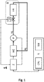
- Fig. 1 shows an embodiment of a heating system 1 according to the invention for a building with at least one heatable space R, which has at least one radiator HK.
- the building may include other heatable and / or unheated rooms.
- the heating system 1 has a heat generator WE, which may be, for example, a hot water boiler operated with gas, fuel oil, wood or other fuel can. About a flow VL flows from the heat generator WE heated fluid heat transfer medium, such as water, to the radiator HK in space R. About a return RL the heat transfer medium from the radiator HK flows back to the heat generator WE.
- a pump P is arranged for example in the flow VL.
- the pump P may be arranged instead of the flow VL in the return RL or in the heat generator WE itself.
- the delivery rate of the pump P can be controlled or regulated, for example, via the pump speed.
- Via a temperature sensor not shown, a flow temperature T VL of the heat transfer medium in the flow VL is measured.
- the heating system 1 may further comprise an outside temperature sensor for detecting an outside temperature T A.
- a room thermostat TH is arranged for controlling the room temperature.
- the room thermostat TH has a room temperature sensor for detecting the actual room temperature T R and a room temperature controller for regulating the room temperature to a predetermined desired room temperature T R, W on.
- the room temperature controller can control an actuator which determines the degree of opening of a valve of the radiator HK as an actuator for setting a mass flow or a volume flow of the heat transfer medium through the radiator HK.
- the heating system 1 also has a central control or regulating device Z for controlling and / or regulating the heat generator WE.
- the central control or regulating device Z can also be configured to control and / or regulate the pump. Via wired or wireless communication lines, the control or regulating device Z can transmit setpoint specifications to the room thermostat TH.
- a heating system 1 can also be designed for heating a multiplicity of heatable rooms.
- the room temperature control can be done for example in one of two different common types. With individual room control, a separate room set temperature can be specified separately for each room. In this case, each room has its own room thermostat for regulating the room temperature to the setpoint.
- the method according to the invention for which an embodiment is described below, can then be carried out separately for each room.
- a room can serve as a reference room. In this case, the procedure is performed only for this one room.
- the heating system 1 is connected via a communication interface and a suitable communication line with a geographically remote server S.
- the control or regulating device Z can be connected to the Internet via a gateway.
- the server S may have at least one processor CPU and at least one storage medium SM.
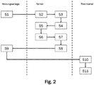
- Fig. 2 shows a flowchart of an exemplary embodiment of the method according to the invention.
- the heating system records 1 measured values.
- the measurement values are recorded periodically at fixed times, for example at a frequency of at least once per five minutes to at least once per second.
- the measured values include at least the current actual room temperature T R of the at least one heatable room R and the room temperature T R, W currently preset for the at least one heatable room R together with the time of the measurement.
- the current outside temperature T A and the current flow temperature T VL can be recorded as further measured values.
- the measured values can, for example, first be temporarily stored in a buffer memory in the central control or control device Z and then transmitted to the server S.
- the transmission of the measured values to the server S can be carried out, for example, at fixed times at least once a day or several times a day.
- the measured values are in particular transmitted to the server S as a time series of measured values.
- the transmission of the measured values to the server S can also always take place when a certain number of recorded measured values are present in the buffer memory of the central control or regulating device Z.
- it is also possible to transmit the measured values in real time so that the measured values are transmitted to the server S immediately or as quickly as possible.
- the transmitted measured values can also be formatted in the server S to a time series.
- the measured values can each have a time stamp, by means of which the time of generation of the respective measured value can be identified.
- the server S receives the transmitted measured values and stores them locally in the storage medium SM in step S3.
- the server S can also perform a conversion of the measured values or a sorting of the measured values according to times.
- the following steps S3 to S8 are all performed by the server S.
- the server can in a further step S4 summarize the measured values into packages of time series of 24 hours each.
- a database of measured values sorted by days can be created so that a subsequent evaluation of the measured values is facilitated.
- stored data records can be accessed specifically for generating and testing model parameters.
- step S5 an identification of heating operations is first performed.
- all last transmitted measured values can be evaluated here.
- a period ⁇ t H can be determined, from which the stored measured values are to be evaluated.
- the period ⁇ t H may, for example, include one to several days.
- the period ⁇ t H to be analyzed does not have to be contiguous. For example, several days can be selected with similar outlines of the outside temperature.
- all stored measured values can also be analyzed.
- the heating processes are identified by checking one or more conditions.
- a first condition for the presence of a heating process is that the recorded actual room temperature of a time is less than the predetermined desired room temperature of the time.
- the end of a heating process is marked by the time in which the actual room temperature is at least equal to the desired room temperature.
- a hysteresis can be taken into account. However, as this only causes an offset, it is assumed in the following that no hysteresis is to be taken into account.
- Fig. 3 is a time series of measured values of the actual room temperature T R plotted as a curve over time.
- the actual room temperature T R fluctuates around a value of approximately 18 ° C.
- the desired room temperature T R, W is set to a value of 22 ° C, so that from this time the Jardinisttemperatur T R is initially smaller than the desired room temperature T R, W is.
- the time 0 thus marks the beginning of a heating process, which in Fig. 3 marked as a white triangle.
- the actual room temperature T R reaches the predetermined value of the desired room temperature T R, W of 22 ° C. This time marks the end of the heating process and is in Fig. 3 characterized by a black triangle. All points of the shown room temperature curve between the white and the black triangle now belong to the identified heating process and can be used in the following further data evaluation.
- a plurality of heating processes can be identified from the plurality of measured values. For the calculation of parameters for determining a heating time, it may be useful to provide further conditions for the heating processes. According to a first additional condition at a heating operation can be specified that the heating t is longer than a first predetermined period of time to ⁇ 1.
- This first predetermined Period ⁇ t 1 can for example be at least five minutes to thirty minutes, preferably ten, fifteen or twenty minutes.
- a second additional condition to a heating process can be specified that the difference between the current desired room temperature T R, W and actual Kunststoffisttemperatur T R at the beginning of the heating process is at least 0.5 K to at least 1 K.
- the difference between the current desired room temperature T R, W and actual Kunststoffisttemperatur T R at the beginning of the heating process is at least 0.5 K to at least 1 K.
- a third additional condition at a heating operation can be specified that the actual room temperature T R during the heating operation by more than 0,1 K within a second predetermined period of time ⁇ t 2 is decreased.
- the second predetermined period of time ⁇ t 2 may be a few minutes, for example, be five minutes. This predetermined maximum temperature drop ensures that the heating processes have a substantially monotonous increase in temperature, which is advantageous in the subsequent data evaluation.
- the three additional conditions described above may each be used individually or in any combination to identify suitable heating processes for the data evaluation.
- step S6 a division of the heating processes can be carried out in step S6 in order to further increase the number of evaluable heating processes.
- This step S6 is also called subsampling.
- a high number of heating processes is particularly advantageous in a statistical evaluation.
- the temporal subdivision can be carried out, for example, in fixed time steps of a few minutes.
- the splitting of the heating processes can also be carried out on the basis of predetermined temperature differences, for example in increments of 0.5 K to 1 K.
- the plurality of parameters is determined in step S7.
- the plurality of parameters can be determined in particular by training a heating system-specific model, preferably a model of the linear regression, using the heating processes previously identified in S6. Training the model in this context means that the multitude of parameters can be determined as coefficients of a mathematical model. Here, the previously identified heating operations are compared with calculated values of the model and the deviation between the calculated values and the measured values is minimized by varying the coefficients.
- T S is the start temperature of a heating process
- T E is the end temperature of a heating process
- T VL is the flow temperature during the heating process
- T A is the outside temperature during the heating process.
- the parameters ⁇ 1 , ⁇ 2 , ⁇ 3 , ⁇ 4 can be extracted from the model and stored for further use in the storage medium SM of the server.
- the determined parameters are transmitted to the heating system 1.
- the heating system 1 receives the determined parameters in step S9.
- the central control or control unit Z of the heating system 1 can calculate the heating time of the at least one heatable space R based on the determined parameters, so that when setting a desired room temperature T E for a certain time t E in the future, an optimal time t S to start of the heating process can be determined.
- the determination of the heating time can also be carried out by a room thermostat TH.
- the central control or control unit Z can pass on the multiplicity of parameters in step S10 to at least one intelligent room thermostat TH. If the central control unit Z determines the heating times, it forwards them to the room thermostat TH in step S10.
- the room thermostat TH uses the determined heating times in step S11.
- Fig. 4 By way of example, two temporal courses of the room temperature are shown.
- the dashed curve T ' R illustrates the time course of the room temperature without determining the heating time.
- the desired room temperature T E is specified.
- the heating process begins.
- the solid curve T R illustrates the time course of the room temperature with determining the heating time. In order to reach the desired room temperature T E at time t E , the heating process is already started at time t S.
Landscapes
- Engineering & Computer Science (AREA)
- Physics & Mathematics (AREA)
- General Physics & Mathematics (AREA)
- Automation & Control Theory (AREA)
- Thermal Sciences (AREA)
- Chemical & Material Sciences (AREA)
- Combustion & Propulsion (AREA)
- Mechanical Engineering (AREA)
- General Engineering & Computer Science (AREA)
- Remote Sensing (AREA)
- Air Conditioning Control Device (AREA)
- Steam Or Hot-Water Central Heating Systems (AREA)
Applications Claiming Priority (1)
| Application Number | Priority Date | Filing Date | Title |
|---|---|---|---|
| DE102017220097.9A DE102017220097A1 (de) | 2017-11-10 | 2017-11-10 | Verfahren zum Betreiben einer Heizungsanlage |
Publications (2)
| Publication Number | Publication Date |
|---|---|
| EP3483513A1 true EP3483513A1 (fr) | 2019-05-15 |
| EP3483513B1 EP3483513B1 (fr) | 2021-08-18 |
Family
ID=63832188
Family Applications (1)
| Application Number | Title | Priority Date | Filing Date |
|---|---|---|---|
| EP18199318.9A Active EP3483513B1 (fr) | 2017-11-10 | 2018-10-09 | Procédé de fonctionnement d'une installation de chauffage et installation de chauffage |
Country Status (2)
| Country | Link |
|---|---|
| EP (1) | EP3483513B1 (fr) |
| DE (1) | DE102017220097A1 (fr) |
Families Citing this family (1)
| Publication number | Priority date | Publication date | Assignee | Title |
|---|---|---|---|---|
| DE102023107267A1 (de) * | 2023-03-23 | 2024-09-26 | Oventrop Gmbh & Co. Kg | Verfahren zur Einstellung eines hydraulischen Abgleichs |
Citations (8)
| Publication number | Priority date | Publication date | Assignee | Title |
|---|---|---|---|---|
| DE4241858A1 (de) * | 1992-12-11 | 1994-06-16 | Buderus Heiztechnik Gmbh | Verfahren zum optimierten Anfahren einer Heizungsanlage |
| GB2278207A (en) * | 1993-05-17 | 1994-11-23 | Ea Tech Ltd | Heating control apparatus |
| US20100318227A1 (en) | 2009-05-08 | 2010-12-16 | Ecofactor, Inc. | System, method and apparatus for just-in-time conditioning using a thermostat |
| EP2369244A1 (fr) | 2010-03-10 | 2011-09-28 | Rehau AG & Co | Procédé d'obtention à temps de températures de consigne par le biais d'un ou plusieurs procédés de chauffage dans une installation de chauffage de bâtiment |
| DE102010056301A1 (de) * | 2010-12-24 | 2012-06-28 | Robert Bosch Gmbh | Verfahren zur automatischen Optimierung eines Heizsystems sowie Heizsystem |
| WO2013058966A1 (fr) | 2011-10-21 | 2013-04-25 | Nest Labs, Inc. | Contrôleur intelligent générant un temps par rapport à un état cible |
| CN105805822A (zh) * | 2016-03-24 | 2016-07-27 | 常州英集动力科技有限公司 | 基于神经网络预测的供热节能控制方法与系统 |
| US20160283844A1 (en) * | 2015-03-27 | 2016-09-29 | Optimum Energy Llc | Load predictor for a cooling system |
Family Cites Families (2)
| Publication number | Priority date | Publication date | Assignee | Title |
|---|---|---|---|---|
| DE2855227C2 (de) * | 1978-12-21 | 1982-04-15 | Honeywell Gmbh, 6000 Frankfurt | Verfahren zum Optimieren des Energieverbrauches in Gebäuden sowie Anordnung zur Durchführung des Verfahrens |
| DE2912569A1 (de) * | 1979-03-29 | 1980-10-09 | Honeywell Gmbh | Verfahren und einrichtung zur heizungs- oder klimaregelung |
-
2017
- 2017-11-10 DE DE102017220097.9A patent/DE102017220097A1/de not_active Ceased
-
2018
- 2018-10-09 EP EP18199318.9A patent/EP3483513B1/fr active Active
Patent Citations (8)
| Publication number | Priority date | Publication date | Assignee | Title |
|---|---|---|---|---|
| DE4241858A1 (de) * | 1992-12-11 | 1994-06-16 | Buderus Heiztechnik Gmbh | Verfahren zum optimierten Anfahren einer Heizungsanlage |
| GB2278207A (en) * | 1993-05-17 | 1994-11-23 | Ea Tech Ltd | Heating control apparatus |
| US20100318227A1 (en) | 2009-05-08 | 2010-12-16 | Ecofactor, Inc. | System, method and apparatus for just-in-time conditioning using a thermostat |
| EP2369244A1 (fr) | 2010-03-10 | 2011-09-28 | Rehau AG & Co | Procédé d'obtention à temps de températures de consigne par le biais d'un ou plusieurs procédés de chauffage dans une installation de chauffage de bâtiment |
| DE102010056301A1 (de) * | 2010-12-24 | 2012-06-28 | Robert Bosch Gmbh | Verfahren zur automatischen Optimierung eines Heizsystems sowie Heizsystem |
| WO2013058966A1 (fr) | 2011-10-21 | 2013-04-25 | Nest Labs, Inc. | Contrôleur intelligent générant un temps par rapport à un état cible |
| US20160283844A1 (en) * | 2015-03-27 | 2016-09-29 | Optimum Energy Llc | Load predictor for a cooling system |
| CN105805822A (zh) * | 2016-03-24 | 2016-07-27 | 常州英集动力科技有限公司 | 基于神经网络预测的供热节能控制方法与系统 |
Also Published As
| Publication number | Publication date |
|---|---|
| DE102017220097A1 (de) | 2019-05-16 |
| EP3483513B1 (fr) | 2021-08-18 |
Similar Documents
| Publication | Publication Date | Title |
|---|---|---|
| DE102017205033B4 (de) | Verfahren und System zum internetgestützten Optimieren von Parametern einer Heizungsregelung | |
| DE4108310A1 (de) | Wissensbank-verarbeitungssystem und expertensystem | |
| EP3646122B1 (fr) | Procédé et dispositif servant à régler au moins un paramètre d'un système de régulation d'actionneur et système de régulation d'actionneur | |
| DE102007030492A1 (de) | Gebäudemodellbasiertes prädiktives Regelverfahren zum Heizen eines begrenzten Systems | |
| EP2009536B1 (fr) | Procédé et dispositif destinés à l'ajustage de la réserve de puissance de chauffe | |
| EP3698223B1 (fr) | Procédé et dispositif pour faire fonctionner un système de régulation d'actionneur, programme d'ordinateur et support de stockage lisible par machine | |
| DE3243198A1 (de) | Verfahren zur ermittlung des waermeverbrauchs von heizkoerpern und vorrichtung zur durchfuehrung des verfahrens zum zwecke der heizkostenverteilung | |
| EP3483513B1 (fr) | Procédé de fonctionnement d'une installation de chauffage et installation de chauffage | |
| DE102005051203B3 (de) | Verfahren zur Bestimmung des Heizwärmebedarfs eines Gebäudes | |
| EP3942372B1 (fr) | Procédé de validation de paramètres de système d'un système énergétique, procédé pour faire fonctionner un système énergétique et système de gestion d'énergie pour un système énergétique | |
| EP3599583A1 (fr) | Détermination de la consommation de l'énergie de chauffage ou de refroidissement d'une sous-unité de construction | |
| DE102015113340A1 (de) | Heizungsanlage und Verfahren zum Betreiben einer Heizungsanlage | |
| EP4036484B1 (fr) | Installation de chauffage et procédé de fonctionnement d'une installation de chauffage | |
| EP2591647B1 (fr) | Dispositif électronique doté d' un dispositif de refroidissement | |
| DE102023209111A1 (de) | Verfahren zum Durchführen eines hydraulischen Abgleichs einer Heizungsanlage | |
| EP3035144B1 (fr) | Procédé et dispositif pour contrôler la décharge d'énergie thermique dans des structures résidentielles locales et régionales | |
| WO2018224222A1 (fr) | Procédé de fonctionnement d'un système de consommation thermique | |
| EP3009908B1 (fr) | Procédé et agencement de dispositif destinés à enregistrer, évaluer et influencer la répartition de la distribution des énergies de chauffage au sein d'une enveloppe de bâtiment | |
| EP4474785B1 (fr) | Procédé de détermination de la température ambiante | |
| EP4343213B1 (fr) | Procédé de réalisation d'un équilibrage hydraulique d'une installation de chauffage | |
| DE102018110044B4 (de) | Verfahren und Vorrichtung zum aufeinander abgestimmten Betreiben von elektrischen Einrichtungen | |
| EP4027211A1 (fr) | Procédé d'optimisation d'une courbe de chauffage et système de chauffage | |
| EP4660553A1 (fr) | Procédé mis en uvre par ordinateur pour régler au moins un paramètre relatif à un dispositif de chauffage | |
| EP4522919A1 (fr) | Procédé de surveillance et/ou de commande d'un système de chauffage | |
| EP2950277A1 (fr) | Système d'exploitation et procédé de fonctionnement d'un tel système d'exploitation |
Legal Events
| Date | Code | Title | Description |
|---|---|---|---|
| PUAI | Public reference made under article 153(3) epc to a published international application that has entered the european phase |
Free format text: ORIGINAL CODE: 0009012 |
|
| STAA | Information on the status of an ep patent application or granted ep patent |
Free format text: STATUS: THE APPLICATION HAS BEEN PUBLISHED |
|
| AK | Designated contracting states |
Kind code of ref document: A1 Designated state(s): AL AT BE BG CH CY CZ DE DK EE ES FI FR GB GR HR HU IE IS IT LI LT LU LV MC MK MT NL NO PL PT RO RS SE SI SK SM TR |
|
| AX | Request for extension of the european patent |
Extension state: BA ME |
|
| RIN1 | Information on inventor provided before grant (corrected) |
Inventor name: METZGER, JAN Inventor name: MARX, LYNN Inventor name: STUMPF, BIANCA Inventor name: FASSNACHT, TILLMAN |
|
| STAA | Information on the status of an ep patent application or granted ep patent |
Free format text: STATUS: REQUEST FOR EXAMINATION WAS MADE |
|
| 17P | Request for examination filed |
Effective date: 20191115 |
|
| RBV | Designated contracting states (corrected) |
Designated state(s): AL AT BE BG CH CY CZ DE DK EE ES FI FR GB GR HR HU IE IS IT LI LT LU LV MC MK MT NL NO PL PT RO RS SE SI SK SM TR |
|
| GRAP | Despatch of communication of intention to grant a patent |
Free format text: ORIGINAL CODE: EPIDOSNIGR1 |
|
| STAA | Information on the status of an ep patent application or granted ep patent |
Free format text: STATUS: GRANT OF PATENT IS INTENDED |
|
| INTG | Intention to grant announced |
Effective date: 20210319 |
|
| RAP1 | Party data changed (applicant data changed or rights of an application transferred) |
Owner name: VIESSMANN CLIMATE SOLUTIONS SE |
|
| GRAS | Grant fee paid |
Free format text: ORIGINAL CODE: EPIDOSNIGR3 |
|
| GRAA | (expected) grant |
Free format text: ORIGINAL CODE: 0009210 |
|
| STAA | Information on the status of an ep patent application or granted ep patent |
Free format text: STATUS: THE PATENT HAS BEEN GRANTED |
|
| AK | Designated contracting states |
Kind code of ref document: B1 Designated state(s): AL AT BE BG CH CY CZ DE DK EE ES FI FR GB GR HR HU IE IS IT LI LT LU LV MC MK MT NL NO PL PT RO RS SE SI SK SM TR |
|
| REG | Reference to a national code |
Ref country code: GB Ref legal event code: FG4D Free format text: NOT ENGLISH |
|
| REG | Reference to a national code |
Ref country code: CH Ref legal event code: EP |
|
| REG | Reference to a national code |
Ref country code: DE Ref legal event code: R096 Ref document number: 502018006615 Country of ref document: DE |
|
| REG | Reference to a national code |
Ref country code: IE Ref legal event code: FG4D Free format text: LANGUAGE OF EP DOCUMENT: GERMAN Ref country code: AT Ref legal event code: REF Ref document number: 1421973 Country of ref document: AT Kind code of ref document: T Effective date: 20210915 |
|
| REG | Reference to a national code |
Ref country code: NL Ref legal event code: FP |
|
| REG | Reference to a national code |
Ref country code: SE Ref legal event code: TRGR |
|
| REG | Reference to a national code |
Ref country code: LT Ref legal event code: MG9D |
|
| PG25 | Lapsed in a contracting state [announced via postgrant information from national office to epo] |
Ref country code: RS Free format text: LAPSE BECAUSE OF FAILURE TO SUBMIT A TRANSLATION OF THE DESCRIPTION OR TO PAY THE FEE WITHIN THE PRESCRIBED TIME-LIMIT Effective date: 20210818 Ref country code: HR Free format text: LAPSE BECAUSE OF FAILURE TO SUBMIT A TRANSLATION OF THE DESCRIPTION OR TO PAY THE FEE WITHIN THE PRESCRIBED TIME-LIMIT Effective date: 20210818 Ref country code: FI Free format text: LAPSE BECAUSE OF FAILURE TO SUBMIT A TRANSLATION OF THE DESCRIPTION OR TO PAY THE FEE WITHIN THE PRESCRIBED TIME-LIMIT Effective date: 20210818 Ref country code: ES Free format text: LAPSE BECAUSE OF FAILURE TO SUBMIT A TRANSLATION OF THE DESCRIPTION OR TO PAY THE FEE WITHIN THE PRESCRIBED TIME-LIMIT Effective date: 20210818 Ref country code: LT Free format text: LAPSE BECAUSE OF FAILURE TO SUBMIT A TRANSLATION OF THE DESCRIPTION OR TO PAY THE FEE WITHIN THE PRESCRIBED TIME-LIMIT Effective date: 20210818 Ref country code: BG Free format text: LAPSE BECAUSE OF FAILURE TO SUBMIT A TRANSLATION OF THE DESCRIPTION OR TO PAY THE FEE WITHIN THE PRESCRIBED TIME-LIMIT Effective date: 20211118 Ref country code: NO Free format text: LAPSE BECAUSE OF FAILURE TO SUBMIT A TRANSLATION OF THE DESCRIPTION OR TO PAY THE FEE WITHIN THE PRESCRIBED TIME-LIMIT Effective date: 20211118 Ref country code: PT Free format text: LAPSE BECAUSE OF FAILURE TO SUBMIT A TRANSLATION OF THE DESCRIPTION OR TO PAY THE FEE WITHIN THE PRESCRIBED TIME-LIMIT Effective date: 20211220 |
|
| PG25 | Lapsed in a contracting state [announced via postgrant information from national office to epo] |
Ref country code: PL Free format text: LAPSE BECAUSE OF FAILURE TO SUBMIT A TRANSLATION OF THE DESCRIPTION OR TO PAY THE FEE WITHIN THE PRESCRIBED TIME-LIMIT Effective date: 20210818 Ref country code: LV Free format text: LAPSE BECAUSE OF FAILURE TO SUBMIT A TRANSLATION OF THE DESCRIPTION OR TO PAY THE FEE WITHIN THE PRESCRIBED TIME-LIMIT Effective date: 20210818 Ref country code: GR Free format text: LAPSE BECAUSE OF FAILURE TO SUBMIT A TRANSLATION OF THE DESCRIPTION OR TO PAY THE FEE WITHIN THE PRESCRIBED TIME-LIMIT Effective date: 20211119 |
|
| PG25 | Lapsed in a contracting state [announced via postgrant information from national office to epo] |
Ref country code: DK Free format text: LAPSE BECAUSE OF FAILURE TO SUBMIT A TRANSLATION OF THE DESCRIPTION OR TO PAY THE FEE WITHIN THE PRESCRIBED TIME-LIMIT Effective date: 20210818 |
|
| REG | Reference to a national code |
Ref country code: DE Ref legal event code: R097 Ref document number: 502018006615 Country of ref document: DE |
|
| PG25 | Lapsed in a contracting state [announced via postgrant information from national office to epo] |
Ref country code: SM Free format text: LAPSE BECAUSE OF FAILURE TO SUBMIT A TRANSLATION OF THE DESCRIPTION OR TO PAY THE FEE WITHIN THE PRESCRIBED TIME-LIMIT Effective date: 20210818 Ref country code: SK Free format text: LAPSE BECAUSE OF FAILURE TO SUBMIT A TRANSLATION OF THE DESCRIPTION OR TO PAY THE FEE WITHIN THE PRESCRIBED TIME-LIMIT Effective date: 20210818 Ref country code: RO Free format text: LAPSE BECAUSE OF FAILURE TO SUBMIT A TRANSLATION OF THE DESCRIPTION OR TO PAY THE FEE WITHIN THE PRESCRIBED TIME-LIMIT Effective date: 20210818 Ref country code: EE Free format text: LAPSE BECAUSE OF FAILURE TO SUBMIT A TRANSLATION OF THE DESCRIPTION OR TO PAY THE FEE WITHIN THE PRESCRIBED TIME-LIMIT Effective date: 20210818 Ref country code: CZ Free format text: LAPSE BECAUSE OF FAILURE TO SUBMIT A TRANSLATION OF THE DESCRIPTION OR TO PAY THE FEE WITHIN THE PRESCRIBED TIME-LIMIT Effective date: 20210818 Ref country code: AL Free format text: LAPSE BECAUSE OF FAILURE TO SUBMIT A TRANSLATION OF THE DESCRIPTION OR TO PAY THE FEE WITHIN THE PRESCRIBED TIME-LIMIT Effective date: 20210818 |
|
| REG | Reference to a national code |
Ref country code: BE Ref legal event code: MM Effective date: 20211031 |
|
| PLBE | No opposition filed within time limit |
Free format text: ORIGINAL CODE: 0009261 |
|
| STAA | Information on the status of an ep patent application or granted ep patent |
Free format text: STATUS: NO OPPOSITION FILED WITHIN TIME LIMIT |
|
| PG25 | Lapsed in a contracting state [announced via postgrant information from national office to epo] |
Ref country code: MC Free format text: LAPSE BECAUSE OF FAILURE TO SUBMIT A TRANSLATION OF THE DESCRIPTION OR TO PAY THE FEE WITHIN THE PRESCRIBED TIME-LIMIT Effective date: 20210818 |
|
| 26N | No opposition filed |
Effective date: 20220519 |
|
| PG25 | Lapsed in a contracting state [announced via postgrant information from national office to epo] |
Ref country code: LU Free format text: LAPSE BECAUSE OF NON-PAYMENT OF DUE FEES Effective date: 20211009 Ref country code: BE Free format text: LAPSE BECAUSE OF NON-PAYMENT OF DUE FEES Effective date: 20211031 |
|
| PG25 | Lapsed in a contracting state [announced via postgrant information from national office to epo] |
Ref country code: SI Free format text: LAPSE BECAUSE OF FAILURE TO SUBMIT A TRANSLATION OF THE DESCRIPTION OR TO PAY THE FEE WITHIN THE PRESCRIBED TIME-LIMIT Effective date: 20210818 |
|
| PG25 | Lapsed in a contracting state [announced via postgrant information from national office to epo] |
Ref country code: IE Free format text: LAPSE BECAUSE OF NON-PAYMENT OF DUE FEES Effective date: 20211009 |
|
| P01 | Opt-out of the competence of the unified patent court (upc) registered |
Effective date: 20230515 |
|
| PG25 | Lapsed in a contracting state [announced via postgrant information from national office to epo] |
Ref country code: CY Free format text: LAPSE BECAUSE OF FAILURE TO SUBMIT A TRANSLATION OF THE DESCRIPTION OR TO PAY THE FEE WITHIN THE PRESCRIBED TIME-LIMIT Effective date: 20210818 |
|
| PG25 | Lapsed in a contracting state [announced via postgrant information from national office to epo] |
Ref country code: HU Free format text: LAPSE BECAUSE OF FAILURE TO SUBMIT A TRANSLATION OF THE DESCRIPTION OR TO PAY THE FEE WITHIN THE PRESCRIBED TIME-LIMIT; INVALID AB INITIO Effective date: 20181009 |
|
| PGFP | Annual fee paid to national office [announced via postgrant information from national office to epo] |
Ref country code: NL Payment date: 20231023 Year of fee payment: 6 |
|
| PGFP | Annual fee paid to national office [announced via postgrant information from national office to epo] |
Ref country code: SE Payment date: 20231025 Year of fee payment: 6 Ref country code: CH Payment date: 20231102 Year of fee payment: 6 Ref country code: AT Payment date: 20231019 Year of fee payment: 6 |
|
| PG25 | Lapsed in a contracting state [announced via postgrant information from national office to epo] |
Ref country code: MK Free format text: LAPSE BECAUSE OF FAILURE TO SUBMIT A TRANSLATION OF THE DESCRIPTION OR TO PAY THE FEE WITHIN THE PRESCRIBED TIME-LIMIT Effective date: 20210818 |
|
| PG25 | Lapsed in a contracting state [announced via postgrant information from national office to epo] |
Ref country code: MT Free format text: LAPSE BECAUSE OF FAILURE TO SUBMIT A TRANSLATION OF THE DESCRIPTION OR TO PAY THE FEE WITHIN THE PRESCRIBED TIME-LIMIT Effective date: 20210818 |
|
| REG | Reference to a national code |
Ref country code: CH Ref legal event code: PL |
|
| REG | Reference to a national code |
Ref country code: DE Ref legal event code: R081 Ref document number: 502018006615 Country of ref document: DE Owner name: VIESSMANN HOLDING INTERNATIONAL GMBH, DE Free format text: FORMER OWNER: VIESSMANN CLIMATE SOLUTIONS SE, 35108 ALLENDORF, DE Ref country code: SE Ref legal event code: EUG |
|
| REG | Reference to a national code |
Ref country code: NL Ref legal event code: MM Effective date: 20241101 |
|
| REG | Reference to a national code |
Ref country code: AT Ref legal event code: MM01 Ref document number: 1421973 Country of ref document: AT Kind code of ref document: T Effective date: 20241009 |
|
| PG25 | Lapsed in a contracting state [announced via postgrant information from national office to epo] |
Ref country code: NL Free format text: LAPSE BECAUSE OF NON-PAYMENT OF DUE FEES Effective date: 20241101 |
|
| PG25 | Lapsed in a contracting state [announced via postgrant information from national office to epo] |
Ref country code: CH Free format text: LAPSE BECAUSE OF NON-PAYMENT OF DUE FEES Effective date: 20241031 |
|
| PG25 | Lapsed in a contracting state [announced via postgrant information from national office to epo] |
Ref country code: AT Free format text: LAPSE BECAUSE OF NON-PAYMENT OF DUE FEES Effective date: 20241009 |
|
| PG25 | Lapsed in a contracting state [announced via postgrant information from national office to epo] |
Ref country code: SE Free format text: LAPSE BECAUSE OF NON-PAYMENT OF DUE FEES Effective date: 20241010 |
|
| PGFP | Annual fee paid to national office [announced via postgrant information from national office to epo] |
Ref country code: IT Payment date: 20250923 Year of fee payment: 8 |
|
| PGFP | Annual fee paid to national office [announced via postgrant information from national office to epo] |
Ref country code: GB Payment date: 20250923 Year of fee payment: 8 |
|
| PGFP | Annual fee paid to national office [announced via postgrant information from national office to epo] |
Ref country code: FR Payment date: 20250924 Year of fee payment: 8 |
|
| PG25 | Lapsed in a contracting state [announced via postgrant information from national office to epo] |
Ref country code: TR Free format text: LAPSE BECAUSE OF FAILURE TO SUBMIT A TRANSLATION OF THE DESCRIPTION OR TO PAY THE FEE WITHIN THE PRESCRIBED TIME-LIMIT Effective date: 20210818 |
|
| PGFP | Annual fee paid to national office [announced via postgrant information from national office to epo] |
Ref country code: DE Payment date: 20250923 Year of fee payment: 8 |