EP3483585A1 - Système de détection de particules d'air - Google Patents
Système de détection de particules d'air Download PDFInfo
- Publication number
- EP3483585A1 EP3483585A1 EP17382763.5A EP17382763A EP3483585A1 EP 3483585 A1 EP3483585 A1 EP 3483585A1 EP 17382763 A EP17382763 A EP 17382763A EP 3483585 A1 EP3483585 A1 EP 3483585A1
- Authority
- EP
- European Patent Office
- Prior art keywords
- particulate
- detection system
- air
- aspiration
- detector
- Prior art date
- Legal status (The legal status is an assumption and is not a legal conclusion. Google has not performed a legal analysis and makes no representation as to the accuracy of the status listed.)
- Granted
Links
Images


Classifications
-
- G—PHYSICS
- G01—MEASURING; TESTING
- G01N—INVESTIGATING OR ANALYSING MATERIALS BY DETERMINING THEIR CHEMICAL OR PHYSICAL PROPERTIES
- G01N1/00—Sampling; Preparing specimens for investigation
- G01N1/02—Devices for withdrawing samples
- G01N1/22—Devices for withdrawing samples in the gaseous state
- G01N1/2273—Atmospheric sampling
-
- G—PHYSICS
- G01—MEASURING; TESTING
- G01N—INVESTIGATING OR ANALYSING MATERIALS BY DETERMINING THEIR CHEMICAL OR PHYSICAL PROPERTIES
- G01N15/00—Investigating characteristics of particles; Investigating permeability, pore-volume or surface-area of porous materials
- G01N15/10—Investigating individual particles
- G01N15/14—Optical investigation techniques, e.g. flow cytometry
- G01N15/1434—Optical arrangements
- G01N15/1436—Optical arrangements the optical arrangement forming an integrated apparatus with the sample container, e.g. a flow cell
-
- G—PHYSICS
- G01—MEASURING; TESTING
- G01N—INVESTIGATING OR ANALYSING MATERIALS BY DETERMINING THEIR CHEMICAL OR PHYSICAL PROPERTIES
- G01N1/00—Sampling; Preparing specimens for investigation
- G01N1/02—Devices for withdrawing samples
- G01N1/22—Devices for withdrawing samples in the gaseous state
- G01N1/26—Devices for withdrawing samples in the gaseous state with provision for intake from several spaces
-
- G—PHYSICS
- G01—MEASURING; TESTING
- G01N—INVESTIGATING OR ANALYSING MATERIALS BY DETERMINING THEIR CHEMICAL OR PHYSICAL PROPERTIES
- G01N15/00—Investigating characteristics of particles; Investigating permeability, pore-volume or surface-area of porous materials
- G01N15/06—Investigating concentration of particle suspensions
-
- G—PHYSICS
- G01—MEASURING; TESTING
- G01N—INVESTIGATING OR ANALYSING MATERIALS BY DETERMINING THEIR CHEMICAL OR PHYSICAL PROPERTIES
- G01N15/00—Investigating characteristics of particles; Investigating permeability, pore-volume or surface-area of porous materials
- G01N15/10—Investigating individual particles
- G01N15/14—Optical investigation techniques, e.g. flow cytometry
- G01N15/1404—Handling flow, e.g. hydrodynamic focusing
-
- G—PHYSICS
- G01—MEASURING; TESTING
- G01N—INVESTIGATING OR ANALYSING MATERIALS BY DETERMINING THEIR CHEMICAL OR PHYSICAL PROPERTIES
- G01N15/00—Investigating characteristics of particles; Investigating permeability, pore-volume or surface-area of porous materials
- G01N15/06—Investigating concentration of particle suspensions
- G01N15/075—Investigating concentration of particle suspensions by optical means
Definitions
- the subject matter disclosed herein generally relates to the field of air particulate detection, and more specifically, an apparatus and method for air particulate detection systems utilizing aspiration.
- Aspiration smoke detection systems provide early alarm on smoke generation in the protected areas. Aspiration smoke detection systems sample air from a detection area and transport the air through a pipe run to a laser in a detection chamber. Since the pipe run has many sampling points, it is typically unknown where the smoke has been physically generated. Further, the length of the pipe run affects the time of detection because it takes time to transport the particles from the sampling point to the detector chamber.
- an air particulate detection system comprising: an aspiration particulate detection system; one or more pipe runs fluidly connected to the aspiration detection system, wherein each of the one or more pipe runs includes one or more sampling points configured to allow an air particulate entry into at least one of the one or more pipe runs; and a secondary particulate detector fluidly connected to the aspiration particulate detection system through the one or more pipe runs, wherein the secondary particulate detector is in communication with the aspiration particulate detection system.
- further embodiments may include that the aspiration particulate detection system further comprises a blower to transport the air particulate from each of the one or more sampling points through the one or more pipe runs to the aspiration particulate detection system.
- further embodiments may include that the air is transported through the secondary particulate detector by the blower.
- the secondary particulate detector further comprises: a laser source configured to generate a laser having a plurality of wavelengths; and a sensor configured to detect at least one of an amount of laser scatter and laser fluorescence in response to interaction of the laser and air particulates.
- further embodiments may include that the secondary particulate detector is configured to transmit at least one of the amount of light scatter and the laser fluorescence to the aspiration particulate detection system.
- further embodiments may include that the secondary particulate detector is configured to determine an identity of the air particulate in response to at least one of the amount of light scatter and the laser fluorescence.
- further embodiments may include that the secondary particulate detector is configured to transmit the identity of the air particulate to the aspiration particulate detection system.
- further embodiments may include that the aspiration particulate detection system is configured to activate an alarm in response to the identity of the air particulate.
- the secondary particulate detector further comprises: an infrared light source configured to generate an infrared light; and a sensor configured to detect an infrared signature of an air particulate in response to interaction of the infrared light and the air particulate.
- further embodiments may include that the secondary particulate detector is configured to transmit the infrared signature to the aspiration particulate detection system.
- further embodiments may include that the secondary particulate detector is configured to determine an identity of the air particulate in response to the infrared signature.
- further embodiments may include that the secondary particulate detector is configured to transmit the identity of the air particulate to the aspiration particulate detection system.
- further embodiments may include that the aspiration particulate detection system is configured to activate an alarm in response to the identity of the air particulate.
- further embodiments may include that the secondary particulate detector is located in a first detection area and the aspiration particulate detection system is located in a second detection area separate from the first detection area.
- further embodiments may include that the secondary particulate detector is located proximate at least one of the one or more sampling points.
- method of detecting air particulates comprising: allowing air particulate entry into one or more pipe runs through one or more sampling points, wherein each of the one or more pipe runs initiate at a first end and terminate at a second end; conveying the air particulate through the one or more pipe runs using an aspiration particulate detection system fluidly connected each of the one or more pipe runs at the second end; and determining an identity of the air particulate using a secondary particulate detector fluidly connected to the aspiration particulate detection system through the one or more pipe runs.
- further embodiments may include: transmitting the identity of the air particulate from the secondary particulate detector to the aspiration particulate detection system.
- further embodiments may include: determining at least one of a location of the air particulate and an air particulate concentration.
- further embodiments may include: displaying at least one of the air particulate concentration, the location of the air particulate, and the identity of the air particulate.
- further embodiments may include: activating an alarm in response to at least one of the air particulate concentration, the location of the air particulate, and the identity of the air particulate.
- An event inside the environment of an area, building, room or part of a room can lead to unsafe conditions.
- the events of interest generate air particulates that are combustion materials, biomolecules, oil mist, or metallic powders. Detection of the presence of air particulates from the environmental background is achieved using optical scattering. The reduction in transmitted light and increase in scattered light is utilized to detect these events.
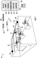
- FIG. 1 shows a schematic illustration of an air particulate detection system 10, according to an embodiment of the present disclosure.
- the air particulate detection system 10 may comprise an aspiration particulate detection system 50, one or more pipe runs 70 fluidly connected to the aspiration detection system 50, and a secondary particulate detector 100 fluidly connected to the aspiration particulate detection system 50 through the one or more pipe runs 70.
- Each of the one or more pipe runs 70 initiate at a first end 72 and terminates at a second end 74.
- the aspiration detection system 50 is fluidly connected to each of the one or more pipe runs 70 at the second ends 74.
- Each of the one or more pipe runs 70 includes one or more sampling points 60 configured to allow air particulates entry into at least one of the one or more pipe runs.
- the sampling points 60 may be an orifice and/or a nozzle in two non-limiting embodiments.
- the aspiration particulate detection system 50 further comprises a blower 52 to transport air particulates from each of the one or more sampling points 60 through the one or more pipe runs 70 to the aspiration particulate detection system 50.
- the blower 52 also transports the air particulates through each of the secondary particulate detectors 74.
- the secondary particulate detector 100 may be located proximate the first end of one of the pipe runs 70 or the secondary particulate detector 100 may be located in the middle of the pipe run 70.
- the secondary particulate detector 100 is located proximate to at least one of the one or more sampling points 60.
- locating the secondary particulate detector 100 proximate to a sampling point 60 reduces detection time by removing transport time.
- Air particulate identification occurs close to the sample point 60 rather than waiting for the air particulate to travel from the sampling point 60 through the pipe run 70 to the aspiration particulate detection system 50. Also advantageously, locating the secondary particulate detector 100 proximate to a sampling point 60 allows for identification of a location 220 of the air particulate. For example, a secondary particulate detector 100 may be located in each detection area 12 of a building and the detection area 12 where smoke arises may be identified by which secondary particulate detector 100 detects smoke.
- the secondary particulate detector 100 is in wireless electronic communication with the aspiration particulate detection system 50 and may be powered by an independent power source (not shown).
- the independent power source may be a battery.
- the secondary particulate detector 100 is located in the same detection area 12 as the aspiration particulate detection system 50 but each may be located in different detection area 12.
- the secondary particulate detector 100 may be located in a first detection area and the aspiration particulate detection system 50 may be located in a second detection area separate from the first detection area.
- noise from the blower 52 may be reduced in the first detection area while maintaining quick particulate identification capability by the secondary particulate detector 100 in the first detection area.
- FIGs. 2 and 3 each show a cross-section illustration of the secondary particulate detector 100.
- the secondary particulate detector 100 may include a laser source 120 configured to generate a laser 130 having a plurality of wavelengths and polarizations.
- the secondary particulate detector 100 may also include a sensor 170 configured to detect at least one of an amount of laser scatter, laser fluorescence or light generated from nonlinear optical effects in response to interaction of the laser 130 and air particulates.
- the secondary particulate detector 100 is configured to transmit at least one of the amount of light scatter and the laser fluorescence to the aspiration particulate detection system 50.
- the secondary particulate detector 100 may also be configured to determine an identity 210 of the air particulate in response to at least one of the amount of light scatter and the laser fluorescence. For example, light scatter and/or laser fluorescence may help identify smoke and combustion materials.
- the secondary particulate detector 100 is configured to transmit the identity 210 of the air particulate to the aspiration particulate detection system 50.
- the aspiration particulate detection system 50 is configured to activate an alarm in response to the identity 210 of the air particulate.
- the alarm may be audible and/or visual.
- the secondary particulate detector 100 may also include a light source 160 configured to generate an ultraviolet light and/or an infrared light.
- the infrared light can be one or more wavelengths in a range of 700 nm to 30,000 nm, 700 nm 4,000 nm or more specifically, 700 nm 1,500nm.
- the ultraviolet light can be in a wavelength range of 25 nm to 480 nm, 160 nm to 480 nm or more specifically 375 nm to 480 nm.
- a detector 170 configured to detect an ultraviolet or infrared signature of an air particulate in response to interaction of the infrared light 162 and the air particulate.
- the secondary particulate detector 100 is configured to reflect light from the light source 160 to the detector 170. A single reflection, as shown in FIG. 3 , increases the path length and improves sensitivity to the air particulates of interest. Multiple passes can be utilized to increase the path length further to improve sensitivity to gases.
- Ultraviolet light may be utilized to identify biomolecules, spores, cells and toxins by looking for laser induced fluorescence. Infrared may be utilized to detect combustion, industrial and toxic particulates that have vibrational resonances in the infrared frequency band. The resonance cause light to be absorbed reducing the transmitted light and changing the signal that the detector 170 observes.
- the secondary particulate detector 100 is configured to transmit the infrared signature to the aspiration particulate detection system 50.
- the secondary particulate detector 100 may also be configured to determine an identity 210 of the air particulate in response to the ultraviolet or infrared signature.
- a location 220, a concentration 230, and/or an identity 210 of the air particulate may be determined by algorithms that process the data collected from sensor 170 in the secondary particulate detector 100.
- the location 220 may depict the detection area 12 where the air particulate was detected and/or where in the detection area 12 the air particulate was detected.
- the air particulate concentration 230 may depict a concentration of the air particulate in the location 220 and/or detection area 12.
- the air particulate concentration 230 may be a particulate concentration at a size.
- data collected by the secondary particulate detector 100 may be compared to a histogram of values.
- the presence of a statistically significant value may initiate an alarm.
- the addition of multiple data points collected over time and from different configurations is used to identify the air particulates.
- a parallel decision making approach based on support vector machine learning process compares the multiple data points to a multidimensional threshold. The result from the threshold is determination of the air particulates' identity 210.
- the secondary particulate detector 100 can be configured to transmit the location 220, concentration 230, and/or identity 210 of the air particulate to the aspiration particulate detection system 50 and/or a user device 300.
- An air particulate concentration 230 of the air particulate is then displayed on a user interface of a user device, an alarm panel and/or a remote visualization tool.
- a user device may include but is not limited to a computing device, such as, for example a desktop computer, a smart phone, a smart watch, a tablet, and/or any similar computing device known to one of skill in the art.
- the use device 300 is in electronic communication with at least one of the secondary particulate detector 100 and the aspiration particulate detection system 50.
- the user device 300 may include a touch screen (not shown), mouse, keyboard, scroll wheel, physical button, or any input mechanism known to one of skill in the art.
- the user device 300 may include a processor 350, memory 352 and communication module 354 as shown in FIG. 1 .
- the processor 350 can be any type or combination of computer processors, such as a microprocessor, microcontroller, digital signal processor, application specific integrated circuit, programmable logic device, and/or field programmable gate array.
- the memory 352 is an example of a non-transitory computer readable storage medium tangibly embodied in the user device 300 including executable instructions stored therein, for instance, as firmware.
- the communication module 354 may implement one or more communication protocols as described in further detail herein. Embodiments herein generate a graphical user interface on the user device 300 through an application 355.
- the graphical user interface may display at least one of the air particulate concentration 230, the location 220 of the air particulate, and the identity 210 of the air particulate.
- the aspiration particulate detection system 50 may be configured to activate an alarm 359 in response to the identity 210 of the air particulate.
- the alarm 359 may be audible and/or visual.
- the alarm 359 may emanate from the user device 300.
- the user device 300 may include an alert device 357 configured to activate the alarm 359. In three non-limiting examples, the alert device 357 may be a vibration motor, audio speaker, and/or display screen.
- FIG. 4 shows a flow diagram illustrating a method 400 of detecting air particulates.
- an air particulate is allowed entry into one or more pipe runs 70 through one or more sampling points 60.
- Each of the one or more pipe runs 70 initiates at a first end 72 and terminates at a second end 74.
- the air particulate is conveyed through the one or more pipe runs 70 using an aspiration particulate detection system 50 fluidly connected each of the one or more pipe runs 70 at the second end 74.
- a blower 52 may be used to convey the air particulate.
- an identity 210 of the air particulate is determined using a secondary particulate detector 100 fluidly connected to the aspiration particulate detection system 50 through the one or more pipe runs 70.
- the method 400 may also include transmitting the identity 210 of the air particulate from the secondary particulate detector 100 to the aspiration particulate detection system 50.
- the method 400 may further include: determining at least one of a location 220 of the air particulate and an air particulate concentration 230.
- the method 400 may also include: displaying at least one of the air particulate concentration 230, the location 220 of the air particulate, and the identity 210 of the air particulate.
- the air particulate concentration 230, the location 220 of the air particulate, and/or the identity 2140 of the air particulate may be displayed on a user device, as described above.
- the method 400 may further include: activating an alarm 359 in response to at least one of the air particulate concentration 230, the location 220 of the air particulate, and the identity 210 of the air particulate.
- the alarm 359 may be audible and/or visual, as described above.
- the alarm 359 may emanate from the user device 300.
- embodiments can be in the form of processor-implemented processes and devices for practicing those processes, such as a processor.
- Embodiments can also be in the form of computer program code containing instructions embodied in tangible media, such as network cloud storage, SD cards, flash drives, floppy diskettes, CD ROMs, hard drives, or any other computer-readable storage medium, wherein, when the computer program code is loaded into and executed by a computer, the computer becomes a device for practicing the embodiments.
- Embodiments can also be in the form of computer program code, for example, whether stored in a storage medium, loaded into and/or executed by a computer, or transmitted over some transmission medium, loaded into and/or executed by a computer, or transmitted over some transmission medium, such as over electrical wiring or cabling, through fiber optics, or via electromagnetic radiation, wherein, when the computer program code is loaded into an executed by a computer, the computer becomes a device for practicing the embodiments.
- the computer program code segments configure the microprocessor to create specific logic circuits.
Landscapes
- Health & Medical Sciences (AREA)
- Chemical & Material Sciences (AREA)
- Life Sciences & Earth Sciences (AREA)
- Biochemistry (AREA)
- Physics & Mathematics (AREA)
- Analytical Chemistry (AREA)
- General Health & Medical Sciences (AREA)
- General Physics & Mathematics (AREA)
- Immunology (AREA)
- Pathology (AREA)
- Dispersion Chemistry (AREA)
- Engineering & Computer Science (AREA)
- Biomedical Technology (AREA)
- Molecular Biology (AREA)
- Investigating Or Analysing Materials By Optical Means (AREA)
Priority Applications (2)
| Application Number | Priority Date | Filing Date | Title |
|---|---|---|---|
| EP17382763.5A EP3483585B1 (fr) | 2017-11-13 | 2017-11-13 | Système de détection de particules d'air |
| US16/185,225 US10690584B2 (en) | 2017-11-13 | 2018-11-09 | Air particulate detection system |
Applications Claiming Priority (1)
| Application Number | Priority Date | Filing Date | Title |
|---|---|---|---|
| EP17382763.5A EP3483585B1 (fr) | 2017-11-13 | 2017-11-13 | Système de détection de particules d'air |
Publications (2)
| Publication Number | Publication Date |
|---|---|
| EP3483585A1 true EP3483585A1 (fr) | 2019-05-15 |
| EP3483585B1 EP3483585B1 (fr) | 2022-06-29 |
Family
ID=60382136
Family Applications (1)
| Application Number | Title | Priority Date | Filing Date |
|---|---|---|---|
| EP17382763.5A Active EP3483585B1 (fr) | 2017-11-13 | 2017-11-13 | Système de détection de particules d'air |
Country Status (2)
| Country | Link |
|---|---|
| US (1) | US10690584B2 (fr) |
| EP (1) | EP3483585B1 (fr) |
Cited By (3)
| Publication number | Priority date | Publication date | Assignee | Title |
|---|---|---|---|---|
| CN112683600A (zh) * | 2020-12-17 | 2021-04-20 | 山东大学 | 一种基于传感器控制的全自动雾水采样器及其使用方法 |
| EP3995806A1 (fr) * | 2020-11-06 | 2022-05-11 | Carrier Corporation | Système de détection de particules et de la qualité de l'air |
| US20230117469A1 (en) * | 2021-10-20 | 2023-04-20 | Wynd Technologies, Inc. | Particulate detection, counting, and identification |
Families Citing this family (4)
| Publication number | Priority date | Publication date | Assignee | Title |
|---|---|---|---|---|
| US10852202B2 (en) * | 2016-11-11 | 2020-12-01 | Kidde Technologies, Inc. | High sensitivity fiber optic based detection |
| EP3828529B1 (fr) | 2019-11-27 | 2025-12-24 | Carrier Corporation | Détecteur de fumée pour système de détecteur de fumée d'aspiration |
| US11474018B2 (en) | 2019-12-05 | 2022-10-18 | Carrier Corporation | Fluorescence enhanced LIDAR based particulate detector |
| US11726035B2 (en) * | 2020-12-11 | 2023-08-15 | Raytheon Technologies Corporation | Terahertz enhanced foreign object debris discrimination for optical particulate sensor |
Citations (4)
| Publication number | Priority date | Publication date | Assignee | Title |
|---|---|---|---|---|
| WO1998046978A1 (fr) * | 1997-04-15 | 1998-10-22 | Phoenix Controls Corporation | Systeme en reseau de mesure de l'air |
| US7242009B1 (en) * | 2005-06-22 | 2007-07-10 | Hach Ultra Analytics, Inc. | Methods and systems for signal processing in particle detection systems |
| US20150022363A1 (en) * | 2013-07-19 | 2015-01-22 | Honeywell International Inc. | Multi-Channel Aspirated Smoke Detector |
| US20170212030A1 (en) * | 2016-01-27 | 2017-07-27 | Fuji Electric Co., Ltd. | Particle analyzing apparatus |
Family Cites Families (16)
| Publication number | Priority date | Publication date | Assignee | Title |
|---|---|---|---|---|
| AUPN965896A0 (en) | 1996-05-03 | 1996-05-30 | Vision Products Pty Ltd | The detection of airborne pollutants |
| AUPQ553800A0 (en) | 2000-02-10 | 2000-03-02 | Cole, Martin Terence | Improvements relating to smoke detectors particularily duct monitored smoke detectors |
| DE10125687B4 (de) | 2001-05-25 | 2005-06-16 | Wagner Alarm- Und Sicherungssysteme Gmbh | Vorrichtung zum Detektieren von Brandherden oder Gasverunreinigungen |
| JP3714926B2 (ja) | 2002-08-22 | 2005-11-09 | ホーチキ株式会社 | サンプリング管式煙検知器 |
| JP4980101B2 (ja) | 2007-03-08 | 2012-07-18 | 能美防災株式会社 | 煙感知器 |
| US8754775B2 (en) | 2009-03-20 | 2014-06-17 | Nest Labs, Inc. | Use of optical reflectance proximity detector for nuisance mitigation in smoke alarms |
| CN201716810U (zh) | 2009-11-30 | 2011-01-19 | 西安博康电子有限公司 | 吸气式双重检测感烟火灾探测系统 |
| CN101727727B (zh) | 2009-11-30 | 2011-06-15 | 西安博康电子有限公司 | 吸气式双重检测感烟火灾探测系统及其报警方法 |
| CN103098107B (zh) | 2011-09-02 | 2016-05-25 | 日本芬翁股份有限公司 | 吸气式烟雾检测系统 |
| US8743366B2 (en) | 2012-08-31 | 2014-06-03 | Fenwal Controls Of Japan, Ltd. | Light emission portion, photoelectric smoke sensor, and suction-type smoke sensing system |
| CN103280057B (zh) | 2013-05-06 | 2016-08-03 | 西安博康电子有限公司 | 一种分布式空气采样烟雾探测系统 |
| CN203250387U (zh) | 2013-05-06 | 2013-10-23 | 西安博康电子有限公司 | 一种分布式空气采样烟雾探测系统 |
| CN203870754U (zh) | 2014-04-28 | 2014-10-08 | 安徽辰安消防科技有限公司 | 一种吸气式烟雾探测系统 |
| GB2531495B (en) | 2014-06-16 | 2017-04-12 | Apollo Fire Detectors Ltd | Smoke detector |
| CN206451328U (zh) | 2017-01-20 | 2017-08-29 | 广东金关安保系统工程有限公司 | 一种吸气式感烟火灾探测器 |
| US10169982B1 (en) * | 2017-07-03 | 2019-01-01 | Honeywell International Inc. | Systems and methods for delaying or activating a blowout device or a purge device in a sampling pipe network of an aspirated smoke detection system |
-
2017
- 2017-11-13 EP EP17382763.5A patent/EP3483585B1/fr active Active
-
2018
- 2018-11-09 US US16/185,225 patent/US10690584B2/en active Active
Patent Citations (4)
| Publication number | Priority date | Publication date | Assignee | Title |
|---|---|---|---|---|
| WO1998046978A1 (fr) * | 1997-04-15 | 1998-10-22 | Phoenix Controls Corporation | Systeme en reseau de mesure de l'air |
| US7242009B1 (en) * | 2005-06-22 | 2007-07-10 | Hach Ultra Analytics, Inc. | Methods and systems for signal processing in particle detection systems |
| US20150022363A1 (en) * | 2013-07-19 | 2015-01-22 | Honeywell International Inc. | Multi-Channel Aspirated Smoke Detector |
| US20170212030A1 (en) * | 2016-01-27 | 2017-07-27 | Fuji Electric Co., Ltd. | Particle analyzing apparatus |
Cited By (5)
| Publication number | Priority date | Publication date | Assignee | Title |
|---|---|---|---|---|
| EP3995806A1 (fr) * | 2020-11-06 | 2022-05-11 | Carrier Corporation | Système de détection de particules et de la qualité de l'air |
| US12281974B2 (en) | 2020-11-06 | 2025-04-22 | Carrier Corporation | Air quality and particulate detection system |
| CN112683600A (zh) * | 2020-12-17 | 2021-04-20 | 山东大学 | 一种基于传感器控制的全自动雾水采样器及其使用方法 |
| US20230117469A1 (en) * | 2021-10-20 | 2023-04-20 | Wynd Technologies, Inc. | Particulate detection, counting, and identification |
| US12306104B2 (en) * | 2021-10-20 | 2025-05-20 | Wynd Technologies, Inc. | Particulate detection, counting, and identification |
Also Published As
| Publication number | Publication date |
|---|---|
| EP3483585B1 (fr) | 2022-06-29 |
| US20190145883A1 (en) | 2019-05-16 |
| US10690584B2 (en) | 2020-06-23 |
Similar Documents
| Publication | Publication Date | Title |
|---|---|---|
| US10690584B2 (en) | Air particulate detection system | |
| US8098166B2 (en) | Variable air speed aspirating smoke detector | |
| US10037665B2 (en) | Chamber-less smoke sensor | |
| TWI777081B (zh) | 多光譜感測器、及使用其的偵測器和方法 | |
| US10685545B2 (en) | Wide-area chamberless point smoke detector | |
| US10186135B2 (en) | Wearable chemical threat detector | |
| US20150059583A1 (en) | Fume extraction | |
| US11906415B1 (en) | Pollutant sensor device, system and method | |
| CN103268644A (zh) | 通信设备巡检系统 | |
| US12281974B2 (en) | Air quality and particulate detection system | |
| US20200256789A1 (en) | Detection of Compounds in Material Samples Utilizing a Transformation and Subsequent Decomposition | |
| US20240396609A1 (en) | System and method of detecting environmental changes using wireless sensing | |
| JP6662621B2 (ja) | 煙検出装置 | |
| CN115294715A (zh) | 一种火焰识别方法和装置 | |
| EP4451244A1 (fr) | Détecteur de fumée par aspiration, procédé et dispositif de surveillance d'un détecteur de fumée par aspiration | |
| US11790745B2 (en) | Fire detection with data transmission | |
| CN119785512A (zh) | 感烟探测装置、方法、设备、存储介质及程序产品 | |
| CN115452040A (zh) | 一种根据振动模型进行电缆附着物的识别装置 |
Legal Events
| Date | Code | Title | Description |
|---|---|---|---|
| PUAI | Public reference made under article 153(3) epc to a published international application that has entered the european phase |
Free format text: ORIGINAL CODE: 0009012 |
|
| STAA | Information on the status of an ep patent application or granted ep patent |
Free format text: STATUS: THE APPLICATION HAS BEEN PUBLISHED |
|
| AK | Designated contracting states |
Kind code of ref document: A1 Designated state(s): AL AT BE BG CH CY CZ DE DK EE ES FI FR GB GR HR HU IE IS IT LI LT LU LV MC MK MT NL NO PL PT RO RS SE SI SK SM TR |
|
| AX | Request for extension of the european patent |
Extension state: BA ME |
|
| STAA | Information on the status of an ep patent application or granted ep patent |
Free format text: STATUS: REQUEST FOR EXAMINATION WAS MADE |
|
| 17P | Request for examination filed |
Effective date: 20191115 |
|
| RBV | Designated contracting states (corrected) |
Designated state(s): AL AT BE BG CH CY CZ DE DK EE ES FI FR GB GR HR HU IE IS IT LI LT LU LV MC MK MT NL NO PL PT RO RS SE SI SK SM TR |
|
| STAA | Information on the status of an ep patent application or granted ep patent |
Free format text: STATUS: EXAMINATION IS IN PROGRESS |
|
| 17Q | First examination report despatched |
Effective date: 20200813 |
|
| GRAP | Despatch of communication of intention to grant a patent |
Free format text: ORIGINAL CODE: EPIDOSNIGR1 |
|
| STAA | Information on the status of an ep patent application or granted ep patent |
Free format text: STATUS: GRANT OF PATENT IS INTENDED |
|
| RIC1 | Information provided on ipc code assigned before grant |
Ipc: G01N 15/06 20060101ALN20220105BHEP Ipc: G01N 1/26 20060101ALI20220105BHEP Ipc: G01N 1/22 20060101AFI20220105BHEP |
|
| INTG | Intention to grant announced |
Effective date: 20220126 |
|
| RIC1 | Information provided on ipc code assigned before grant |
Ipc: G01N 15/06 20060101ALN20220114BHEP Ipc: G01N 1/26 20060101ALI20220114BHEP Ipc: G01N 1/22 20060101AFI20220114BHEP |
|
| GRAS | Grant fee paid |
Free format text: ORIGINAL CODE: EPIDOSNIGR3 |
|
| GRAA | (expected) grant |
Free format text: ORIGINAL CODE: 0009210 |
|
| STAA | Information on the status of an ep patent application or granted ep patent |
Free format text: STATUS: THE PATENT HAS BEEN GRANTED |
|
| AK | Designated contracting states |
Kind code of ref document: B1 Designated state(s): AL AT BE BG CH CY CZ DE DK EE ES FI FR GB GR HR HU IE IS IT LI LT LU LV MC MK MT NL NO PL PT RO RS SE SI SK SM TR |
|
| REG | Reference to a national code |
Ref country code: CH Ref legal event code: EP |
|
| REG | Reference to a national code |
Ref country code: AT Ref legal event code: REF Ref document number: 1501655 Country of ref document: AT Kind code of ref document: T Effective date: 20220715 |
|
| REG | Reference to a national code |
Ref country code: IE Ref legal event code: FG4D |
|
| REG | Reference to a national code |
Ref country code: DE Ref legal event code: R096 Ref document number: 602017058967 Country of ref document: DE |
|
| REG | Reference to a national code |
Ref country code: LT Ref legal event code: MG9D |
|
| PG25 | Lapsed in a contracting state [announced via postgrant information from national office to epo] |
Ref country code: SE Free format text: LAPSE BECAUSE OF FAILURE TO SUBMIT A TRANSLATION OF THE DESCRIPTION OR TO PAY THE FEE WITHIN THE PRESCRIBED TIME-LIMIT Effective date: 20220629 Ref country code: NO Free format text: LAPSE BECAUSE OF FAILURE TO SUBMIT A TRANSLATION OF THE DESCRIPTION OR TO PAY THE FEE WITHIN THE PRESCRIBED TIME-LIMIT Effective date: 20220929 Ref country code: LT Free format text: LAPSE BECAUSE OF FAILURE TO SUBMIT A TRANSLATION OF THE DESCRIPTION OR TO PAY THE FEE WITHIN THE PRESCRIBED TIME-LIMIT Effective date: 20220629 Ref country code: HR Free format text: LAPSE BECAUSE OF FAILURE TO SUBMIT A TRANSLATION OF THE DESCRIPTION OR TO PAY THE FEE WITHIN THE PRESCRIBED TIME-LIMIT Effective date: 20220629 Ref country code: GR Free format text: LAPSE BECAUSE OF FAILURE TO SUBMIT A TRANSLATION OF THE DESCRIPTION OR TO PAY THE FEE WITHIN THE PRESCRIBED TIME-LIMIT Effective date: 20220930 Ref country code: FI Free format text: LAPSE BECAUSE OF FAILURE TO SUBMIT A TRANSLATION OF THE DESCRIPTION OR TO PAY THE FEE WITHIN THE PRESCRIBED TIME-LIMIT Effective date: 20220629 Ref country code: BG Free format text: LAPSE BECAUSE OF FAILURE TO SUBMIT A TRANSLATION OF THE DESCRIPTION OR TO PAY THE FEE WITHIN THE PRESCRIBED TIME-LIMIT Effective date: 20220929 |
|
| REG | Reference to a national code |
Ref country code: NL Ref legal event code: MP Effective date: 20220629 |
|
| REG | Reference to a national code |
Ref country code: AT Ref legal event code: MK05 Ref document number: 1501655 Country of ref document: AT Kind code of ref document: T Effective date: 20220629 |
|
| PG25 | Lapsed in a contracting state [announced via postgrant information from national office to epo] |
Ref country code: RS Free format text: LAPSE BECAUSE OF FAILURE TO SUBMIT A TRANSLATION OF THE DESCRIPTION OR TO PAY THE FEE WITHIN THE PRESCRIBED TIME-LIMIT Effective date: 20220629 Ref country code: LV Free format text: LAPSE BECAUSE OF FAILURE TO SUBMIT A TRANSLATION OF THE DESCRIPTION OR TO PAY THE FEE WITHIN THE PRESCRIBED TIME-LIMIT Effective date: 20220629 |
|
| PG25 | Lapsed in a contracting state [announced via postgrant information from national office to epo] |
Ref country code: NL Free format text: LAPSE BECAUSE OF FAILURE TO SUBMIT A TRANSLATION OF THE DESCRIPTION OR TO PAY THE FEE WITHIN THE PRESCRIBED TIME-LIMIT Effective date: 20220629 |
|
| PG25 | Lapsed in a contracting state [announced via postgrant information from national office to epo] |
Ref country code: SM Free format text: LAPSE BECAUSE OF FAILURE TO SUBMIT A TRANSLATION OF THE DESCRIPTION OR TO PAY THE FEE WITHIN THE PRESCRIBED TIME-LIMIT Effective date: 20220629 Ref country code: SK Free format text: LAPSE BECAUSE OF FAILURE TO SUBMIT A TRANSLATION OF THE DESCRIPTION OR TO PAY THE FEE WITHIN THE PRESCRIBED TIME-LIMIT Effective date: 20220629 Ref country code: RO Free format text: LAPSE BECAUSE OF FAILURE TO SUBMIT A TRANSLATION OF THE DESCRIPTION OR TO PAY THE FEE WITHIN THE PRESCRIBED TIME-LIMIT Effective date: 20220629 Ref country code: PT Free format text: LAPSE BECAUSE OF FAILURE TO SUBMIT A TRANSLATION OF THE DESCRIPTION OR TO PAY THE FEE WITHIN THE PRESCRIBED TIME-LIMIT Effective date: 20221031 Ref country code: ES Free format text: LAPSE BECAUSE OF FAILURE TO SUBMIT A TRANSLATION OF THE DESCRIPTION OR TO PAY THE FEE WITHIN THE PRESCRIBED TIME-LIMIT Effective date: 20220629 Ref country code: EE Free format text: LAPSE BECAUSE OF FAILURE TO SUBMIT A TRANSLATION OF THE DESCRIPTION OR TO PAY THE FEE WITHIN THE PRESCRIBED TIME-LIMIT Effective date: 20220629 Ref country code: AT Free format text: LAPSE BECAUSE OF FAILURE TO SUBMIT A TRANSLATION OF THE DESCRIPTION OR TO PAY THE FEE WITHIN THE PRESCRIBED TIME-LIMIT Effective date: 20220629 |
|
| PG25 | Lapsed in a contracting state [announced via postgrant information from national office to epo] |
Ref country code: PL Free format text: LAPSE BECAUSE OF FAILURE TO SUBMIT A TRANSLATION OF THE DESCRIPTION OR TO PAY THE FEE WITHIN THE PRESCRIBED TIME-LIMIT Effective date: 20220629 Ref country code: IS Free format text: LAPSE BECAUSE OF FAILURE TO SUBMIT A TRANSLATION OF THE DESCRIPTION OR TO PAY THE FEE WITHIN THE PRESCRIBED TIME-LIMIT Effective date: 20221029 |
|
| REG | Reference to a national code |
Ref country code: DE Ref legal event code: R097 Ref document number: 602017058967 Country of ref document: DE |
|
| PG25 | Lapsed in a contracting state [announced via postgrant information from national office to epo] |
Ref country code: AL Free format text: LAPSE BECAUSE OF FAILURE TO SUBMIT A TRANSLATION OF THE DESCRIPTION OR TO PAY THE FEE WITHIN THE PRESCRIBED TIME-LIMIT Effective date: 20220629 |
|
| PG25 | Lapsed in a contracting state [announced via postgrant information from national office to epo] |
Ref country code: DK Free format text: LAPSE BECAUSE OF FAILURE TO SUBMIT A TRANSLATION OF THE DESCRIPTION OR TO PAY THE FEE WITHIN THE PRESCRIBED TIME-LIMIT Effective date: 20220629 Ref country code: CZ Free format text: LAPSE BECAUSE OF FAILURE TO SUBMIT A TRANSLATION OF THE DESCRIPTION OR TO PAY THE FEE WITHIN THE PRESCRIBED TIME-LIMIT Effective date: 20220629 |
|
| PLBE | No opposition filed within time limit |
Free format text: ORIGINAL CODE: 0009261 |
|
| STAA | Information on the status of an ep patent application or granted ep patent |
Free format text: STATUS: NO OPPOSITION FILED WITHIN TIME LIMIT |
|
| 26N | No opposition filed |
Effective date: 20230330 |
|
| PG25 | Lapsed in a contracting state [announced via postgrant information from national office to epo] |
Ref country code: MC Free format text: LAPSE BECAUSE OF FAILURE TO SUBMIT A TRANSLATION OF THE DESCRIPTION OR TO PAY THE FEE WITHIN THE PRESCRIBED TIME-LIMIT Effective date: 20220629 |
|
| REG | Reference to a national code |
Ref country code: CH Ref legal event code: PL |
|
| REG | Reference to a national code |
Ref country code: BE Ref legal event code: MM Effective date: 20221130 |
|
| PG25 | Lapsed in a contracting state [announced via postgrant information from national office to epo] |
Ref country code: LI Free format text: LAPSE BECAUSE OF NON-PAYMENT OF DUE FEES Effective date: 20221130 Ref country code: CH Free format text: LAPSE BECAUSE OF NON-PAYMENT OF DUE FEES Effective date: 20221130 |
|
| PG25 | Lapsed in a contracting state [announced via postgrant information from national office to epo] |
Ref country code: SI Free format text: LAPSE BECAUSE OF FAILURE TO SUBMIT A TRANSLATION OF THE DESCRIPTION OR TO PAY THE FEE WITHIN THE PRESCRIBED TIME-LIMIT Effective date: 20220629 Ref country code: LU Free format text: LAPSE BECAUSE OF NON-PAYMENT OF DUE FEES Effective date: 20221113 |
|
| PG25 | Lapsed in a contracting state [announced via postgrant information from national office to epo] |
Ref country code: IE Free format text: LAPSE BECAUSE OF NON-PAYMENT OF DUE FEES Effective date: 20221113 |
|
| PG25 | Lapsed in a contracting state [announced via postgrant information from national office to epo] |
Ref country code: BE Free format text: LAPSE BECAUSE OF NON-PAYMENT OF DUE FEES Effective date: 20221130 |
|
| PG25 | Lapsed in a contracting state [announced via postgrant information from national office to epo] |
Ref country code: IT Free format text: LAPSE BECAUSE OF FAILURE TO SUBMIT A TRANSLATION OF THE DESCRIPTION OR TO PAY THE FEE WITHIN THE PRESCRIBED TIME-LIMIT Effective date: 20220629 |
|
| PG25 | Lapsed in a contracting state [announced via postgrant information from national office to epo] |
Ref country code: HU Free format text: LAPSE BECAUSE OF FAILURE TO SUBMIT A TRANSLATION OF THE DESCRIPTION OR TO PAY THE FEE WITHIN THE PRESCRIBED TIME-LIMIT; INVALID AB INITIO Effective date: 20171113 |
|
| PG25 | Lapsed in a contracting state [announced via postgrant information from national office to epo] |
Ref country code: CY Free format text: LAPSE BECAUSE OF FAILURE TO SUBMIT A TRANSLATION OF THE DESCRIPTION OR TO PAY THE FEE WITHIN THE PRESCRIBED TIME-LIMIT Effective date: 20220629 |
|
| PG25 | Lapsed in a contracting state [announced via postgrant information from national office to epo] |
Ref country code: MK Free format text: LAPSE BECAUSE OF FAILURE TO SUBMIT A TRANSLATION OF THE DESCRIPTION OR TO PAY THE FEE WITHIN THE PRESCRIBED TIME-LIMIT Effective date: 20220629 |
|
| PG25 | Lapsed in a contracting state [announced via postgrant information from national office to epo] |
Ref country code: MT Free format text: LAPSE BECAUSE OF FAILURE TO SUBMIT A TRANSLATION OF THE DESCRIPTION OR TO PAY THE FEE WITHIN THE PRESCRIBED TIME-LIMIT Effective date: 20220629 |
|
| PG25 | Lapsed in a contracting state [announced via postgrant information from national office to epo] |
Ref country code: BG Free format text: LAPSE BECAUSE OF FAILURE TO SUBMIT A TRANSLATION OF THE DESCRIPTION OR TO PAY THE FEE WITHIN THE PRESCRIBED TIME-LIMIT Effective date: 20220629 |
|
| PG25 | Lapsed in a contracting state [announced via postgrant information from national office to epo] |
Ref country code: BG Free format text: LAPSE BECAUSE OF FAILURE TO SUBMIT A TRANSLATION OF THE DESCRIPTION OR TO PAY THE FEE WITHIN THE PRESCRIBED TIME-LIMIT Effective date: 20220629 |
|
| PG25 | Lapsed in a contracting state [announced via postgrant information from national office to epo] |
Ref country code: TR Free format text: LAPSE BECAUSE OF FAILURE TO SUBMIT A TRANSLATION OF THE DESCRIPTION OR TO PAY THE FEE WITHIN THE PRESCRIBED TIME-LIMIT Effective date: 20220629 |
|
| PGFP | Annual fee paid to national office [announced via postgrant information from national office to epo] |
Ref country code: DE Payment date: 20251022 Year of fee payment: 9 |
|
| PGFP | Annual fee paid to national office [announced via postgrant information from national office to epo] |
Ref country code: GB Payment date: 20251023 Year of fee payment: 9 |
|
| PGFP | Annual fee paid to national office [announced via postgrant information from national office to epo] |
Ref country code: FR Payment date: 20251022 Year of fee payment: 9 |