EP3483633A1 - Verfahren zur reduzierung der anzahl von auszulesenen signalen in einem detektor - Google Patents
Verfahren zur reduzierung der anzahl von auszulesenen signalen in einem detektor Download PDFInfo
- Publication number
- EP3483633A1 EP3483633A1 EP17382769.2A EP17382769A EP3483633A1 EP 3483633 A1 EP3483633 A1 EP 3483633A1 EP 17382769 A EP17382769 A EP 17382769A EP 3483633 A1 EP3483633 A1 EP 3483633A1
- Authority
- EP
- European Patent Office
- Prior art keywords
- detector
- photosensor
- signals
- center
- read out
- Prior art date
- Legal status (The legal status is an assumption and is not a legal conclusion. Google has not performed a legal analysis and makes no representation as to the accuracy of the status listed.)
- Withdrawn
Links
Images


Classifications
-
- G—PHYSICS
- G01—MEASURING; TESTING
- G01T—MEASUREMENT OF NUCLEAR OR X-RADIATION
- G01T1/00—Measuring X-radiation, gamma radiation, corpuscular radiation, or cosmic radiation
- G01T1/16—Measuring radiation intensity
- G01T1/24—Measuring radiation intensity with semiconductor detectors
- G01T1/247—Detector read-out circuitry
-
- G—PHYSICS
- G01—MEASURING; TESTING
- G01T—MEASUREMENT OF NUCLEAR OR X-RADIATION
- G01T1/00—Measuring X-radiation, gamma radiation, corpuscular radiation, or cosmic radiation
- G01T1/16—Measuring radiation intensity
- G01T1/20—Measuring radiation intensity with scintillation detectors
- G01T1/208—Circuits specially adapted for scintillation detectors, e.g. for the photo-multiplier section
-
- G—PHYSICS
- G01—MEASURING; TESTING
- G01T—MEASUREMENT OF NUCLEAR OR X-RADIATION
- G01T1/00—Measuring X-radiation, gamma radiation, corpuscular radiation, or cosmic radiation
- G01T1/16—Measuring radiation intensity
- G01T1/20—Measuring radiation intensity with scintillation detectors
- G01T1/2018—Scintillation-photodiode combinations
- G01T1/20184—Detector read-out circuitry, e.g. for clearing of traps, compensating for traps or compensating for direct hits
-
- H—ELECTRICITY
- H10—SEMICONDUCTOR DEVICES; ELECTRIC SOLID-STATE DEVICES NOT OTHERWISE PROVIDED FOR
- H10F—INORGANIC SEMICONDUCTOR DEVICES SENSITIVE TO INFRARED RADIATION, LIGHT, ELECTROMAGNETIC RADIATION OF SHORTER WAVELENGTH OR CORPUSCULAR RADIATION
- H10F30/00—Individual radiation-sensitive semiconductor devices in which radiation controls the flow of current through the devices, e.g. photodetectors
- H10F30/301—Individual radiation-sensitive semiconductor devices in which radiation controls the flow of current through the devices, e.g. photodetectors the devices being sensitive to very short wavelength, e.g. being sensitive to X-rays, gamma-rays or corpuscular radiation
-
- H—ELECTRICITY
- H10—SEMICONDUCTOR DEVICES; ELECTRIC SOLID-STATE DEVICES NOT OTHERWISE PROVIDED FOR
- H10F—INORGANIC SEMICONDUCTOR DEVICES SENSITIVE TO INFRARED RADIATION, LIGHT, ELECTROMAGNETIC RADIATION OF SHORTER WAVELENGTH OR CORPUSCULAR RADIATION
- H10F39/00—Integrated devices, or assemblies of multiple devices, comprising at least one element covered by group H10F30/00, e.g. radiation detectors comprising photodiode arrays
- H10F39/10—Integrated devices
- H10F39/12—Image sensors
- H10F39/18—Complementary metal-oxide-semiconductor [CMOS] image sensors; Photodiode array image sensors
- H10F39/189—X-ray, gamma-ray or corpuscular radiation imagers
- H10F39/1898—Indirect radiation image sensors, e.g. using luminescent members
Definitions
- Nuclear medicine techniques such as PET or SPECT provide quantitative functional tomographic information on the metabolic and physiological processes that take place in the body through the spatial distribution of a tracer that has been supplied to the patient.
- the tracer is a molecule from which some of its atoms have been replaced by radioactive isotopes and once incorporated into the organism the metabolic processes move it to the area of interest.
- a nuclear medicine device such as a PET scanner
- the different parameters are interdependent and a compromise has to be found among them for a good image quality.
- the best approach is to read out every single element of the photosensor array (n ⁇ n, n 2 signals to be considered by the data acquisition system), but this typically implies digitizing a huge number of signals.
- This array could be, a position sensitive photomultiplier tube (PSPMT) or a Silicon Photomultiplier (SiPM) matrix, to name but a few.
- Novel techniques have lately been used to reduce the number of channels to be digitized.
- One of the oldest approaches is the so-called Anger logic where all photosensor signals are combined using a resistor network and reduced to only 4. This approach can hardly provide information on the photon depth of interaction within the scintillation volume (monolithic blocks), except of a modification of the resistor network.
- An improved method with respect to the Anger logic is to digitize every row and column of the photosensor array. This means digitizing a number of channels of 2 ⁇ n ( Figure 5 of the present application). This approach has shown good results both using crystal arrays and especially with monolithic blocks since it allows characterization of the light distribution.
- Patent US6747263 by Popov describes a resistor network with the ability to isolate each photosensor output when injected into the corresponding row and column simultaneously.
- Proffit uses a similar approach but exchanging the resistors by diodes in order to be able to suppress certain noise present in former photosensors made out of solid-state technology (SiPM).
- SiPM solid-state technology
- the performance of the 2 ⁇ n approach is very similar to the n ⁇ n approach, since further information is redundant.
- Characterization means determining the centroid and the depth of interaction (in monolithic blocks) of the impinging photon ( A. Gonzalez-Montoro, et al., IEEE Trans. Radiation Plasma Medical Sci., 1, pp. 229, 2017 ; A.J. Gonzalez, et al., IEEE Trans. Nucl. Sci., 63, pp. 2471, 2016 .
- the present invention provides a method that allows to take into account the radiation received by the detector edges -laterals and corners, and especially the corners - and not only the detector center. Thanks to the use of the whole crystal volume as useful data the quality of the image obtained is improved.
- the present invention provides a better result at the detector edges than the methods known so far when using the same number of signals.
- the present invention keeps a good detection performance, especially at the crystal edges, by significantly reducing the number of signals to be digitized. In the particular case of using monolithic crystals this is obtained by better characterizing the light distribution at those edges.
- the detector block, or detector module, used according to the present invention has the capability to resolve events at the crystal edge, using a particular readout scheme with high performance.
- a detector includes a photosensor as one of its components, in this application, an action carried out on the photosensor is sometimes referred to as an action or operation carried out on the detector. Both are to be understood as equivalent because said action on the photosensor has the same consequences on the detector.
- the present invention refers to a method to reduce the number of signals to be read out in a detector, preferably, a radiation detector, characterized in that it comprises using a lower granularity at the photosensor center than at the photosensor corners, or lower than at the photosensor edges (corners and laterals) by means of a granularity degree at the photosensor that is edge dependent. This means that there is an edge dependent granularity degree at the photosensor, or, there is a granularity gradient.
- the method to reduce the number of signals to be read out in a detector characterized in that it comprises using a lower granularity at least at the photosensor center than at the photosensor edges obtaining a granularity degree at the photosensor that is edge dependent.
- the granularity at the detector corners can be higher than at any other detector zone.
- Edge dependent means using a higher granularity at the detector corners and laterals than at the detector center, or at least at the detector corners, thus reducing the number of signals to be transmitted from the photosensor array to the readout electronics by the photosensor elements.
- more specific embodiments comprise to join the signals at the detector center in groups of at least two.
- additional specific embodiments comprise to join the signals at the detector center, and at the detector laterals in groups of at least two.
- the number of signals to be read out can be reduced by joining signals:
- the number of signals to be read out is reduced by joining the signals in groups of at least two.
- additional specific embodiments comprise to join the signals at the detector center, and at the detector laterals and corners in groups of at least two.
- each pixel or element of the photosensor array in the radiation detector is connected to a readout channel, but according to the first alternative of the present invention, pixels from certain number of photosensor elements are connected to a single readout channel, reducing in this way the number of readout channels to be processed.
- the number of signals to be read out is reduced by merging (joining) the signals coming from the photosensor elements located at certain zones of the photosensor array, into groups of at least two signals, for their further processing in the reconstruction process of photon impact determination and, in some cases, keeping the original signals from the remaining photosensor zones.
- Using higher granularity at the detector corners and detector laterals than at the detector center also means in a particular case, providing information for each photosensor element for which the signals at the corners are kept, but those signals coming from the photosensor elements located at the laterals and at the center of the photosensor array are merged in groups of at least two.
- the reduced readout, the number of signals is reduced by merging the signals from the photosensor elements located at the photosensor laterals in the direction perpendicular to the detector block center, and merging the signals from the photosensor elements located at the center block (see Figure 3 ).
- the invention also considers an embodiment reducing the number of signals but again keeping a good sampling of the scintillation light in monolithic crystals.
- the number of total photosensor elements is 144.
- this example could be extended to smaller and also larger number of elements.
- this approach could also be put into practice by using non-regular elements (different shapedphotosensor elements). This is a reduction in signals larger than 50%.
- This second alternative comprises reducing the number of signals by using different photosensor elements, wherein different means that they have different sizes, or different geometry, or a combination of both.
- the number of signals to be read out is reduced by using different photosensor elements at the center of the photosensor with regard to the remaining photosensor zones.
- photosensor elements of different sizes within the radiation detector means that they are larger at the center than at the remaining zones of the detector ( Figure 4 ).
- more specific embodiments comprise using smaller photosensor elements at the detector corners than at the detector center and detector laterals.
- the number of signals to be read out is reduced by using smaller photosensor elements at the detector corners than at the detector center and detector laterals.
- additional specific embodiments comprise using smaller photosensor elements at the detector corners, larger photosensor elements at the detector laterals and even larger photosensor elements at the detector center.
- the number of signals to be transmitted from the photosensor array to the readout electronics by the photosensor elements is reduced by using a photosensor array with photosensor elements of different sizes in a matrix configuration.
- the different sizes mean smaller sizes at least at the corners the edges (laterals and corners) and larger at the center of the photosensor active area.
- a third alternative of the method comprises carrying out any of the two alternatives above and further applying a projection readout by summing all the signals for each row and all the signals for each column giving rise to an additional reduction of the number of signals to be processed by the readout electronics of the detector. If the first alternative is followed, multiple original rows (or columns) would be summed to one end point ( Figure 6 ). In the case of applying the third alternative to the second one, the wider photosensor elements at the center contribute to one end point ( Figure 7 ).
- This third alternative comprises the operation called "projection", this is summing the signals of each row and each column of the photosensor array, which have previously undergone the operation of one of the first or second alternatives explained above, i.e., the number of signals has previously been reduced according to the first, or of the second method alternative.
- An embodiment of the invention referred to the third alternative applied to the first one is for instance considering the case of a photosensor array with identical elements and pitch (center to center distance). This embodiment will consider whatever the particular passive components are used (diodes, resistors, capacitors, combinations of those, etc). Such an embodiment would keep the edge sampling of the photosensor elements size. For instance, in a 12 ⁇ 12 array, the 2 rows (and columns) at the edges will be normally read, but the 8 central ones will merged into 4 readout signals. Therefore, the number of signals to digitize reduces from 24 (2 ⁇ n) to only 16 (8 rows plus 8 columns). This is approximately a 30% reduction in the number of signals.
- the projection readout can be applied to any one of the specific additional embodiments to the first or to the second alternatives as explained above. It also can apply to the second alternative wherein photosensor elements of different geometry - shape - are used.
- the projection readout can also be applied to the additional particular embodiments of the method wherein the first and the second alternative are combined as mentioned above.
- the application of the projection readout by summing all the signals for each row and all the signals for each column can be carried out previous to the joining of signals defined above in the first alternative.
- the detector can be a gamma ray detector that comprises a scintillation block and a photosensor array.
- the scintillation block can be a monolithic crystal.
- the monolithic crystal can undergo any type and surface treatments.
- the scintillation block can also be an array of pixelated crystals.
- the invention also has as an object the use of the method defined above in nuclear medicine imaging techniques, more particularly in the process of reconstructing the impinging position of the gamma radiation emitted by a radiation source and measured by a nuclear imaging device.
- the present invention also refers to a process for the reconstruction of the radiation impact within the detector, particularly data obtained by a nuclear medicine imaging device, said process comprises carrying out the method to reduce the number of signals defined above.
- the process for reconstruction of the radiation, more particularly, gamma ray, impact determination comprises:
- Reducing the number of signals to be read out obtaining a granularity degree at the photosensor, that is edge dependent can be carried out:
- the present invention also refers to a detector module, more particularly a detector module for a nuclear medicine imaging device, to carry out the method, or the process, defined above.
- detector module More particular embodiments of the detector module are defined by the dependent claims at the end of the description.
- the detector module can comprise photosensor elements with a larger active area at the center of the photosensor and smaller active area and the corners, or at the corners and laterals. This feature results in a higher granularity at the detector corners, or at the corners and laterals, than at the detector center.
- the detector module can comprise a photosensor array wherein photosensor elements from certain zones of the array are connected in - or merged into - groups giving rise to a reduced number of signals, what will be appropriate for carrying out the method of the invention according to the first alternative above, or, in another embodiment, the detector module can comprise photosensor elements of different sizes, what will be appropriate for carrying out the method of the invention according to the second alternative above.
- the third alternative of the method defined above can be carried out with a detector module appropriate for carrying out the method as per the first or second alternative, as defined in the preceding paragraph, that further comprises a readout electronics with capability of projecting the photosensor elements onto rows and columns carrying out a reduction readout.
- a detector module appropriate for carrying out the method as per the first or second alternative, as defined in the preceding paragraph, that further comprises a readout electronics with capability of projecting the photosensor elements onto rows and columns carrying out a reduction readout.
- Detector module for carrying out the first alternative of the method above:
- the larger active area at the center is obtained by summing the active area of two, or more, photosensor elements.
- the detector module comprises a photosensor array wherein photosensor elements located at the photosensor array center are merged into groups of at least two, and photosensor elements located at the photosensor array corners and laterals are not merged.
- the detector module comprises a photosensor array wherein photosensor elements located at the photosensor array center are merged into groups of at least two, photosensor elements located at the photosensor array corners are not merged and those located at the laterals are merged in a smaller degree than at the center.
- the detector module comprises a photosensor array wherein photosensor elements located at the photosensor array center are merged into groups of at least two, photosensor elements located at the photosensor array corners and laterals are merged in a smaller degree than at the center.
- the larger active area at the center is obtained by using photosensor elements of different sizes within the photosensor array.
- the elements of the photosensor array are larger at the center area, and smaller at the corners and laterals.
- the elements of the photosensor array can also be larger at the center area, smaller at the laterals than at the center and even smaller at the corners.
- the detector module can be a detector module appropriate for carrying out the first alternative of the method, or the second alternative of the method, and further comprising a readout electronics with capability of projecting the photosensor elements onto rows and columns carrying out a reduction readout.
- the detector module can comprise a readout electronics that provides information for each row and column of the photosensor array (third alternative of the method explained above as applied to the first main alternative), where the edge row and columns are kept with the ideal, or maximal granularity, but those rows and columns towards the center are merged, for instance 2 to 1, depending on the number of signals.
- the elements at the center of the photosensor array are connected at least in pairs to a readout channel (row and column pairs), whereas the photosensor elements at the laterals and corners of the photosensor array are connected minimum to a readout channel.
- a readout channel row and column pairs
- the photosensor elements at the laterals and corners of the photosensor array are connected minimum to a readout channel.
- the detector module comprises a photosensor array wherein the photosensor elements (row and columns) located at the photosensor array corners are not merged, photosensor elements located at the photosensor laterals are merged (into groups of at least two) in the direction perpendicular to the center block, and photosensor elements located at the center block are merged in both directions
- the detector comprises a photosensor with photosensor elements of different sizes in a matrix configuration.
- the different sizes mean smaller sizes at the edges (at the corners, or at the laterals and corners) and larger at the center of the photosensor array. This alternative will satisfy small sampling at the edges but larger at the center.
- different size photosensors could also be used (third alternative applied on the second one) by using photosensor elements of 3 ⁇ 3 mm 2 at the edges, 2 on each edge with 4 mm pitch, and 4 rows and columns of 6 ⁇ 6 mm 2 active area photosensor elements at the center with about 8 mm pitch.
- the photosensor could also have 2 elements at each side of 4 ⁇ 4 mm 2 with a pitch of ideally 4 mm and elements at the center with 8 ⁇ 8 mm 2 with pitch of 8 mm.
- the final number of signals provided by the readout electronics when enabling the projection reduction readout (third alternative applied to the first one) can be mathematically found as follows:
- T (P+R)/2
- P the maximum number of signals to be processed (24 for an array of 12 ⁇ 12 elements, or 32 for an array of 16 ⁇ 16)
- crystal arrays If a crystal array is used instead of a monolithic crystal, the crystal array is coupled to a photosensor array and the reduction readout is used, it is also possible to resolve well all crystal pixels without significant performance degradation. Only at the detector block center, a higher compression of the crystal pixels is observed due to the new larger pitch size.
- a projection readout of identical photosensor elements but with larger pitch (either using larger photosensor elements or larger pitch) to cover the same active area but resulting in a reduced number of signals, will not produce successful results. Reducing the number of elements, keeping constant the active area, means increasing the distance from center to center photosensor and, therefore, the edges will suffer from poor resolution (larger sampling binning size).
- Figure 9 An example of this realization is shown in Figure 9 , right panel. In this particular panel an 8 ⁇ 8 SiPM array with about 6 ⁇ 6 mm photosensors is used, and a projection readout applied (8 + 8 signals). Comparing with the left panel, that uses the third alternative applied to the first one, projection readout of merging signals, also resulting on 8 + 8 final signals, allows one to resolve impacts at the very edge of the crystal, in contrast to the right panel that misses those signals.
- the detector can be a gamma ray detector that comprises a scintillation block and a photosensor array.
- the detector can be a gamma ray detector that comprises a pixelated crystal or crystal array and a photosensor array.
- the crystal array may have any pixel size, height, and may have undergone any treatment.
- the present invention permits to properly characterize the scintillation light distribution in detector blocks for gamma ray imaging, using monolithic scintillation crystals, reducing the number of total signals.
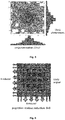
- Each detector block also includes an array of SiPMs as depicted in Fig. 1 right.
- the photosensor matrix is composed of 12 ⁇ 12 SiPMs photosensors with 3 ⁇ 3 mm 2 active area each, and a pitch of 4.2 mm.
- each SiPM has been connected to the aforementioned projection readout circuitry that provides scintillation light profiles in the X and Y axes.
- the readout electronics reduces the 12 signals for each projection to only 8, resulting on a total of 8+8 outputs per photon impact. This reduction is based on keeping the 2 lateral row and columns, but merging the 8 central ones from 2 to 1.
- the proposed readout scheme makes it possible to reduce the total number of signals of a detector of 144 photosensors to only 16.
- the performance of the proposed detector block module including the projection reduction readout system has been compared to a standard 8 ⁇ 8 SiPMs photosensors with a 6 ⁇ 6 mm 2 active area, and a pitch of 6.33 mm.
- the performance of the detector block described above was evaluated by means of the spatial, energy and DOI resolutions. Perpendicular to entrance face and lateral incidence measurements to the crystal were carried out.
- the module under study was irradiated with an array of 11 ⁇ 11 22 Na sources, 1 mm in diameter and 1 mm height each (4.6 mm pitch), placed in front of a Tungsten collimator (24 mm thick, 1.2 mm diameter holes), which was in contact with the crystal.
- the centroids of the measured scintillation light distributions, through the projection readout circuit, are calculated using the center of gravity methods.
- the photon impact DOI is estimated by the ratio of the sum of all 8 signals (photon energy, E) to the maximum signal value ( E / Imax ).
- each detector area is subdivided in 600 ⁇ 600 virtual pixels, and a software collimation was applied.
- An energy window of 15% at the 511 keV peak was also applied in the data analysis.
- the collimation aperture must guarantee the best compromise between the detector spatial resolution and the measurement statistics of the analyzed measurement.
- the measured detector spatial resolution was evaluated using the imaged 11 ⁇ 11 22 Na collimated sources, as shown in Fig. 11 left. We calculated the centroid of each source in channels, as shown in the profile of the top panel in Fig. 11 right, using multi-Gaussian distributions. After the calibration to metric units, it is possible to obtain the measured detector spatial resolution for each source as the FWHM. The spatial resolution for each source was calculated as the average of the X and Y projections, and as a function of the DOI layer. The top right panel in Fig. 11 shows the profile of the central row of sources calibrated into mm, the 11 sources can be well distinguished. Right-bottom, DOI distribution of a source placed at 15 mm from the edge. The energy resolution is determined as FWHM/E centroid . This was done for each selected DOI range.
- lateral incidence measurements were carried out in steps of 1 mm also using the pinhole collimator. ROIs of 4 ⁇ 4 mm 2 were carried out at step distances of 5 mm from the crystal edge, reaching the crystal center. This allows one characterization of the DOI in the whole volume of the scintillator.
- DOI1 Entrance
- DOI2 exit
- DOI3 exit
- the main advantages of the detector block according to the invention is a new readout electronics permits to reduce the 144 photosensor elements information to only 8+8 signals without significant detector performance degradation.
- This approach also allows for resolving radioactive sources in the whole volume of the proposed crystal, but with a significant reduction of readout signals to be processed (from 144 to 16).
- Figure 9 depicts the results of an experiment carried out comparing the third alternative (projection reduction readout electronics) on a 12 ⁇ 12 photosensor with a more used projection readout for both 12 ⁇ 12 and 8 ⁇ 8 SiPM array. That means using 8+8, 12+12 and 8+8 signals respectively.
- One of the columns of sources was placed at 2.5 mm from the crystal edge.
- Both the projection reduction readout and the projection readout for the 12 ⁇ 12 array made it possible to resolve these impacts at 2.5 mm from the edge.
- the 8 ⁇ 8 array with also 8+8 signals did not allow one for this. Therefore, the current invention shows how to reduce the number of channel without performance decrease at the edges.
Landscapes
- Physics & Mathematics (AREA)
- Health & Medical Sciences (AREA)
- Life Sciences & Earth Sciences (AREA)
- General Physics & Mathematics (AREA)
- High Energy & Nuclear Physics (AREA)
- Molecular Biology (AREA)
- Spectroscopy & Molecular Physics (AREA)
- Nuclear Medicine (AREA)
- Measurement Of Radiation (AREA)
Priority Applications (2)
| Application Number | Priority Date | Filing Date | Title |
|---|---|---|---|
| EP17382769.2A EP3483633A1 (de) | 2017-11-14 | 2017-11-14 | Verfahren zur reduzierung der anzahl von auszulesenen signalen in einem detektor |
| US15/989,892 US20190146099A1 (en) | 2017-11-14 | 2018-05-25 | Method to Reduce the Number of Signals to be Read Out in a Detector |
Applications Claiming Priority (1)
| Application Number | Priority Date | Filing Date | Title |
|---|---|---|---|
| EP17382769.2A EP3483633A1 (de) | 2017-11-14 | 2017-11-14 | Verfahren zur reduzierung der anzahl von auszulesenen signalen in einem detektor |
Publications (1)
| Publication Number | Publication Date |
|---|---|
| EP3483633A1 true EP3483633A1 (de) | 2019-05-15 |
Family
ID=60327261
Family Applications (1)
| Application Number | Title | Priority Date | Filing Date |
|---|---|---|---|
| EP17382769.2A Withdrawn EP3483633A1 (de) | 2017-11-14 | 2017-11-14 | Verfahren zur reduzierung der anzahl von auszulesenen signalen in einem detektor |
Country Status (2)
| Country | Link |
|---|---|
| US (1) | US20190146099A1 (de) |
| EP (1) | EP3483633A1 (de) |
Families Citing this family (1)
| Publication number | Priority date | Publication date | Assignee | Title |
|---|---|---|---|---|
| CN121208788A (zh) * | 2024-06-26 | 2025-12-26 | 上海禾赛科技有限公司 | 用于激光雷达的接收器、激光雷达和终端设备 |
Citations (7)
| Publication number | Priority date | Publication date | Assignee | Title |
|---|---|---|---|---|
| EP1104890A2 (de) * | 1994-10-04 | 2001-06-06 | Adac Laboratories | Gammakamerasystem |
| US20030095629A1 (en) * | 2001-11-17 | 2003-05-22 | Augusto Nascetti | Arrangement of sensor elements |
| US6747263B1 (en) | 2001-12-07 | 2004-06-08 | Southeastern University Research Assn. Inc. | Matrix output device readout system |
| US20090242779A1 (en) * | 2006-06-05 | 2009-10-01 | Christian De Godzinsky | X-ray imaging sensor and x-ray imaging method |
| US20130009267A1 (en) * | 2011-07-06 | 2013-01-10 | Siemens Medical Solutions Usa, Inc. | Providing Variable Cell Density and Sizes in a Radiation Detector |
| US20130009066A1 (en) * | 2011-07-06 | 2013-01-10 | Siemens Aktiengesellschaft | Block Detector With Variable Microcell Size For Optimal Light Collection |
| US20130293296A1 (en) | 2012-05-02 | 2013-11-07 | Adaptive I/O Technologies, Inc. | Diode enhanced amplifier circuits and methods thereof |
-
2017
- 2017-11-14 EP EP17382769.2A patent/EP3483633A1/de not_active Withdrawn
-
2018
- 2018-05-25 US US15/989,892 patent/US20190146099A1/en not_active Abandoned
Patent Citations (7)
| Publication number | Priority date | Publication date | Assignee | Title |
|---|---|---|---|---|
| EP1104890A2 (de) * | 1994-10-04 | 2001-06-06 | Adac Laboratories | Gammakamerasystem |
| US20030095629A1 (en) * | 2001-11-17 | 2003-05-22 | Augusto Nascetti | Arrangement of sensor elements |
| US6747263B1 (en) | 2001-12-07 | 2004-06-08 | Southeastern University Research Assn. Inc. | Matrix output device readout system |
| US20090242779A1 (en) * | 2006-06-05 | 2009-10-01 | Christian De Godzinsky | X-ray imaging sensor and x-ray imaging method |
| US20130009267A1 (en) * | 2011-07-06 | 2013-01-10 | Siemens Medical Solutions Usa, Inc. | Providing Variable Cell Density and Sizes in a Radiation Detector |
| US20130009066A1 (en) * | 2011-07-06 | 2013-01-10 | Siemens Aktiengesellschaft | Block Detector With Variable Microcell Size For Optimal Light Collection |
| US20130293296A1 (en) | 2012-05-02 | 2013-11-07 | Adaptive I/O Technologies, Inc. | Diode enhanced amplifier circuits and methods thereof |
Non-Patent Citations (2)
| Title |
|---|
| A. GONZALEZ-MONTORO ET AL., IEEE TRANS. RADIATION PLASMA MEDICAL SCI., vol. 1, 2017, pages 229 |
| A.J. GONZALEZ ET AL., IEEE TRANS. NUCL. SCI., vol. 63, 2016, pages 2471 |
Also Published As
| Publication number | Publication date |
|---|---|
| US20190146099A1 (en) | 2019-05-16 |
Similar Documents
| Publication | Publication Date | Title |
|---|---|---|
| US6288399B1 (en) | Depth of interaction detector block for high resolution positron emission tomography | |
| US12265190B2 (en) | High resolution depth-encoding pet detector with prismatoid light guide array | |
| González-Montoro et al. | Detector block performance based on a monolithic LYSO crystal using a novel signal multiplexing method | |
| US10234572B2 (en) | Multiple spatial resolution scintillation detectors | |
| US6791090B2 (en) | Compton deconvolution camera | |
| US20100044571A1 (en) | Method for determining the three-dimensional position of a scintillation event | |
| CN102262237B (zh) | 光子辐射检测装置和此种装置的定制和运行方法 | |
| US8481947B2 (en) | Method and system for nuclear imaging using multi-zone detector architecture | |
| JP7317586B2 (ja) | 医用画像処理装置、方法及びプログラム | |
| Vaquero et al. | Performance characteristics of a compact position-sensitive LSO detector module | |
| US8507842B2 (en) | Method for identifying 3-D location of gamma interaction and flat panel gamma imaging head apparatus using the same | |
| US11543545B2 (en) | Method and apparatus to use a broad-spectrum energy source to correct a nonlinear energy response of a gamma-ray detector | |
| EP4088142A2 (de) | Ionenstrahlemissionsvorrichtung und detektionssystem dafür | |
| Pani et al. | Preliminary evaluation of a monolithic detector module for integrated PET/MRI scanner with high spatial resolution | |
| CN112470039B (zh) | 用于通过伽马辐射探测进行成像的系统和方法 | |
| Pani et al. | A Novel Method for $\gamma-\text {photons} $ Depth-of-Interaction Detection in Monolithic Scintillation Crystals | |
| US8809790B2 (en) | Method and system for nuclear imaging using multi-zone detector architecture | |
| EP3483633A1 (de) | Verfahren zur reduzierung der anzahl von auszulesenen signalen in einem detektor | |
| Aguiar et al. | A feasibility study on the use of arrays of discrete SiPMs for MR compatible LYSO readout using Monte Carlo simulation | |
| US12078766B2 (en) | Device for the detection of gamma rays with interaction depth and time-of-flight encoding | |
| Sharma et al. | Hit-time and hit-position reconstruction in strips of plastic scintillators using multithreshold readouts | |
| Zhao et al. | A continuous depth encoding PET detector using side readout of dual-layer GAGG crystals with SiPM array | |
| Pratiwi et al. | Performance of a 0.4 mm pixelated Ce: GAGG block detector with digital silicon photomultiplier | |
| Saoudi et al. | A novel APD-based detector module for multi-modality PET/SPECT/CT scanners | |
| Heemskerk et al. | An enhanced high-resolution EMCCD-based gamma camera using SiPM side detection |
Legal Events
| Date | Code | Title | Description |
|---|---|---|---|
| PUAI | Public reference made under article 153(3) epc to a published international application that has entered the european phase |
Free format text: ORIGINAL CODE: 0009012 |
|
| STAA | Information on the status of an ep patent application or granted ep patent |
Free format text: STATUS: THE APPLICATION HAS BEEN PUBLISHED |
|
| AK | Designated contracting states |
Kind code of ref document: A1 Designated state(s): AL AT BE BG CH CY CZ DE DK EE ES FI FR GB GR HR HU IE IS IT LI LT LU LV MC MK MT NL NO PL PT RO RS SE SI SK SM TR |
|
| AX | Request for extension of the european patent |
Extension state: BA ME |
|
| STAA | Information on the status of an ep patent application or granted ep patent |
Free format text: STATUS: REQUEST FOR EXAMINATION WAS MADE |
|
| 17P | Request for examination filed |
Effective date: 20191112 |
|
| RBV | Designated contracting states (corrected) |
Designated state(s): AL AT BE BG CH CY CZ DE DK EE ES FI FR GB GR HR HU IE IS IT LI LT LU LV MC MK MT NL NO PL PT RO RS SE SI SK SM TR |
|
| STAA | Information on the status of an ep patent application or granted ep patent |
Free format text: STATUS: THE APPLICATION IS DEEMED TO BE WITHDRAWN |
|
| 18D | Application deemed to be withdrawn |
Effective date: 20210601 |