EP3483909A1 - Équipement de commutation de transfert automatique et son mécanisme de fonctionnement manuel - Google Patents
Équipement de commutation de transfert automatique et son mécanisme de fonctionnement manuel Download PDFInfo
- Publication number
- EP3483909A1 EP3483909A1 EP18206039.2A EP18206039A EP3483909A1 EP 3483909 A1 EP3483909 A1 EP 3483909A1 EP 18206039 A EP18206039 A EP 18206039A EP 3483909 A1 EP3483909 A1 EP 3483909A1
- Authority
- EP
- European Patent Office
- Prior art keywords
- gear
- handle
- energy
- storing
- driving gear
- Prior art date
- Legal status (The legal status is an assumption and is not a legal conclusion. Google has not performed a legal analysis and makes no representation as to the accuracy of the status listed.)
- Withdrawn
Links
Images




Classifications
-
- H—ELECTRICITY
- H01—ELECTRIC ELEMENTS
- H01H—ELECTRIC SWITCHES; RELAYS; SELECTORS; EMERGENCY PROTECTIVE DEVICES
- H01H3/00—Mechanisms for operating contacts
- H01H3/32—Driving mechanisms, i.e. for transmitting driving force to the contacts
- H01H3/46—Driving mechanisms, i.e. for transmitting driving force to the contacts using rod or lever linkage, e.g. toggle
-
- H—ELECTRICITY
- H01—ELECTRIC ELEMENTS
- H01H—ELECTRIC SWITCHES; RELAYS; SELECTORS; EMERGENCY PROTECTIVE DEVICES
- H01H3/00—Mechanisms for operating contacts
- H01H3/32—Driving mechanisms, i.e. for transmitting driving force to the contacts
- H01H3/40—Driving mechanisms, i.e. for transmitting driving force to the contacts using friction, toothed, or screw-and-nut gearing
-
- H—ELECTRICITY
- H01—ELECTRIC ELEMENTS
- H01H—ELECTRIC SWITCHES; RELAYS; SELECTORS; EMERGENCY PROTECTIVE DEVICES
- H01H3/00—Mechanisms for operating contacts
- H01H3/32—Driving mechanisms, i.e. for transmitting driving force to the contacts
- H01H3/40—Driving mechanisms, i.e. for transmitting driving force to the contacts using friction, toothed, or screw-and-nut gearing
- H01H2003/405—Driving mechanisms, i.e. for transmitting driving force to the contacts using friction, toothed, or screw-and-nut gearing using a walking nut
-
- H—ELECTRICITY
- H01—ELECTRIC ELEMENTS
- H01H—ELECTRIC SWITCHES; RELAYS; SELECTORS; EMERGENCY PROTECTIVE DEVICES
- H01H2300/00—Orthogonal indexing scheme relating to electric switches, relays, selectors or emergency protective devices covered by H01H
- H01H2300/018—Application transfer; between utility and emergency power supply
Definitions
- the present application relates to a manual operating mechanism for automatic transfer switching equipment and an automatic transfer switching equipment comprising such a manual operating mechanism.
- ATSE Automatic transfer switching equipment
- the operating mechanism of the ATSE is a key component for the reliability. It is important to provide an easy and reliable operating mechanism.
- operating mechanism There are two types of operating mechanism, one is electrical operating mechanism and the other is manual operating mechanism. Generally, the electrical operating mechanism is used to control the transfer of the ATSE, but in the case that the electrical operating mechanism is failed or needs repair, the manual operating mechanism is used to control the transfer of the ATSE.
- manual operating mechanism There are two types of manual operating mechanism, one is manpower manual operating mechanism and non-manpower manual operating mechanism. Current manual operating mechanism is manpower manual operating mechanism, which requires users to disconnect the power supply or the load when operating, otherwise a serious safety problem may be occurred since the electric arc generated between the mobile contact and the fixed contact is uncontrollable, which is undesirable for the users.
- the present application proposes a manual operating mechanism for automatic transfer switching equipment, the automatic transfer switching equipment being capable of transfer between an OFF position, a first power supply ON position and a second power supply ON position, characterized in that the manual operating mechanism comprises: a handle gear pivotally mounted on a frame; a handle connecting with the handle gear such that the handle gear is capable of rotating with the handle, the handle being capable of moving between a first position corresponding to the OFF position, a second position corresponding to the first power supply ON position and a third position corresponding to the second power supply ON position; a first energy-storing gear pivotally mounted on the frame, wherein the first energy-storing gear is capable of engage with the handle gear to rotate during the rotation of the handle gear; a first driving gear pivotally mounted on the frame and being coaxial with the first energy-storing gear; a first elastic element provided on the first energy-storing gear at one end and provided on the first driving gear at the other end; a central wheel pivotally mounted on the frame and being
- the handle gear when the handle is rotated towards the first position along the second direction, the handle gear is also rotated along the second direction to engage with the first energy-storing gear, such that the first energy-storing gear rotates along the first direction and at this time the first driving gear is unable to rotate in the first direction due to the second stopper provided on the frame, wherein with the rotating of the first energy-storing gear, the first elastic element will deform to store energy and when the first elastic element passes a "dead point", the first driving gear rotates along the second direction upon the elastic force of the first elastic element to engage with the central wheel such that the central wheel rotates along the first direction to force the main shaft of the automatic transfer switching equipment to rotate to transfer the automatic transfer switching equipment to the OFF position and at last the first driving gear is unable to rotate along the second direction due to the first stopper.
- the manual operating mechanism further comprises: a second energy-storing gear pivotally mounted on the frame, wherein the second energy-storing gear is capable of engage with the handle gear to rotate during the rotation of the handle gear; a second driving gear, pivotally mounted on the frame and being coaxial with the second energy-storing gear; a second elastic element provided on the second energy-storing gear at one end and provided on the second driving gear at the other end, wherein in the case that the automatic transfer switching equipment is at OFF position and the handle is at the first position, when the handle is rotated towards the third position along the second direction, the handle gear is also rotated along the second direction to engage with the second energy-storing gear, such that the second energy-storing gear rotates along the first direction and at this time the second driving gear is unable to rotate in the first direction due to the third stopper provided on the frame, wherein with the rotating of the second energy-storing gear, the second elastic element will deform to store energy and when the second elastic element passes a "dead point", the second driving gear rotates along the second direction upon
- the handle gear when the handle is rotated towards the first position along the first direction, the handle gear is also rotated along the first direction to engage with the second energy-storing gear, such that the second energy-storing gear rotates along the second direction and at this time the second driving gear is unable to rotate in the second direction due to the fourth stopper provided on the frame, wherein with the rotating of the second energy-storing gear, the second elastic element will deform to store energy and when the second elastic element passes a "dead point", the second driving gear rotates along the first direction upon the elastic force of the second elastic element to engage with the central wheel such that the central wheel rotates along the second direction to force the main shaft of the automatic transfer switching equipment to rotate to transfer the automatic transfer switching equipment to the OFF position and at last the second driving gear is unable to rotate along the first direction due to the third stopper.
- the teeth of the handle gear are only arranged on a portion of the circumference of the handle gear such that the handle gear is not engaged with the second energy-storing gear when the handle gear is engaged with the first energy-storing gear and the handle gear is not engaged with the first energy-storing gear when the handle gear is engaged with the second energy-storing gear.
- the teeth of the first driving gear are only arranged on a portion of the circumference of the first driving gear such that the central wheel is not engaged with the teeth of the first driving gear when the second driving gear is engaged with the central wheel.
- the teeth of the second driving gear are only arranged on a portion of the circumference of the second driving gear such that the central wheel is not engaged with the teeth of the second driving gear when the first driving gear is engaged with the central wheel.
- the handle gear, the first driving gear and the second driving gear are external gear or internal gear.
- the present application also proposes an automatic transfer switching equipment comprising the manual operating mechanism described above.
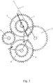
- a manual operating mechanism of the present application is shown.
- the handle of the manual operating mechanism is at the first position corresponding to the OFF position of the ATSE and at the same time the ATSE is at OFF position.
- the manual operating mechanism comprises a handle 1 which is capable of moving between a first position corresponding to the OFF position, a second position corresponding to the first power supply ON position and a third position corresponding to the second power supply ON position.
- a handle gear 2 is pivotally mounted on a frame and fixedly connected with the handle such that the handle gear 2 is capable of rotating with the handle 1.
- a first energy-storing gear 3 and a second energy-storing gear 4 are pivotally mounted on the frame and are capable of engaging with the handle gear 2 during the rotation of the handle gear such that the first energy-storing gear and a second energy-storing gear can rotate.
- a first driving gear 5 is pivotally mounted on the frame and is coaxial with the first energy-storing gear 3.
- a second driving gear 6 is pivotally mounted on the frame and is coaxial with the second energy-storing gear 4.
- a first elastic element 7 is provided between the first energy-storing gear 3 and the first driving gear 5.
- a second elastic element 8 is provided between the second energy-storing gear 4 and the second driving gear 6.
- the central wheel 9 is connected with a main shaft of the ATSE such that the rotation of the central wheel makes the main shaft rotate and thereby the mobile contact of the ATSE switches between the OFF position, the first power supply ON position and the second power supply ON position.
- the handle gear 2 When the handle 1 is rotated in counter-clockwise direction, the handle gear 2 is also rotated in counter-clockwise direction.
- the handle gear will engage with the first energy-storing gear 3 during the rotation in counter-clockwise direction such that the first energy-storing gear 3 rotates in clockwise direction and the first elastic element 7 which is mounted on the first energy-storing gear at one end deforms and stores energy.
- the first driving gear 5 remains stationary by a first stopper mounted on the frame.
- the first stopper prevents the first driving gear from rotating in clockwise direction upon the action of the first elastic element 7.
- the first driving gear 5 After the first elastic element 7 passes a "dead point", as shown in Fig.3 , the first driving gear 5 will rotate in counter-clockwise direction upon the elastic force of the first elastic element 7.
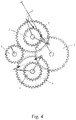
- the "dead point” is defined as a position in which the elastic force applied to the first energy-storing gear 3 by the first elastic element is coincided with the central axis of the first energy-storing gear. Then, the first driving gear 5 rotates in counter-clockwise direction to engage with the central wheel 9, causing the central wheel rotates in clockwise direction and the main shaft of the ATSE rotates correspondingly to switch to the first power supply ON position, as shown in Fig. 4 .
- the handle is at the second position and the ATSE is at the first power supply ON position.
- the handle gear 2 is also rotated in clockwise direction.
- the handle gear will engage with the first energy-storing gear 3 during the rotation in clockwise direction such that the first energy-storing gear rotates in counter-clockwise direction, and the first elastic element 7 which is mounted on the first energy-storing gear at one end deforms and stores energy.
- the first driving gear 5 remains stationary by a second stopper mounted on the frame. The second stopper prevents the first driving gear from rotating in counter-clockwise direction upon the action of the first elastic element 7.
- the first driving gear 5 After the first elastic element 7 passes a "dead point", the first driving gear 5 will rotate in clockwise direction upon the elastic force of the first elastic element 7. Then, the first driving gear 5 rotates in clockwise direction to engage with the central wheel 9, causing the central wheel 9 rotates in counter-clockwise direction and the main shaft of the ATSE rotates correspondingly to switch to the OFF position.
- the handle gear 2 When the handle 1 is rotated in clockwise direction, the handle gear 2 is also rotated in clockwise direction.
- the handle gear will engage with the second energy-storing gear 4 during the rotation in clockwise direction such that the second energy-storing gear rotates in counter-clockwise direction and the second elastic element 8 which is mounted on the second energy-storing gear at one end deforms and stores energy.
- the second driving gear 6 remains stationary by a third stopper mounted on the frame.
- the third stopper prevents the second driving gear from rotating in counter-clockwise direction upon the action of the second elastic element 8.
- the second elastic element 8 passes a "dead point", as shown in Fig.7 , the second driving gear 6 will rotate in clockwise direction upon the elastic force of the second elastic element 8.
- the "dead point” is defined as a position in which the elastic force applied to the second energy-storing gear 4 by the second elastic element is coincided with the central axis of the second energy-storing gear. Then, the second driving gear 6 rotates in clockwise direction to engage with the central wheel 9, causing the central wheel 9 rotates in counter-clockwise direction and the main shaft of the ATSE rotates correspondingly to switch to the second power supply ON position, as shown in Fig. 8 .
- the teeth of the handle gear 2, the first driving gear 5 and the second driving gear 6 are only arranged on a portion of the circumference.
- the handle gear can only engage with one of the first energy-storing gear and the second energy-storing gear and cannot engage with both of the first energy-storing gear and the second energy-storing gear at the same time.
- only one of the first driving gear and the second driving gear can engage with the central wheel and the central wheel cannot engage with both of the first driving gear and the second driving gear at the same time.
- the handle gear 2 can only engage with the first energy-storing gear and cannot engage with the second energy-storing gear.
- the handle gear 2 can only engage with the second energy-storing gear and cannot engage with the first energy-storing gear. Only the second driving gear can engage with the central wheel and the first driving gear cannot engage with the central wheel.
- the handle gear, the first driving gear and the second driving gear are internal gear, but the handle gear, the first driving gear and the second driving gear can also be external gear.
- a manual operating mechanism comprising a handle gear, energy-storing gears, driving gears and a central wheel is described above. Due to the manual operating mechanism of the present application, during the switching of the ATSE, the rotating speed of the mobile contact is irrelevant to the switching speed of the ATSE and the electric arc generated between the mobile contact and the fixed contact is controllable within an allowable range, and thereby it is not necessary to disconnect the power supply or the load.
- a process of switching the ATSE from the OFF position to the first power supply ON position by switching the handle of the manual operating mechanism from the first position to the second position, a process of switching the ATSE from the first power supply On position to the OFF position by switching the handle of the manual operating mechanism from the second position to the first position and a process of switching the ATSE from the OFF position to the second power supply ON position by switching the handle of the manual operating mechanism from the first position to the third position are described above, but based on the teaching of the present application, a skilled person can conceive of switching the handle of the manual operating mechanism from the third position to the first position.
Landscapes
- Transmission Devices (AREA)
Applications Claiming Priority (2)
| Application Number | Priority Date | Filing Date | Title |
|---|---|---|---|
| CN201721511519.1U CN207381284U (zh) | 2017-11-13 | 2017-11-13 | 双电源转换开关及其手动操作机构 |
| CN201711120191.5A CN109786143B (zh) | 2017-11-13 | 2017-11-13 | 双电源转换开关及其手动操作机构 |
Publications (1)
| Publication Number | Publication Date |
|---|---|
| EP3483909A1 true EP3483909A1 (fr) | 2019-05-15 |
Family
ID=64308664
Family Applications (1)
| Application Number | Title | Priority Date | Filing Date |
|---|---|---|---|
| EP18206039.2A Withdrawn EP3483909A1 (fr) | 2017-11-13 | 2018-11-13 | Équipement de commutation de transfert automatique et son mécanisme de fonctionnement manuel |
Country Status (1)
| Country | Link |
|---|---|
| EP (1) | EP3483909A1 (fr) |
Citations (6)
| Publication number | Priority date | Publication date | Assignee | Title |
|---|---|---|---|---|
| US20080245645A1 (en) * | 2007-04-09 | 2008-10-09 | Asco Power Technologies, L.P. | Three-position apparatus capable of positioning an electrical transfer switch |
| WO2011072541A1 (fr) * | 2009-12-16 | 2011-06-23 | 中国西电电气股份有限公司 | Mécanisme électrique de fonctionnement pour appareillage |
| CN101826403B (zh) * | 2009-03-05 | 2012-07-25 | 上海电科电器科技有限公司 | 单操作轴的双储能操作机构 |
| WO2014131170A1 (fr) * | 2013-02-28 | 2014-09-04 | General Electric Company | Système de commutateur de transfert électrique |
| GB2520528A (en) * | 2013-11-22 | 2015-05-27 | Eaton Ind Netherlands Bv | Switching device |
| CN207637646U (zh) * | 2017-11-13 | 2018-07-20 | 施耐德电器工业公司 | 双电源转换开关及用于其的离合式手动操作机构 |
-
2018
- 2018-11-13 EP EP18206039.2A patent/EP3483909A1/fr not_active Withdrawn
Patent Citations (6)
| Publication number | Priority date | Publication date | Assignee | Title |
|---|---|---|---|---|
| US20080245645A1 (en) * | 2007-04-09 | 2008-10-09 | Asco Power Technologies, L.P. | Three-position apparatus capable of positioning an electrical transfer switch |
| CN101826403B (zh) * | 2009-03-05 | 2012-07-25 | 上海电科电器科技有限公司 | 单操作轴的双储能操作机构 |
| WO2011072541A1 (fr) * | 2009-12-16 | 2011-06-23 | 中国西电电气股份有限公司 | Mécanisme électrique de fonctionnement pour appareillage |
| WO2014131170A1 (fr) * | 2013-02-28 | 2014-09-04 | General Electric Company | Système de commutateur de transfert électrique |
| GB2520528A (en) * | 2013-11-22 | 2015-05-27 | Eaton Ind Netherlands Bv | Switching device |
| CN207637646U (zh) * | 2017-11-13 | 2018-07-20 | 施耐德电器工业公司 | 双电源转换开关及用于其的离合式手动操作机构 |
Similar Documents
| Publication | Publication Date | Title |
|---|---|---|
| KR101604278B1 (ko) | 스위치기어의 3위치 조작기 | |
| AU2019236615B2 (en) | An operating mechanism for rotary switch | |
| US10784060B2 (en) | Dual-power overlapping contact closing mechanism | |
| WO2014032584A1 (fr) | Appareil de verrouillage de commutateur de transfert automatique | |
| KR101690132B1 (ko) | 가스절연 개폐기의 인터록 장치 | |
| CN105405694A (zh) | 断路器与隔离开关的联锁装置 | |
| EP3483909A1 (fr) | Équipement de commutation de transfert automatique et son mécanisme de fonctionnement manuel | |
| CN107887221A (zh) | 新型abb负荷开关组合电器机构 | |
| CN104601048A (zh) | 能快速分断的电机起动器的操作机构 | |
| EP4318518B1 (fr) | Mécanisme d'actionnement de dispositif de commutation, et dispositif de commutation | |
| CN105047469B (zh) | 转轴转动限位机构及使用该机构的轴系和三工位电气开关 | |
| CN101814384B (zh) | 一种双电源开关及其中性线重叠转换方法 | |
| JP2016504716A (ja) | 特に高電圧または中電圧の回路ブレーカまたはスイッチのためのバネタイプ制御装置 | |
| CN207381284U (zh) | 双电源转换开关及其手动操作机构 | |
| CN205303238U (zh) | 一种断路器与隔离开关的联锁装置 | |
| CN204011151U (zh) | 一种双电源切换开关 | |
| CN107425424A (zh) | 开关柜及其操作机构、联动机构 | |
| CN106356216B (zh) | 用于电气设备的机械联锁机构 | |
| CN207282387U (zh) | 一种开关柜及其操作机构、联动机构 | |
| US10242813B2 (en) | Indication device of electric switch | |
| CN101459009A (zh) | 快速断开闭合负荷隔离开关的开关装置 | |
| CN109786143B (zh) | 双电源转换开关及其手动操作机构 | |
| CN109994337A (zh) | 一种断路器的机械连锁结构和机械连锁装置 | |
| CN106653456A (zh) | 一种电梯用超薄型电源锁 | |
| CN204376780U (zh) | 能快速分断的电机起动器的操作机构 |
Legal Events
| Date | Code | Title | Description |
|---|---|---|---|
| PUAI | Public reference made under article 153(3) epc to a published international application that has entered the european phase |
Free format text: ORIGINAL CODE: 0009012 |
|
| STAA | Information on the status of an ep patent application or granted ep patent |
Free format text: STATUS: THE APPLICATION HAS BEEN PUBLISHED |
|
| AK | Designated contracting states |
Kind code of ref document: A1 Designated state(s): AL AT BE BG CH CY CZ DE DK EE ES FI FR GB GR HR HU IE IS IT LI LT LU LV MC MK MT NL NO PL PT RO RS SE SI SK SM TR |
|
| AX | Request for extension of the european patent |
Extension state: BA ME |
|
| STAA | Information on the status of an ep patent application or granted ep patent |
Free format text: STATUS: REQUEST FOR EXAMINATION WAS MADE |
|
| 17P | Request for examination filed |
Effective date: 20191113 |
|
| RBV | Designated contracting states (corrected) |
Designated state(s): AL AT BE BG CH CY CZ DE DK EE ES FI FR GB GR HR HU IE IS IT LI LT LU LV MC MK MT NL NO PL PT RO RS SE SI SK SM TR |
|
| STAA | Information on the status of an ep patent application or granted ep patent |
Free format text: STATUS: EXAMINATION IS IN PROGRESS |
|
| 17Q | First examination report despatched |
Effective date: 20200923 |
|
| GRAP | Despatch of communication of intention to grant a patent |
Free format text: ORIGINAL CODE: EPIDOSNIGR1 |
|
| STAA | Information on the status of an ep patent application or granted ep patent |
Free format text: STATUS: GRANT OF PATENT IS INTENDED |
|
| INTG | Intention to grant announced |
Effective date: 20230120 |
|
| STAA | Information on the status of an ep patent application or granted ep patent |
Free format text: STATUS: THE APPLICATION IS DEEMED TO BE WITHDRAWN |
|
| 18D | Application deemed to be withdrawn |
Effective date: 20230531 |