EP3484004A1 - Système de commande et procédé de localisation de défaut, d'isolation et de restauration d'alimentation - Google Patents
Système de commande et procédé de localisation de défaut, d'isolation et de restauration d'alimentation Download PDFInfo
- Publication number
- EP3484004A1 EP3484004A1 EP17200688.4A EP17200688A EP3484004A1 EP 3484004 A1 EP3484004 A1 EP 3484004A1 EP 17200688 A EP17200688 A EP 17200688A EP 3484004 A1 EP3484004 A1 EP 3484004A1
- Authority
- EP
- European Patent Office
- Prior art keywords
- electrical power
- reconnection
- segments
- segment
- region
- Prior art date
- Legal status (The legal status is an assumption and is not a legal conclusion. Google has not performed a legal analysis and makes no representation as to the accuracy of the status listed.)
- Pending
Links
Images




Classifications
-
- H—ELECTRICITY
- H02—GENERATION; CONVERSION OR DISTRIBUTION OF ELECTRIC POWER
- H02H—EMERGENCY PROTECTIVE CIRCUIT ARRANGEMENTS
- H02H3/00—Emergency protective circuit arrangements for automatic disconnection directly responsive to an undesired change from normal electric working condition with or without subsequent reconnection ; integrated protection
- H02H3/02—Details
- H02H3/033—Details with several disconnections in a preferential order, e.g. following priority of the users, load repartition
-
- H—ELECTRICITY
- H02—GENERATION; CONVERSION OR DISTRIBUTION OF ELECTRIC POWER
- H02H—EMERGENCY PROTECTIVE CIRCUIT ARRANGEMENTS
- H02H3/00—Emergency protective circuit arrangements for automatic disconnection directly responsive to an undesired change from normal electric working condition with or without subsequent reconnection ; integrated protection
- H02H3/02—Details
- H02H3/06—Details with automatic reconnection
- H02H3/063—Details concerning the co-operation of many similar arrangements, e.g. in a network
-
- H—ELECTRICITY
- H02—GENERATION; CONVERSION OR DISTRIBUTION OF ELECTRIC POWER
- H02H—EMERGENCY PROTECTIVE CIRCUIT ARRANGEMENTS
- H02H7/00—Emergency protective circuit arrangements specially adapted for specific types of electric machines or apparatus or for sectionalised protection of cable or line systems, and effecting automatic switching in the event of an undesired change from normal working conditions
- H02H7/26—Sectionalised protection of cable or line systems, e.g. for disconnecting a section on which a short-circuit, earth fault, or arc discharge has occured
- H02H7/28—Sectionalised protection of cable or line systems, e.g. for disconnecting a section on which a short-circuit, earth fault, or arc discharge has occured for meshed systems
-
- H—ELECTRICITY
- H02—GENERATION; CONVERSION OR DISTRIBUTION OF ELECTRIC POWER
- H02J—ELECTRIC POWER NETWORKS; CIRCUIT ARRANGEMENTS OR SYSTEMS FOR SUPPLYING OR DISTRIBUTING ELECTRIC POWER; SYSTEMS FOR STORING ELECTRIC ENERGY
- H02J3/00—Circuit arrangements for AC mains or AC distribution networks
- H02J3/007—Arrangements for selectively connecting one or more loads to one or more power sources or power lines
- H02J3/0073—Arrangements for selectively connecting one or more loads to one or more power sources or power lines by providing alternative feeding paths when the main path fails
-
- H—ELECTRICITY
- H02—GENERATION; CONVERSION OR DISTRIBUTION OF ELECTRIC POWER
- H02J—ELECTRIC POWER NETWORKS; CIRCUIT ARRANGEMENTS OR SYSTEMS FOR SUPPLYING OR DISTRIBUTING ELECTRIC POWER; SYSTEMS FOR STORING ELECTRIC ENERGY
- H02J13/00—Circuit arrangements for providing remote monitoring or remote control of equipment in a power distribution network
- H02J13/12—Monitoring network conditions, e.g. electrical magnitudes or operational status
-
- H—ELECTRICITY
- H02—GENERATION; CONVERSION OR DISTRIBUTION OF ELECTRIC POWER
- H02J—ELECTRIC POWER NETWORKS; CIRCUIT ARRANGEMENTS OR SYSTEMS FOR SUPPLYING OR DISTRIBUTING ELECTRIC POWER; SYSTEMS FOR STORING ELECTRIC ENERGY
- H02J13/00—Circuit arrangements for providing remote monitoring or remote control of equipment in a power distribution network
- H02J13/18—Circuit arrangements for providing remote monitoring or remote control of equipment in a power distribution network characterised by the remotely-controlled equipment, e.g. converters or transformers
- H02J13/333—Circuit arrangements for providing remote monitoring or remote control of equipment in a power distribution network characterised by the remotely-controlled equipment, e.g. converters or transformers the equipment forming part of substations
-
- H—ELECTRICITY
- H02—GENERATION; CONVERSION OR DISTRIBUTION OF ELECTRIC POWER
- H02J—ELECTRIC POWER NETWORKS; CIRCUIT ARRANGEMENTS OR SYSTEMS FOR SUPPLYING OR DISTRIBUTING ELECTRIC POWER; SYSTEMS FOR STORING ELECTRIC ENERGY
- H02J13/00—Circuit arrangements for providing remote monitoring or remote control of equipment in a power distribution network
- H02J13/18—Circuit arrangements for providing remote monitoring or remote control of equipment in a power distribution network characterised by the remotely-controlled equipment, e.g. converters or transformers
- H02J13/34—Circuit arrangements for providing remote monitoring or remote control of equipment in a power distribution network characterised by the remotely-controlled equipment, e.g. converters or transformers the equipment being switches, relays or circuit breakers
- H02J13/36—Circuit arrangements for providing remote monitoring or remote control of equipment in a power distribution network characterised by the remotely-controlled equipment, e.g. converters or transformers the equipment being switches, relays or circuit breakers specially adapted for protection systems
-
- H—ELECTRICITY
- H02—GENERATION; CONVERSION OR DISTRIBUTION OF ELECTRIC POWER
- H02J—ELECTRIC POWER NETWORKS; CIRCUIT ARRANGEMENTS OR SYSTEMS FOR SUPPLYING OR DISTRIBUTING ELECTRIC POWER; SYSTEMS FOR STORING ELECTRIC ENERGY
- H02J3/00—Circuit arrangements for AC mains or AC distribution networks
- H02J3/001—Arrangements for handling faults or abnormalities, e.g. emergencies or contingencies
- H02J3/0012—Arrangements for handling faults or abnormalities, e.g. emergencies or contingencies characterised by the contingency detection means in AC networks, e.g. using phasor measurement units [PMU], synchrophasors or contingency analysis
-
- Y—GENERAL TAGGING OF NEW TECHNOLOGICAL DEVELOPMENTS; GENERAL TAGGING OF CROSS-SECTIONAL TECHNOLOGIES SPANNING OVER SEVERAL SECTIONS OF THE IPC; TECHNICAL SUBJECTS COVERED BY FORMER USPC CROSS-REFERENCE ART COLLECTIONS [XRACs] AND DIGESTS
- Y02—TECHNOLOGIES OR APPLICATIONS FOR MITIGATION OR ADAPTATION AGAINST CLIMATE CHANGE
- Y02B—CLIMATE CHANGE MITIGATION TECHNOLOGIES RELATED TO BUILDINGS, e.g. HOUSING, HOUSE APPLIANCES OR RELATED END-USER APPLICATIONS
- Y02B70/00—Technologies for an efficient end-user side electric power management and consumption
- Y02B70/30—Systems integrating technologies related to power network operation and communication or information technologies for improving the carbon footprint of the management of residential or tertiary loads, i.e. smart grids as climate change mitigation technology in the buildings sector, including also the last stages of power distribution and the control, monitoring or operating management systems at local level
-
- Y—GENERAL TAGGING OF NEW TECHNOLOGICAL DEVELOPMENTS; GENERAL TAGGING OF CROSS-SECTIONAL TECHNOLOGIES SPANNING OVER SEVERAL SECTIONS OF THE IPC; TECHNICAL SUBJECTS COVERED BY FORMER USPC CROSS-REFERENCE ART COLLECTIONS [XRACs] AND DIGESTS
- Y02—TECHNOLOGIES OR APPLICATIONS FOR MITIGATION OR ADAPTATION AGAINST CLIMATE CHANGE
- Y02B—CLIMATE CHANGE MITIGATION TECHNOLOGIES RELATED TO BUILDINGS, e.g. HOUSING, HOUSE APPLIANCES OR RELATED END-USER APPLICATIONS
- Y02B70/00—Technologies for an efficient end-user side electric power management and consumption
- Y02B70/30—Systems integrating technologies related to power network operation and communication or information technologies for improving the carbon footprint of the management of residential or tertiary loads, i.e. smart grids as climate change mitigation technology in the buildings sector, including also the last stages of power distribution and the control, monitoring or operating management systems at local level
- Y02B70/3225—Demand response systems, e.g. load shedding, peak shaving
-
- Y—GENERAL TAGGING OF NEW TECHNOLOGICAL DEVELOPMENTS; GENERAL TAGGING OF CROSS-SECTIONAL TECHNOLOGIES SPANNING OVER SEVERAL SECTIONS OF THE IPC; TECHNICAL SUBJECTS COVERED BY FORMER USPC CROSS-REFERENCE ART COLLECTIONS [XRACs] AND DIGESTS
- Y02—TECHNOLOGIES OR APPLICATIONS FOR MITIGATION OR ADAPTATION AGAINST CLIMATE CHANGE
- Y02E—REDUCTION OF GREENHOUSE GAS [GHG] EMISSIONS, RELATED TO ENERGY GENERATION, TRANSMISSION OR DISTRIBUTION
- Y02E60/00—Enabling technologies; Technologies with a potential or indirect contribution to GHG emissions mitigation
-
- Y—GENERAL TAGGING OF NEW TECHNOLOGICAL DEVELOPMENTS; GENERAL TAGGING OF CROSS-SECTIONAL TECHNOLOGIES SPANNING OVER SEVERAL SECTIONS OF THE IPC; TECHNICAL SUBJECTS COVERED BY FORMER USPC CROSS-REFERENCE ART COLLECTIONS [XRACs] AND DIGESTS
- Y04—INFORMATION OR COMMUNICATION TECHNOLOGIES HAVING AN IMPACT ON OTHER TECHNOLOGY AREAS
- Y04S—SYSTEMS INTEGRATING TECHNOLOGIES RELATED TO POWER NETWORK OPERATION, COMMUNICATION OR INFORMATION TECHNOLOGIES FOR IMPROVING THE ELECTRICAL POWER GENERATION, TRANSMISSION, DISTRIBUTION, MANAGEMENT OR USAGE, i.e. SMART GRIDS
- Y04S10/00—Systems supporting electrical power generation, transmission or distribution
- Y04S10/20—Systems supporting electrical power generation, transmission or distribution using protection elements, arrangements or systems
-
- Y—GENERAL TAGGING OF NEW TECHNOLOGICAL DEVELOPMENTS; GENERAL TAGGING OF CROSS-SECTIONAL TECHNOLOGIES SPANNING OVER SEVERAL SECTIONS OF THE IPC; TECHNICAL SUBJECTS COVERED BY FORMER USPC CROSS-REFERENCE ART COLLECTIONS [XRACs] AND DIGESTS
- Y04—INFORMATION OR COMMUNICATION TECHNOLOGIES HAVING AN IMPACT ON OTHER TECHNOLOGY AREAS
- Y04S—SYSTEMS INTEGRATING TECHNOLOGIES RELATED TO POWER NETWORK OPERATION, COMMUNICATION OR INFORMATION TECHNOLOGIES FOR IMPROVING THE ELECTRICAL POWER GENERATION, TRANSMISSION, DISTRIBUTION, MANAGEMENT OR USAGE, i.e. SMART GRIDS
- Y04S10/00—Systems supporting electrical power generation, transmission or distribution
- Y04S10/30—State monitoring, e.g. fault, temperature monitoring, insulator monitoring, corona discharge
-
- Y—GENERAL TAGGING OF NEW TECHNOLOGICAL DEVELOPMENTS; GENERAL TAGGING OF CROSS-SECTIONAL TECHNOLOGIES SPANNING OVER SEVERAL SECTIONS OF THE IPC; TECHNICAL SUBJECTS COVERED BY FORMER USPC CROSS-REFERENCE ART COLLECTIONS [XRACs] AND DIGESTS
- Y04—INFORMATION OR COMMUNICATION TECHNOLOGIES HAVING AN IMPACT ON OTHER TECHNOLOGY AREAS
- Y04S—SYSTEMS INTEGRATING TECHNOLOGIES RELATED TO POWER NETWORK OPERATION, COMMUNICATION OR INFORMATION TECHNOLOGIES FOR IMPROVING THE ELECTRICAL POWER GENERATION, TRANSMISSION, DISTRIBUTION, MANAGEMENT OR USAGE, i.e. SMART GRIDS
- Y04S10/00—Systems supporting electrical power generation, transmission or distribution
- Y04S10/50—Systems or methods supporting the power network operation or management, involving a certain degree of interaction with the load-side end user applications
- Y04S10/52—Outage or fault management, e.g. fault detection or location
-
- Y—GENERAL TAGGING OF NEW TECHNOLOGICAL DEVELOPMENTS; GENERAL TAGGING OF CROSS-SECTIONAL TECHNOLOGIES SPANNING OVER SEVERAL SECTIONS OF THE IPC; TECHNICAL SUBJECTS COVERED BY FORMER USPC CROSS-REFERENCE ART COLLECTIONS [XRACs] AND DIGESTS
- Y04—INFORMATION OR COMMUNICATION TECHNOLOGIES HAVING AN IMPACT ON OTHER TECHNOLOGY AREAS
- Y04S—SYSTEMS INTEGRATING TECHNOLOGIES RELATED TO POWER NETWORK OPERATION, COMMUNICATION OR INFORMATION TECHNOLOGIES FOR IMPROVING THE ELECTRICAL POWER GENERATION, TRANSMISSION, DISTRIBUTION, MANAGEMENT OR USAGE, i.e. SMART GRIDS
- Y04S20/00—Management or operation of end-user stationary applications or the last stages of power distribution; Controlling, monitoring or operating thereof
- Y04S20/20—End-user application control systems
- Y04S20/221—General power management systems
-
- Y—GENERAL TAGGING OF NEW TECHNOLOGICAL DEVELOPMENTS; GENERAL TAGGING OF CROSS-SECTIONAL TECHNOLOGIES SPANNING OVER SEVERAL SECTIONS OF THE IPC; TECHNICAL SUBJECTS COVERED BY FORMER USPC CROSS-REFERENCE ART COLLECTIONS [XRACs] AND DIGESTS
- Y04—INFORMATION OR COMMUNICATION TECHNOLOGIES HAVING AN IMPACT ON OTHER TECHNOLOGY AREAS
- Y04S—SYSTEMS INTEGRATING TECHNOLOGIES RELATED TO POWER NETWORK OPERATION, COMMUNICATION OR INFORMATION TECHNOLOGIES FOR IMPROVING THE ELECTRICAL POWER GENERATION, TRANSMISSION, DISTRIBUTION, MANAGEMENT OR USAGE, i.e. SMART GRIDS
- Y04S20/00—Management or operation of end-user stationary applications or the last stages of power distribution; Controlling, monitoring or operating thereof
- Y04S20/20—End-user application control systems
- Y04S20/222—Demand response systems, e.g. load shedding, peak shaving
Definitions
- An electrical grid is a network for delivering electricity from electrical generators to consumers. Power stations supply electrical power to an electrical power transmission or distribution network collectively forming the electrical grid.
- the network includes substations, at which the voltage of the supplied electricity is stepped down to an appropriate distribution level to be supplied to the population. From a substation, electricity is supplied to a portion of the network which provides electrical power to a number of properties which may include residential, commercial or industrial properties, for example, or any combination of types of property or other facility requiring electrical power. In a densely populated residential area, a substation typically supplies electrical power to several hundred residential properties, for example. In a more sparsely populated rural area, a substation may supply a smaller number of properties.
- the network is typically divided into multiple segments each of which can be disconnected from adjacent segments in the event that maintenance must be carried out - to upgrade or repair equipment used within that segment, for example.
- properties sharing a residential street may be powered by a single segment of the network, and neighbouring streets powered by other respective segments.
- These segments may be disconnected and/or reconnected using a switch (or other device such as a fuse or link).
- the switches are typically closed to allow electrical power transmission between segments.
- the switches may be operated remotely over a control network for example, to oversee and control the operation of the switches on the network.
- the network is typically split into regions, each typically being supplied with power from a single substation. Multiple regions are capable of being connected to each other using network interconnection switches, to improve reliability. If a fault occurs at a first substation in a first region, the properties supplied with electricity by that substation can be connected to another one of the regions of the network, via the network interconnection switches, and thereby supplied by another substation. These network interconnection switches may be controlled remotely as part of the control network.
- FLISR Fault location, isolation, and supply restoration
- SCADA Scnning and Data Acquisition
- This re-energisation is performed in two ways. First, for segments of the network believed to be healthy (based on the output of diagnostic equipment and fault passage indications or protection relay indications), power is supplied to those parts using adjacent network interconnection switches. In this way, electrical power is supplied from alternative local substations.
- the electrical power is restored sequentially, one segment at a time, from the source substation within the region, via its reset circuit breaker or automatic switch.
- Such systems rely on providing a step by step sequential restoration, from the source electrical power supply facility. Electrical power can only be supplied from other sources, such as adjacent network interconnection switches, once the relevant section of the network is known to be healthy. Otherwise, if a section of faulty network were energised from adjacent network interconnection switches then the customers fed from the adjacent network would also be affected as the fault causes disconnection of power supplied to that interconnected network.
- the time taken to locate the section of the network within which the fault exists can be relatively long. For example, locating the segment containing the fault may take between three and five minutes, on average, when dealing with a region of average size (in terms of the number of segments involved). After each segment is connected, the system must wait for a certain length of time to pass so that any fault will be triggered and detected. This time delay is driven by the communications systems reporting to and from the control system, which must issue instructions to close each switch and subsequently wait for confirmation that the operation is complete and that no fault occurred, before the next segment is tested.
- the present invention seeks to ameliorate or overcome one or more problems associated with the prior art.
- a control system for performing fault isolation and electrical power restoration on an electrical network comprising:
- a third aspect of the invention we provide a computer program for a control system according to the second aspect of the invention, comprising instructions which, when the program is executed by a computer, cause the computer to carry out the method of the first aspect of the invention.
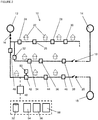
- a portion of an electrical power network 10 is shown.
- a plurality of electrical power supply facilities 12, 13, 14, 15 are connectable to a region 2, 4, 6, 8 of a network to provide electrical power to that region of the network.
- a region 2, 4, 6, 8 comprises a plurality of segments 22, each segment 22 being connectable to one or more neighbouring segments 22 by a respective switching device 24 (also shown as 26, 28, 30, 32, 34, 36, 38, 40, 42, 44, 46 in the Figures).
- the switching devices 24 are operable to connect and disconnect electrical power transmission between the segments 22.
- the switching devices 24 typically remain closed, and thus connected, so that electrical power is transmitted around the region 2, 4, 6, 8.
- Properties sharing a residential street for example, may be powered by a single segment 22 of the network, and neighbouring streets powered by other respective segments 22.
- the electrical power supply facilities 12, 13, 14, 15 are typically electrical substations, for converting electrical power supplied by power stations (including but not limited to thermal power stations using fossil fuels, nuclear power, geothermal power, biomass, or the like, renewable energy power stations including hydroelectric, solar, wind, marine, and osmosis and pumped storage energy providers including pumped-storage hydroelectricity, thermal energy storage, flywheel energy storage and battery storage for example) into a suitable form for consumers to draw from an electrical power transmission network forming the electrical grid.
- the electrical power supply facilities 12, 13, 14, 15 may include primary electrical power supply facilities associated with supplying electricity to the region, including a substation, a power generator, or a power storage apparatus, or any other suitable source of power to an electrical supply grid.
- the voltage is stepped down at the substations, to an appropriate distribution level to be supplied to the population. For example, in the United Kingdom electricity is supplied at 230V alternating current, within an error margin of +10% to -6%, and at 50Hz.
- Each electrical power supply facility 12, 13, 14, 15 is connected to the network via a respective circuit breaker 16 that is operable to disconnect the electrical power supply facility 12, 13, 14, 15 from the network in response to a fault condition.
- the fault condition may include an excessive current (i.e. above a pre-defined limit) being detected, caused by a short circuit or ground fault, for example.
- the circuit breaker 16 may trip, disconnecting the electrical power supply facility 12, 13, 14, 15 to avoid or reduce the likelihood of further malfunction or harmful conditions arising.
- the network is typically split into distinct regions 2, 4, 6, 8, each typically being supplied with power from a respective electrical power supply facilities 12, 13, 14, 15. Multiple regions 2, 4, 6, 8 are capable of being connected to each other using network interconnection switches 17, 18, 19, 20, 21, to improve reliability. If a fault occurs or maintenance is required at a first electrical power supply facility 12 in a first region 2, for example, power supply to that region 2 is disrupted. Power may be supplied from an alternative electrical power supply facility 13, 14, 15 situated in another region 4, 6, 8, by connecting its respective network interconnection switch 17, 18, 19, 20, 21. In this way, power supply to the region 2 may be maintained with minimal impact to energy consumers.
- a control system is associated with the network, which is used to oversee the functioning of the network.
- the control system is configured to carry out monitoring of the performance of the various devices on the network, and to ensure that the network is operated as required.
- the control system provides a controller 48 that is communicatively coupled with the switching devices 24 to 46 so as to operate the switching devices 24 to 46 remotely, via a communication interface 54.
- the communication may be performed via standard communication channels as is known in the art, such as via electrical communications buses, over a wired or wireless network, via satellite communication, or by any other suitable means.
- the controller 48 includes a processing unit 56 comprising one or more processor cores and being operable to execute a plurality of process threads, as is known in the art.
- Multi-threading technology may be used to run threads concurrently so that routines performed by the threads run alongside one another, executing substantially simultaneously. It is known to assign executing threads to one or more distinct cores each, to ensure smooth parallel execution. It is also known to implement one or more virtual cores, to run multiple threads substantially simultaneously using a single core, if required. Any suitable processing unit must be operable to execute multiple threads concurrently.
- the controller 48 is configured to execute a computer program that causes the control system to operate according to the method outlined below.
- control system includes a plurality of communication devices 50 each associated with a respective switching device 42 and/or forming part of the switching device.
- the communication devices 50 are configured to receive communications from the controller 48 to cause the associated switching device 42 to connect or disconnect the electrical power transmission between its associated segments 22.
- Standard FLISR methods involve reconnecting electrical power to segments within a region sequentially - one at a time - until the fault is repeated. At that point, the segment in which the fault has occurred can be identified (as the last segment reconnected to the power supply). That segment can then be isolated (i.e. disconnected from the rest of the region) before the electrical power supply is restored.
- each switching device 24, 26, 28, 30, 32, 34, 36, 38, 40, 42, 44, 46 is operated in turn, so as to reconnect electrical power supply to an unpowered segment 22.
- a delay is provided to determine whether or not a fault has occurred. If a fault has occurred, then the original fault has been found and the segment 22 in which the fault is present has been identified. If not, the next segment in the sequence is reconnected.
- the average time taken to locate the fault is therefore in the order of N/2, where N is the number of segments in the region (i.e. N/2 segments must be reconnected on average, prior to locating the fault).
- the method of fault isolation and electrical power restoration is applicable in general terms, to an electrical network comprising a plurality of electrical power supply facilities 12, 13, 14, 15 connectable to a region 2, 4, 6, 8 of a network to provide electrical power to that region 2, 4, 6, 8 of the network.
- each region 2, 4, 6, 8 provides its own electrical power supply facility 12, 13, 14, 15, and is also connectable to further electrical power supply facilities 12, 13, 14, 15 associated with the other regions, via their respective network interconnection switches 17, 18, 19, 20, 21.
- the electrical power supply facilities connectable to the region might include battery storage facilities, and other sources of electrical power, which may be connected to the grid intermittently when required.
- the region 2, 4, 6, 8 comprises a plurality of segments 22 as described, each segment being 22 connectable to one or more neighbouring segments 22 by a respective switching device 24 to 46 operable to connect and disconnect electrical power transmission between the segments 22.
- the method includes a step of detecting a fault condition within the region 2, 4, 6, 8. This can be achieved via feedback from sensors associated with the network, as is known in the art, detecting unexpected fluctuations in voltage, current or frequency, or the like, or by conditions causing hardware to trip thereby disconnecting power sources from the network.
- the circuit breaker 16 associated with the electrical power supply facility 12 may trip, disconnecting the power from the network, by which the fault condition is detected.
- the method includes operating the plurality of switching devices 24 to 46 connecting the segments 22 within the region so as to disconnect those segments 22 from one another. This step ensures that when the electrical power supply facility 12, 13, 14, 15 is reconnected (or connected via a network interconnect device 17 to 21), power is restored only to a single segment 22 at a time as the result of connecting a single switching device 24 to 46, during each reconnection routine. If some of the switching devices 24 to 46 remain connected, then reconnecting a segment 22 to provide power to that segment 22 may result in multiple adjoining segments 22 also receiving power at the same time. Any subsequent fault detected cannot then be traced to a single one of those segments 22 without carrying out further investigation or analysis.
- the method includes performing a reconnection routine for each of a plurality of reconnection zones, each reconnection zone comprising a distinct plurality of adjoining segments 22 within the region 2, 4, 6, 8.
- Each reconnection zone comprises a segment 22 that is connectable to one of the electrical power supply facilities 12, 13, 14, 15, so that each reconnection zone is associated with a different one of the electrical power supply facilities 12, 13, 14, 15.
- one of the reconnection zones is associated with a primary electrical power supply facility 12 associated with supplying electricity to the region 2 (i.e. the region's usual power supply, such as a local substation).
- the other electrical power supply facilities are one or more secondary facilities, each connectable to the region 2 via a network interconnection switching device 17, 18, 19, 20, 21.
- These secondary facilities may be the primary electrical power supply facilities of one or more other regions, for example.
- the electrical power supply facility to a first region 2 is the first electrical power supply facility 12, and secondary supplies may be provided by second and third electrical power supply facilities 14 and 15, from respective second and third regions 4 and 8, for example, connectable by first and second network interconnect switching devices 18, 20.
- the reconnection routines for each of the reconnection zones are run concurrently, so that the reconnection of power, sequentially, to each reconnection zone is achieved in as short a time as is possible. This ensures that power is restored promptly.
- the controller 48 executes the reconnection routines as threads running concurrently on the one or more processor cores.
- the processing may be distributed across more than one device, or across processing devices on a computer network, for example.
- the reconnection routine involves the following steps:
- a segment 22 On completion of the reconnection routines, a segment 22 has been identified as causing the fault condition. That identified segment 22 is isolated by operating the switching devices 24 to 46 associated with that segment 22 (i.e. any switching device 24 to 46 connecting that segment to any other segment 22) to disconnect that segment 22 from its neighbouring segments 22.
- the switching devices 24 to 46 throughout the rest of the region are reconnected to one or more of the electrical power supply facilities. It may be the case that the primary electrical power supply facility within the region can be connected to all segments 22 other than the isolated segment 22. Otherwise, it one or more 'healthy' segments 22 may not be connectable to the primary electrical power supply facility due to the layout of the network within that region 2, 4, 6, 8, since those segments 22 are only connectable to that supply via the isolated segment 22. In that case, one or more network interconnect switching devices 17, 18, 19, 20, 21 may be connected so that power is provided from one or more of the respective secondary electrical power supply facilities (i.e. from the other regions).
- the method includes a step of operating the all of the switching devices 24 to 46 within the region 2, 4, 6, 8, so as to disconnect the segments within the region 2, 4, 6, 8 from one another prior to performing the reconnection routines.
- the reconnection routines need only operate the switching devices 24 to 46 to connect segments 22, rather than also having to consider disconnecting segments 22 during the process to avoid multiple segments 22 being reconnected to power during a single operation.
- the method includes identifying a test subset of the segments 22 within the region within which test subset the fault has occurred. This may be possible where fault-logging and analytical equipment is used to monitor the status of various parts of the network. As the fault occurs, and power is shut down, signs may be detected that indicate an approximate location of the fault. In that case, disconnecting power from the entire region may be unnecessary, and a subset of known 'healthy' segments may remain powered. The reconnection routines may be run solely on the subset of segments 22 which are not determined to be healthy, and in one of which the fault is likely to lie. In such a scenario, the step of operating the plurality of switching devices connecting the segments so as to disconnect those segments from one another is performed on segments within the test subset.
- the controller 48 determines the plurality of reconnection zones and stores data representative of the segments 22 included in each reconnection zone.
- the data may be stored in a memory 58 or on a storage device 52 associated with the controller 48, for example.
- the plurality of reconnection zones is determined prior to detecting a fault condition within the region. It should also be noted that the order of selection of segments 22 in 'step a' of the reconnection routine may be predetermined and stored with the data defining the reconnection zones, so that, when the routine executes, 'step a' involves selecting the next segment 22 stored in a list.
- a command is sent from the controller 48 to the respective switching device, via its associated communication device 50.
- the switching device then operates to connect or to disconnect the switch, accordingly.
- a signal is sent from the switching device via its associated communication device 50 back to the controller 48, to confirm that the switching action is complete. Therefore, given the two-way communication and time taken to physically alter the status of the switching device, a certain time delay is incurred with each switching action.
- the reconnection routines are carried out, in addition to the delay for instructing the closing of switching devices (i.e. to connect neighbouring segments 22), a further delay is incurred in determining whether a fault condition has occurred.
- a fault may not occur immediately as power is supplied to the segment containing the fault, and therefore a set amount of time is allowed to lapse before an assumption is made that the segment 22 does not contain the fault.
- N segments When N segments are present in a region, it would previously have taken a length of time proportional to N / 2 , on average, to determine the location of a fault and isolate the identified segment. Following the method of the present invention, that average time is reduced to a time proportional to N / 2R, on average, where R is the number of reconnection zones implemented (which is limited by the number of network interconnect switching devices 17, 18, 19, 20, 21 joining other regions 4, 6, 8 to the target region 2).
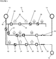
- Figure 2 depicts a first region 2 of a network in which a first electrical power supply facility 12 is located, and connected to the region 2 via a circuit breaker 16.
- the segments 22 (depicted by houses, but which of course may contain any variety or combination of equipment and/or buildings whether industrial, residential, commercial, or for any other purpose) are connected to the first electrical power supply facility 12 via a plurality of switching devices 24 to 46.
- Neighbouring regions 4, 8 provide second and third respective electrical power supply facilities 14, 15. Those facilities, which are secondary electrical power supply facilities to the first region 2, can be connected to the region 2 via respective network interconnection switching devices 18, 20.
- Figure 3 illustrates the occurrence of a fault in the first region 2, in the segment defined between switching devices labelled 34 and 36.
- the fault triggers the circuit breaker 16 to trip, disconnecting the supply to the network.
- Each segment 22 within the region is shown to be disconnected from the power supply.
- the region 2 is divided into three reconnection zones.
- the first comprises the segments 22 defined between switching devices 24, 26, 28, 30 along the uppermost row in the illustration, and is connectable to the first electrical power supply facility 12.
- the second comprises the segments defined between switching devices 32, 34, 36 and 38, along the middle row in the illustration, and is connectable to the second electrical power supply facility 14.
- the third comprises the segments defined between switching devices 40, 42, 44 and 46, along the lowermost row of the illustration, and is connectable to the third electrical power supply facility 15.
- All of the switching devices 24 to 46 within the region are disconnected, according to a preferred embodiment, as described above.
- the circuit breaker 16 is reset, and the first and second network interconnection switching devices 18, 20 are closed so as to connect the second and third electrical power supply facilities 14, 15 to their respective reconnection zones.
- a reconnection routine is performed in relation to each of the three reconnection zones.
- a zone is selected from those that are unpowered (i.e. all of them at this stage), and from those connectable to the respective source of power in that zone.
- Switching devices 24, 38, 46 are then operated to connect their associated segments to the power sources, as illustrated in Figure 4 .
- a delay occurs as the control system determines whether a fault has occurred within any one of the reconnection zones. Since it has not, the steps are repeated.
- the segment identified as causing the fault condition is isolated, by operating the switching devices 34, 36 to disconnect that segment from its neighbouring segments. Once that segment has been isolated, the switching devices throughout the rest of the region 2 are operated to reconnect the segments 22 within the region to an electrical power supply facility 12, 14, excluding the identified isolated segment. As shown in Figure 6 , one or more segments 22 may be connected via a network interconnection switching device 18 to an electrical power supply facility 14 in a neighbouring region 4, for example.
Landscapes
- Engineering & Computer Science (AREA)
- Power Engineering (AREA)
- Remote Monitoring And Control Of Power-Distribution Networks (AREA)
- Supply And Distribution Of Alternating Current (AREA)
- Monitoring And Testing Of Transmission In General (AREA)
Priority Applications (4)
| Application Number | Priority Date | Filing Date | Title |
|---|---|---|---|
| EP17200688.4A EP3484004A1 (fr) | 2017-11-08 | 2017-11-08 | Système de commande et procédé de localisation de défaut, d'isolation et de restauration d'alimentation |
| PCT/EP2018/078455 WO2019091737A1 (fr) | 2017-11-08 | 2018-10-17 | Système de commande et procédé de localisation de défaillances, d'isolation et de restauration d'alimentation |
| US16/761,466 US11309699B2 (en) | 2017-11-08 | 2018-10-17 | Control system for and method of fault location, isolation and supply restoration |
| AU2018363059A AU2018363059B2 (en) | 2017-11-08 | 2018-10-17 | Control system for and method of fault location, isolation and supply restoration |
Applications Claiming Priority (1)
| Application Number | Priority Date | Filing Date | Title |
|---|---|---|---|
| EP17200688.4A EP3484004A1 (fr) | 2017-11-08 | 2017-11-08 | Système de commande et procédé de localisation de défaut, d'isolation et de restauration d'alimentation |
Publications (1)
| Publication Number | Publication Date |
|---|---|
| EP3484004A1 true EP3484004A1 (fr) | 2019-05-15 |
Family
ID=60320661
Family Applications (1)
| Application Number | Title | Priority Date | Filing Date |
|---|---|---|---|
| EP17200688.4A Pending EP3484004A1 (fr) | 2017-11-08 | 2017-11-08 | Système de commande et procédé de localisation de défaut, d'isolation et de restauration d'alimentation |
Country Status (4)
| Country | Link |
|---|---|
| US (1) | US11309699B2 (fr) |
| EP (1) | EP3484004A1 (fr) |
| AU (1) | AU2018363059B2 (fr) |
| WO (1) | WO2019091737A1 (fr) |
Cited By (1)
| Publication number | Priority date | Publication date | Assignee | Title |
|---|---|---|---|---|
| CN114270650A (zh) * | 2019-08-28 | 2022-04-01 | Abb瑞士股份有限公司 | 故障绝缘馈线的修复 |
Families Citing this family (4)
| Publication number | Priority date | Publication date | Assignee | Title |
|---|---|---|---|---|
| JP7018049B2 (ja) * | 2019-01-18 | 2022-02-09 | ダイキン工業株式会社 | 環境制御システム、空気調和機または空気調和システム |
| JP7563584B2 (ja) * | 2021-04-30 | 2024-10-08 | 日本電信電話株式会社 | 短絡保護システム、短絡保護装置、短絡保護方法およびプログラム |
| CN113721103B (zh) * | 2021-11-01 | 2022-02-11 | 广东电网有限责任公司东莞供电局 | 一种高压开关柜在线故障诊断方法及系统 |
| GB202319366D0 (en) * | 2023-12-18 | 2024-01-31 | Rolls Royce Plc | Electrical power systems and methods |
Citations (3)
| Publication number | Priority date | Publication date | Assignee | Title |
|---|---|---|---|---|
| EP2056424A2 (fr) * | 2007-10-30 | 2009-05-06 | General Electric Company | Système et procédé de contrôle des réseaux de distribution électrique |
| US20120203479A1 (en) * | 2011-02-07 | 2012-08-09 | Cisco Technology, Inc. | Fast fault isolation and restoration for distribution networks |
| EP2757648A2 (fr) * | 2013-01-18 | 2014-07-23 | General Electric Company | Procédés et systèmes pour la restauration de la puissance sur la base des charges prévisionnelles |
Family Cites Families (7)
| Publication number | Priority date | Publication date | Assignee | Title |
|---|---|---|---|---|
| US6867958B2 (en) | 2000-12-27 | 2005-03-15 | Abb Technology Ag | Loop restoration scheme for distribution feeders |
| US7751166B2 (en) * | 2007-03-16 | 2010-07-06 | Abb Technology Ag | Advanced feeder architecture with automated power restoration |
| CN102273037B (zh) * | 2008-12-31 | 2014-10-29 | Abb研究有限公司 | 混合配电网电力恢复控制 |
| CN102648477B (zh) * | 2009-12-04 | 2016-10-19 | Abb研究有限公司 | 用遗传算法的恢复开关分析 |
| AU2011207540A1 (en) * | 2010-01-19 | 2012-08-09 | S&C Electric Company | Method and apparatus for control of a commodity distribution system |
| US9099858B2 (en) * | 2011-03-31 | 2015-08-04 | General Electric Company | System and method for assuring utility network security and reliability |
| US9553455B2 (en) * | 2012-10-11 | 2017-01-24 | Siemens Aktiengesellschaft | Use of demand response to enable improved power supply restoration planning |
-
2017
- 2017-11-08 EP EP17200688.4A patent/EP3484004A1/fr active Pending
-
2018
- 2018-10-17 US US16/761,466 patent/US11309699B2/en active Active
- 2018-10-17 WO PCT/EP2018/078455 patent/WO2019091737A1/fr not_active Ceased
- 2018-10-17 AU AU2018363059A patent/AU2018363059B2/en active Active
Patent Citations (3)
| Publication number | Priority date | Publication date | Assignee | Title |
|---|---|---|---|---|
| EP2056424A2 (fr) * | 2007-10-30 | 2009-05-06 | General Electric Company | Système et procédé de contrôle des réseaux de distribution électrique |
| US20120203479A1 (en) * | 2011-02-07 | 2012-08-09 | Cisco Technology, Inc. | Fast fault isolation and restoration for distribution networks |
| EP2757648A2 (fr) * | 2013-01-18 | 2014-07-23 | General Electric Company | Procédés et systèmes pour la restauration de la puissance sur la base des charges prévisionnelles |
Non-Patent Citations (1)
| Title |
|---|
| K SEETHALEKSHMI ET AL: "A Synchrophasor Assisted Frequency and Voltage Stability Based Load Shedding Scheme for Self-Healing of Power System", IEEE TRANSACTIONS ON SMART GRID, 1 January 2011 (2011-01-01), pages 221 - 230, XP055478333, Retrieved from the Internet <URL:https://library.e.abb.com/public/b72d2dbc7fb73561c1257abd001d43ae/ESKOM2012%20_Practical_Experience_of_selfhealing_ABB.pdf> DOI: 10.1109/TSG.2011.2113361 * |
Cited By (2)
| Publication number | Priority date | Publication date | Assignee | Title |
|---|---|---|---|---|
| CN114270650A (zh) * | 2019-08-28 | 2022-04-01 | Abb瑞士股份有限公司 | 故障绝缘馈线的修复 |
| CN114270650B (zh) * | 2019-08-28 | 2024-07-23 | Abb瑞士股份有限公司 | 故障绝缘馈线的修复 |
Also Published As
| Publication number | Publication date |
|---|---|
| US11309699B2 (en) | 2022-04-19 |
| US20200295557A1 (en) | 2020-09-17 |
| AU2018363059A1 (en) | 2020-05-07 |
| WO2019091737A1 (fr) | 2019-05-16 |
| AU2018363059B2 (en) | 2023-06-01 |
Similar Documents
| Publication | Publication Date | Title |
|---|---|---|
| AU2018363059B2 (en) | Control system for and method of fault location, isolation and supply restoration | |
| CN110783945B (zh) | 用于定位微电网中相故障的方法 | |
| US11128127B2 (en) | FLISR without communication | |
| CN107394897A (zh) | 一种基于拓扑图的配电网智能自愈方法及系统 | |
| CN106463951B (zh) | 高压或中压变电站中的负荷恢复 | |
| US20220123589A1 (en) | Non-Three-Phase Fault Isolation and Restoration Systems | |
| Wan et al. | Multi‐agent application of substation protection coordination with distributed generators | |
| Sauhats et al. | Two-terminal out-of-step protection for multi-machine grids using synchronised measurements | |
| CN108616114B (zh) | 一种含微网群的配电网分布式分层保护系统及方法 | |
| CN111276929B (zh) | 电力系统故障专家诊断的信息录波方法 | |
| Uluski | Using distribution automation for a self-healing grid | |
| Nair et al. | IEC 61850 enabled automatic bus transfer scheme for primary distribution substations | |
| Lifan et al. | The experiences of decentralized self-healing grid | |
| CN118472937A (zh) | 主配协同的电网供电恢复方法及装置 | |
| US11791622B2 (en) | Time-admittance fault detection and isolation system | |
| JP2022505260A (ja) | 配電ネットワーク上のパワーアイランド検出方法及びシステム | |
| Muka et al. | Genetic algorithm for placement of IEDs for fault location in smart distribution grids | |
| Leite et al. | Real-time closed-loop test to adaptive protection in a smart-grid context | |
| Yinger | Self-healing circuits at southern California Edison | |
| CN113589095A (zh) | 一体化单相接地故障智能识别定位系统及方法 | |
| PÎSLARU-DĂNESCU et al. | Microgrids Smart Structures Used for Back-up Power Supply. | |
| Dissanayaka et al. | Fault management algorithm for voltage feeder automation in electricity distribution | |
| US20250082971A1 (en) | Advanced wildfire ignition prevention and notification | |
| Sutradhar et al. | A Proposal on Self-Healing Control Strategy for Smart Grid Protection Using Auto-Recloser | |
| Rasmussen | A real case of self healing distribution network |
Legal Events
| Date | Code | Title | Description |
|---|---|---|---|
| PUAI | Public reference made under article 153(3) epc to a published international application that has entered the european phase |
Free format text: ORIGINAL CODE: 0009012 |
|
| STAA | Information on the status of an ep patent application or granted ep patent |
Free format text: STATUS: THE APPLICATION HAS BEEN PUBLISHED |
|
| AK | Designated contracting states |
Kind code of ref document: A1 Designated state(s): AL AT BE BG CH CY CZ DE DK EE ES FI FR GB GR HR HU IE IS IT LI LT LU LV MC MK MT NL NO PL PT RO RS SE SI SK SM TR |
|
| AX | Request for extension of the european patent |
Extension state: BA ME |
|
| STAA | Information on the status of an ep patent application or granted ep patent |
Free format text: STATUS: REQUEST FOR EXAMINATION WAS MADE |
|
| 17P | Request for examination filed |
Effective date: 20191115 |
|
| RBV | Designated contracting states (corrected) |
Designated state(s): AL AT BE BG CH CY CZ DE DK EE ES FI FR GB GR HR HU IE IS IT LI LT LU LV MC MK MT NL NO PL PT RO RS SE SI SK SM TR |
|
| RAP1 | Party data changed (applicant data changed or rights of an application transferred) |
Owner name: ELECTRICITY NORTH WEST PROPERTY LIMITED |
|
| STAA | Information on the status of an ep patent application or granted ep patent |
Free format text: STATUS: EXAMINATION IS IN PROGRESS |
|
| 17Q | First examination report despatched |
Effective date: 20210921 |