EP3485105B1 - Abgehängte decke mit mitteln zum verkeilen von platte(n) und verfahren zur herstellung solch einer abgehängten decke - Google Patents
Abgehängte decke mit mitteln zum verkeilen von platte(n) und verfahren zur herstellung solch einer abgehängten decke Download PDFInfo
- Publication number
- EP3485105B1 EP3485105B1 EP17745437.8A EP17745437A EP3485105B1 EP 3485105 B1 EP3485105 B1 EP 3485105B1 EP 17745437 A EP17745437 A EP 17745437A EP 3485105 B1 EP3485105 B1 EP 3485105B1
- Authority
- EP
- European Patent Office
- Prior art keywords
- panel
- profiles
- ceiling
- profile
- wedging
- Prior art date
- Legal status (The legal status is an assumption and is not a legal conclusion. Google has not performed a legal analysis and makes no representation as to the accuracy of the status listed.)
- Active
Links
Images
Classifications
-
- E—FIXED CONSTRUCTIONS
- E04—BUILDING
- E04B—GENERAL BUILDING CONSTRUCTIONS; WALLS, e.g. PARTITIONS; ROOFS; FLOORS; CEILINGS; INSULATION OR OTHER PROTECTION OF BUILDINGS
- E04B9/00—Ceilings; Construction of ceilings, e.g. false ceilings; Ceiling construction with regard to insulation
- E04B9/22—Connection of slabs, panels, sheets or the like to the supporting construction
- E04B9/24—Connection of slabs, panels, sheets or the like to the supporting construction with the slabs, panels, sheets or the like positioned on the upperside of, or held against the underside of the horizontal flanges of the supporting construction or accessory means connected thereto
- E04B9/241—Connection of slabs, panels, sheets or the like to the supporting construction with the slabs, panels, sheets or the like positioned on the upperside of, or held against the underside of the horizontal flanges of the supporting construction or accessory means connected thereto with the slabs, panels, sheets or the like positioned on the upperside of the horizontal flanges of the supporting construction
- E04B9/242—Connection of slabs, panels, sheets or the like to the supporting construction with the slabs, panels, sheets or the like positioned on the upperside of, or held against the underside of the horizontal flanges of the supporting construction or accessory means connected thereto with the slabs, panels, sheets or the like positioned on the upperside of the horizontal flanges of the supporting construction with separate retaining elements
-
- E—FIXED CONSTRUCTIONS
- E04—BUILDING
- E04B—GENERAL BUILDING CONSTRUCTIONS; WALLS, e.g. PARTITIONS; ROOFS; FLOORS; CEILINGS; INSULATION OR OTHER PROTECTION OF BUILDINGS
- E04B9/00—Ceilings; Construction of ceilings, e.g. false ceilings; Ceiling construction with regard to insulation
- E04B9/006—Ceilings; Construction of ceilings, e.g. false ceilings; Ceiling construction with regard to insulation with means for hanging lighting fixtures or other appliances to the framework of the ceiling
-
- E—FIXED CONSTRUCTIONS
- E04—BUILDING
- E04B—GENERAL BUILDING CONSTRUCTIONS; WALLS, e.g. PARTITIONS; ROOFS; FLOORS; CEILINGS; INSULATION OR OTHER PROTECTION OF BUILDINGS
- E04B9/00—Ceilings; Construction of ceilings, e.g. false ceilings; Ceiling construction with regard to insulation
- E04B9/04—Ceilings; Construction of ceilings, e.g. false ceilings; Ceiling construction with regard to insulation comprising slabs, panels, sheets or the like
-
- E—FIXED CONSTRUCTIONS
- E04—BUILDING
- E04B—GENERAL BUILDING CONSTRUCTIONS; WALLS, e.g. PARTITIONS; ROOFS; FLOORS; CEILINGS; INSULATION OR OTHER PROTECTION OF BUILDINGS
- E04B9/00—Ceilings; Construction of ceilings, e.g. false ceilings; Ceiling construction with regard to insulation
- E04B9/18—Means for suspending the supporting construction
-
- E—FIXED CONSTRUCTIONS
- E04—BUILDING
- E04B—GENERAL BUILDING CONSTRUCTIONS; WALLS, e.g. PARTITIONS; ROOFS; FLOORS; CEILINGS; INSULATION OR OTHER PROTECTION OF BUILDINGS
- E04B9/00—Ceilings; Construction of ceilings, e.g. false ceilings; Ceiling construction with regard to insulation
- E04B9/04—Ceilings; Construction of ceilings, e.g. false ceilings; Ceiling construction with regard to insulation comprising slabs, panels, sheets or the like
- E04B2009/0492—Ceilings; Construction of ceilings, e.g. false ceilings; Ceiling construction with regard to insulation comprising slabs, panels, sheets or the like with fabrics tensioned on frames
Definitions
- the invention relates to the field of false walls, and in particular that of suspended false ceilings.
- the invention relates more particularly to a false ceiling comprising a load-bearing structure capable of carrying a stretched canvas and at least one panel such as a light panel.
- the suspended suspended ceilings are made in the classic way using rails and removable flat slabs carrying a stretched canvas. More specifically, rows of rails are arranged in two perpendicular directions so as to define a grid. The slabs are placed resting on the rails, between each of the rows of the rails.
- the ceilings are already provided with a structure in the form of parallel and opposite rails equidistant for the fixing of technical elements or their passage.
- the production of a false ceiling, and in particular the installation of the rails intended to support the panels or slabs, is then constrained by the presence of the existing rails as well as by the transverse distance separating the latter from one another. It is therefore necessary to come and fix the profiles intended to receive the canvas stretched on the existing rails beforehand in order to then fix the canvas on the latter and thus form the slab.
- a false ceiling comprising a panel fixed to two rail bodies by means of elastic retaining profiles.
- Each retaining section comprises means for hooking onto one of the stringer bodies as well as an elastic arm exerting a thrust on the panel such that the panel is kept pressed against a bearing zone of the stringer body.
- the invention aims to remedy these problems by proposing a false ceiling and an installation method making it possible to solve the problems referred to above.
- the object of the invention is to provide a false ceiling offering rapid, easy and safe installation and removal of a panel while limiting the shadow cast on the canvas when the panel is a light panel.
- the invention provides a false ceiling according to the subject of claim 1.
- the panels are held on the shoulders by simple gravity, while being prevented from falling due to improper handling of the latter or their displacement with respect to the profiles, and whatever or the dimensions of the shoulders on which the panels rest.
- the wedging means can also have the advantage of ensuring a centered positioning of the panels relative to the profiles.
- the wedging means are placed in vertical support on the bearing surfaces of the profiles.
- Each wedging means is interposed transversely between a lateral edge of the panel and a vertical bearing face of an associated profile oriented towards the opposite profile.
- the wedging means have a nominal transverse width established as a function of the width of the panel and the width of the access opening to the ceiling so as to prevent a transverse displacement of the panel such that one of the side edges of the panel comes. position themselves facing the passage opening, the panel having a width greater than the width of the ceiling access opening.
- the wedging means are thus arranged to prevent transverse movement of the panel on the profiles, apart from a clearance necessary to allow rapid positioning of the panel on the profiles and their removal by simple pushing.
- Each wedging means is a wedging bar, the elongate body of which rests vertically along a bearing surface of an associated section, and which is interposed transversely between a lateral edge of the panel and a vertical bearing face of the associated profile oriented towards the opposite profile.
- the wedging bar comprises at least one elongated flat lower face capable of being supported along a bearing surface of an associated section.
- the wedging bar has a rectangular or square cross section so as to include two opposite elongate flat side walls capable of being interposed transversely between a side edge of the panel and a vertical bearing face of the associated profile oriented towards the opposite profile.
- the shoulders of the profiles define a bearing surface having a transverse width greater than or equal to 5 millimeters so as to limit the shadow cast on the canvas placed under the panel when the latter is a light panel while ensuring the maintenance of the panel via the presence of the locking means.
- the bearing surfaces of the profiles are located at the same height.
- the profiles, of triangular section include a notch formed in the upper part, the intersection of two faces of the notch defining the shoulder.
- the panel comprises light means.
- the false ceiling comprises a stretched canvas fixed in the lower part of the profiles, extending parallel to the panel.
- the invention also relates to a method according to claim 9 for installing a panel on a ceiling provided with an existing structure for producing a false ceiling.
- the method comprises a step d) consisting in placing at least one other removable wedging means attached to a bearing surface of the other of the profiles.
- transverse orientation will be designated corresponding substantially to the horizontal orientation of the panel in position, and the longitudinal orientation in the horizontal direction orthogonal to the plane of the figures.
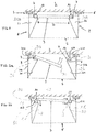
- a false ceiling 1 comprising a supporting structure 2, at least one panel 3, advantageously luminous, a stretched fabric 5 and means for wedging the panel 3 on the supporting structure 2.
- the supporting structure 2 comprises a series of sections 20, 21 parallel to each other, and preferably equidistant from each other, fixed to a ceiling 4. In the example illustrated, only two transversely opposed sections 20, 21 are shown.
- the profiles 20, 21 are fixed to the ceiling 4 via rails 6 carried by the ceiling 4. As will be seen later, during the description of the installation of the light panel 3, these rails fall under an existing structure of the ceiling. .
- the profiles 20, 21 are coplanar and extend parallel to one another. They are symmetrical with respect to one another and are arranged between them so as to define an access opening to the ceiling 4 of transverse width "D".
- each section 20, 21, of triangular section has a horizontal upper surface 200, 210, the other two surfaces defining an internal surface 201, 211 inclined and a vertical external surface 202, 212 of the structure. carrier 2.
- internal surface of a section 20, 21 is meant the surface oriented on the side of the access opening and facing the other opposite section, and by external surface, the surface opposite to the internal surface.
- each profile 20, 21 comprises a notch 7 at right angles, extending along the profile 20, 21.
- the notch 7 extends over the entire length of the profile 20, 21.
- the notch 7 thus takes the form of a longitudinal groove with a right-angled section similar to an "L" profile.
- each profile 20, 21 has a notch 7 arranged to define a shoulder having a horizontal bearing surface 8 defining a horizontal bearing plane oriented towards the ceiling 4.
- the bearing surfaces 8 of each of the profiles 20, 21 extend in the same plane parallel to the plane of the ceiling 4.
- the panel 3 is sized to rest on the horizontal bearing surface 8 of each section 20, 21.
- it has a transverse width greater than the transverse width "D" of the ceiling access opening. , which, in the illustrated embodiment, corresponds to the distance D separating the free edges facing the shoulders.
- each shoulder has a horizontal bearing surface having a width greater than or equal to 5 millimeters.
- This has the advantage of limiting the shadow cast on the canvas 5 when the panel 3 carried by the profiles 20, 21 is a light panel. Given the narrowness of the shoulders, the panel 3 rests on them for only a few millimeters.
- wedging means 10 are placed on the shoulder of each of the profiles. 20, 21, between a lateral edge 30 of the panel 3 and a vertical stop face 9 delimiting the notch 7.
- each notch 7 is delimited by a horizontal support surface 8, and a vertical support or stop surface 9.
- each wedging means 10 consists of an elongated wedging bar 10A, 10B.
- Each wedging bar is for example an elongated rectilinear bar of rectangular or square section.
- the wedging means 10 are appropriately sized.
- Each wedging bar 10A, 10B is thus a removable insert component which can be placed in an associated notch 7.
- each wedging bar comprises at least one flat lower surface 11 which is able to rest vertically on an associated horizontal support surface 8.
- Each wedging bar is also delimited by two opposite vertical side faces 12 and 13.
- the external vertical side face In position in a notch 7, and after mounting the panel 3, the external vertical side face is opposite or in contact with a vertical surface 9, while the internal vertical face 13 is opposite or in contact with a side edge 30 of the panel 3.
- the installation of the panel 3 on the supporting structure 2 is carried out as follows (the movements implemented for the purposes of installing the panel 3 are represented by arrows in solid lines).
- first wedging means constituted by a first wedging bar 10A are installed in the notch 7 of one 21 of the profiles 20, 21, on the corresponding horizontal bearing surface 8 louse associated.
- the panel 3 is then inserted into the space delimited between the ceiling 4 and the supporting structure 2 through the access opening, being introduced and placed at an angle as illustrated in figure 2a .
- the installer can have a set of wedging means in the form for example of a set of wedging bars, possibly of different dimensions (length and cross section) that it implements according to the method described above.
- each panel 3 can be formed by several elements, for example tiles, adjacent, but all of the same transverse width.
- each wedging bar can be in a single piece over the entire necessary length, or in several elements placed adjacent and in the extension. longitudinal from each other.
Landscapes
- Engineering & Computer Science (AREA)
- Architecture (AREA)
- Physics & Mathematics (AREA)
- Electromagnetism (AREA)
- Civil Engineering (AREA)
- Structural Engineering (AREA)
- Finishing Walls (AREA)
- Building Environments (AREA)
- Non-Portable Lighting Devices Or Systems Thereof (AREA)
Claims (11)
- Zwischendecke (1), umfassend eine Tragstruktur (2), die mindestens zwei koplanare und zueinander parallele gegenüberliegende Profile (20, 21) aufweist, die an einer Decke (4) befestigt sind, wobei diese Profile untereinander eine Zugangsöffnung (D) zur Decke definieren, wobei jedes Profil (20, 21) eine Schulter umfasst, die eine horizontale Auflageoberfläche (8) definiert, die zur Decke (4) hin gerichtet ist, mindestens eine Platte (3), die zwischen den Profilen (20, 21) angeordnet ist, wobei die Platte (3) so dimensioniert ist, dass sie auf der Auflageoberfläche (8) der Profile (20, 21) ruht, wobei die Zwischendecke ferner abnehmbare und angebaute Mittel (10) zum quergerichteten Unterfüttern der Platte (3) zwischen zwei gegenüberliegenden Profilen (20, 21) aufweist, wobei die Unterfütterungsmittel (10) auf beiden Seiten der Platte (3) eingerichtet sind, so dass jedes Unterfütterungsmittel
(10) ein Unterfütterungsstab (10A, 10B) ist, dessen länglicher Körper vertikal entlang einer Auflageoberfläche (8) eines zugehörigen Profils (21, 20) aufliegt, und quer zwischen einer Seitenkante (30) der Platte und einer vertikalen, zum gegenüberliegenden Profil (21, 20) hin gerichteten Auflagefläche (9) des zugehörigen Profils (21, 20) eingefügt ist, und so dass die Platte (3) eine Breite vorweist, die größer ist als die Breite der Zugangsöffnung, und die Unterfütterungsmittel (10) eine nominelle Querbreite vorweisen, die in Abhängigkeit von der Breite der Platte (3) und der Breite der Zugangsöffnung festgelegt ist, um mit der Platte (3) ein Spiel zu definieren, das es ermöglicht, diese auf die Profile (20, 21) zu setzen, und sie durch einfaches Schieben zurückzuziehen, wobei eine Querverschiebung der Platte (3) verhindert wird, so dass eine der Seitenkanten (30) der Platte (3) gegenüber der Zugangsöffnung positioniert wird, wobei die Platte (3) durch einfache Schwerkraft auf den Schultern gehalten wird. - Zwischendecke nach Anspruch 1, dadurch gekennzeichnet, dass der Unterfütterungsstab (10A, 10B) mindestens eine längliche ebene Unterseite (11) aufweist, die geeignet ist, entlang einer Auflageoberfläche (8) eines zugehörigen Profils (21, 20) aufzuliegen.
- Zwischendecke nach Anspruch 2, dadurch gekennzeichnet, dass der Unterfütterungsstab (10A, 10B) im Querschnitt rechteckig oder quadratisch ist, so dass er zwei gegenüberliegende längliche ebene Seitenwände (12, 13) aufweist, die geeignet sind, quer zwischen einer Seitenkante (30) der Platte und einer vertikalen Auflagefläche (9) des zugehörigen Profils eingefügt zu werden, die zum gegenüberliegenden Profil hin ausgerichtet ist.
- Zwischendecke (1) nach einem der vorhergehenden Ansprüche, dadurch gekennzeichnet, dass die Schultern der Profile (20, 21) eine Auflageoberfläche (8) definieren, die eine Querbreite größer oder gleich 5 Millimeter vorweist.
- Zwischendecke (1) nach einem der vorhergehenden Ansprüche, dadurch gekennzeichnet, dass die Auflageoberflächen (8) der Profile (20, 21) auf der gleichen Höhe gelegen sind.
- Zwischendecke (1) nach einem der vorhergehenden Ansprüche, dadurch gekennzeichnet, dass die Profile (20, 21) mit dreieckigem Querschnitt eine im oberen Teil vorgesehene Kerbe aufweisen, wobei der Schnittpunkt zweier Flächen der Kerbe die Schulter definiert.
- Zwischendecke (1) nach einem der vorhergehenden Ansprüche, dadurch gekennzeichnet, dass die Platte (3) Beleuchtungsmittel aufweist.
- Zwischendecke (1) nach einem der vorhergehenden Ansprüche, dadurch gekennzeichnet, dass sie ein gespanntes Tuch (5) aufweist, das am unteren Teil der Profile (20, 21) befestigt ist und sich parallel zur Platte (3) erstreckt.
- Verfahren zum Anbringen einer Platte (3) an einer Decke (4), die mit einer vorhandenen Struktur zur Realisierung einer Zwischendecke (1) versehen ist, wobei die vorhandene Struktur mindestens zwei gegenüberliegende Schienen (6) umfasst, die koplanar und parallel zueinander sind, wobei das Verfahren die folgenden Schritte umfasst:a) Befestigen eines Profils (20, 21) an jeder Schiene (6), wobei jedes Profil mit dem an einer gegenüberliegenden Schiene befestigten Profil (21, 20) eine Zugangsöffnung (7) zur Decke (4) definiert, wobei jedes Profil (20, 21) eine Schulter umfasst, die eine horizontale, zur Decke (4) hin gerichtete Auflageoberfläche (8) definiert,b) schräges Einsetzen einer Platte (3), die einen Querschnitt vorweist, der größer ist als die Breite (D) der Zugangsöffnung (7), in den über den Profilen (20, 21) gelegenen und von der Decke (4) begrenzten Raum,c) Platzieren mindestens eines abnehmbaren Unterfütterungsmittels (10A), das an einer Auflageoberfläche (8) eines (21) der Profile (20, 21) angebaut ist, wobei das Unterfütterungsmittel (10) ein Unterfütterungsstab (10A, 10B) ist, dessen länglicher Körper vertikal entlang einer Auflageoberfläche (8) eines zugehörigen Profils (21, 20) aufliegt, und der quer zwischen einer Seitenkante (30) der Platte und einer vertikalen, zum gegenüberliegenden Profil (20, 21) hin gerichteten Auflagefläche (9) des zugehörigen Profils (21, 20) eingefügt ist,d) um die Platte (3) auf den Auflageoberflächen zu positionieren, wobei die Unterfütterungsmittel eine quer verlaufende Nennbreite vorweisen, die in Abhängigkeit von der Breite der Platte (3) und der Breite der Zugangsöffnung festgelegt ist, um ein Spiel zu definieren, das es ermöglicht, diese auf die Profile (20, 21) zu setzen und durch einfaches Schieben zurückzuziehen, wobei eine Querverschiebung der Platte (3) verhindert wird, so dass eine der Seitenkanten (30) der Platte (3) gegenüber der Zugangsöffnung positioniert wird, wobei die Platte (3) durch einfache Schwerkraft auf den Auflageoberflächen gehalten wird.
- Verfahren nach Anspruch 9, dadurch gekennzeichnet, dass der Schritt c) des Platzierens vor oder nach dem Schritt b) des Einsetzens durchgeführt wird.
- Verfahren nach einem der Ansprüche 9 oder 10, dadurch gekennzeichnet, dass es einen Schritt e) aufweist, der darin besteht, mindestens ein weiteres abnehmbares Unterfütterungsmittel (10B) zu platzieren, das an einer Auflageoberfläche (8) des anderen (20) der Profile (20, 21) angebaut ist.
Applications Claiming Priority (2)
| Application Number | Priority Date | Filing Date | Title |
|---|---|---|---|
| FR1656753A FR3053987B1 (fr) | 2016-07-13 | 2016-07-13 | Faux-plafond comprenant des moyens de calage de panneaux et procede pour la realisation d'un tel faux-plafond |
| PCT/FR2017/051933 WO2018011530A1 (fr) | 2016-07-13 | 2017-07-13 | Faux-plafond comprenant des moyens de calage de panneau(x) et procede pour la realisation d'un tel faux-plafond |
Publications (2)
| Publication Number | Publication Date |
|---|---|
| EP3485105A1 EP3485105A1 (de) | 2019-05-22 |
| EP3485105B1 true EP3485105B1 (de) | 2021-09-01 |
Family
ID=57121324
Family Applications (1)
| Application Number | Title | Priority Date | Filing Date |
|---|---|---|---|
| EP17745437.8A Active EP3485105B1 (de) | 2016-07-13 | 2017-07-13 | Abgehängte decke mit mitteln zum verkeilen von platte(n) und verfahren zur herstellung solch einer abgehängten decke |
Country Status (4)
| Country | Link |
|---|---|
| US (1) | US10738468B2 (de) |
| EP (1) | EP3485105B1 (de) |
| FR (1) | FR3053987B1 (de) |
| WO (1) | WO2018011530A1 (de) |
Families Citing this family (1)
| Publication number | Priority date | Publication date | Assignee | Title |
|---|---|---|---|---|
| FR3108641B1 (fr) * | 2020-03-24 | 2022-04-15 | Normalu | Profilé de cadre pour la réalisation d’une fausse paroi rétroéclairée et une telle fausse paroi rétroéclairée |
Family Cites Families (6)
| Publication number | Priority date | Publication date | Assignee | Title |
|---|---|---|---|---|
| US4769965A (en) * | 1987-11-27 | 1988-09-13 | Armstrong World Industries, Inc. | Method and apparatus of positioning a new ceiling over an existing ceiling |
| DE9109410U1 (de) * | 1991-07-30 | 1991-09-19 | Promat GmbH, 40878 Ratingen | Unterdecke für Brandschutzzwecke |
| US5782551A (en) * | 1994-11-01 | 1998-07-21 | Capaul; Raymond W. | Acoustical lighting fixture |
| FR2892739B1 (fr) | 2005-11-03 | 2008-01-18 | Newmat Sa Sa | Profil pour cadre a empocher |
| FR3002566B1 (fr) * | 2013-02-27 | 2018-02-16 | Newmat | Profile en fleche pour la constitution d'un cadre de dalle de faux plafond ou de faux mur |
| DE102014113059A1 (de) * | 2014-09-10 | 2016-03-10 | Schilling Engineering GmbH | Deckenprofil |
-
2016
- 2016-07-13 FR FR1656753A patent/FR3053987B1/fr active Active
-
2017
- 2017-07-13 EP EP17745437.8A patent/EP3485105B1/de active Active
- 2017-07-13 US US16/317,255 patent/US10738468B2/en active Active
- 2017-07-13 WO PCT/FR2017/051933 patent/WO2018011530A1/fr not_active Ceased
Also Published As
| Publication number | Publication date |
|---|---|
| FR3053987B1 (fr) | 2021-06-18 |
| US20190292782A1 (en) | 2019-09-26 |
| US10738468B2 (en) | 2020-08-11 |
| WO2018011530A1 (fr) | 2018-01-18 |
| FR3053987A1 (fr) | 2018-01-19 |
| EP3485105A1 (de) | 2019-05-22 |
Similar Documents
| Publication | Publication Date | Title |
|---|---|---|
| FR3054862A3 (fr) | Agrafe de maintien de deux elements plans | |
| FR2975573A1 (fr) | Element profile pour des meubles, notamment des etageres | |
| FR3074206A1 (fr) | Dispositif de fixation de lamelles a panneau grillage rigide, kit de fixation de lamelles a panneau grillage rigide et cloture occultante equipee d’un tel kit | |
| WO2018011530A1 (fr) | Faux-plafond comprenant des moyens de calage de panneau(x) et procede pour la realisation d'un tel faux-plafond | |
| EP2573888A1 (de) | Clip für Kabelpritsche | |
| EP1567731B1 (de) | Bausatz mit einem Parkettstab und einen Befestigungsbeschlag hierfür | |
| FR3078086A1 (fr) | Systeme de platelage comportant des moyens de fixation d'un bandeau peripherique vertical. | |
| FR2922237A1 (fr) | Attache pour panneaux de faux-plafonds. | |
| FR2987421A1 (fr) | Patte d'accrochage d'elements d'isolation. | |
| FR2986252A1 (fr) | Dispositif et procede de pose d'un materiau de parement en vrac, tel que les pierres, a une face d'au moins un ouvrage, tel qu'un mur en beton | |
| FR3029550A1 (fr) | Dispositif de montage provisoire d'elements sur une poutre de structure de batiment | |
| FR3057290A1 (fr) | Systeme de coffrage, organe de liaison specialement adapte pour un tel systeme de coffrage et procede de realisation d'une dalle d'un batiment mettant en œuvre un tel systeme de coffrage | |
| FR2920798A1 (fr) | Plafond suspendu | |
| BE1012517A3 (fr) | Procede et dispositif pour la consolidation d'un parement de mur. | |
| FR3058430A1 (fr) | Element de construction prefabrique | |
| FR2797901A1 (fr) | Procede et dispositif pour fixer des panneaux sur un support | |
| EP2264255B1 (de) | Trennwandstruktur, insbesondere einer Hohltrennwand | |
| FR3033689A1 (fr) | Dispositif support de tringles, adaptable sur la face avant de caissons de volets roulants. | |
| FR3056999A1 (fr) | Dalle pour la fixation a une ossature de plafond suspendu, plafond suspendu comportant une telle dalle et procede de fixation de la dalle | |
| WO2019243737A1 (fr) | Procédé de réalisation d'un parement | |
| WO2016108025A1 (fr) | Procédé d'isolation, suspente et ensemble associés | |
| FR2981963A1 (fr) | Installation pour bardage de facade | |
| FR3135101A1 (fr) | Connecteur | |
| EP2405066A1 (de) | Stahlskelett eines Hauses, Eckpfosten dieses Hauses sowie Herstellungsverfahren und Montage dieses Stahlskeletts | |
| FR3093746A1 (fr) | Suspente plate longitudinale |
Legal Events
| Date | Code | Title | Description |
|---|---|---|---|
| STAA | Information on the status of an ep patent application or granted ep patent |
Free format text: STATUS: UNKNOWN |
|
| STAA | Information on the status of an ep patent application or granted ep patent |
Free format text: STATUS: THE INTERNATIONAL PUBLICATION HAS BEEN MADE |
|
| PUAI | Public reference made under article 153(3) epc to a published international application that has entered the european phase |
Free format text: ORIGINAL CODE: 0009012 |
|
| STAA | Information on the status of an ep patent application or granted ep patent |
Free format text: STATUS: REQUEST FOR EXAMINATION WAS MADE |
|
| 17P | Request for examination filed |
Effective date: 20190109 |
|
| AK | Designated contracting states |
Kind code of ref document: A1 Designated state(s): AL AT BE BG CH CY CZ DE DK EE ES FI FR GB GR HR HU IE IS IT LI LT LU LV MC MK MT NL NO PL PT RO RS SE SI SK SM TR |
|
| AX | Request for extension of the european patent |
Extension state: BA ME |
|
| DAV | Request for validation of the european patent (deleted) | ||
| DAX | Request for extension of the european patent (deleted) | ||
| STAA | Information on the status of an ep patent application or granted ep patent |
Free format text: STATUS: EXAMINATION IS IN PROGRESS |
|
| 17Q | First examination report despatched |
Effective date: 20200414 |
|
| GRAP | Despatch of communication of intention to grant a patent |
Free format text: ORIGINAL CODE: EPIDOSNIGR1 |
|
| STAA | Information on the status of an ep patent application or granted ep patent |
Free format text: STATUS: GRANT OF PATENT IS INTENDED |
|
| INTG | Intention to grant announced |
Effective date: 20210414 |
|
| GRAS | Grant fee paid |
Free format text: ORIGINAL CODE: EPIDOSNIGR3 |
|
| GRAA | (expected) grant |
Free format text: ORIGINAL CODE: 0009210 |
|
| STAA | Information on the status of an ep patent application or granted ep patent |
Free format text: STATUS: THE PATENT HAS BEEN GRANTED |
|
| AK | Designated contracting states |
Kind code of ref document: B1 Designated state(s): AL AT BE BG CH CY CZ DE DK EE ES FI FR GB GR HR HU IE IS IT LI LT LU LV MC MK MT NL NO PL PT RO RS SE SI SK SM TR |
|
| REG | Reference to a national code |
Ref country code: GB Ref legal event code: FG4D Free format text: NOT ENGLISH |
|
| REG | Reference to a national code |
Ref country code: CH Ref legal event code: EP Ref country code: AT Ref legal event code: REF Ref document number: 1426409 Country of ref document: AT Kind code of ref document: T Effective date: 20210915 |
|
| REG | Reference to a national code |
Ref country code: DE Ref legal event code: R096 Ref document number: 602017045207 Country of ref document: DE |
|
| REG | Reference to a national code |
Ref country code: IE Ref legal event code: FG4D Free format text: LANGUAGE OF EP DOCUMENT: FRENCH |
|
| REG | Reference to a national code |
Ref country code: LT Ref legal event code: MG9D |
|
| REG | Reference to a national code |
Ref country code: NL Ref legal event code: MP Effective date: 20210901 |
|
| PG25 | Lapsed in a contracting state [announced via postgrant information from national office to epo] |
Ref country code: LT Free format text: LAPSE BECAUSE OF FAILURE TO SUBMIT A TRANSLATION OF THE DESCRIPTION OR TO PAY THE FEE WITHIN THE PRESCRIBED TIME-LIMIT Effective date: 20210901 Ref country code: BG Free format text: LAPSE BECAUSE OF FAILURE TO SUBMIT A TRANSLATION OF THE DESCRIPTION OR TO PAY THE FEE WITHIN THE PRESCRIBED TIME-LIMIT Effective date: 20211201 Ref country code: FI Free format text: LAPSE BECAUSE OF FAILURE TO SUBMIT A TRANSLATION OF THE DESCRIPTION OR TO PAY THE FEE WITHIN THE PRESCRIBED TIME-LIMIT Effective date: 20210901 Ref country code: ES Free format text: LAPSE BECAUSE OF FAILURE TO SUBMIT A TRANSLATION OF THE DESCRIPTION OR TO PAY THE FEE WITHIN THE PRESCRIBED TIME-LIMIT Effective date: 20210901 Ref country code: NO Free format text: LAPSE BECAUSE OF FAILURE TO SUBMIT A TRANSLATION OF THE DESCRIPTION OR TO PAY THE FEE WITHIN THE PRESCRIBED TIME-LIMIT Effective date: 20211201 Ref country code: SE Free format text: LAPSE BECAUSE OF FAILURE TO SUBMIT A TRANSLATION OF THE DESCRIPTION OR TO PAY THE FEE WITHIN THE PRESCRIBED TIME-LIMIT Effective date: 20210901 Ref country code: RS Free format text: LAPSE BECAUSE OF FAILURE TO SUBMIT A TRANSLATION OF THE DESCRIPTION OR TO PAY THE FEE WITHIN THE PRESCRIBED TIME-LIMIT Effective date: 20210901 Ref country code: HR Free format text: LAPSE BECAUSE OF FAILURE TO SUBMIT A TRANSLATION OF THE DESCRIPTION OR TO PAY THE FEE WITHIN THE PRESCRIBED TIME-LIMIT Effective date: 20210901 |
|
| REG | Reference to a national code |
Ref country code: AT Ref legal event code: MK05 Ref document number: 1426409 Country of ref document: AT Kind code of ref document: T Effective date: 20210901 |
|
| PG25 | Lapsed in a contracting state [announced via postgrant information from national office to epo] |
Ref country code: PL Free format text: LAPSE BECAUSE OF FAILURE TO SUBMIT A TRANSLATION OF THE DESCRIPTION OR TO PAY THE FEE WITHIN THE PRESCRIBED TIME-LIMIT Effective date: 20210901 Ref country code: LV Free format text: LAPSE BECAUSE OF FAILURE TO SUBMIT A TRANSLATION OF THE DESCRIPTION OR TO PAY THE FEE WITHIN THE PRESCRIBED TIME-LIMIT Effective date: 20210901 Ref country code: GR Free format text: LAPSE BECAUSE OF FAILURE TO SUBMIT A TRANSLATION OF THE DESCRIPTION OR TO PAY THE FEE WITHIN THE PRESCRIBED TIME-LIMIT Effective date: 20211202 |
|
| PG25 | Lapsed in a contracting state [announced via postgrant information from national office to epo] |
Ref country code: AT Free format text: LAPSE BECAUSE OF FAILURE TO SUBMIT A TRANSLATION OF THE DESCRIPTION OR TO PAY THE FEE WITHIN THE PRESCRIBED TIME-LIMIT Effective date: 20210901 |
|
| PG25 | Lapsed in a contracting state [announced via postgrant information from national office to epo] |
Ref country code: IS Free format text: LAPSE BECAUSE OF FAILURE TO SUBMIT A TRANSLATION OF THE DESCRIPTION OR TO PAY THE FEE WITHIN THE PRESCRIBED TIME-LIMIT Effective date: 20220101 Ref country code: SM Free format text: LAPSE BECAUSE OF FAILURE TO SUBMIT A TRANSLATION OF THE DESCRIPTION OR TO PAY THE FEE WITHIN THE PRESCRIBED TIME-LIMIT Effective date: 20210901 Ref country code: SK Free format text: LAPSE BECAUSE OF FAILURE TO SUBMIT A TRANSLATION OF THE DESCRIPTION OR TO PAY THE FEE WITHIN THE PRESCRIBED TIME-LIMIT Effective date: 20210901 Ref country code: RO Free format text: LAPSE BECAUSE OF FAILURE TO SUBMIT A TRANSLATION OF THE DESCRIPTION OR TO PAY THE FEE WITHIN THE PRESCRIBED TIME-LIMIT Effective date: 20210901 Ref country code: PT Free format text: LAPSE BECAUSE OF FAILURE TO SUBMIT A TRANSLATION OF THE DESCRIPTION OR TO PAY THE FEE WITHIN THE PRESCRIBED TIME-LIMIT Effective date: 20220103 Ref country code: NL Free format text: LAPSE BECAUSE OF FAILURE TO SUBMIT A TRANSLATION OF THE DESCRIPTION OR TO PAY THE FEE WITHIN THE PRESCRIBED TIME-LIMIT Effective date: 20210901 Ref country code: EE Free format text: LAPSE BECAUSE OF FAILURE TO SUBMIT A TRANSLATION OF THE DESCRIPTION OR TO PAY THE FEE WITHIN THE PRESCRIBED TIME-LIMIT Effective date: 20210901 Ref country code: CZ Free format text: LAPSE BECAUSE OF FAILURE TO SUBMIT A TRANSLATION OF THE DESCRIPTION OR TO PAY THE FEE WITHIN THE PRESCRIBED TIME-LIMIT Effective date: 20210901 Ref country code: AL Free format text: LAPSE BECAUSE OF FAILURE TO SUBMIT A TRANSLATION OF THE DESCRIPTION OR TO PAY THE FEE WITHIN THE PRESCRIBED TIME-LIMIT Effective date: 20210901 |
|
| REG | Reference to a national code |
Ref country code: DE Ref legal event code: R097 Ref document number: 602017045207 Country of ref document: DE |
|
| PLBE | No opposition filed within time limit |
Free format text: ORIGINAL CODE: 0009261 |
|
| STAA | Information on the status of an ep patent application or granted ep patent |
Free format text: STATUS: NO OPPOSITION FILED WITHIN TIME LIMIT |
|
| PG25 | Lapsed in a contracting state [announced via postgrant information from national office to epo] |
Ref country code: DK Free format text: LAPSE BECAUSE OF FAILURE TO SUBMIT A TRANSLATION OF THE DESCRIPTION OR TO PAY THE FEE WITHIN THE PRESCRIBED TIME-LIMIT Effective date: 20210901 |
|
| 26N | No opposition filed |
Effective date: 20220602 |
|
| PG25 | Lapsed in a contracting state [announced via postgrant information from national office to epo] |
Ref country code: SI Free format text: LAPSE BECAUSE OF FAILURE TO SUBMIT A TRANSLATION OF THE DESCRIPTION OR TO PAY THE FEE WITHIN THE PRESCRIBED TIME-LIMIT Effective date: 20210901 |
|
| PG25 | Lapsed in a contracting state [announced via postgrant information from national office to epo] |
Ref country code: MC Free format text: LAPSE BECAUSE OF FAILURE TO SUBMIT A TRANSLATION OF THE DESCRIPTION OR TO PAY THE FEE WITHIN THE PRESCRIBED TIME-LIMIT Effective date: 20210901 |
|
| REG | Reference to a national code |
Ref country code: BE Ref legal event code: MM Effective date: 20220731 |
|
| PG25 | Lapsed in a contracting state [announced via postgrant information from national office to epo] |
Ref country code: LU Free format text: LAPSE BECAUSE OF NON-PAYMENT OF DUE FEES Effective date: 20220713 |
|
| PG25 | Lapsed in a contracting state [announced via postgrant information from national office to epo] |
Ref country code: BE Free format text: LAPSE BECAUSE OF NON-PAYMENT OF DUE FEES Effective date: 20220731 |
|
| PG25 | Lapsed in a contracting state [announced via postgrant information from national office to epo] |
Ref country code: IE Free format text: LAPSE BECAUSE OF NON-PAYMENT OF DUE FEES Effective date: 20220713 |
|
| PGFP | Annual fee paid to national office [announced via postgrant information from national office to epo] |
Ref country code: IT Payment date: 20230620 Year of fee payment: 7 Ref country code: FR Payment date: 20230621 Year of fee payment: 7 |
|
| PGFP | Annual fee paid to national office [announced via postgrant information from national office to epo] |
Ref country code: GB Payment date: 20230620 Year of fee payment: 7 Ref country code: CH Payment date: 20230801 Year of fee payment: 7 |
|
| PGFP | Annual fee paid to national office [announced via postgrant information from national office to epo] |
Ref country code: DE Payment date: 20230620 Year of fee payment: 7 |
|
| PG25 | Lapsed in a contracting state [announced via postgrant information from national office to epo] |
Ref country code: HU Free format text: LAPSE BECAUSE OF FAILURE TO SUBMIT A TRANSLATION OF THE DESCRIPTION OR TO PAY THE FEE WITHIN THE PRESCRIBED TIME-LIMIT; INVALID AB INITIO Effective date: 20170713 |
|
| PG25 | Lapsed in a contracting state [announced via postgrant information from national office to epo] |
Ref country code: MK Free format text: LAPSE BECAUSE OF FAILURE TO SUBMIT A TRANSLATION OF THE DESCRIPTION OR TO PAY THE FEE WITHIN THE PRESCRIBED TIME-LIMIT Effective date: 20210901 Ref country code: CY Free format text: LAPSE BECAUSE OF FAILURE TO SUBMIT A TRANSLATION OF THE DESCRIPTION OR TO PAY THE FEE WITHIN THE PRESCRIBED TIME-LIMIT Effective date: 20210901 |
|
| PG25 | Lapsed in a contracting state [announced via postgrant information from national office to epo] |
Ref country code: MT Free format text: LAPSE BECAUSE OF FAILURE TO SUBMIT A TRANSLATION OF THE DESCRIPTION OR TO PAY THE FEE WITHIN THE PRESCRIBED TIME-LIMIT Effective date: 20210901 |
|
| REG | Reference to a national code |
Ref country code: DE Ref legal event code: R119 Ref document number: 602017045207 Country of ref document: DE |
|
| REG | Reference to a national code |
Ref country code: CH Ref legal event code: PL |
|
| GBPC | Gb: european patent ceased through non-payment of renewal fee |
Effective date: 20240713 |
|
| PG25 | Lapsed in a contracting state [announced via postgrant information from national office to epo] |
Ref country code: DE Free format text: LAPSE BECAUSE OF NON-PAYMENT OF DUE FEES Effective date: 20250201 |
|
| PG25 | Lapsed in a contracting state [announced via postgrant information from national office to epo] |
Ref country code: CH Free format text: LAPSE BECAUSE OF NON-PAYMENT OF DUE FEES Effective date: 20240731 |
|
| PG25 | Lapsed in a contracting state [announced via postgrant information from national office to epo] |
Ref country code: FR Free format text: LAPSE BECAUSE OF NON-PAYMENT OF DUE FEES Effective date: 20240731 |
|
| PG25 | Lapsed in a contracting state [announced via postgrant information from national office to epo] |
Ref country code: GB Free format text: LAPSE BECAUSE OF NON-PAYMENT OF DUE FEES Effective date: 20240713 |
|
| PG25 | Lapsed in a contracting state [announced via postgrant information from national office to epo] |
Ref country code: IT Free format text: LAPSE BECAUSE OF NON-PAYMENT OF DUE FEES Effective date: 20240713 |
|
| PG25 | Lapsed in a contracting state [announced via postgrant information from national office to epo] |
Ref country code: TR Free format text: LAPSE BECAUSE OF FAILURE TO SUBMIT A TRANSLATION OF THE DESCRIPTION OR TO PAY THE FEE WITHIN THE PRESCRIBED TIME-LIMIT Effective date: 20210901 |