EP3485146B1 - Turbofan-triebwerk und zugehöriges betriebsverfahren - Google Patents
Turbofan-triebwerk und zugehöriges betriebsverfahren Download PDFInfo
- Publication number
- EP3485146B1 EP3485146B1 EP17837915.2A EP17837915A EP3485146B1 EP 3485146 B1 EP3485146 B1 EP 3485146B1 EP 17837915 A EP17837915 A EP 17837915A EP 3485146 B1 EP3485146 B1 EP 3485146B1
- Authority
- EP
- European Patent Office
- Prior art keywords
- airfoils
- fan
- rotor
- stator
- flow
- Prior art date
- Legal status (The legal status is an assumption and is not a legal conclusion. Google has not performed a legal analysis and makes no representation as to the accuracy of the status listed.)
- Active
Links
Images


Classifications
-
- F—MECHANICAL ENGINEERING; LIGHTING; HEATING; WEAPONS; BLASTING
- F02—COMBUSTION ENGINES; HOT-GAS OR COMBUSTION-PRODUCT ENGINE PLANTS
- F02K—JET-PROPULSION PLANTS
- F02K3/00—Plants including a gas turbine driving a compressor or a ducted fan
- F02K3/02—Plants including a gas turbine driving a compressor or a ducted fan in which part of the working fluid by-passes the turbine and combustion chamber
- F02K3/04—Plants including a gas turbine driving a compressor or a ducted fan in which part of the working fluid by-passes the turbine and combustion chamber the plant including ducted fans, i.e. fans with high volume, low pressure outputs, for augmenting the jet thrust, e.g. of double-flow type
- F02K3/075—Plants including a gas turbine driving a compressor or a ducted fan in which part of the working fluid by-passes the turbine and combustion chamber the plant including ducted fans, i.e. fans with high volume, low pressure outputs, for augmenting the jet thrust, e.g. of double-flow type controlling flow ratio between flows
-
- F—MECHANICAL ENGINEERING; LIGHTING; HEATING; WEAPONS; BLASTING
- F01—MACHINES OR ENGINES IN GENERAL; ENGINE PLANTS IN GENERAL; STEAM ENGINES
- F01D—NON-POSITIVE DISPLACEMENT MACHINES OR ENGINES, e.g. STEAM TURBINES
- F01D5/00—Blades; Blade-carrying members; Heating, heat-insulating, cooling or antivibration means on the blades or the members
- F01D5/12—Blades
- F01D5/14—Form or construction
- F01D5/141—Shape, i.e. outer, aerodynamic form
- F01D5/146—Shape, i.e. outer, aerodynamic form of blades with tandem configuration, split blades or slotted blades
-
- F—MECHANICAL ENGINEERING; LIGHTING; HEATING; WEAPONS; BLASTING
- F01—MACHINES OR ENGINES IN GENERAL; ENGINE PLANTS IN GENERAL; STEAM ENGINES
- F01D—NON-POSITIVE DISPLACEMENT MACHINES OR ENGINES, e.g. STEAM TURBINES
- F01D9/00—Stators
- F01D9/02—Nozzles; Nozzle boxes; Stator blades; Guide conduits, e.g. individual nozzles
- F01D9/04—Nozzles; Nozzle boxes; Stator blades; Guide conduits, e.g. individual nozzles forming ring or sector
- F01D9/041—Nozzles; Nozzle boxes; Stator blades; Guide conduits, e.g. individual nozzles forming ring or sector using blades
-
- F—MECHANICAL ENGINEERING; LIGHTING; HEATING; WEAPONS; BLASTING
- F02—COMBUSTION ENGINES; HOT-GAS OR COMBUSTION-PRODUCT ENGINE PLANTS
- F02C—GAS-TURBINE PLANTS; AIR INTAKES FOR JET-PROPULSION PLANTS; CONTROLLING FUEL SUPPLY IN AIR-BREATHING JET-PROPULSION PLANTS
- F02C9/00—Controlling gas-turbine plants; Controlling fuel supply in air- breathing jet-propulsion plants
- F02C9/16—Control of working fluid flow
- F02C9/20—Control of working fluid flow by throttling; by adjusting vanes
-
- F—MECHANICAL ENGINEERING; LIGHTING; HEATING; WEAPONS; BLASTING
- F02—COMBUSTION ENGINES; HOT-GAS OR COMBUSTION-PRODUCT ENGINE PLANTS
- F02K—JET-PROPULSION PLANTS
- F02K3/00—Plants including a gas turbine driving a compressor or a ducted fan
- F02K3/02—Plants including a gas turbine driving a compressor or a ducted fan in which part of the working fluid by-passes the turbine and combustion chamber
- F02K3/04—Plants including a gas turbine driving a compressor or a ducted fan in which part of the working fluid by-passes the turbine and combustion chamber the plant including ducted fans, i.e. fans with high volume, low pressure outputs, for augmenting the jet thrust, e.g. of double-flow type
- F02K3/06—Plants including a gas turbine driving a compressor or a ducted fan in which part of the working fluid by-passes the turbine and combustion chamber the plant including ducted fans, i.e. fans with high volume, low pressure outputs, for augmenting the jet thrust, e.g. of double-flow type with front fan
-
- F—MECHANICAL ENGINEERING; LIGHTING; HEATING; WEAPONS; BLASTING
- F04—POSITIVE - DISPLACEMENT MACHINES FOR LIQUIDS; PUMPS FOR LIQUIDS OR ELASTIC FLUIDS
- F04D—NON-POSITIVE-DISPLACEMENT PUMPS
- F04D29/00—Details, component parts, or accessories
- F04D29/26—Rotors specially for elastic fluids
- F04D29/32—Rotors specially for elastic fluids for axial flow pumps
- F04D29/321—Rotors specially for elastic fluids for axial flow pumps for axial flow compressors
- F04D29/324—Blades
-
- F—MECHANICAL ENGINEERING; LIGHTING; HEATING; WEAPONS; BLASTING
- F04—POSITIVE - DISPLACEMENT MACHINES FOR LIQUIDS; PUMPS FOR LIQUIDS OR ELASTIC FLUIDS
- F04D—NON-POSITIVE-DISPLACEMENT PUMPS
- F04D29/00—Details, component parts, or accessories
- F04D29/40—Casings; Connections of working fluid
- F04D29/52—Casings; Connections of working fluid for axial pumps
- F04D29/54—Fluid-guiding means, e.g. diffusers
- F04D29/541—Specially adapted for elastic fluid pumps
- F04D29/542—Bladed diffusers
- F04D29/544—Blade shapes
-
- F—MECHANICAL ENGINEERING; LIGHTING; HEATING; WEAPONS; BLASTING
- F01—MACHINES OR ENGINES IN GENERAL; ENGINE PLANTS IN GENERAL; STEAM ENGINES
- F01D—NON-POSITIVE DISPLACEMENT MACHINES OR ENGINES, e.g. STEAM TURBINES
- F01D5/00—Blades; Blade-carrying members; Heating, heat-insulating, cooling or antivibration means on the blades or the members
- F01D5/12—Blades
- F01D5/14—Form or construction
- F01D5/141—Shape, i.e. outer, aerodynamic form
- F01D5/142—Shape, i.e. outer, aerodynamic form of the blades of successive rotor or stator blade-rows
- F01D5/143—Contour of the outer or inner working fluid flow path wall, i.e. shroud or hub contour
-
- F—MECHANICAL ENGINEERING; LIGHTING; HEATING; WEAPONS; BLASTING
- F05—INDEXING SCHEMES RELATING TO ENGINES OR PUMPS IN VARIOUS SUBCLASSES OF CLASSES F01-F04
- F05D—INDEXING SCHEME FOR ASPECTS RELATING TO NON-POSITIVE-DISPLACEMENT MACHINES OR ENGINES, GAS-TURBINES OR JET-PROPULSION PLANTS
- F05D2220/00—Application
- F05D2220/30—Application in turbines
- F05D2220/36—Application in turbines specially adapted for the fan of turbofan engines
Definitions
- This invention relates a turbofan engine and a method of operating a variable-cycle gas turbine engine.
- a gas turbine engine includes, in serial flow communication, a compressor, a combustor, and turbine.
- the turbine is mechanically coupled to the compressor and the three components define a turbomachinery core.
- the core is operable in a known manner to generate a flow of hot, pressurized combustion gases to operate the engine as well as perform useful work such as providing propulsive thrust or mechanical work.
- a turbofan engine includes, in addition to the core, a low-pressure turbine coupled to a fan configured to produce a bypass stream.
- turbofan engine performance it is desirable to improve turbofan engine performance over wider operating ranges than is presently possible.
- One way this can be achieved is by using an auxiliary convertible fan stage to enable variations in fan bypass and pressure ratio levels.
- this apparatus is relatively complex and heavy and requires additional moving parts in the fan module.
- An alternate form of inducing similar variations in fan bypass and pressure ratio levels is to "overflow" the fan forcing a reduction in fan operating line and pressure ratio level.
- a side effect of an overflow condition is a fan efficiency decrease. This side effect can be mitigated by incorporating low solidity levels in the rear stage rotor and stator, providing aerodynamic choking relief.
- EP 2 239 420 A2 discloses an outlet guide vane assembly for a turbofan engine with combined acoustically absorbing and heat exchanging device, corresponding manufacturing method and turbofan engine.
- GB 1 514 096 A discloses an axial flow rotor or stator assembly.
- EP 1 916 385 A1 discloses a sponson of a fan platform.
- EP 2 378 072 A2 discloses a bypass flow channel comprising a guide wheel and a guide wheel scoop to untwist a fan generated air flow, where a cladding element is provided for installing secondary flow channel such as cables, brackets, supports or drive transmission medium.
- WO 2008/060195 A1 discloses a vane assembly configured for turning a flow in a gas turbine engine, a stator component comprising the vane assembly, a gas turbine and an aircraft jet engine.
- GB 2 405 184 A discloses a gas turbine engine lift fan with tandem inlet guide vanes.
- WO 2015/092306 A1 discloses a turbomachine component or collection of components and associated turbomachine.
- JP H08 189 419 A discloses a jet propulsion engine or an output part structure which are formed in such constitution that a gas flow part is provided on a central part side and an air flow part is provided on the outer side thereof.
- US 2009/317237 A1 discloses a system and method for reduction of unsteady pressures in turbomachinery.
- EP 2 644 830 A2 relates to noise reduction in a turbomachine, and a related method thereof.
- FIG. 1 illustrates an exemplary mixed-flow gas turbine engine, generally designated 10.
- the engine 10 has a longitudinal centerline axis 11 and includes, in axial flow sequence, a fan 12, a high-pressure compressor (“HPC") 16, a combustor 18, a high-pressure turbine (“HPT") 20, a low-pressure turbine (“LPT”) 22, a variable-area bypass injector ("VABI”) 24, an augmentor 26, and an exhaust nozzle 28.
- HPC 16, combustor 18, and HPT 20 define a core 30 of the engine 10.
- the HPT 20 and the HPC 16 are interconnected by an outer shaft 32.
- the fan 12 and the LPT 22 define a low-pressure system of the engine 10.
- the fan 12 and LPT 22 are interconnected by an inner shaft 34.
- An outer casing 36 is spaced apart from the core 30 by an inner annular wall 38 so as to define an annular bypass duct 40 therebetween.
- the outer casing 36 defines an inlet 42 at its upstream end.
- the fan 12 may include a number of rotor stages, each of which comprises a row of fan blades 44 mounted to a rotor 46.
- the fan 12 also includes at least one stator stage comprising a row of stationary airfoils that serve to turn the airflow passing therethrough.
- the fan 12 includes inlet guide vanes 48 upstream of the rotor 46, stator vanes 50 disposed between rotor stages, and outlet guide vanes 52 downstream of the rotor 46.
- any of the inlet guide vanes 48, the stator vanes 50, and the outlet guide vanes 52 may be considered to be "stator airfoils".
- the fan 12 is configured for axial fluid flow, that is, fluid flow generally parallel to the centerline axis 11. This is in contrast to a centrifugal compressor or mixed-flow compressor.
- the terms “forward” or “front” refer to a location relatively upstream in an air flow passing through or around a component
- the terms “aft” or “rear” refer to a location relatively downstream in an air flow passing through or around a component. The direction of this flow is shown by the arrow “F” in FIG. 1 .
- fan refers to any apparatus in a turbine engine having a rotor with airfoils operable to produce a fluid flow, where at least a part of the fluid flow discharged from the rotor does not pass through any turbine. Stated another way, at least a part of the fluid flow is only used for thrust and not mechanical energy extraction.
- the LPT 22 includes a rotor 54 and variable pitch stators 56.
- a variable area nozzle 58 may be provided upstream of the low pressure turbine rotor 22.
- the cross-sectional flow area to the low pressure turbine rotor 54 may be varied by varying the pitch of the variable area nozzle 58 and the variable pitch stators 56 which vary the back pressure on the high pressure turbine rotor and thereby assist in adjusting the high pressure turbine rotor speed.
- the VABI 24 or other variable mixing device is provided downstream of the core 30, to mix the bypass duct flow with the combustion gases discharged from the LPT 22 in the region designated generally at 60 which also forms the inlet to an augmentor 26.
- the VABI 24 includes a plurality of rotatable vanes 64 which span a passage 66 in the inner wall 38 separating the bypass duct 40 and the core 30 at a point downstream of the LPT 22.
- the vanes 64 may be operated by a suitable actuator (not shown). Rotation of the vanes 64 to a near vertical position as seen in FIG. 1 increases the area through which the bypass stream is injected into the mixing region 60 while rotating one or more of the vanes 64 to a near horizontal position decreases the area through which the bypass stream is injected into the region 60.
- the augmentor 26 is circumscribed by a liner 68 which is spaced apart from the engine outer casing 36 so as to form a passage 70 therebetween.
- the passage 70 has its inlet disposed approximately coplanar to the inlet of the augmentor 26 such that a portion of the bypass stream is directed into the passage 70 to provide cooling air for the augmentor 26.
- the outlet of the passage 70 terminates intermediate the augmentor 26 and the variable area converging-diverging exhaust nozzle 28 secured to the aft end of the hour casing 36.
- the augmentor 26 may be of any type well known in the art.
- the area of the exhaust nozzle 28 may be varied by suitable variable geometry means such as the illustrated linear actuator 74 controlling a hinged flap assembly 76 to vary the cross-sectional area of the exhaust nozzle 28.
- pressurized air from the HPC 16 is mixed with fuel in the combustor 18 and burned, generating combustion gases. Some work is extracted from these gases by the HPT 20 which drives the compressor 16 via the outer shaft 32. The remainder of the combustion gases are discharged from the core 30 into the LPT 22. The LPT 22 extracts work from the combustion gases and drives the fan 12 through the inner shaft 34.
- the fan 12 receives inlet airflow from the inlet 42, and thereupon pressurizes the airflow, a portion of which (“core flow”) is delivered to the core 30 and the remainder of which (“bypass flow”) is directed to the bypass duct 40.
- Thrust is obtained by the discharge of the mixed flow through the variable area converging-diverging exhaust nozzle 28.
- thrust augmentation is provided by introducing fuel into the mixed flow within the augmentor 26 and igniting it.
- FIG. 2 is a simplified fan map which illustrates the operating characteristics of the fan 12.
- the fan map shows total pressure ratio plotted against inlet airflow (corrected to sea level standard day conditions).
- a stall line is determined empirically, for example by rig testing, and represents the limit of stable operation of the fan 12.
- a normal or nominal operating line represents a locus of operating points on the fan map during normal operation of the engine 10, with no variable-cycle aspects.
- the operating point of the fan 12 along the operating nominal operating line is determined by fuel flowrate, which is a controllable parameter.
- operation of the VABI 24, the exhaust nozzle 28, and/or other variable-cycle devices have the effect of changing the fan map.
- an open condition of the exhaust nozzle 72 and/or an open position of the VABI 24 drives the fan 12 into a flow exceeding the design condition ("overflow") reducing fan pressure ratio and a lowering the operating line.
- VABI 24 and/or nozzle 28 described above are only two examples of "variable-cycle" devices. Any device which is operable to change the back pressure sensed by the fan 12 would have the effect of moving the nominal operating line of the fan map and would therefore be considered a "variable-cycle device". In the example shown in FIG. 2 , the fan 12 would operate along the second operating line when the variable-cycle device is active.
- variable-cycle implies movement of the operating line from the nominal position deliberately and by a significant amount.
- the operating line may be moved (e.g. lowered) from its nominal location by about 5% or more of its nominal distance from the stall line.
- variable-cycle devices include: a variable-area bypass injector, a variable-area exhaust, a variable high pressure compressor inter-stage bleed system, a fan having a variable pressure ratio, a fan having the capability of bypassing stages, and a variable area turbine.
- Multiple engine architectures and configurations can be utilized to achieve variable-cycle capability.
- a side effect of lowering the operating line of the fan 12 is to move it towards choke, resulting in a large efficiency penalty.
- This efficiency penalty can be abated by modification of the fan rotor and/or stator to incorporate "splitters", examples of which are described below.
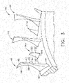
- FIGS. 3-7 illustrate a portion of an exemplary rotor stage 80 that is suitable for incorporation in the fan 12.
- the rotor stage 80 may be incorporated into one or more of the stages in the aft half of the and fan 12, particularly the last or aft-most stages.
- the rotor 46 described above defines an annular flowpath surface 82, a small section of which is shown in FIG. 3 .
- the flowpath surface 82 is depicted as a body of revolution (i.e. axisymmetric).
- the flowpath surface 82 may have a non-axisymmetric surface profile (not shown).
- each fan blade 44 extends from a root 84 at the flowpath surface 82 to a tip 86 and includes a concave pressure side 88 joined to a convex suction side 90 at a leading edge 92 and a trailing edge 94.
- each fan blade 44 has a span (or span dimension) "S1" defined as the radial distance from the root 84 to the tip 86, and a chord (or chord dimension) "C1" defined as the length of an imaginary straight line connecting the leading edge 92 and the trailing edge 94.
- its chord C1 may be different at different locations along the span S1.
- the relevant measurement is the chord C1 at the root 84.
- the fan blades 44 are uniformly spaced apart around the periphery of the flowpath surface 82.
- a non-dimensional parameter called “solidity” is defined as c/s, where "c” is equal to the blade chord as described above.
- the fan blades 44 may have a spacing which is significantly greater than a spacing that would be expected in the prior art, resulting in a blade solidity significantly less than would be expected in the prior art.
- This reduced solidity can minimize the efficiency loss resulting from "overflowing" the fan 12 in the manner described above.
- the reduced blade solidity can also have the effect of reducing weight and simplifying manufacturing by minimizing the total number of fan airfoils used in a given rotor stage.
- the rotor stage 80 may be provided with splitters, or "splittered".
- an array of splitter blades 144 extend from the flowpath surface 82.
- One splitter blade 144 is disposed between each pair of fan blades 44. In the circumferential direction, the splitter blades 144 may be located halfway or circumferentially biased between two adjacent fan blades 44. Stated another way, the fan blades 44 and splitter blades 144 alternate around the periphery of the flowpath surface 82.
- Each splitter blade 144 extends from a root 184 at the flowpath surface 82 to a tip 186, and includes a concave pressure side 188 joined to a convex suction side 190 at a leading edge 192 and a trailing edge 194.
- each splitter blade 144 has a span (or span dimension) "S2" defined as the radial distance from the root 184 to the tip 186, and a chord (or chord dimension) "C2" defined as the length of an imaginary straight line connecting the leading edge 192 and the trailing edge 194.
- S2 span dimension
- C2 chord dimension
- its chord C2 may be different at different locations along the span S2.
- the relevant measurement is the chord C2 at the root 184.
- the splitter blades 144 function to locally increase the hub solidity of the rotor stage 80 and thereby prevent the above-mentioned flow separation from the fan blades 44.
- a similar effect could be obtained by simply increasing the number of fan blades 44, and therefore reducing the blade-to-blade spacing. This, however, has the undesirable side effect of increasing aerodynamic surface area frictional losses which would manifest as reduced aerodynamic efficiency and increased rotor weight. Therefore, the dimensions of the splitter blades 144 and their position may be selected to prevent flow separation while minimizing their surface area.
- the splitter blades 144 are positioned so that their trailing edges 194 are at approximately the same axial position as the trailing edges 184 of the fan blades 44, relative to the rotor 46. this can be seen in FIG. 4 .
- the span S2 and/or the chord C2 of the splitter blades 144 may be some fraction less than unity of the corresponding span S1 and chord C1 of the fan blades 44. These may be referred to as "part-span” and/or "part-chord” splitter blades.
- the span S2 may be equal to or less than the span S1.
- the span S2 is 50% or less of the span S1.
- the span S2 is 30% or less of the span S1.
- the chord C2 may be equal to or less than the chord C1.
- the chord C2 is 80% or less of the chord C1.
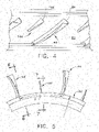
- FIGS. 8-11 illustrate a portion of an exemplary stator structure that is suitable for inclusion in the fan 12.
- the stator structure may be incorporated into one or more of the stages in the aft half of the fan 12, particularly the last or aft-most stages.
- the stator structure includes several rows of airflow-shaped fan stator vanes 50. These are bounded by an inner band 245 and the outer casing 36, respectively.
- the inner band 245 defines an annular inner flowpath surface 282, and the outer casing 36 defines an annular outer flowpath surface 272.
- the stator vanes 50 extend between the inner and outer flowpath surfaces 282, 272. Each stator vane 50 extends from a root 284 at the inner flowpath surface 282 to a tip 286 at the outer flowpath surface 272 and includes a concave pressure side 288 joined to a convex suction side 290 at a leading edge 292 and a trailing edge 294. As best seen in FIG.
- each stator vane 50 has a span (or span dimension) "S3" defined as the radial distance from the root 284 to the tip 286, and a chord (or chord dimension) "C3" defined as the length of an imaginary straight line connecting the leading edge 292 and the trailing edge 294.
- S3 span (or span dimension)
- C3 chord (or chord dimension)
- its chord C3 may be different at different locations along the span S3.
- the relevant measurement would be the chord C3 at the root 284 or tip 286.
- the stator vanes 50 are uniformly spaced apart around the periphery of the inner flowpath surface 282.
- the stator vanes 50 have a mean circumferential spacing "s”, defined as described above (see FIG. 9 ).
- a non-dimensional parameter called “solidity” is defined as c/s, where "c” is equal to the vane chord as described above.
- the stator vanes 50 may have a spacing which is significantly greater than a spacing that would be expected in the prior art, resulting in a vane solidity significantly less than would be expected in the prior art.
- the inner and outer flowpath surfaces 282, 272 are depicted as bodies of revolution (i.e. axisymmetric structures).
- either or both of the inner or outer flowpath surfaces 282, 272 may have a non-axisymmetric surface profile (not shown).
- one or both of the inner and outer flowpath surfaces 250, 272 may be provided with an array of splitter vanes.
- an array of splitter vanes 350 extend radially inward from the outer flowpath surface 272.
- One splitter vane 350 is disposed between each pair of stator vanes 50. In the circumferential direction, the splitter vanes 350 may be located halfway or circumferentially biased between two adjacent stator vanes 50. Stated another way, the stator vanes 50 and splitter vanes 350 alternate around the periphery of the outer flowpath surface 272.
- Each splitter vane 350 extends from a root 384 at the outer flowpath surface 272 to a tip 386, and includes a concave pressure side 388 joined to a convex suction side 390 at a leading edge 392 and a trailing edge 394.
- each splitter vane 350 has a span (or span dimension) "S4" defined as the radial distance from the root 384 to the tip 386, and a chord (or chord dimension) "C4" defined as the length of an imaginary straight line connecting the leading edge 392 and the trailing edge 394.
- its chord C4 may be different at different locations along the span S4.
- the relevant measurement is the chord C4 at the root 384.
- the splitter vanes 350 function to locally increase the hub solidity of the stator and thereby prevent the above-mentioned flow separation from the stator vanes 50.
- a similar effect could be obtained by simply increasing the number of stator vanes 50, and therefore reducing the vane-to-vane spacing. This, however, has the undesirable side effect of increasing aerodynamic surface area frictional losses which would manifest as reduced aerodynamic efficiency and increased stator weight. Therefore, the dimensions of the splitter vanes 350 and their position may be selected to prevent flow separation while minimizing their surface area.
- the splitter vanes 350 are positioned so that their trailing edges 394 are at approximately the same axial position as the trailing edges 294 of the stator vanes 50, relative to the outer flowpath surface 272. This can be seen in FIG. 8 .
- the span S4 and/or the chord C4 of the splitter vanes 350 may be some fraction less than unity of the corresponding span S3 and chord C3 of the stator vanes 50. These may be referred to as "part-span” and/or “part-chord” splitter vanes.
- the span S4 may be equal to or less than the span S4.
- the span S4 is 50% or less of the span S3. More preferably for the least frictional losses, the span S4 is 30% or less of the span S3.
- the chord C4 may be equal to or less than the chord C3.
- the chord C4 is 80% or less of the chord C3.
- FIG. 9 illustrates an array of splitter vanes 450 extending radially outward from the inner flowpath surface 282.
- One splitter vane 450 is disposed between each pair of stator vanes 450.
- the splitter vanes 450 may be identical to the splitter vanes 350 described above, in terms of their shape, circumferential position relative to the stator vanes 50, and their span and chord dimensions.
- splitter vanes may optionally be incorporated at the inner flowpath surface 282, or the outer flowpath surface 272, or both.
- the engine having the fan apparatus described herein with splitter airfoils has several advantages over the prior art. It increases the endwall solidity level locally, reduces the endwall aerodynamic loading level locally, and suppresses the tendency of the airfoil portion adjacent the endwall to want to separate.
- splittered fan enables variable fan pressure and bypass ratio cycles that will yield reduced engine fuel burn levels. It improves variable-cycle turbine engine performance and enables more efficient operation over wider power ranges and flight regimes.
- the concept is un-intrusive to implement.
Landscapes
- Engineering & Computer Science (AREA)
- Mechanical Engineering (AREA)
- General Engineering & Computer Science (AREA)
- Chemical & Material Sciences (AREA)
- Combustion & Propulsion (AREA)
- Physics & Mathematics (AREA)
- Fluid Mechanics (AREA)
- Geometry (AREA)
- Structures Of Non-Positive Displacement Pumps (AREA)
Claims (14)
- Mantelstromtriebwerk (10), umfassend:einen Turbomaschinenkern (30), der betriebsfähig ist, um einen Strom von Verbrennungsgasen zu erzeugen;eine Niederdruckturbine (22), die konfiguriert ist, um Energie aus dem Strom von Verbrennungsgasen zu extrahieren, um einen Fan (12) anzutreiben, um einen Fanstrom zu erzeugen, wobei der Fan (12) derart konfiguriert ist, dass zumindest ein Abschnitt des Fanstroms das Mantelstromtriebwerk (10) verlässt, ohne eine Turbine zu durchlaufen; undmindestens eine Vorrichtung mit variablem Zyklus (24, 28), die betriebsfähig ist, um einen Gegendruck stromabwärts des Fans (12) zu ändern; wobeider Fan (12) einschließt:einen Rotor (46), umfassend mindestens eine Rotorstufe, die eine drehbare Scheibe einschließt, die eine Rotorstrombahnoberfläche definiert, und eine Anordnung von Axialstromrotorprofilen (44), die sich von der Rotorstrombahnoberfläche nach außen erstrecken; undmindestens eine Statorstufe, umfassend eine Wand, die eine Statorstrombahnoberfläche definiert, und eine Anordnung von Axialstromstatorprofilen (50), die sich von der Statorstrombahnoberfläche weg erstrecken; undmindestens eine der Rotor- oder Statorstufen eine Anordnung von profilförmigen Teilerprofilen (144, 350, 450) einschließt, die sich von mindestens einer der Rotorstrombahnoberfläche oder der Statorstrombahnoberfläche erstrecken, wobei sich Teilerprofile der Anordnung von profilförmigen Teilerprofilen (144, 350, 450) mit Rotorprofilen der Anordnung von Axialstromrotorprofilen (44) oder Statorprofilen der Anordnung von Axialstromstatorprofilen (50) der entsprechenden Stufe abwechseln, wobei mindestens eine von einer Sehnenabmessung der Teilerprofile der Anordnung von profilförmigen Teilerprofilen (144, 350, 450) und einer Spannweitenabmessung der Teilerprofile der Anordnung von profilförmigen Teilerprofilen (144, 350, 450) kleiner als die entsprechende Abmessung der Rotorprofilen der Anordnung von Axialstromrotorprofilen (44) und der Statorprofilen der Anordnung von Axialstromstatorprofilen (50) der mindestens einen von den Rotor- oder Statorstufen ist.
- Mantelstromtriebwerk (10) nach Anspruch 1, wobei die Vorrichtung mit variablem Zyklus (24, 28) eine Schubdüse mit variabler Fläche ist.
- Mantelstromtriebwerk (10) nach Anspruch 1, wobei die Vorrichtung mit variablem Zyklus (24, 28) ein Bypassinjektor mit variabler Fläche ist.
- Mantelstromtriebwerk (10) nach Anspruch 1, wobei mindestens eine der Strombahnoberflächen kein Rotationskörper ist.
- Mantelstromtriebwerk (10) nach Anspruch 1, wobei jedes Teilerprofil der Anordnung von profilförmigen Teilerprofilen (144, 350, 450) etwa in der Mitte zwischen zwei angrenzenden Rotor- oder Statorprofilen (44, 50) gelegen ist.
- Mantelstromtriebwerk (10) nach Anspruch 1, wobei die Teilerprofile der Anordnung von profilförmigen Teilerprofilen (144, 350, 450) derart positioniert sind, dass Hinterkanten der Teilerprofile der Anordnung von profilförmigen Teilerprofilen (144, 350, 450) in etwa derselben axialen Position wie Hinterkanten der Rotor- oder Statorprofile (44, 50), relativ zu der entsprechenden Strombahnoberfläche, liegen.
- Mantelstromtriebwerk (10) nach Anspruch 1, wobei die Spannweitenabmessung der Teilerprofile (144, 350, 450) 50 % oder weniger der Spannweitenabmessung der entsprechenden Rotor- oder Statorprofile (44, 50) beträgt.
- Mantelstromtriebwerk (10) nach Anspruch 1, wobei die Spannweitenabmessung der Teilerprofile (144, 350, 450) 30 % oder weniger der Spannweitenabmessung der entsprechenden Rotor- oder Statorprofile (44, 50) beträgt.
- Mantelstromtriebwerk (10) nach Anspruch 5, wobei die Sehnenabmessung der Teilerprofile (144, 350, 450) an Wurzeln davon 80 % oder weniger der Sehnenabmessung der entsprechenden Rotor- oder Statorprofile (44, 50) an Wurzeln davon beträgt.
- Mantelstromtriebwerk (10) nach Anspruch 1, wobei die Sehnenabmessung der Teilerprofile (144, 350, 450) an Wurzeln davon 80 % oder weniger der Sehnenabmessung der entsprechenden Rotor- oder Statorprofile (44, 50) an Wurzeln davon beträgt.
- Mantelstromtriebwerk (10) nach Anspruch 1, wobei der Fan (12) mehrere Stator- und Rotorstufen einschließt und die Teilerprofile (144, 350, 450) in einen oder mehrere der mehreren Stator- und Rotorstufen integriert sind, die in einer hinteren Hälfte des Fans (12) gelegen sind.
- Mantelstromtriebwerk (10) nach Anspruch 1, wobei die mindestens eine von den Rotor- oder Statorstufen eine hinterste Rotor- oder Statorstufe des Fans (12) ist.
- Verfahren zum Betreiben eines Gasturbinentriebwerks mit variablem Zyklus (10), umfassend:Verwenden eines Turbomaschinenkerns (30), einschließlich in einer sequenziellen Strombeziehung: eines Kompressors, einer Brennkammer, und einer Turbine, die mit dem Kompressor mechanisch gekoppelt ist, um einen Strom von Verbrennungsgasen zu generieren;Verwenden einer Niederdruckturbine (22), um Energie aus dem Strom von Verbrennungsgasen zu extrahieren, um einen Fan (12) anzutreiben, um einen Fanstrom zu erzeugen, wobei der Fan (12) derart konfiguriert ist, dass zumindest ein Abschnitt des Fanstroms das Gasturbinentriebwerk mit variablem Zyklus (10) verlässt, ohne eine Turbine zu durchlaufen, wobei der Fan (12) mindestens eine Reihe von Teilerprofilen (144, 350, 450) integriert; undwährend des Betriebs des Gasturbinentriebwerks mit variablem Zyklus (10), Verwenden mindestens einer Vorrichtung mit variablem Zyklus (24, 28), um einen Gegendruck stromabwärts des Fans (12) zu ändern, wobei dadurch eine Betriebsleitung des Fans (12) um mindestens 5 % von einer Sollposition bewegt wird.
- Verfahren nach Anspruch 13, wobei die Vorrichtung mit variablem Zyklus (24, 28) verwendet wird, um die Fanbetriebsleitung relativ zu der Sollposition zu senken.
Applications Claiming Priority (2)
| Application Number | Priority Date | Filing Date | Title |
|---|---|---|---|
| US15/211,787 US20180017019A1 (en) | 2016-07-15 | 2016-07-15 | Turbofan engine wth a splittered rotor fan |
| PCT/US2017/040469 WO2018084902A1 (en) | 2016-07-15 | 2017-06-30 | Turbofan engine and corresponding method of operating |
Publications (2)
| Publication Number | Publication Date |
|---|---|
| EP3485146A1 EP3485146A1 (de) | 2019-05-22 |
| EP3485146B1 true EP3485146B1 (de) | 2022-12-28 |
Family
ID=60940935
Family Applications (1)
| Application Number | Title | Priority Date | Filing Date |
|---|---|---|---|
| EP17837915.2A Active EP3485146B1 (de) | 2016-07-15 | 2017-06-30 | Turbofan-triebwerk und zugehöriges betriebsverfahren |
Country Status (4)
| Country | Link |
|---|---|
| US (1) | US20180017019A1 (de) |
| EP (1) | EP3485146B1 (de) |
| CN (1) | CN109477391B (de) |
| WO (1) | WO2018084902A1 (de) |
Families Citing this family (7)
| Publication number | Priority date | Publication date | Assignee | Title |
|---|---|---|---|---|
| US11149552B2 (en) * | 2019-12-13 | 2021-10-19 | General Electric Company | Shroud for splitter and rotor airfoils of a fan for a gas turbine engine |
| US11377219B2 (en) * | 2020-04-17 | 2022-07-05 | Raytheon Technologies Corporation | Systems and methods for hybrid electric gas turbine engines |
| FR3118786B1 (fr) * | 2021-01-11 | 2023-10-20 | Safran | Ensemble de redressement |
| CN113653672B (zh) * | 2021-08-31 | 2023-11-10 | 佛山市南海九洲普惠风机有限公司 | 一种带有分流叶片的轴流叶轮 |
| US12037921B2 (en) | 2022-08-04 | 2024-07-16 | General Electric Company | Fan for a turbine engine |
| US20250223909A1 (en) * | 2022-12-21 | 2025-07-10 | General Electric Company | Outlet guide vane assembly for a turbofan engine |
| US12276199B2 (en) * | 2022-12-21 | 2025-04-15 | General Electric Company | Outlet guide vane assembly for a turbofan engine |
Family Cites Families (25)
| Publication number | Priority date | Publication date | Assignee | Title |
|---|---|---|---|---|
| GB630747A (en) * | 1947-07-09 | 1949-10-20 | George Stanley Taylor | Improvements in or relating to multi-stage axial-flow compressors |
| BE638547A (de) * | 1962-10-29 | 1900-01-01 | ||
| GB1305302A (de) * | 1970-04-28 | 1973-01-31 | ||
| GB1514096A (en) * | 1977-02-01 | 1978-06-14 | Rolls Royce | Axial flow rotor or stator assembly |
| GB2115881A (en) * | 1982-02-26 | 1983-09-14 | Rolls Royce | Gas turbine engine stator vane assembly |
| US4512718A (en) * | 1982-10-14 | 1985-04-23 | United Technologies Corporation | Tandem fan stage for gas turbine engines |
| US5152661A (en) * | 1988-05-27 | 1992-10-06 | Sheets Herman E | Method and apparatus for producing fluid pressure and controlling boundary layer |
| JP2756926B2 (ja) * | 1995-01-11 | 1998-05-25 | 川崎重工業株式会社 | ジェット推進エンジンまたはガスタービンの出力部構造 |
| EP0978632A1 (de) * | 1998-08-07 | 2000-02-09 | Asea Brown Boveri AG | Turbomaschine mit Zwischenschaufeln als Strömungsteilelemente |
| GB2405184A (en) * | 2003-08-22 | 2005-02-23 | Rolls Royce Plc | A gas turbine engine lift fan with tandem inlet guide vanes |
| US20070154314A1 (en) * | 2005-12-29 | 2007-07-05 | Minebea Co., Ltd. | Reduction of tonal noise in cooling fans using splitter blades |
| FR2907519B1 (fr) * | 2006-10-20 | 2011-12-16 | Snecma | Nageoire de plateforme de soufflante |
| US20100158684A1 (en) * | 2006-11-14 | 2010-06-24 | Baralon Stephane | Vane assembly configured for turning a flow in a gas turbine engine, a stator component comprising the vane assembly, a gas turbine and an aircraft jet engine |
| US9494084B2 (en) * | 2007-08-23 | 2016-11-15 | United Technologies Corporation | Gas turbine engine with fan variable area nozzle for low fan pressure ratio |
| US20090317237A1 (en) * | 2008-06-20 | 2009-12-24 | General Electric Company | System and method for reduction of unsteady pressures in turbomachinery |
| US8333552B2 (en) * | 2008-06-20 | 2012-12-18 | General Electric Company | Combined acoustic absorber and heat exchanging outlet guide vanes |
| DE102009011924A1 (de) * | 2009-03-10 | 2010-09-16 | Rolls-Royce Deutschland Ltd & Co Kg | Nebenstromkanal eines Turbofantriebwerks |
| DE102010014900A1 (de) * | 2010-04-14 | 2011-10-20 | Rolls-Royce Deutschland Ltd & Co Kg | Nebenstromkanal eines Turbofantriebwerkes |
| US20130051996A1 (en) * | 2011-08-29 | 2013-02-28 | Mtu Aero Engines Gmbh | Transition channel of a turbine unit |
| CA2790439A1 (en) * | 2011-09-28 | 2013-03-28 | General Electric Company | Noise reduction in a turbomachine, and a related method thereof |
| CN104011361B (zh) * | 2011-12-30 | 2017-03-29 | 联合工艺公司 | 具有用于低风扇压力比的风扇可变面积喷嘴的燃气涡轮发动机 |
| EP2799721B8 (de) * | 2013-05-03 | 2016-12-07 | Safran Aero Booster S.A. | LEITSCHAUFELANORDNUNG EINER AXIALEN TURBOMASCHINE MIT HILFSFLÜGELN AN DEN LAUFRADSCHAUFELSFÜßEN |
| FR3014943B1 (fr) * | 2013-12-18 | 2019-03-29 | Safran Aircraft Engines | Piece de turbomachine a surface non-axisymetrique |
| US9874221B2 (en) * | 2014-12-29 | 2018-01-23 | General Electric Company | Axial compressor rotor incorporating splitter blades |
| US9938984B2 (en) * | 2014-12-29 | 2018-04-10 | General Electric Company | Axial compressor rotor incorporating non-axisymmetric hub flowpath and splittered blades |
-
2016
- 2016-07-15 US US15/211,787 patent/US20180017019A1/en not_active Abandoned
-
2017
- 2017-06-30 CN CN201780043929.4A patent/CN109477391B/zh active Active
- 2017-06-30 WO PCT/US2017/040469 patent/WO2018084902A1/en not_active Ceased
- 2017-06-30 EP EP17837915.2A patent/EP3485146B1/de active Active
Also Published As
| Publication number | Publication date |
|---|---|
| CN109477391B (zh) | 2022-06-21 |
| EP3485146A1 (de) | 2019-05-22 |
| US20180017019A1 (en) | 2018-01-18 |
| WO2018084902A1 (en) | 2018-05-11 |
| CN109477391A (zh) | 2019-03-15 |
Similar Documents
| Publication | Publication Date | Title |
|---|---|---|
| US20210239132A1 (en) | Variable-cycle compressor with a splittered rotor | |
| EP3485146B1 (de) | Turbofan-triebwerk und zugehöriges betriebsverfahren | |
| JP4953924B2 (ja) | 内側及び外側翼形部間のシュラウドの位置において異なる内側及び外側翼形部食違い角を有するfladeファン | |
| US6195983B1 (en) | Leaned and swept fan outlet guide vanes | |
| US7631484B2 (en) | High pressure ratio aft fan | |
| EP3187712B1 (de) | Kurzer gondeleinlass | |
| US9874221B2 (en) | Axial compressor rotor incorporating splitter blades | |
| EP3608505B1 (de) | Turbine mit seitenwandführung | |
| CN107829958A (zh) | 带有低部分翼展实度的飞行器风扇 | |
| EP3163028A1 (de) | Verdichtervorrichtung | |
| US11933193B2 (en) | Turbine engine with an airfoil having a set of dimples | |
| US11149552B2 (en) | Shroud for splitter and rotor airfoils of a fan for a gas turbine engine | |
| US10465523B2 (en) | Gas turbine component with platform cooling | |
| US20200123918A1 (en) | Compressor stator with leading edge fillet | |
| US12037921B2 (en) | Fan for a turbine engine | |
| CN108799202A (zh) | 具有包括导流板的排放槽的压缩机设备 | |
| US20180156124A1 (en) | Turbine engine frame incorporating splitters | |
| US9938840B2 (en) | Stator vane with platform having sloped face | |
| US10519976B2 (en) | Fluid diodes with ridges to control boundary layer in axial compressor stator vane | |
| CN120100535A (zh) | 具有固定和可变桨距入口导向轮叶的导向轮叶组件 | |
| EP3108117B2 (de) | Gasturbinenmotorschaufel | |
| EP3470627B1 (de) | Gasturbinenmotorschaufel | |
| EP3108112B1 (de) | Turboluftstrahltriebwerk mit getriebefan und niederdruckverdichterschaufeln |
Legal Events
| Date | Code | Title | Description |
|---|---|---|---|
| STAA | Information on the status of an ep patent application or granted ep patent |
Free format text: STATUS: UNKNOWN |
|
| STAA | Information on the status of an ep patent application or granted ep patent |
Free format text: STATUS: THE INTERNATIONAL PUBLICATION HAS BEEN MADE |
|
| PUAI | Public reference made under article 153(3) epc to a published international application that has entered the european phase |
Free format text: ORIGINAL CODE: 0009012 |
|
| STAA | Information on the status of an ep patent application or granted ep patent |
Free format text: STATUS: REQUEST FOR EXAMINATION WAS MADE |
|
| 17P | Request for examination filed |
Effective date: 20190215 |
|
| AK | Designated contracting states |
Kind code of ref document: A1 Designated state(s): AL AT BE BG CH CY CZ DE DK EE ES FI FR GB GR HR HU IE IS IT LI LT LU LV MC MK MT NL NO PL PT RO RS SE SI SK SM TR |
|
| AX | Request for extension of the european patent |
Extension state: BA ME |
|
| DAV | Request for validation of the european patent (deleted) | ||
| DAX | Request for extension of the european patent (deleted) | ||
| STAA | Information on the status of an ep patent application or granted ep patent |
Free format text: STATUS: EXAMINATION IS IN PROGRESS |
|
| 17Q | First examination report despatched |
Effective date: 20210503 |
|
| GRAP | Despatch of communication of intention to grant a patent |
Free format text: ORIGINAL CODE: EPIDOSNIGR1 |
|
| STAA | Information on the status of an ep patent application or granted ep patent |
Free format text: STATUS: GRANT OF PATENT IS INTENDED |
|
| INTG | Intention to grant announced |
Effective date: 20220810 |
|
| GRAS | Grant fee paid |
Free format text: ORIGINAL CODE: EPIDOSNIGR3 |
|
| GRAA | (expected) grant |
Free format text: ORIGINAL CODE: 0009210 |
|
| STAA | Information on the status of an ep patent application or granted ep patent |
Free format text: STATUS: THE PATENT HAS BEEN GRANTED |
|
| AK | Designated contracting states |
Kind code of ref document: B1 Designated state(s): AL AT BE BG CH CY CZ DE DK EE ES FI FR GB GR HR HU IE IS IT LI LT LU LV MC MK MT NL NO PL PT RO RS SE SI SK SM TR |
|
| REG | Reference to a national code |
Ref country code: GB Ref legal event code: FG4D |
|
| REG | Reference to a national code |
Ref country code: CH Ref legal event code: EP |
|
| REG | Reference to a national code |
Ref country code: DE Ref legal event code: R096 Ref document number: 602017065081 Country of ref document: DE |
|
| REG | Reference to a national code |
Ref country code: AT Ref legal event code: REF Ref document number: 1540611 Country of ref document: AT Kind code of ref document: T Effective date: 20230115 |
|
| REG | Reference to a national code |
Ref country code: IE Ref legal event code: FG4D |
|
| REG | Reference to a national code |
Ref country code: LT Ref legal event code: MG9D |
|
| PG25 | Lapsed in a contracting state [announced via postgrant information from national office to epo] |
Ref country code: SE Free format text: LAPSE BECAUSE OF FAILURE TO SUBMIT A TRANSLATION OF THE DESCRIPTION OR TO PAY THE FEE WITHIN THE PRESCRIBED TIME-LIMIT Effective date: 20221228 Ref country code: NO Free format text: LAPSE BECAUSE OF FAILURE TO SUBMIT A TRANSLATION OF THE DESCRIPTION OR TO PAY THE FEE WITHIN THE PRESCRIBED TIME-LIMIT Effective date: 20230328 Ref country code: LT Free format text: LAPSE BECAUSE OF FAILURE TO SUBMIT A TRANSLATION OF THE DESCRIPTION OR TO PAY THE FEE WITHIN THE PRESCRIBED TIME-LIMIT Effective date: 20221228 Ref country code: FI Free format text: LAPSE BECAUSE OF FAILURE TO SUBMIT A TRANSLATION OF THE DESCRIPTION OR TO PAY THE FEE WITHIN THE PRESCRIBED TIME-LIMIT Effective date: 20221228 |
|
| REG | Reference to a national code |
Ref country code: NL Ref legal event code: MP Effective date: 20221228 |
|
| REG | Reference to a national code |
Ref country code: AT Ref legal event code: MK05 Ref document number: 1540611 Country of ref document: AT Kind code of ref document: T Effective date: 20221228 |
|
| PG25 | Lapsed in a contracting state [announced via postgrant information from national office to epo] |
Ref country code: RS Free format text: LAPSE BECAUSE OF FAILURE TO SUBMIT A TRANSLATION OF THE DESCRIPTION OR TO PAY THE FEE WITHIN THE PRESCRIBED TIME-LIMIT Effective date: 20221228 Ref country code: LV Free format text: LAPSE BECAUSE OF FAILURE TO SUBMIT A TRANSLATION OF THE DESCRIPTION OR TO PAY THE FEE WITHIN THE PRESCRIBED TIME-LIMIT Effective date: 20221228 Ref country code: HR Free format text: LAPSE BECAUSE OF FAILURE TO SUBMIT A TRANSLATION OF THE DESCRIPTION OR TO PAY THE FEE WITHIN THE PRESCRIBED TIME-LIMIT Effective date: 20221228 Ref country code: GR Free format text: LAPSE BECAUSE OF FAILURE TO SUBMIT A TRANSLATION OF THE DESCRIPTION OR TO PAY THE FEE WITHIN THE PRESCRIBED TIME-LIMIT Effective date: 20230329 |
|
| P01 | Opt-out of the competence of the unified patent court (upc) registered |
Effective date: 20230411 |
|
| PG25 | Lapsed in a contracting state [announced via postgrant information from national office to epo] |
Ref country code: NL Free format text: LAPSE BECAUSE OF FAILURE TO SUBMIT A TRANSLATION OF THE DESCRIPTION OR TO PAY THE FEE WITHIN THE PRESCRIBED TIME-LIMIT Effective date: 20221228 |
|
| PG25 | Lapsed in a contracting state [announced via postgrant information from national office to epo] |
Ref country code: SM Free format text: LAPSE BECAUSE OF FAILURE TO SUBMIT A TRANSLATION OF THE DESCRIPTION OR TO PAY THE FEE WITHIN THE PRESCRIBED TIME-LIMIT Effective date: 20221228 Ref country code: RO Free format text: LAPSE BECAUSE OF FAILURE TO SUBMIT A TRANSLATION OF THE DESCRIPTION OR TO PAY THE FEE WITHIN THE PRESCRIBED TIME-LIMIT Effective date: 20221228 Ref country code: PT Free format text: LAPSE BECAUSE OF FAILURE TO SUBMIT A TRANSLATION OF THE DESCRIPTION OR TO PAY THE FEE WITHIN THE PRESCRIBED TIME-LIMIT Effective date: 20230428 Ref country code: ES Free format text: LAPSE BECAUSE OF FAILURE TO SUBMIT A TRANSLATION OF THE DESCRIPTION OR TO PAY THE FEE WITHIN THE PRESCRIBED TIME-LIMIT Effective date: 20221228 Ref country code: EE Free format text: LAPSE BECAUSE OF FAILURE TO SUBMIT A TRANSLATION OF THE DESCRIPTION OR TO PAY THE FEE WITHIN THE PRESCRIBED TIME-LIMIT Effective date: 20221228 Ref country code: CZ Free format text: LAPSE BECAUSE OF FAILURE TO SUBMIT A TRANSLATION OF THE DESCRIPTION OR TO PAY THE FEE WITHIN THE PRESCRIBED TIME-LIMIT Effective date: 20221228 Ref country code: AT Free format text: LAPSE BECAUSE OF FAILURE TO SUBMIT A TRANSLATION OF THE DESCRIPTION OR TO PAY THE FEE WITHIN THE PRESCRIBED TIME-LIMIT Effective date: 20221228 |
|
| PG25 | Lapsed in a contracting state [announced via postgrant information from national office to epo] |
Ref country code: SK Free format text: LAPSE BECAUSE OF FAILURE TO SUBMIT A TRANSLATION OF THE DESCRIPTION OR TO PAY THE FEE WITHIN THE PRESCRIBED TIME-LIMIT Effective date: 20221228 Ref country code: PL Free format text: LAPSE BECAUSE OF FAILURE TO SUBMIT A TRANSLATION OF THE DESCRIPTION OR TO PAY THE FEE WITHIN THE PRESCRIBED TIME-LIMIT Effective date: 20221228 Ref country code: IS Free format text: LAPSE BECAUSE OF FAILURE TO SUBMIT A TRANSLATION OF THE DESCRIPTION OR TO PAY THE FEE WITHIN THE PRESCRIBED TIME-LIMIT Effective date: 20230428 Ref country code: AL Free format text: LAPSE BECAUSE OF FAILURE TO SUBMIT A TRANSLATION OF THE DESCRIPTION OR TO PAY THE FEE WITHIN THE PRESCRIBED TIME-LIMIT Effective date: 20221228 |
|
| REG | Reference to a national code |
Ref country code: DE Ref legal event code: R097 Ref document number: 602017065081 Country of ref document: DE |
|
| PG25 | Lapsed in a contracting state [announced via postgrant information from national office to epo] |
Ref country code: DK Free format text: LAPSE BECAUSE OF FAILURE TO SUBMIT A TRANSLATION OF THE DESCRIPTION OR TO PAY THE FEE WITHIN THE PRESCRIBED TIME-LIMIT Effective date: 20221228 |
|
| PLBE | No opposition filed within time limit |
Free format text: ORIGINAL CODE: 0009261 |
|
| STAA | Information on the status of an ep patent application or granted ep patent |
Free format text: STATUS: NO OPPOSITION FILED WITHIN TIME LIMIT |
|
| 26N | No opposition filed |
Effective date: 20230929 |
|
| PG25 | Lapsed in a contracting state [announced via postgrant information from national office to epo] |
Ref country code: MC Free format text: LAPSE BECAUSE OF FAILURE TO SUBMIT A TRANSLATION OF THE DESCRIPTION OR TO PAY THE FEE WITHIN THE PRESCRIBED TIME-LIMIT Effective date: 20221228 |
|
| PG25 | Lapsed in a contracting state [announced via postgrant information from national office to epo] |
Ref country code: SI Free format text: LAPSE BECAUSE OF FAILURE TO SUBMIT A TRANSLATION OF THE DESCRIPTION OR TO PAY THE FEE WITHIN THE PRESCRIBED TIME-LIMIT Effective date: 20221228 Ref country code: MC Free format text: LAPSE BECAUSE OF FAILURE TO SUBMIT A TRANSLATION OF THE DESCRIPTION OR TO PAY THE FEE WITHIN THE PRESCRIBED TIME-LIMIT Effective date: 20221228 |
|
| REG | Reference to a national code |
Ref country code: CH Ref legal event code: PL |
|
| REG | Reference to a national code |
Ref country code: BE Ref legal event code: MM Effective date: 20230630 |
|
| PG25 | Lapsed in a contracting state [announced via postgrant information from national office to epo] |
Ref country code: LU Free format text: LAPSE BECAUSE OF NON-PAYMENT OF DUE FEES Effective date: 20230630 |
|
| REG | Reference to a national code |
Ref country code: IE Ref legal event code: MM4A |
|
| PG25 | Lapsed in a contracting state [announced via postgrant information from national office to epo] |
Ref country code: LU Free format text: LAPSE BECAUSE OF NON-PAYMENT OF DUE FEES Effective date: 20230630 |
|
| PG25 | Lapsed in a contracting state [announced via postgrant information from national office to epo] |
Ref country code: IE Free format text: LAPSE BECAUSE OF NON-PAYMENT OF DUE FEES Effective date: 20230630 |
|
| PG25 | Lapsed in a contracting state [announced via postgrant information from national office to epo] |
Ref country code: IE Free format text: LAPSE BECAUSE OF NON-PAYMENT OF DUE FEES Effective date: 20230630 Ref country code: CH Free format text: LAPSE BECAUSE OF NON-PAYMENT OF DUE FEES Effective date: 20230630 |
|
| PG25 | Lapsed in a contracting state [announced via postgrant information from national office to epo] |
Ref country code: IT Free format text: LAPSE BECAUSE OF FAILURE TO SUBMIT A TRANSLATION OF THE DESCRIPTION OR TO PAY THE FEE WITHIN THE PRESCRIBED TIME-LIMIT Effective date: 20221228 Ref country code: BE Free format text: LAPSE BECAUSE OF NON-PAYMENT OF DUE FEES Effective date: 20230630 |
|
| PG25 | Lapsed in a contracting state [announced via postgrant information from national office to epo] |
Ref country code: BG Free format text: LAPSE BECAUSE OF FAILURE TO SUBMIT A TRANSLATION OF THE DESCRIPTION OR TO PAY THE FEE WITHIN THE PRESCRIBED TIME-LIMIT Effective date: 20221228 |
|
| PG25 | Lapsed in a contracting state [announced via postgrant information from national office to epo] |
Ref country code: BG Free format text: LAPSE BECAUSE OF FAILURE TO SUBMIT A TRANSLATION OF THE DESCRIPTION OR TO PAY THE FEE WITHIN THE PRESCRIBED TIME-LIMIT Effective date: 20221228 |
|
| PGFP | Annual fee paid to national office [announced via postgrant information from national office to epo] |
Ref country code: DE Payment date: 20250520 Year of fee payment: 9 |
|
| PGFP | Annual fee paid to national office [announced via postgrant information from national office to epo] |
Ref country code: GB Payment date: 20250520 Year of fee payment: 9 |
|
| PGFP | Annual fee paid to national office [announced via postgrant information from national office to epo] |
Ref country code: FR Payment date: 20250520 Year of fee payment: 9 |
|
| PG25 | Lapsed in a contracting state [announced via postgrant information from national office to epo] |
Ref country code: CY Free format text: LAPSE BECAUSE OF FAILURE TO SUBMIT A TRANSLATION OF THE DESCRIPTION OR TO PAY THE FEE WITHIN THE PRESCRIBED TIME-LIMIT; INVALID AB INITIO Effective date: 20170630 |
|
| PG25 | Lapsed in a contracting state [announced via postgrant information from national office to epo] |
Ref country code: HU Free format text: LAPSE BECAUSE OF FAILURE TO SUBMIT A TRANSLATION OF THE DESCRIPTION OR TO PAY THE FEE WITHIN THE PRESCRIBED TIME-LIMIT; INVALID AB INITIO Effective date: 20170630 |
|
| PG25 | Lapsed in a contracting state [announced via postgrant information from national office to epo] |
Ref country code: TR Free format text: LAPSE BECAUSE OF FAILURE TO SUBMIT A TRANSLATION OF THE DESCRIPTION OR TO PAY THE FEE WITHIN THE PRESCRIBED TIME-LIMIT Effective date: 20221228 |