EP3485154B1 - Viertakt-v-verbrennungsmotor mit 16 zylindern - Google Patents
Viertakt-v-verbrennungsmotor mit 16 zylindern Download PDFInfo
- Publication number
- EP3485154B1 EP3485154B1 EP17745650.6A EP17745650A EP3485154B1 EP 3485154 B1 EP3485154 B1 EP 3485154B1 EP 17745650 A EP17745650 A EP 17745650A EP 3485154 B1 EP3485154 B1 EP 3485154B1
- Authority
- EP
- European Patent Office
- Prior art keywords
- engine
- firing
- internal combustion
- type
- crank
- Prior art date
- Legal status (The legal status is an assumption and is not a legal conclusion. Google has not performed a legal analysis and makes no representation as to the accuracy of the status listed.)
- Active
Links
Images


Classifications
-
- F—MECHANICAL ENGINEERING; LIGHTING; HEATING; WEAPONS; BLASTING
- F02—COMBUSTION ENGINES; HOT-GAS OR COMBUSTION-PRODUCT ENGINE PLANTS
- F02B—INTERNAL-COMBUSTION PISTON ENGINES; COMBUSTION ENGINES IN GENERAL
- F02B75/00—Other engines
- F02B75/16—Engines characterised by number of cylinders, e.g. single-cylinder engines
- F02B75/18—Multi-cylinder engines
- F02B75/22—Multi-cylinder engines with cylinders in V, fan, or star arrangement
-
- F—MECHANICAL ENGINEERING; LIGHTING; HEATING; WEAPONS; BLASTING
- F16—ENGINEERING ELEMENTS AND UNITS; GENERAL MEASURES FOR PRODUCING AND MAINTAINING EFFECTIVE FUNCTIONING OF MACHINES OR INSTALLATIONS; THERMAL INSULATION IN GENERAL
- F16C—SHAFTS; FLEXIBLE SHAFTS; ELEMENTS OR CRANKSHAFT MECHANISMS; ROTARY BODIES OTHER THAN GEARING ELEMENTS; BEARINGS
- F16C3/00—Shafts; Axles; Cranks; Eccentrics
- F16C3/04—Crankshafts, eccentric-shafts; Cranks, eccentrics
- F16C3/06—Crankshafts
-
- F—MECHANICAL ENGINEERING; LIGHTING; HEATING; WEAPONS; BLASTING
- F16—ENGINEERING ELEMENTS AND UNITS; GENERAL MEASURES FOR PRODUCING AND MAINTAINING EFFECTIVE FUNCTIONING OF MACHINES OR INSTALLATIONS; THERMAL INSULATION IN GENERAL
- F16F—SPRINGS; SHOCK-ABSORBERS; MEANS FOR DAMPING VIBRATION
- F16F15/00—Suppression of vibrations in systems; Means or arrangements for avoiding or reducing out-of-balance forces, e.g. due to motion
- F16F15/22—Compensation of inertia forces
- F16F15/24—Compensation of inertia forces of crankshaft systems by particular disposition of cranks, pistons, or the like
-
- F—MECHANICAL ENGINEERING; LIGHTING; HEATING; WEAPONS; BLASTING
- F02—COMBUSTION ENGINES; HOT-GAS OR COMBUSTION-PRODUCT ENGINE PLANTS
- F02B—INTERNAL-COMBUSTION PISTON ENGINES; COMBUSTION ENGINES IN GENERAL
- F02B75/00—Other engines
- F02B75/16—Engines characterised by number of cylinders, e.g. single-cylinder engines
- F02B75/18—Multi-cylinder engines
- F02B2075/1804—Number of cylinders
- F02B2075/1864—Number of cylinders sixteen
Definitions
- the present invention relates to a V-type 4-stroke internal combustion engine with 16 cylinders, having a counter-clockwise or a clockwise direction of rotation.
- the object of the present invention is to provide improved firing sequences and/or crank stars for a V-type 4-stroke internal combustion engine with 16 cylinders.
- the present invention provides a V-type 4-stroke internal combustion engine having 16 cylinders, having a counter-clockwise or clockwise direction of rotation, comprising a crankshaft, a torsional vibration damper and a flywheel arranged on the crankshaft, wherein the crankshaft has 8 crank throws forming a crank star, wherein in each case the piston rods of the two cylinders of a V-segment are connected to the same crank throw, wherein the crank star is of the lengthwise symmetric or lengthwise quasi-symmetric type, wherein the crank throws C1 to C8 have one of the following angular sequences in the direction of rotation of the engine when seen from the side of the flywheel, with the crank throws numbered as C1 to C8 when starting from the side of the flywheel:
- crank stars have advantageous dynamic behaviors, especially with respect to axial vibrations. Further, advantageous firing sequences can be found for these crank stars.
- a specific angular sequence of the crank throws in the direction of rotation of the engine means that if one moves around the static crankstar in the direction of rotation, one encounters the crank throws in this sequence. This also means that if one turns the crank star in the direction of rotation, the crank throws will pass a fixed angle in the opposite sequence.
- the same principle of course also applies if the direction of rotation is specified as clockwise or anti-clockwise.
- crank throws are included in the sequence as a couple, such as C1,C8, this means that they have the same or approximately the same angular position, depending on whether the crank-star is of the symmetric and the quasi-symmetric type.
- the order of notation of the two crank throws within the couple does not imply a required angular sequence between these two crank throws for quasi-symmetric type.
- the V-type 4-stroke internal combustion engine with 16 cylinders has a counter-clockwise direction of rotation and comprises a firing sequence controller that fires the cylinders A1 to A8 and B1 to B8 in at least one of the following firing sequences, wherein the direction of rotation and the cylinder numbering is defined in accordance with DIN ISO 1204:
- the V-type 4-stroke internal combustion engine with 16-cylinders has a clockwise direction of rotation and comprises a firing sequence controller that fires the cylinders A1 to A8 and B1 to B8 in at least one of the following firing sequences, wherein the direction of rotation and the cylinder numbering is defined in accordance with DIN ISO 1204:
- the firing sequences were obtained by multi-criteria hierarchical analysis.
- crank star is one of the following:
- V-angle of the V-type 4-stroke internal combustion engine of the present invention is between 40° and 80°, more preferably between 50° and 70°, more preferably between 55° and 65°, most preferably at 60°.
- the crank star of the engine is of the lengthwise symmetric or quasi-symmetric type.
- Lengthwise symmetric means that two crank throws having the same distance from the middle plane of the crankshaft have the same angular position.
- Lengthwise quasi-symmetric means that certain deviations from an exactly symmetric position are possible.
- the angular difference between two crank throws having the same distance from the middle plane of the crankshaft is below 5°, preferably below 3°, more preferably below 1°.
- the angular distance between two crank throws following each other is between 80° and 100° or between 170° and 190°, preferably between 85° and 95° or between 175° and 185°, more preferably between 89° and 91° or between 179° and 181° and most preferably at 90° or 180°.
- the firing sequences have, for the counter-clockwise direction of rotation, an angular firing distance for a firing of a cylinder of the B-bank followed by a firing of a cylinder of the A-bank of between 45° and 75°, preferably between 55° and 65°, most preferably at 60° and/or the firing sequences have, for the counter-clockwise direction of rotation, an angular firing distance for a firing of a cylinder of the A-bank followed by a firing of a cylinder of the B-bank of between 15° and 45°, preferably between 25° and 35°, most preferably at 30°.
- the firing sequences have, for the clockwise direction of rotation, an angular firing distance for a firing of a cylinder of the A-bank followed by a firing of a cylinder of the B-bank of between 45° and 75°, preferably between 55° and 65°, most preferably at 60° and/or the firing sequences have, for the clockwise direction of rotation, an angular firing distance for a firing of a cylinder of the B-bank followed by a firing of a cylinder of the A-bank of between 15° and 45°, preferably between 25° and 35°, most preferably at 30°.
- the crank shaft is made from a self-ageing, micro-alloyed steel. This is made possible by the lower vibrations provided by the present invention.
- the engine comprises a torsional vibration damper.
- the power dissipation of the torsional vibration damper is below 6 per mil of the maximum engine power, more preferably below 5 per mil, more preferably below 3,5 per mil, more preferably below 2,5 per mil, most preferably below 2 per mil.
- the torsional vibration damper is a viscous damper.
- the torsional vibration damper is arranged on the opposite side of the crankshaft from the flywheel.
- the displacement volume per cylinder is between 2 l and 15 l, preferably between 4 I and 12 I, more preferably between 5 I and 9 I.
- the maximum engine power per liter displacement volume is between 10 kW and 80 kW, preferably between 20 kW and 50 kW.
- the engine has an operating speed range of between 600 and 2100 rpm.
- the engine has an engine controller programmed to run the engine at a constant nominal operating speed, wherein the constant nominal operating speed preferably can be adapted based on engine conditions and/or load conditions, and/or the constant nominal operating speed preferably is from an operating speed range between 600 and 2100 rpm.
- the engine is operable with a gaseous and/or with a liquid fuels, wherein the engine can preferably be operated with at least one of the following fuels: gas, diesel, gasoline.
- the engine has a direct injection system and/or a high pressure injection system.
- the engine can be operated with a Diesel or an Otto combustion method.
- the engine controller is programmed to operate the engine with a homogeneous charge and/or stratified charge combustion method.
- the engine is a suction engine or has a charging system having one or several stages.
- all cylinders of one cylinder bank have a common intake manifold and/or a common exhaust manifold, wherein the exhaust manifolds are preferably arranged with respect to the V-angle on the inside and the intake manifolds are arranged with respect to the V-angle on the outside.
- the engine is used as a power unit in a heavy duty and/or mining and/or earth moving and/or transport and/or cargo and/or load handling machine, preferably for an excavator and/or an dumper truck.
- the engine is used to run a generator and/or a hydraulic pump, the generator and/or the hydraulic pump preferably operating one or more drives of an undercarriage and/or working equipment, preferably of a heavy duty and/or mining and/or earth moving and/or transport and/or cargo and/or load handling machine, preferably for an excavator and/or an dumper truck.
- the engine is coupled directly or via a mechanical gear train to an undercarriage and/or working equipment, preferably of a heavy duty and/or mining and/or earth moving and/or transport and/or cargo and/or load handling machine, preferably for an excavator and/or an dumper truck.
- an undercarriage and/or working equipment preferably of a heavy duty and/or mining and/or earth moving and/or transport and/or cargo and/or load handling machine, preferably for an excavator and/or an dumper truck.
- the engine is used as the main power unit for a ship and/or a train.
- the engine is used as a power unit in military equipment and/or for fluid transport and/or for gas and/or fuel production and/or treatment. In an embodiment of the invention, the engine is used as a power unit for power generation, an in particular drives a generator.
- the engine is used as a power unit for a mobile and/or stationary machine.
- the engine is coupled torsionally stiffly and/or via a torsionally elastic coupling to the load.
- the present invention further comprises a machine comprising a V-type 4-stroke internal combustion engine according to any one of the above described aspects and/or embodiments.
- the machine and/or the engine has one, more or all the features described above.
- the machine can be a stationary or mobile machine, in particular a heavy duty and/or mining and/or earth moving and/or transport and/or cargo and/or load handling machine, and/or ship and/or train and/or military and/or fluid transport and/or gas and/or oil production and/or treatment machine and/or power generator.
- the machine is an excavator and/or an dumper truck.
- the present invention further comprises a crank shaft for a V-type 4-stroke internal combustion engine as described above.
- the machine and/or the engine has one, more or all the features described above.
- crank star is for a V-type 4-stroke internal combustion engine having 16 cylinders, and is formed by 8 crank throws arranged on a crankshaft, wherein in each case the piston rods of the two cylinders of a V-segment can be connected to the same crank throw, wherein the crank star is of the lengthwise symmetric or lengthwise quasi-symmetric type, wherein the crank throws C1 to C8 have one of the following angular sequences in one direction of rotation when seen from one side of the crankshaft, with the crank throws numbered as C1 to C8 when starting from the side of the flywheel:
- a torsional vibration damper and/or a flywheel can be arranged on the crankshaft.
- the angular sequences provided above is realized in the direction of rotation of the engine and/or when seen from the side of the flywheel.
- the present invention further comprises firing sequence controller or a software for a V-type 4-stroke internal combustion engine with 16 cylinders, in particular for a V-type 4-stroke internal combustion engine according to any of the preceding claims, the firing sequence controller or software implementing at least one of the firing sequences provided above.
- the present invention further comprises method for operating a V-type 4-stroke internal combustion engine with 16 cylinders, wherein the engine is operated with at least one out of the firing sequences provided above.
- the method and/or the engine has one, more or all the features described above.
- the method is a method of operation of a V-type 4-stroke internal combustion engine according to any one of the above described aspects and/or embodiments.
- the present invention relates to a 4-Stroke V-type 16-cylinder internal combustion engine equipped with lengthwise symmetric crankshaft.
- the current invention could be used in several applications like Mining, stationary power sources, Marine, etc. and for multiple engine variants like super-charged and turbocharged configurations.
- the engine could e. g. have a brake power in the range of 2000 kW up to 3500 kW.
- the displacement of the engine could e. g. be between 60 I to 100 I.
- the engine has an operating speed range from 600rpm up to 2100 rpm, rotating in counter clockwise or in clockwise direction.
- the crankshaft of the engine is formed by a succession of 8 crank throws forming a crank star. There are 8 crank throws because the piston rods of the two cylinders of a V-segment are connected to the same crank throw. Further, a torsional vibration damper and a flywheel are attached on the crankshaft.
- crankshaft is subject to significant force loads caused by cylinder pressure and accelerations of piston and connecting rod, as well as the corresponding reaction forces in the main bearings.
- these forces can induce significant vibrational phenomena for the corresponding deformation shapes, which represent additional dynamic loads.
- these dynamic loads correspond to a coincidence between combustion and/or inertial excitation frequencies and one or more crankshaft eigenfrequencies, with related torsional, bending or axial mode shape.
- High-speed Diesel engines are characterized by a wide operating speed range associated to multiple excitation harmonics, which makes it virtually impossible to avoid resonances.
- crankshaft bending vibrations are generally well controlled by the main bearings being placed between each single crank. Nevertheless, significant bending effects can occur on both crankshaft ends. On the rear end, this is the case for heavy flywheels, couplings or single bearing generators in the framework of Electric-Diesel Powertrains. At the front end, very heavy torsional vibration dampers can also contribute significantly to bending vibrations. Whirling motion of the flywheel and/or the torsional vibration damper could be observed, which increases outer fillets' stresses. A typical solution for this problem is to increase bending stiffness of the outermost webs of the crankshaft, or to add support bearings to the affected crankshaft end.
- axial vibrations represent a direct result of the crankshaft design and the attached masses, namely flywheel, coupling, torsional damper, and conrods.
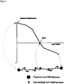
- the occurrence of axial resonances in the engine speed range leads to a succession of "lengthening” and “shortening" of the crankshaft, which is obviously characterized by a given amplitude and frequency, see Fig. 2 .
- Operating under axial resonance results in excessive increase of fillet stresses as well as very high loads on the axial thrust bearing.
- high axial accelerations at the crankshaft's front end typically occur.
- efficient solutions for controlling crankshaft axial vibration are not clearly identified in literature today.
- Axial vibration dampers are, consequently, rarely used in modern high-speed Diesel engines, and are always considered as encumbering devices from design space standpoint resulting in an extra cost for the project. Without understanding and controlling crankshaft axial behavior, its effect is considered by means of additional "unknown" stresses or increasing safety factor margins when analyzing fatigue results.
- excitation signal is given by the projection of all excitation forces on the mode shape.
- the main contribution comes from radial crankpin forces.
- the corresponding modal excitation signal is given by the sum of all radial crankpin forces.
- the main influence on the signal is the V-angle of the engine, as it determines the phase shift between the single cylinder forces.
- the V60° cranktrain has a lengthwise symmetric crankshaft, and firing distance is given by 30° - 60° sequences. Due to the non-equidistant firing intervals, the base order 4.0 has significant order amplitude. It has to be noticed that the zero order corresponds to static components of the excitation.
- any resonance, i.e. coincidence between axial eigenfrequency and excitation frequency has to be avoided by an acceptable margin, called separation margin.
- separation margin an acceptable margin
- Campbell diagram provides an excellent overview, and helps to identify critical speeds, see Fig. 3 . From this picture, it is clear that first axial frequency of the crankshaft under consideration is excited by the major 4.0 th order excitation of the V60° cranktrain near to nominal engine speed, which has to be improved.
- a resonance phenomenon occurs when the excitation coincides with an eigenmode in terms of shape and frequency.
- a vibration mode is characterized by a frequency and its related mode shape. Every mode shape contains vibration node(s) and anti-node(s), see Fig. 4 .
- a node is a point that undergoes zero displacement, and is located at all points where the mode shape plot crosses the x-axis.
- An anti-node corresponds to the maximum normalized displacement. In the context of modal analysis, it is meaningless to refer to absolute displacements, as these result from the corresponding excitation, which is not considered at modal analysis.
- the only information that can be obtained from a mode shape is the relationship between the displacements at the various locations.
- crankshaft axial eigenfrequency could be achieved by stiffening the crankshaft near to the vibration node in the middle of the crankshaft, or by reducing the mass at anti-node locations, i.e. at both ends.
- the first crankshaft axial mode shape is characterized by a lengthening and shortening of the crankshaft like an "accordion". Therefore, the node is located near to the middle of the crankshaft. Both ends of the crankshaft constitute an anti-node location for the first axial mode shape.
- the first measure to increase crankshaft's axial eigenfrequency consists of mass reduction of the components attached to crankshaft ends, namely the flywheel and the torsional vibration damper.
- the flywheel this is difficult to achieve, as a certain value of inertia has to be maintained in order to limit speed drop at dynamic load steps.
- on the front end using lighter TVD is possible by means of different technology like leaf spring damper instead of viscous-type one. Nevertheless, this modification affects heavily crankshaft free end design (oil supply from engine), modifies torsional tuning, and finally ends up with significant increase of component cost. Accordingly, further alternatives have to be found calling for less severe impacts.
- Axial stiffness of a web depends not only on its thickness and width, but also on the angular positions of the neighboring cranks.
- crank star the arrangement of the cranks along the crankshaft, the so-called crank star.
- a V16-cylinder is built of a succession of 8 crank throws with an intermediate angle of 90° or 180°. Based on FEM analysis, it turned out that two consecutive crank throws with an intermediate angle of 90° have approximately 60% higher axial stiffness than two consecutive crank throws with an intermediate angle of 180°.
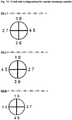
- crankshaft has four crank throws with an intermediate angles of 180°, where two are located close to the critical location in the center, between crank 3 / 4 and 5/6, see Fig. 5 (left). From geometric point of view, it is also possible to build a crank star which has only 90° intermediate angles, and none with 180°, see Fig. 5 (right), and another crank star with only two intermediate angles of 180°, see Fig. 5 (middle). By considering the mirrors of these afore mentioned three crank stars, the total conceivable six crank stars in the framework of V16-cylinder symmetric crankshaft are obtained.
- crank stars chosen, after finalizing the complete multi-modal analysis, for an engine with counter-clockwise rotation (when seen from the side of the flywheel) are shown in Fig. 12
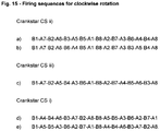
- the three crank stars chosen for an engine with clockwise rotation are shown in Fig. 13 .
- the crank star discussed above is CS iii) from Fig. 12 .
- a key parameter for the design of multi-cylinder reciprocating internal combustion engines is the choice of an appropriate firing sequence.
- engines with a small number of cylinders like inline engines with up to 6 cylinders, and V-engines with up to 12 cylinders, the number of feasible sequences is rather low and well-described in literature.
- the number of possible sequences grows disproportionate to the number of cylinders, while the vibrational systems of crankshaft and engine block become more complex at the same time.
- the selection of appropriate firing sequences for such engines requires an in-depth understanding of the above mentioned aspects, and a systematic assessment based on optimization techniques is required.
- the claimed invention is a set of firing sequences for V16-cylinder engines with favorable properties regarding crankshaft torsional vibrations, gas cycle dynamics, main bearing loads, and engine operational vibrations. They are the result of an extensive study of a V16-cylinder engine, and can be applied to a class of V-type 16-cylinder engines for various applications.
- crankshaft dynamics influences are considered herein.
- the central role of the firing sequence of multi-cylinder engines for the torsional excitation is known and well understood in literature since 1930's.
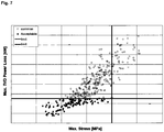
- Fig. 7 respecting crankshaft torsional stress and torsional vibration damper power loss limits, 117 firing sequences candidates were kept for further investigations.
- crankshaft main bearings wear and fatigue of crankshaft main bearings depends on many aspects and has to be assessed carefully during the development of the base engine.
- the firing sequence affects the main bearing load in several ways. Besides the contribution from cylinder pressure, the bearing peak force depends also on the mass balancing, which is determined by the crank star, and is thus depending on the chosen firing sequence. Additionally, a considerable bearing force is induced by the dynamic torsion of the crankshaft. The firing sequence decides whether this additional load is superposed in-phase with the peak firing load, or not. Furthermore, regarding thermal load of a bearing, it is advantageous to keep a certain time interval between two consecutive peak loads in order to allow for sufficient cooling by oil flushing. A simple measure for this is to regard the maximum number of consecutive peak loads on a bearing.
- Bearing Load Index While at engines with a V-angle smaller than the crank star angle, there can exist up to 4 peak loads in a series. In Fig. 8 , from the remaining 117 candidates, 30 of them correspond to advantageous bearing load index.
- the filling of a cylinder depends strongly on the local pressure at the corresponding location in the intake manifold during the intake phase. This, however, depends strongly on the spatial distance which is kept to the previously fired cylinder on the same intake manifold. In order to achieve a well-balanced filling between the cylinders, it is recommended to keep a sufficiently large distance between consecutively fired cylinders on the same intake manifold. At the exhaust side, the situation is more complex, as the wave propagation of the exhaust gas can play an important role.
- a further critical point is the axial acceleration of the torsional vibration damper. Both structural fatigue strength as well as function of a viscous damper require to limit the axial accelerations to a certain value. Under resonance conditions, this limit is exceeded significantly, see Fig. 11 (left). For the new crank star, the axial acceleration is reduced by more than 30%, and the given limit is respected all over the engine speed range.
- Fig. 14 were determined for engines with counter-clockwise rotation, and the firing sequences shown in Fig. 15 were obtained for engines with clockwise rotation.
- Fig. 14 and 15 further indicate the corresponding crank stars from Fig. 12 and 13 , respectively.
Landscapes
- Engineering & Computer Science (AREA)
- General Engineering & Computer Science (AREA)
- Mechanical Engineering (AREA)
- Physics & Mathematics (AREA)
- Acoustics & Sound (AREA)
- Aviation & Aerospace Engineering (AREA)
- Chemical & Material Sciences (AREA)
- Combustion & Propulsion (AREA)
- Ocean & Marine Engineering (AREA)
- Shafts, Cranks, Connecting Bars, And Related Bearings (AREA)
Claims (15)
- Viertakt-Hubkolbenmotor in V-Bauweise mit 16 Zylindern, mit Drehrichtung im oder entgegen dem Uhrzeigersinn, mit einer Kurbelwelle sowie einem Drehschwingungsdämpfer und einem Schwungrad, welche auf der Kurbelwelle angeordnet sind, wobei die Kurbelwelle 8 einen Kurbelstern bildende Kröpfungen aufweist, wobei die Pleuel der beiden Zylinder eines V-Segments jeweils mit derselben Kröpfung verbunden sind, wobei der Kurbelstern zentralsymmetrisch oder quasi-zentralsymmetrisch aufgebaut ist, wobei die Kröpfungen C1 bis C8 von der Schwungradseite aus gesehen in Drehrichtung eine der folgenden Winkelabfolgen aufweisen, wobei die Kröpfungen von der Schwungradseite beginnend mit C1 bis C8 durchnummeriert sind:i) C1,C8 - C2,C7 - C3,C6 - C4,C5ii) C1,C8 - C4,C5 - C3,C6 - C2,C7iii) C1,C8 - C3,C6 - C4,C5 - C2,C7.
- Viertakt-Hubkolbenmotor in V-Bauweise nach Anspruch 1, mit Drehrichtung entgegen dem Uhrzeigersinn, mit einer Zündfolgensteuerung, welche die Zylinder A1 bis A8 und B1 bis B8 in mindestens einer der folgenden Zündfolgen zündet, wobei die Drehrichtung sowie die Zylindernummerierung nach DIN ISO 1204 definiert sind:a) A1-B7-A2-B6-A3-B5-A5-B 1-A8-B2-A7-B3-A6-B4-A4-B8b) A1-B7-A2-B6-A6-B4-A5-B1-A8-B2-A7-B3-A3-B5-A4-B8c) A1-B7-A2-B5-A4-B3-A6-B1-A8-B2-A7-B4-A5-B6-A3-B8d) A1-B4-A4-B6-A3-B7-A2-B8-A8-B5-A5-B3-A6-B2-A7-B1e) A1-B5-A5-B3-A6-B2-A7-B1-A8-B4-A4-B6-A3-B7-A2-B8
- Viertakt-Hubkolbenmotor in V-Bauweise nach Anspruch 1, mit Drehrichtung im Uhrzeigersinn, mit einer Zündfolgensteuerung, welche die Zylinder A1 bis A8 und B1 bis B8 in mindestens einer der folgenden Zündfolgen zündet, wobei die Drehrichtung sowie die Zylindernummerierung nach DIN ISO 1204 definiert sind:a) B1-A7-B2-A6-B3-A5-B5-A1-B8-A2-B7-A3-B6-A4-B4-A8b) B1-A7-B2-A6-B6-A4-B5-A1-B8-A2-B7-A3-B3-A5-B4-A8c) B1-A7-B2-A5-B4-A3-B6-A1-B8-A2-B7-A4-B5-A6-B3-A8d) B1-A4-B4-A6-B3-A7-B2-A8-B8-A5-B5-A3-B6-A2-B7-A1e) B1-A5-B5-A3-B6-A2-B7-A1-B8-A4-B4-A6-B3-A7-B2-A8.
- Viertakt-Hubkolbenmotor in V-Bauweise nach Anspruch 2 oder 3, wobei eine der folgenden Kombinationen aus Zündfolge und Kurbelstern vorliegt:- Kurbelstern i), eine der Zündfolgen d oder e- Kurbelstern ii), eine der Zündfolgen a oder b- Kurbelstern iii), Zündfolge c.
- Viertakt-Hubkolbenmotor in V-Bauweise nach einem der vorangegangenen Ansprüche, wobei der V-Winkel zwischen 40° und 80° beträgt, bevorzugt zwischen 50° und 70°, besonders bevorzugt zwischen 55° und 65°, ganz besonders bevorzugt 60° beträgt.
- Viertakt-Hubkolbenmotor in V-Bauweise nach einem der vorangegangenen Ansprüche, wobei die Winkeldifferenz zwischen zwei Kröpfungen, welche den gleichen Abstand zur Mittelebene der Kurbelwelle aufweisen, kleiner 5° ist, bevorzugt kleiner 3°, besonders bevorzugt kleiner 1°,
und/oder wobei auf beiden Kurbelwellenhälften der Winkelabstand zwischen zwei aufeinanderfolgenden Kröpfungen jeweils zwischen 80° und 100° oder zwischen 170° und 190° beträgt, bevorzugt zwischen 85° und 95° oder zwischen 175° und 185°, besonders bevorzugt zwischen 89° und 91° oder zwischen 179° und 181°, und ganz besonders bevorzugt 90° oder 180° beträgt, - Viertakt-Hubkolbenmotor in V-Bauweise nach einem der vorstehenden Ansprüche, wobei die Zündfolgen mit Drehrichtung gegen den Uhrzeigersinn einen Winkelabstand zwischen einer Zündung eines Zylinders der B-Bank und einer darauffolgenden Zündung eines Zylinders der A-Bank zwischen 45° und 75°, bevorzugt zwischen 55° und 65°, besonders bevorzugt von 60° aufweisen, und/oder wobei die Zündfolgen mit Drehrichtung gegen den Uhrzeigersinn einen Winkelabstand zwischen einer Zündung eines Zylinders der A-Bank und einer darauffolgenden Zündung eines Zylinders der B-Bank zwischen 15° und 45°, bevorzugt zwischen 25° und 35°, besonders bevorzugt von 30° aufweisen, und/oder wobei die Zündfolgen mit Drehrichtung im Uhrzeigersinn einen Winkelabstand zwischen einer Zündung eines Zylinders der A-Bank und einer darauffolgenden Zündung eines Zylinders der B-Bank zwischen 45° und 75°, bevorzugt zwischen 55° und 65°, besonders bevorzugt von 60° aufweisen, und/oder wobei die Zündfolgen mit Drehrichtung im Uhrzeigersinn einen Winkelabstand zwischen einer Zündung eines Zylinders der B-Bank und einer darauffolgenden Zündung eines Zylinders der A-Bank zwischen 15° und 45°, bevorzugt zwischen 25° und 35°, besonders bevorzugt von 30° aufweisen.
- Viertakt-Hubkolbenmotor in V-Bauweise nach einem der vorangegangenen Ansprüche, wobei die Kurbelwelle aus einem selbstaushärtenden, mikrolegierten Stahl gefertigt ist,
und/oder mit einem Drehschwingungsdämpfer, wobei die Verlustleistung des Drehschwingungsdämpfers bevorzugt weniger als 6 Promille der maximalen Motorleistung beträgt, ferner bevorzugt weniger als 5 Promille, besonders bevorzugt weniger als 3,5 Promille, besonders bevorzugt weniger als 2,5 Promille und ganz besonders bevorzugt weniger als 2 Promille, und/oder wobei der Drehschwingungsdämpfer bevorzugt ein Viskoseöl-Drehschwingungsdämpfer ist, und/oder wobei der Drehschwingungsdämpfer bevorzugt auf der dem Schwungrad gegenüberliegenden Seite der Kurbelwelle angeordnet ist. - Viertakt-Hubkolbenmotor in V-Bauweise nach einem der vorangegangenen Ansprüche, wobei der Hubraum pro Zylinder zwischen 2 l und 15 l beträgt, bevorzugt zwischen 4 l und 12 l, weiter zwischen 5 l und 9 l,
und/oder wobei die Maximalleistung pro Liter Hubraum zwischen 10 kW und 80 kW beträgt, bevorzugt zwischen 20 kW und 50 kW,
und/oder wobei der Motor in einem Drehzahlbereich zwischen 600 und 2100 U/min betreibbar ist,
und/oder wobei der Motor eine Motordrehzahl-Steuerung aufweist, welche den Motor mit einer konstanten Soll-Motordrehzahl betreibt, wobei die konstante Soll-Motordrehzahl bevorzugt durch die Motorsteuerung an Motor- und/oder Lastbedingungen anpassbar ist, und/oder wobei die Soll-Motordrehzahl bevorzugt in einem Drehzahlbereich zwischen 600 und 2100 U/min liegt, und/oder wobei der Motor ein Gasmotor ist und/oder mit einem flüssigen Kraftstoff betreibbar ist, wobei der Motor bevorzugt mit mindestens einem der folgenden Kraftstoffe betreibbar ist: Gas, Diesel, Benzin;
und/oder wobei der Motor eine Direkteinspritzung und/oder eine Hochdruckeinspritzung aufweist,
und/oder wobei der Motor mit einem Diesel- oder einem Otto-Verbrennungsverfahren betreibbar ist,
und/oder wobei die Motorsteuerung so ausgestaltet ist, dass der Motor mit homogenem und/oder geschichteten Verbrennungsverfahren betreibbar ist. - Viertakt-Hubkolbenmotor in V-Bauweise nach einem der vorangegangenen Ansprüche, wobei der Motor ein Saugmotor ist oder eine ein- oder mehrstufige Aufladung aufweist, und/oder wobei alle Zylinder einer Zylinderbank jeweils einen gemeinsamen Ansaugkrümmer und/oder einen gemeinsamen Abgaskrümmer aufweisen, wobei die beiden Abgaskrümmer bevorzugt bezüglich des V-Winkels innen und die Ansaugkrümmer bevorzugt bezüglich des V-Winkels außen angeordnet sind.
- Viertakt-Hubkolbenmotor in V-Bauweise nach einem der vorangegangenen Ansprüche,
wobei der Motor als Antrieb in einer Schwerlast- und/oder Bergbau- und/oder Erdbewegungs- und/oder Transport- und/oder Umschlagmaschine eingesetzt wird, bevorzugt für einen Muldenkipper oder Bagger,
und/oder wobei der Motor dazu verwendet wird, einen Generator und/oder eine Hydraulikpumpe anzutreiben, wobei der Generator und/oder die Hydraulikpumpe bevorzugt einen oder mehr Antriebe eines Fahrwerks und/oder Arbeits-Aggregate antreiben, bevorzugt einer Schwerlast- und/oder Bergbau- und/oder Erdbewegungs- und/oder Transport- und/oder Umschlagmaschine, insbesondere für einen Muldenkipper und/oder Bagger,
und/oder wobei der Motor unmittelbar oder über ein mechanisches Getriebe an ein Fahrwerk und/oder Arbeits-Aggregate gekoppelt ist, bevorzugt einer Schwerlast- und/oder Bergbau- und/oder Erdbewegungs- und/oder Transport- und/oder Umschlagmaschine, bevorzugt für einen Muldenkipper und/oder Bagger,
und/oder wobei der Motor als Hauptantrieb in einem Schiff und/oder ein Schienenfahrzeug eingesetzt wird,
und/oder wobei der Motor als Hauptantrieb in militärischen Anwendungen und/oder in der Fluidförderungstechnik und/oder für zur Öl- und/oder Gasförderung und/oder zur Öl- und/oder Gasverarbeitung,
und/oder wobei der Motor für die Stromerzeugung eingesetzt wird, und insbesondere einen Generator antreibt,
und/oder wobei der Motor als Antriebseinheit für eine mobile und/oder stationäre Maschine verwendet wird,
und/oder wobei der Motor und die Last momentensteif und/oder über eine drehelastische Kupplung miteinander verbunden sind. - Maschine mit einem Viertakt-Hubkolbenmotor in V-Bauweise nach einem der vorangegangenen Ansprüche, insbesondere stationäre Maschine oder mobile Maschine, insbesondere Schwerlast- und/oder Bergbau- und/oder Erdbewegungs- und/oder Transport- und/oder Umschlagmaschine, und/oder Schiff und/oder Schienenfahrzeug und/oder schwere Maschine und/oder Fluidfördermaschine und/oder Öl- und/oder Gasfördermaschine und/oder Öl- und/oder Gastransportmaschine und/oder Öl- und/oder Gasverarbeitungsmaschine und/oder Stromerzeugungsaggregat, insbesondere Muldenkipper und/oder Bagger.
- Kurbelwelle für einen Viertakt-Hubkolbenmotor in V-Bauweise nach einem der vorangegangenen Ansprüche.
- Zündfolgensteuerung oder Software für eine Zündfolgensteuerung für einen Viertakt-Hubkolbenmotor in V-Bauweise mit 16 Zylindern nach einem der vorangegangenen Ansprüche, wobei die Zündfolgensteuerung bzw. die Software mindestens eine der in Anspruch 2 und/oder Anspruch 3 angegebenen Zündfolgen implementieren.
- Verfahren zum Betrieb eines Viertakt-Hubkolbenmotors in V-Bauweise mit 16 Zylindern nach einem der vorangegangenen Ansprüche, wobei der Motor mit wenigstens einer der in Anspruch 2 und/oder Anspruch 3 angegebenen Zündfolgen betrieben werden.
Applications Claiming Priority (3)
| Application Number | Priority Date | Filing Date | Title |
|---|---|---|---|
| DE102016008682 | 2016-07-18 | ||
| DE102017000778 | 2017-01-27 | ||
| PCT/EP2017/000878 WO2018015015A1 (en) | 2016-07-18 | 2017-07-18 | V-type 4-stroke internal combustion engine with 16 cylinders |
Publications (2)
| Publication Number | Publication Date |
|---|---|
| EP3485154A1 EP3485154A1 (de) | 2019-05-22 |
| EP3485154B1 true EP3485154B1 (de) | 2020-11-25 |
Family
ID=59485311
Family Applications (1)
| Application Number | Title | Priority Date | Filing Date |
|---|---|---|---|
| EP17745650.6A Active EP3485154B1 (de) | 2016-07-18 | 2017-07-18 | Viertakt-v-verbrennungsmotor mit 16 zylindern |
Country Status (3)
| Country | Link |
|---|---|
| US (1) | US10774736B2 (de) |
| EP (1) | EP3485154B1 (de) |
| WO (1) | WO2018015015A1 (de) |
Families Citing this family (1)
| Publication number | Priority date | Publication date | Assignee | Title |
|---|---|---|---|---|
| DE102020007330B4 (de) * | 2020-12-01 | 2024-07-11 | Anglo Belgian Corporation | Kurbelwelle, Verbrennungsmotor und Steuerung |
Citations (7)
| Publication number | Priority date | Publication date | Assignee | Title |
|---|---|---|---|---|
| US1752713A (en) * | 1927-11-28 | 1930-04-01 | William J Whatley | Internal-combustion engine |
| GB544804A (en) * | 1940-07-22 | 1942-04-28 | Gen Motors Corp | Improved cylinder block for internal combustion engines |
| DE2615742A1 (de) * | 1976-04-10 | 1977-10-27 | Motoren Turbinen Union | Dieselmotor |
| US5544486A (en) * | 1994-12-14 | 1996-08-13 | General Electric Company | Dual outlet turbocharger and twin aftercoolers for a diesel engine |
| US6092016A (en) * | 1999-01-25 | 2000-07-18 | Caterpillar, Inc. | Apparatus and method for diagnosing an engine using an exhaust temperature model |
| US6675639B1 (en) * | 2000-10-25 | 2004-01-13 | Caterpillar Inc | Apparatus and method to detect cylinder faults of internal combustion engines via exhaust temperature monitoring |
| US20130006497A1 (en) * | 2011-06-29 | 2013-01-03 | Electro-Motive Diesel, Inc. | Skip fire fuel injection system and method |
Family Cites Families (11)
| Publication number | Priority date | Publication date | Assignee | Title |
|---|---|---|---|---|
| US1776760A (en) | 1926-12-04 | 1930-09-23 | Jean A H Barkeij | Internal-combustion engine |
| GB551406A (en) | 1941-08-13 | 1943-02-22 | George Sutcliffe Bower | Improvements in or relating to multi-cylinder internal-combustion engines |
| US3748850A (en) | 1971-10-18 | 1973-07-31 | Hanlon & Wilson Co | Exhaust system for a diesel engine |
| US5826563A (en) * | 1997-07-28 | 1998-10-27 | General Electric Company | Diesel engine cylinder skip firing system |
| US6360724B1 (en) * | 2000-05-18 | 2002-03-26 | Brunswick Corporation | Method and apparatus for controlling the power output of a homogenous charge internal combustion engine |
| US7798124B2 (en) * | 2006-09-28 | 2010-09-21 | Woodward Governor Company | Method and system for closed loop combustion control of a lean-burn reciprocating engine using ionization detection |
| US7979193B2 (en) * | 2007-10-15 | 2011-07-12 | Harbert Richard H | Even fire 90°V12 IC engines, fueling and firing sequence controllers, and methods of operation by PS/P technology and IFR compensation by fuel feed control |
| US9726139B2 (en) * | 2012-09-10 | 2017-08-08 | GM Global Technology Operations LLC | System and method for controlling a firing sequence of an engine to reduce vibration when cylinders of the engine are deactivated |
| US9140622B2 (en) * | 2012-09-10 | 2015-09-22 | GM Global Technology Operations LLC | System and method for controlling a firing sequence of an engine to reduce vibration when cylinders of the engine are deactivated |
| US9605601B2 (en) * | 2014-07-07 | 2017-03-28 | Ford Global Technologies, Llc | System and method for selective cylinder deactivation |
| CH711997A1 (de) * | 2016-01-04 | 2017-07-14 | Liebherr Machines Bulle Sa | Viertakt-Hubkolbenmotor in V-Bauweise mit 16 Zylindern. |
-
2017
- 2017-07-18 EP EP17745650.6A patent/EP3485154B1/de active Active
- 2017-07-18 US US16/319,071 patent/US10774736B2/en active Active
- 2017-07-18 WO PCT/EP2017/000878 patent/WO2018015015A1/en not_active Ceased
Patent Citations (7)
| Publication number | Priority date | Publication date | Assignee | Title |
|---|---|---|---|---|
| US1752713A (en) * | 1927-11-28 | 1930-04-01 | William J Whatley | Internal-combustion engine |
| GB544804A (en) * | 1940-07-22 | 1942-04-28 | Gen Motors Corp | Improved cylinder block for internal combustion engines |
| DE2615742A1 (de) * | 1976-04-10 | 1977-10-27 | Motoren Turbinen Union | Dieselmotor |
| US5544486A (en) * | 1994-12-14 | 1996-08-13 | General Electric Company | Dual outlet turbocharger and twin aftercoolers for a diesel engine |
| US6092016A (en) * | 1999-01-25 | 2000-07-18 | Caterpillar, Inc. | Apparatus and method for diagnosing an engine using an exhaust temperature model |
| US6675639B1 (en) * | 2000-10-25 | 2004-01-13 | Caterpillar Inc | Apparatus and method to detect cylinder faults of internal combustion engines via exhaust temperature monitoring |
| US20130006497A1 (en) * | 2011-06-29 | 2013-01-03 | Electro-Motive Diesel, Inc. | Skip fire fuel injection system and method |
Also Published As
| Publication number | Publication date |
|---|---|
| US20190249598A1 (en) | 2019-08-15 |
| US10774736B2 (en) | 2020-09-15 |
| WO2018015015A1 (en) | 2018-01-25 |
| EP3485154A1 (de) | 2019-05-22 |
Similar Documents
| Publication | Publication Date | Title |
|---|---|---|
| US10082074B2 (en) | Four-stroke reciprocating piston engine in a V configuration having 16 cylinders | |
| Yilmaz et al. | An investigation of the effect of counterweight configuration on main bearing load and crankshaft bending stress | |
| CN107848628B (zh) | 用于与螺旋桨驱动式飞行器一起使用的内燃发动机 | |
| EP3485154B1 (de) | Viertakt-v-verbrennungsmotor mit 16 zylindern | |
| US10260412B2 (en) | Four-stroke reciprocating piston engine in a V configuration having 20 cylinders | |
| Arshad et al. | Design optimization for the weight reduction of 2-cylinder reciprocating compressor crankshaft | |
| Rangwala | Reciprocating Machinery Dynamics | |
| EP3571383B1 (de) | Viertakt-v-verbrennungsmotor mit 20 zylindern | |
| Shah et al. | Parametric optimization of four cylinder engine crankshafts | |
| Mokdad et al. | Avoiding Crankshaft Axial Vibrations via Parameter Selection and Simulation | |
| Mendes et al. | Crankshaft torsional vibration analysis in a mid-size diesel engine: simulation and experimental validation | |
| Changming et al. | The investigation of self-balanced property and vibration on the particular crankshaft system for an opposed piston engine | |
| Piancastelli et al. | Dynamic Balancing of 60-Deg V6 Engines With Shared Crankpins Using Asymmetric Alternating Counterweights | |
| Xiang et al. | Three-dimensional coupled vibration failure analysis and structural optimization of the crankshaft of the diesel engine used in the shale gas fracturing truck | |
| Hoag et al. | Cranktrain (Crankshafts, Connecting Rods, and Flywheel) | |
| JP5843922B2 (ja) | 排気静圧管支持構造およびこれを備えた内燃機関 | |
| Chun | Rules for Classification and Construction VI Additional Rules and Guidelines 4 Diesel Engines 2 Calculation of Crankshafts for Internal Combustion Engines Edition 2012 | |
| Smolko | Structural response of the ship hull elements subject to excitation generated by the main engine | |
| Yu et al. | Modal and vibration analysis of reciprocating compressor crankshaft system | |
| Khandelwal et al. | Simulation Driven Design of Crank-train Systems for Elevated In-Cylinder Combustion Pressures for Existing Architecture | |
| Anis | Design analysis and optimization of a crankshaft of a tractor | |
| Stanley et al. | Bearing characteristic parameters to estimate the optimum counterweight mass of a 6-cylinder in-line engine | |
| Manring | Modeling the inertial torque imbalance and foundation forces within an inline internal combustion engine: quantifying the equivalent mass approximation | |
| Gupta | Elasto-multi-body dynamics of internal combustion engines with thin-shell elastohydrodynamic journal bearings | |
| Tuominen | Improved turbocharging system layout for large bore medium speed engine |
Legal Events
| Date | Code | Title | Description |
|---|---|---|---|
| STAA | Information on the status of an ep patent application or granted ep patent |
Free format text: STATUS: UNKNOWN |
|
| STAA | Information on the status of an ep patent application or granted ep patent |
Free format text: STATUS: THE INTERNATIONAL PUBLICATION HAS BEEN MADE |
|
| PUAI | Public reference made under article 153(3) epc to a published international application that has entered the european phase |
Free format text: ORIGINAL CODE: 0009012 |
|
| STAA | Information on the status of an ep patent application or granted ep patent |
Free format text: STATUS: REQUEST FOR EXAMINATION WAS MADE |
|
| 17P | Request for examination filed |
Effective date: 20190214 |
|
| AK | Designated contracting states |
Kind code of ref document: A1 Designated state(s): AL AT BE BG CH CY CZ DE DK EE ES FI FR GB GR HR HU IE IS IT LI LT LU LV MC MK MT NL NO PL PT RO RS SE SI SK SM TR |
|
| AX | Request for extension of the european patent |
Extension state: BA ME |
|
| DAV | Request for validation of the european patent (deleted) | ||
| DAX | Request for extension of the european patent (deleted) | ||
| GRAP | Despatch of communication of intention to grant a patent |
Free format text: ORIGINAL CODE: EPIDOSNIGR1 |
|
| RIC1 | Information provided on ipc code assigned before grant |
Ipc: F16F 15/24 20060101ALI20200508BHEP Ipc: F16C 3/06 20060101ALI20200508BHEP Ipc: F02B 75/18 20060101ALI20200508BHEP Ipc: F02B 75/22 20060101AFI20200508BHEP |
|
| STAA | Information on the status of an ep patent application or granted ep patent |
Free format text: STATUS: GRANT OF PATENT IS INTENDED |
|
| INTG | Intention to grant announced |
Effective date: 20200618 |
|
| GRAS | Grant fee paid |
Free format text: ORIGINAL CODE: EPIDOSNIGR3 |
|
| GRAA | (expected) grant |
Free format text: ORIGINAL CODE: 0009210 |
|
| STAA | Information on the status of an ep patent application or granted ep patent |
Free format text: STATUS: THE PATENT HAS BEEN GRANTED |
|
| AK | Designated contracting states |
Kind code of ref document: B1 Designated state(s): AL AT BE BG CH CY CZ DE DK EE ES FI FR GB GR HR HU IE IS IT LI LT LU LV MC MK MT NL NO PL PT RO RS SE SI SK SM TR |
|
| REG | Reference to a national code |
Ref country code: GB Ref legal event code: FG4D |
|
| REG | Reference to a national code |
Ref country code: CH Ref legal event code: EP |
|
| REG | Reference to a national code |
Ref country code: AT Ref legal event code: REF Ref document number: 1338567 Country of ref document: AT Kind code of ref document: T Effective date: 20201215 |
|
| REG | Reference to a national code |
Ref country code: DE Ref legal event code: R096 Ref document number: 602017028298 Country of ref document: DE |
|
| REG | Reference to a national code |
Ref country code: IE Ref legal event code: FG4D |
|
| REG | Reference to a national code |
Ref country code: FI Ref legal event code: FGE |
|
| REG | Reference to a national code |
Ref country code: CH Ref legal event code: NV Representative=s name: KELLER SCHNEIDER PATENT- UND MARKENANWAELTE AG, CH |
|
| REG | Reference to a national code |
Ref country code: NL Ref legal event code: MP Effective date: 20201125 |
|
| PG25 | Lapsed in a contracting state [announced via postgrant information from national office to epo] |
Ref country code: RS Free format text: LAPSE BECAUSE OF FAILURE TO SUBMIT A TRANSLATION OF THE DESCRIPTION OR TO PAY THE FEE WITHIN THE PRESCRIBED TIME-LIMIT Effective date: 20201125 Ref country code: PT Free format text: LAPSE BECAUSE OF FAILURE TO SUBMIT A TRANSLATION OF THE DESCRIPTION OR TO PAY THE FEE WITHIN THE PRESCRIBED TIME-LIMIT Effective date: 20210325 Ref country code: NO Free format text: LAPSE BECAUSE OF FAILURE TO SUBMIT A TRANSLATION OF THE DESCRIPTION OR TO PAY THE FEE WITHIN THE PRESCRIBED TIME-LIMIT Effective date: 20210225 Ref country code: GR Free format text: LAPSE BECAUSE OF FAILURE TO SUBMIT A TRANSLATION OF THE DESCRIPTION OR TO PAY THE FEE WITHIN THE PRESCRIBED TIME-LIMIT Effective date: 20210226 |
|
| PG25 | Lapsed in a contracting state [announced via postgrant information from national office to epo] |
Ref country code: SE Free format text: LAPSE BECAUSE OF FAILURE TO SUBMIT A TRANSLATION OF THE DESCRIPTION OR TO PAY THE FEE WITHIN THE PRESCRIBED TIME-LIMIT Effective date: 20201125 Ref country code: PL Free format text: LAPSE BECAUSE OF FAILURE TO SUBMIT A TRANSLATION OF THE DESCRIPTION OR TO PAY THE FEE WITHIN THE PRESCRIBED TIME-LIMIT Effective date: 20201125 Ref country code: IS Free format text: LAPSE BECAUSE OF FAILURE TO SUBMIT A TRANSLATION OF THE DESCRIPTION OR TO PAY THE FEE WITHIN THE PRESCRIBED TIME-LIMIT Effective date: 20210325 Ref country code: LV Free format text: LAPSE BECAUSE OF FAILURE TO SUBMIT A TRANSLATION OF THE DESCRIPTION OR TO PAY THE FEE WITHIN THE PRESCRIBED TIME-LIMIT Effective date: 20201125 Ref country code: BG Free format text: LAPSE BECAUSE OF FAILURE TO SUBMIT A TRANSLATION OF THE DESCRIPTION OR TO PAY THE FEE WITHIN THE PRESCRIBED TIME-LIMIT Effective date: 20210225 |
|
| REG | Reference to a national code |
Ref country code: LT Ref legal event code: MG9D |
|
| PG25 | Lapsed in a contracting state [announced via postgrant information from national office to epo] |
Ref country code: HR Free format text: LAPSE BECAUSE OF FAILURE TO SUBMIT A TRANSLATION OF THE DESCRIPTION OR TO PAY THE FEE WITHIN THE PRESCRIBED TIME-LIMIT Effective date: 20201125 |
|
| PG25 | Lapsed in a contracting state [announced via postgrant information from national office to epo] |
Ref country code: RO Free format text: LAPSE BECAUSE OF FAILURE TO SUBMIT A TRANSLATION OF THE DESCRIPTION OR TO PAY THE FEE WITHIN THE PRESCRIBED TIME-LIMIT Effective date: 20201125 Ref country code: SK Free format text: LAPSE BECAUSE OF FAILURE TO SUBMIT A TRANSLATION OF THE DESCRIPTION OR TO PAY THE FEE WITHIN THE PRESCRIBED TIME-LIMIT Effective date: 20201125 Ref country code: EE Free format text: LAPSE BECAUSE OF FAILURE TO SUBMIT A TRANSLATION OF THE DESCRIPTION OR TO PAY THE FEE WITHIN THE PRESCRIBED TIME-LIMIT Effective date: 20201125 Ref country code: CZ Free format text: LAPSE BECAUSE OF FAILURE TO SUBMIT A TRANSLATION OF THE DESCRIPTION OR TO PAY THE FEE WITHIN THE PRESCRIBED TIME-LIMIT Effective date: 20201125 Ref country code: LT Free format text: LAPSE BECAUSE OF FAILURE TO SUBMIT A TRANSLATION OF THE DESCRIPTION OR TO PAY THE FEE WITHIN THE PRESCRIBED TIME-LIMIT Effective date: 20201125 Ref country code: SM Free format text: LAPSE BECAUSE OF FAILURE TO SUBMIT A TRANSLATION OF THE DESCRIPTION OR TO PAY THE FEE WITHIN THE PRESCRIBED TIME-LIMIT Effective date: 20201125 |
|
| REG | Reference to a national code |
Ref country code: DE Ref legal event code: R097 Ref document number: 602017028298 Country of ref document: DE |
|
| PG25 | Lapsed in a contracting state [announced via postgrant information from national office to epo] |
Ref country code: DK Free format text: LAPSE BECAUSE OF FAILURE TO SUBMIT A TRANSLATION OF THE DESCRIPTION OR TO PAY THE FEE WITHIN THE PRESCRIBED TIME-LIMIT Effective date: 20201125 |
|
| PLBE | No opposition filed within time limit |
Free format text: ORIGINAL CODE: 0009261 |
|
| STAA | Information on the status of an ep patent application or granted ep patent |
Free format text: STATUS: NO OPPOSITION FILED WITHIN TIME LIMIT |
|
| PG25 | Lapsed in a contracting state [announced via postgrant information from national office to epo] |
Ref country code: AL Free format text: LAPSE BECAUSE OF FAILURE TO SUBMIT A TRANSLATION OF THE DESCRIPTION OR TO PAY THE FEE WITHIN THE PRESCRIBED TIME-LIMIT Effective date: 20201125 Ref country code: NL Free format text: LAPSE BECAUSE OF FAILURE TO SUBMIT A TRANSLATION OF THE DESCRIPTION OR TO PAY THE FEE WITHIN THE PRESCRIBED TIME-LIMIT Effective date: 20201125 |
|
| 26N | No opposition filed |
Effective date: 20210826 |
|
| PG25 | Lapsed in a contracting state [announced via postgrant information from national office to epo] |
Ref country code: SI Free format text: LAPSE BECAUSE OF FAILURE TO SUBMIT A TRANSLATION OF THE DESCRIPTION OR TO PAY THE FEE WITHIN THE PRESCRIBED TIME-LIMIT Effective date: 20201125 |
|
| PG25 | Lapsed in a contracting state [announced via postgrant information from national office to epo] |
Ref country code: ES Free format text: LAPSE BECAUSE OF FAILURE TO SUBMIT A TRANSLATION OF THE DESCRIPTION OR TO PAY THE FEE WITHIN THE PRESCRIBED TIME-LIMIT Effective date: 20201125 |
|
| PG25 | Lapsed in a contracting state [announced via postgrant information from national office to epo] |
Ref country code: MC Free format text: LAPSE BECAUSE OF FAILURE TO SUBMIT A TRANSLATION OF THE DESCRIPTION OR TO PAY THE FEE WITHIN THE PRESCRIBED TIME-LIMIT Effective date: 20201125 |
|
| REG | Reference to a national code |
Ref country code: BE Ref legal event code: MM Effective date: 20210731 |
|
| PG25 | Lapsed in a contracting state [announced via postgrant information from national office to epo] |
Ref country code: IS Free format text: LAPSE BECAUSE OF FAILURE TO SUBMIT A TRANSLATION OF THE DESCRIPTION OR TO PAY THE FEE WITHIN THE PRESCRIBED TIME-LIMIT Effective date: 20210325 Ref country code: LU Free format text: LAPSE BECAUSE OF NON-PAYMENT OF DUE FEES Effective date: 20210718 |
|
| PG25 | Lapsed in a contracting state [announced via postgrant information from national office to epo] |
Ref country code: IE Free format text: LAPSE BECAUSE OF NON-PAYMENT OF DUE FEES Effective date: 20210718 Ref country code: BE Free format text: LAPSE BECAUSE OF NON-PAYMENT OF DUE FEES Effective date: 20210731 |
|
| PG25 | Lapsed in a contracting state [announced via postgrant information from national office to epo] |
Ref country code: CY Free format text: LAPSE BECAUSE OF FAILURE TO SUBMIT A TRANSLATION OF THE DESCRIPTION OR TO PAY THE FEE WITHIN THE PRESCRIBED TIME-LIMIT Effective date: 20201125 |
|
| PG25 | Lapsed in a contracting state [announced via postgrant information from national office to epo] |
Ref country code: HU Free format text: LAPSE BECAUSE OF FAILURE TO SUBMIT A TRANSLATION OF THE DESCRIPTION OR TO PAY THE FEE WITHIN THE PRESCRIBED TIME-LIMIT; INVALID AB INITIO Effective date: 20170718 |
|
| PG25 | Lapsed in a contracting state [announced via postgrant information from national office to epo] |
Ref country code: MK Free format text: LAPSE BECAUSE OF FAILURE TO SUBMIT A TRANSLATION OF THE DESCRIPTION OR TO PAY THE FEE WITHIN THE PRESCRIBED TIME-LIMIT Effective date: 20201125 |
|
| PG25 | Lapsed in a contracting state [announced via postgrant information from national office to epo] |
Ref country code: TR Free format text: LAPSE BECAUSE OF FAILURE TO SUBMIT A TRANSLATION OF THE DESCRIPTION OR TO PAY THE FEE WITHIN THE PRESCRIBED TIME-LIMIT Effective date: 20201125 |
|
| PG25 | Lapsed in a contracting state [announced via postgrant information from national office to epo] |
Ref country code: MT Free format text: LAPSE BECAUSE OF FAILURE TO SUBMIT A TRANSLATION OF THE DESCRIPTION OR TO PAY THE FEE WITHIN THE PRESCRIBED TIME-LIMIT Effective date: 20201125 |
|
| REG | Reference to a national code |
Ref country code: AT Ref legal event code: UEP Ref document number: 1338567 Country of ref document: AT Kind code of ref document: T Effective date: 20201125 |
|
| PGFP | Annual fee paid to national office [announced via postgrant information from national office to epo] |
Ref country code: FI Payment date: 20250725 Year of fee payment: 9 |
|
| PGFP | Annual fee paid to national office [announced via postgrant information from national office to epo] |
Ref country code: DE Payment date: 20250730 Year of fee payment: 9 |
|
| PGFP | Annual fee paid to national office [announced via postgrant information from national office to epo] |
Ref country code: IT Payment date: 20250729 Year of fee payment: 9 |
|
| PGFP | Annual fee paid to national office [announced via postgrant information from national office to epo] |
Ref country code: GB Payment date: 20250725 Year of fee payment: 9 |
|
| PGFP | Annual fee paid to national office [announced via postgrant information from national office to epo] |
Ref country code: FR Payment date: 20250729 Year of fee payment: 9 Ref country code: AT Payment date: 20250721 Year of fee payment: 9 |
|
| PGFP | Annual fee paid to national office [announced via postgrant information from national office to epo] |
Ref country code: CH Payment date: 20250801 Year of fee payment: 9 |