EP3486476B1 - Entretoise pour une pale de rotor d'une éolienne et procédé de fabrication d'une entretoise - Google Patents
Entretoise pour une pale de rotor d'une éolienne et procédé de fabrication d'une entretoise Download PDFInfo
- Publication number
- EP3486476B1 EP3486476B1 EP18206399.0A EP18206399A EP3486476B1 EP 3486476 B1 EP3486476 B1 EP 3486476B1 EP 18206399 A EP18206399 A EP 18206399A EP 3486476 B1 EP3486476 B1 EP 3486476B1
- Authority
- EP
- European Patent Office
- Prior art keywords
- shear web
- core
- web
- form part
- face
- Prior art date
- Legal status (The legal status is an assumption and is not a legal conclusion. Google has not performed a legal analysis and makes no representation as to the accuracy of the status listed.)
- Revoked
Links
Images


Classifications
-
- F—MECHANICAL ENGINEERING; LIGHTING; HEATING; WEAPONS; BLASTING
- F03—MACHINES OR ENGINES FOR LIQUIDS; WIND, SPRING, OR WEIGHT MOTORS; PRODUCING MECHANICAL POWER OR A REACTIVE PROPULSIVE THRUST, NOT OTHERWISE PROVIDED FOR
- F03D—WIND MOTORS
- F03D1/00—Wind motors with rotation axis substantially parallel to the air flow entering the rotor
- F03D1/06—Rotors
- F03D1/065—Rotors characterised by their construction elements
- F03D1/0675—Rotors characterised by their construction elements of the blades
-
- F—MECHANICAL ENGINEERING; LIGHTING; HEATING; WEAPONS; BLASTING
- F05—INDEXING SCHEMES RELATING TO ENGINES OR PUMPS IN VARIOUS SUBCLASSES OF CLASSES F01-F04
- F05B—INDEXING SCHEME RELATING TO WIND, SPRING, WEIGHT, INERTIA OR LIKE MOTORS, TO MACHINES OR ENGINES FOR LIQUIDS COVERED BY SUBCLASSES F03B, F03D AND F03G
- F05B2230/00—Manufacture
- F05B2230/30—Manufacture with deposition of material
- F05B2230/31—Layer deposition
-
- F—MECHANICAL ENGINEERING; LIGHTING; HEATING; WEAPONS; BLASTING
- F05—INDEXING SCHEMES RELATING TO ENGINES OR PUMPS IN VARIOUS SUBCLASSES OF CLASSES F01-F04
- F05B—INDEXING SCHEME RELATING TO WIND, SPRING, WEIGHT, INERTIA OR LIKE MOTORS, TO MACHINES OR ENGINES FOR LIQUIDS COVERED BY SUBCLASSES F03B, F03D AND F03G
- F05B2240/00—Components
- F05B2240/20—Rotors
- F05B2240/30—Characteristics of rotor blades, i.e. of any element transforming dynamic fluid energy to or from rotational energy and being attached to a rotor
-
- Y—GENERAL TAGGING OF NEW TECHNOLOGICAL DEVELOPMENTS; GENERAL TAGGING OF CROSS-SECTIONAL TECHNOLOGIES SPANNING OVER SEVERAL SECTIONS OF THE IPC; TECHNICAL SUBJECTS COVERED BY FORMER USPC CROSS-REFERENCE ART COLLECTIONS [XRACs] AND DIGESTS
- Y02—TECHNOLOGIES OR APPLICATIONS FOR MITIGATION OR ADAPTATION AGAINST CLIMATE CHANGE
- Y02E—REDUCTION OF GREENHOUSE GAS [GHG] EMISSIONS, RELATED TO ENERGY GENERATION, TRANSMISSION OR DISTRIBUTION
- Y02E10/00—Energy generation through renewable energy sources
- Y02E10/70—Wind energy
- Y02E10/72—Wind turbines with rotation axis in wind direction
-
- Y—GENERAL TAGGING OF NEW TECHNOLOGICAL DEVELOPMENTS; GENERAL TAGGING OF CROSS-SECTIONAL TECHNOLOGIES SPANNING OVER SEVERAL SECTIONS OF THE IPC; TECHNICAL SUBJECTS COVERED BY FORMER USPC CROSS-REFERENCE ART COLLECTIONS [XRACs] AND DIGESTS
- Y02—TECHNOLOGIES OR APPLICATIONS FOR MITIGATION OR ADAPTATION AGAINST CLIMATE CHANGE
- Y02P—CLIMATE CHANGE MITIGATION TECHNOLOGIES IN THE PRODUCTION OR PROCESSING OF GOODS
- Y02P70/00—Climate change mitigation technologies in the production process for final industrial or consumer products
- Y02P70/50—Manufacturing or production processes characterised by the final manufactured product
Definitions
- the invention relates to a web for a rotor blade of a wind power plant and a method for producing such a web.
- a rotor of a wind energy plant usually comprises a plurality of rotor blades which are connected to a hub of the rotor.
- the rotor is rotated by the wind so that, for example, a generator can be driven via a rotor shaft in order to generate electrical energy.
- the rotor blade should be able to withstand the forces which act on the rotor blade during operation of the wind energy installation.
- the weight of the rotor blade should be as low as possible.
- the rotor blade can be constructed as a shell with a shell part on the suction side and a shell part on the pressure side, between which a cavity is enclosed.
- a web is a component that extends in the cavity of the rotor blade and creates a stabilizing connection between the suction-side shell part and the pressure-side shell part.
- the web can be aligned approximately in the longitudinal direction of the rotor blade and can extend over a substantial part of the length of the rotor blade between the rotor blade root and the rotor blade tip.
- the web has the purpose, among other things, of transferring shear forces from the suction-side shell part into the pressure-side shell part and of keeping the suction-side shell part and the pressure-side shell part at the correct distance from one another, i.e. transmitting tensile forces and pressure forces between the two shell parts.
- the web can be connected to the first shell part via a first web foot and to the second shell part via a second web foot.
- a web body can be arranged between the two web feet.
- the web Since a certain contact surface is required for the connection to a shell part, the web usually has a greater width in the region of the web foot than in the region of the web core. Examples such bridges are in DE 10 2011 082 664 A1 and DE 10 2012 223 707 A1 described.
- document EP 2 881 237 A1 describes a method for producing a web from a shear body and a foot flange, the shear body and the foot flange being connected to one another via fiber layers and resin.
- the invention has for its object to provide a web and a manufacturing method so that the web can be manufactured inexpensively and with the required stability.
- the web according to the invention comprises a web body, in the interior of which a web core is arranged, and a web foot, in the interior of which a molded part is arranged.
- the molded part widens from an end face facing the web core to a support surface.
- the invention has recognized that the web can be inexpensively manufactured with such a web core and such a molded part, with a uniform flow of force resulting within the web.
- the end face of the molded part is dimensioned and arranged in such a way that it covers the width of the web core.
- the end face of the molded part is therefore at least as wide as the web core against which the molded part rests.
- the extent of the end face in the width dimension can be somewhat larger than the width of the web core, for example up to 10% larger, preferably up to 5% larger.
- the height dimension of the web is the direction in which the molded part and the web core lie one above the other.
- the width is aligned perpendicular to it.
- the height and the width together form the cross section of the web.
- the longitudinal direction of the web extends perpendicular to the cross section.
- the web core is held by the molded part at a distance from the support surface, the smallest distance between the web core and the contact surface is at least as large as the smallest distance between the end face and the contact surface.
- the end face of the molded part can comprise a section which lies opposite an apex line of the web core.
- the end face of the molding can Cross section considered include a section that intersects the height dimension perpendicular.
- the end face of the molded part can be designed such that it engages around an end section of the web core.
- An end section is a region of the web core which is oriented in the direction of a shell part of the rotor blade when the web is connected to the rotor blade. In this assembled state, the connection between the bridge core of the bridge and the shell part of the rotor blade is established via the bridge foot.
- the molded part engages around an end section of the web core, the molded part follows the contour of the web core in two lateral directions, starting from an apex of the end section, which is the smallest distance from the shell part of the rotor blade.
- the degrees of connection can be set such that the distance between the degrees of connection and the apex of the web core corresponds to at least 10%, preferably at least 20%, further preferably at least 40% of the thickness of the web core.
- the contact surface of the molded part faces the inner surface of the adjacent shell part of the rotor blade when the web is inserted into the rotor blade.
- An adhesive layer can be arranged between the contact surface of the molded part and the inner surface of the rotor blade, through which the web is connected to the shell part.
- the end face of the molded part and / or the end section of the web core can have the shape of a circular segment in cross section.
- One of the bodies can be curved outwards and the other body can be curved inwards so that the inwards curved body can grip around the outwardly curved body.
- the radius of the outwardly curved segment of the circle can be slightly smaller than the radius of the inwardly curved segment of the circle, so that the circular segments fit into one another, taking into account any layers of fiber material arranged in between. If the circular segment of the inwardly curved body extends over an angle of extends less than 180 °, the angular alignment between the web core and the molded part can be adjusted.
- the circle segment of the inwardly curved body can for example extend over an angle between 90 ° and 170 °, preferably between 120 ° and 160 °. An angle of 360 ° would correspond to a complete circle on this scale.
- the web core is curved outwards and the molded part is curved inwards.
- the circular segment can extend over the entire width of the end face of the molded part. It is also possible that the end face of the molded part has a larger width than the circular segment.
- the end face of the molded part can have the shape of a groove which faces the web core.
- a central region of the channel can lie opposite an apex line of the web core.
- the two legs of the channel can grip around the end section of the web core.
- the end section of the web core can correspond in cross section to the shape of a segment of a circle. In one embodiment, the circular segment extends over 180 ° and connects two mutually parallel side surfaces of the web core.
- the web foot can comprise a support surface, the shape of which is predetermined by the support surface of the molded part.
- the support surface of the web foot can only be separated from the support surface of the molded part by one or more layers of a fiber material.
- the bearing surface of the web base can face the inner surface of the shell part of the rotor blade when the web is mounted in the rotor blade.
- a plane parallel to the inner surface of the shell part can be defined with the support surface.
- the molded part can comprise a first flank, which extends between the support surface and the web core. When viewed in cross section of the web, the first flank can form an angle with the contact surface of between 30 ° and 60 °, preferably between 40 ° and 50 °.
- the molded part can have a rounded edge, which forms the transition between the contact surface and the first flank.
- the radius of the edge rounding can be, for example, between 1 mm and 20 mm.
- the width of the contact surface can be, for example, between 30 mm and 300 mm.
- the distance between the contact surface of the molded part and the apex line of the web core adjacent to the molded part can be, for example, between 5 mm and 150 mm.
- the first flank can have a section that is flat.
- the flat section can extend from the transition region to the contact surface to the core-side end of the first flank.
- the first flank when viewed in cross section, comprises a concave section. Concave means that there is a degree of connection between two points on the flank that the molded part does not intersect.
- the first flank of the molded part can end at its core end in a direction that is parallel to the side surface of the web core, that is to say forms an angle of 0 ° with the side surface of the web.
- An angle of 0 ° is advantageous for the transfer of forces between the web core and the molded part, however, inaccurate manufacturing can easily lead to an offset between the core-side end of the first flank and the side surface of the web core. This is undesirable.
- the angle between the core-side end of the first flank and the side surface of the web core is somewhat larger than 0 °, for example larger than 2 °, preferably larger than 5 °. If the angle is too large, the power transmission deteriorates.
- the angle is therefore preferably not greater than 20 °, more preferably not greater than 10 °.
- the molded part can comprise a second flank, which extends between the support surface and the web core.
- the second flank can have one or more features that are disclosed in connection with the first flank.
- the core-side end of the first flank and the core-side end of the second flank can enclose the end section of the web core between them.
- the transition between the second flank and the contact surface is designed differently than the transition between the first flank and the contact surface.
- the molded part can have a non-rounded edge between the second flank and the contact surface.
- the second flank can end with a flat section or with a concave section in the direction of the bearing surface.
- the contact surface and the second flank can enclose an angle of between 10 ° and 60 °, preferably between 20 ° and 50 °, for example in the transition region.
- the web core and the molded part are clad in one or more layers of a fiber material, for example in the form of glass fiber mats.
- the fiber material extends from the first side surface of the web core over the first flank of the molded part and the contact surface of the molded part.
- the transition between the first flank and the contact surface of the molded part is designed in such a way that the fiber material can be guided around without a sharp kink.
- the fiber material can extend beyond the end of the molded part.
- the fiber material can also extend from the second side surface of the web core over the second flank of the molded part. If the fiber material extends beyond the end of the molded part, it can overlap with the end of the fiber material coming from the contact surface.
- the number of layers of fiber material that lies on the side surface of the web core and on the flank of the molded part can be, for example, between 2 and 4. This can apply to the first flank and / or the second flank of the molded part.
- the molding may include one or more layers of fibrous material that extend from the first side surface of the land core around the end portion of the land core to the second side surface of the land core. These layers of the fiber material are therefore in one Intermediate space between the end portion of the web core and the molded part.
- a layer or two Extend layers of the fiber material can end at a distance between 100 mm and 500 mm from the apex line of the bar core.
- the fiber material can be impregnated with a liquid material which, when cured, gives the web stability.
- the curing material can be an epoxy resin, for example.
- the web core can consist of a sandwich core material, the density of which can be, for example, between 40 kg / m 3 and 150 kg / m 3 .
- Foam materials PET, PVC, SAN
- balsa wood for example, have such a low density.
- the sandwich core material can have an elastic modulus between 20 MPa and 200 MPa based on the height dimension of the web.
- the shear strength of the sandwich core material can be, for example, between 0.5 MPa and 2 MPa.
- the molded part can consist of a material whose density and / or whose modulus of elasticity are greater than in the sandwich core material.
- the density of the molded part can be between 150 kg / m 3 and 1200 kg / m 3 , preferably between 150 kg / m 3 and 300 kg / m 3 .
- the modulus of elasticity of the molded part can be between 1000 MPa and 6000 MPa and is therefore of the same order of magnitude as the modulus of elasticity of the adhesive which is used for gluing to the shell part of the rotor blade.
- the molded part consists of high-density polyurethane foam (HD-PU) with a density between 150 kg / m 3 and 300 kg / m 3 .
- the polyurethane foam can be fiber-reinforced. If the molded part consists of pure polyurethane, the density can be of the order of 1000 kg / m 3 .
- the web according to the invention can comprise a first molded part and a second molded part, which are arranged such that they enclose the web core between them.
- the second molded part can have one or more features that are described in connection with the first molded part.
- the molded parts can be aligned such that the first flank of the first molded part is arranged on the same side of the web as the first flank of the second molded part.
- the locations of the fiber material can extend around the entire web and lie flat on the two molded parts or the web core. Apart from overlaps following the first flank of the first molded part and following the first flank of the second molded part, the fiber material can continuously follow the contour of the web.
- the length of the web can be greater than 10 m, preferably greater than 20 m, more preferably greater than 50 m.
- the width of the web core can vary over the length of the web. Width of the web core denotes the dimension oriented perpendicular to the height, the height of the web extending between the two molded parts.
- the width of the ridge may be greater in an area near the leaf root than in an area near the tip of the leaf.
- the web core can be designed in such a way that the width of the web core changes continuously over the length of the web.
- the web core can be designed in such a way that the width of the web core changes suddenly at one or more points. It is then possible to assemble the web core from a plurality of plane-parallel plates of the sandwich core material. In an area in which a plate of reduced thickness abuts a plate of greater thickness, the width of the web core changes abruptly. It is also possible that a compensation ramp is formed in the area of such a transition, which may have a slope between 1: 5 and 1:20, for example.
- the web core can for example comprise plates with a thickness of approx. 10 mm, plates with a thickness of approx. 20 mm and / or plates with a thickness of approx. 30 mm.
- the plate thicknesses used for the web core can be, for example, between 8 mm and 60 mm.
- the molded part preferably extends without interruption over the entire length of the web. If the molded part has a channel for receiving an end section of the web core, the width of the channel can be adapted to the width of the web core. In particular, the width of the trough can taper from an area near the blade root to an area near the blade tip. The The taper can be designed continuously, that is, without sudden changes in the width of the channel. It is also possible that the width of the channel changes abruptly to match the thickness changes in the web core.
- the contact surface of the first molded part can be aligned parallel to the contact surface of the second molded part.
- the contact surfaces can enclose a right angle or an angle deviating from the right angle with the height of the web core. It is also possible that the two contact surfaces are not aligned parallel to one another, but instead form an angle with one another, which can be, for example, between 5 ° and 20 °.
- both contact surfaces form an angle of 90 ° or less with the height of the web core.
- both contact surfaces form an angle of 90 ° or more with the height of the web core.
- the first contact surface forms an angle of less than 90 ° and the second contact surface forms an angle of more than 90 ° with the height of the web core.
- the orientation of the two contact surfaces relative to one another can remain unchanged over the length of the web. It is also possible that the orientation of the two contact surfaces changes relative to one another over the length of the web.
- the distance between the two contact surfaces (based on the height of the web) can decrease with increasing distance from the leaf root.
- the invention also relates to a rotor blade for a wind turbine.
- the rotor blade comprises a shell part on the suction side and a shell part on the pressure side.
- the two shell parts are connected to one another at a front edge of the rotor blade and at a rear edge of the rotor blade and enclose a cavity between them.
- a web according to the invention is arranged in the cavity, wherein a support surface of a first molded part of the web is connected to the suction-side shell part and a support surface of a second molded part of the web is connected to the pressure-side shell part.
- the length of the web can extend over at least 80%, preferably at least 90%, of the length of the rotor blade.
- the rotor blade can comprise a plurality of webs which are aligned essentially parallel to one another.
- the rotor blade can be divided into a plurality of chambers by the webs, each chamber being delimited by two webs and by a section of the suction-side shell part and a section of the pressure-side shell part.
- the contact surface of the first molded part can be glued flat to the suction side shell part.
- the bearing surface of the second molded part can be glued flat to the second shell part.
- the invention also relates to a method for producing a web.
- one or more layers of a fiber material are placed in a mold.
- a first molded part and a second molded part are placed on the layers of the fiber material, so that the end faces of the molded parts face one another and that the contact surfaces of the molded parts face away from one another.
- a web core is inserted into the mold so that the web core is arranged between the two end faces of the molded parts.
- the web core is inserted into the mold in such a way that a first end section of the web core is encompassed by the end face of the first molded part and that a second end section of the web core is encompassed by the end face of the second molded part.
- One or more further layers of the fiber material can be inserted into the mold in such a way that the fiber material extends from the second flank of the first molded part over the web core to the second flank of the second molded part.
- the layers can extend beyond the first molded part and / or the second molded part, so that there is an overlap with the layers inserted first.
- a material in particular an epoxy resin, can be introduced into the mold in liquid form and harden in order to fix the web core, the first molded part, the second molded part and the fiber material relative to one another.
- the shape can be free of an undercut so that the finished bar can be easily removed from the mold.
- a further layer of the fiber material is inserted into the mold, which layer extends between the first molded part and the web core and / or between the second molded part and the web core.
- the method can be further developed with further features which are described in connection with the web according to the invention.
- the web can be further developed with further features that are described in connection with the method according to the invention.
- a wind turbine comprises according to Fig. 1 a gondola 14 which is rotatably mounted on a tower 15.
- the gondola carries one in Fig. 1 Invisible rotor shaft to which a rotor 16 is connected.
- the rotor 16 comprises a plurality of rotor blades 17.
- the rotor 16 is rotated by the wind and drives a generator via the rotor shaft to generate electrical energy.
- Each rotor blade 17 extends between a blade root 18, which is connected to a hub 19 of the rotor 16, and a blade tip 20, see Fig. 2 .
- the rotor blade 17 is composed of a suction-side shell part 21 and a pressure-side shell part 22.
- the two shell parts 21, 22 are connected to one another on a front edge 23 and on a rear edge 24 of the rotor blade 17.
- the shell parts 21, 22 enclose a cavity between them, which forms an interior of the rotor blade 17.
- Each bridge 25, 26 comprises a bridge core 27 and two bridge feet 28, 29.
- the bridge feet 28, 29 are wider than the bridge core 27, so that a stable connection to the inner surfaces of the shell parts 21, 22 can be formed via the bridge feet 28, 29 .
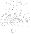
- a corresponding adhesive layer 33 for establishing the connection between the web foot 29 and the inner surface of the shell part 22 is shown in FIG Fig. 4 shown.
- the bridge foot 29 comprises a molded part 30 which extends between a support surface 31 and an end surface 32 which is shaped as a groove.
- the groove 32 opposite the support surface 31 has the shape of a circular segment in cross section, which extends over an angle of approximately 150 °. With the groove 32, the molded part 30 engages around a lower end section 34 of the web core 27.
- the lower end section 34 of the web core 27 is semicircular in cross section and merges into two flat side surfaces 35, 36 of the web core 27.
- the web core 27 can be pivoted within the groove 32 in order to adjust the orientation of the web core 27 relative to the contact surface 31.
- the radius of the lower end section 34 is somewhat smaller than the radius of the groove 32, so that a fiber layer 42 can be passed between the web core 27 and the groove 32.
- the molded part 30 comprises a first flank 37, which extends between the support surface 31 and the groove 32. Viewed in cross section, the first flank 37 is flat and goes with a rounded edge 38 into the bearing surface 31. The other end of the first flank 37 runs straight towards the web core 27 and forms an angle of approximately 45 ° with the side surface 35 of the web core.
- the opposite second flank 39 of the molded part 37 runs in a corresponding manner towards the second side surface 36 of the web core 27.
- the lower end of the second flank 39 includes a non-rounded edge 40 with the contact surface 31.
- the web core 27 and the molded part 30 are embedded in several layers of a glass fiber material, of which in Fig. 4 only one layer 41 is shown.
- the layer 41 extends from the first side surface 35 over the first flank 37 of the molded part 30, the rounded edge 38 and the contact surface 31 to beyond the lower end of the second flank 39.
- the layer 41 also extends from the second side surface 36 of the web core over the second flank 39 of the molded part 30 to beyond the lower edge of the second flank 39. In the area next to the edge 40, the two projecting ends of the layer 41 overlap.
- a further layer 42 of the glass fiber material extends from the first side surface 35 of the web core 27 through the space between the end section 34 and the groove 32 to the second side surface 36 of the Bridge core 27.
- a web according to the invention is produced in the lying state in a shape as shown in Fig. 5 is shown.
- the shape is adjusted to the desired shape of the web 26 by adjusting moving parts 42 and using inserts 43.
- the required number of layers 41 of the glass fiber material is then inserted into the mold, the layers 41 extending over the entire width of the mold.
- Two molded parts 30 are placed on the layers 41 so that the bearing surfaces 31 point outwards.
- the web core 27 is inserted into the mold, so that the two channels 32 of the molded parts 30 are gripped around the two end sections of the web core 27. This arrangement is covered from above with further layers 41 of the glass fiber material.
- the web core 27 consists of light PET foam with a modulus of elasticity of approximately 20 MPa.
- the two molded parts 30 consist of high-strength and high-density polyurethane foam with a modulus of elasticity in the order of 1000 MPa.
- the first flank 37 and the second flank 39 of the molded part 30 have a concave shape.
- the flanks 37, 39 of the molded part 30 taper toward the side surfaces 35, 36 of the web core 27, the upper ends of the flanks 37, 39 enclosing a small angle with the side surfaces 35, 36.
- this results in an approximately continuous transition between the molded part 30 and the web core 27, which is advantageous for the force flow and the stability of the web 27.
- the lower end of the second flank 39 also ends in a curve.
- the layers 41 resting on the second flank 39 and the layers 41 resting on the support surface 31 can merge into the overlap without a step or kink, which is also advantageous for the force flow and the stability of the web 27.
Landscapes
- Engineering & Computer Science (AREA)
- Life Sciences & Earth Sciences (AREA)
- Sustainable Development (AREA)
- Sustainable Energy (AREA)
- Chemical & Material Sciences (AREA)
- Combustion & Propulsion (AREA)
- Mechanical Engineering (AREA)
- General Engineering & Computer Science (AREA)
- Wind Motors (AREA)
Claims (15)
- Entretoise destinée à une pale de rotor (17) d'une éolienne, ladite entretoise comprenant un corps d'entretoise, à l'intérieur duquel est disposé un noyau d'entretoise (27), et un pied d'entretoise (29), à l'intérieur duquel est disposée une partie de moule (30), la partie de moule (30) s'élargissant depuis une face frontale (32) dirigée vers le noyau d'entretoise (27) vers une face d'appui (31), le noyau d'entretoise (27) et la partie de moule (30) étant revêtus d'une matière fibreuse (41) en au moins une couche, caractérisée en ce que la matière fibreuse (41) s'étend depuis une première face latérale (35) du noyau d'entretoise (27) par le biais d'un premier flanc (37) de la partie de moule (30) et de la face d'appui (31) de la partie de moule (30).
- Entretoise selon la revendication 1, caractérisée en ce que la face frontale (32) de la partie de moule (30) couvre la largeur du noyau d'entretoise.
- Entretoise selon la revendication 1 ou 2, caractérisée en ce que la face frontale (32) de la partie de moule (30) s'engage autour d'une portion d'extrémité (34) du noyau d'entretoise (27).
- Entretoise selon l'une des revendications 1 à 3, caractérisée en ce que la face frontale (32) de la partie de moule (30) et la portion d'extrémité (34) du noyau d'entretoise (27) présentent dans une vue en coupe transversale un contour en forme de segment de cercle, l'un des segments de cercle étant incurvé vers l'extérieur et l'autre segment de cercle étant incurvé vers l'intérieur.
- Entretoise selon la revendication 4, caractérisée en ce que le segment de cercle incurvé vers l'intérieur s'étend sur un angle compris entre 90° et 180°, de préférence sur un angle compris entre 120° et 160°.
- Entretoise selon la revendication 4 ou 5, caractérisée en ce que le rayon du segment de cercle incurvé vers l'extérieur est légèrement inférieur au rayon du segment de cercle incurvé vers l'intérieur de sorte que les deux segments de cercle concordent lorsqu'au moins une couche d'une matière fibreuse est disposée entre les segments de cercle.
- Entretoise selon l'une des revendications 1 à 6, caractérisée en ce que la face frontale (32) de la partie de moule est réalisée sous la forme d'une rainure dirigée vers le noyau d'entretoise (27).
- Entretoise selon l'une des revendications 1 à 7, caractérisée par un bord arrondi (38) entre un premier flanc (37) et la face d'appui (31) de la partie de moule (30).
- Entretoise selon l'une des revendications 1 à 8, caractérisée par un bord non-arrondi (40) entre un deuxième flanc (39) et la face d'appui (31) de la partie de moule (30).
- Entretoise selon l'une des revendications 1 à 9, caractérisée en ce que le premier flanc (37) et/ou le deuxième flanc (39) de la partie de moule (30) comprend une portion concave dans une vue en coupe transversale.
- Entretoise selon l'une des revendications 1 à 10, caractérisée en ce qu'une couche de la matière fibreuse (41), appliquée sur la face d'appui (31) de la partie de moule (30), est guidée jusqu'à chevaucher une couche de la matière fibreuse (41) appliquée sur le deuxième flanc (39) de la partie de moule (30).
- Entretoise selon l'une des revendications 1 à 11, caractérisée en ce que, lorsque l'on regarde dans la direction longitudinale de l'entretoise, le noyau d'entretoise (27) présente une variation brusque de largeur et en ce que la rainure (32) de la partie de moule (30) ne présente pas de variation brusque de diamètre.
- Entretoise selon l'une des revendications 1 à 12, caractérisée en ce que le noyau d'entretoise (27) est disposé entre une première partie de moule (30) et une deuxième partie de moule (30).
- Pale de rotor destinée à une éolienne, ladite pale de rotor comprenant une partie de coque côté dépression (21) et une partie de coque côté pression (22), les parties de coque (21, 22) étant reliées entre elles au niveau d'un bord avant (23) et d'un bord arrière (24) de la pale de rotor et renfermant entre elles une cavité, et une entretoise selon l'une des revendications 1 à 13, une première face d'appui de l'entretoise étant reliée à la partie de coque côté dépression (21) et une deuxième face d'appui de l'entretoise étant reliée à la partie de coque côté pression (22).
- Procédé de fabrication d'une entretoise selon l'une des revendications 1 à 13, procédé dans lequel au moins une couche (41) d'une matière fibreuse est insérée dans un moule, dans lequel une première partie de moule (30) et une deuxième partie de moule (30) sont placées sur les couches (41) de la matière fibreuse de telle sorte que les faces frontales (32) des parties de moule (30) soient dirigées l'une vers l'autre et que les faces d'appui (31) des parties de moule (30) soient opposées l'une à l'autre et dans lequel un noyau d'entretoise (27) est inséré dans le moule de telle sorte que le noyau d'entretoise (27) soit disposé entre les faces frontales (32) des parties de moule (30).
Applications Claiming Priority (1)
| Application Number | Priority Date | Filing Date | Title |
|---|---|---|---|
| DE102017010651.7A DE102017010651A1 (de) | 2017-11-17 | 2017-11-17 | Steg für ein Rotorblatt einer Windenergieanlage und Verfahren zum Herstellen eines Stegs |
Publications (2)
| Publication Number | Publication Date |
|---|---|
| EP3486476A1 EP3486476A1 (fr) | 2019-05-22 |
| EP3486476B1 true EP3486476B1 (fr) | 2020-08-05 |
Family
ID=64331718
Family Applications (1)
| Application Number | Title | Priority Date | Filing Date |
|---|---|---|---|
| EP18206399.0A Revoked EP3486476B1 (fr) | 2017-11-17 | 2018-11-15 | Entretoise pour une pale de rotor d'une éolienne et procédé de fabrication d'une entretoise |
Country Status (3)
| Country | Link |
|---|---|
| EP (1) | EP3486476B1 (fr) |
| DE (1) | DE102017010651A1 (fr) |
| ES (1) | ES2821848T3 (fr) |
Families Citing this family (4)
| Publication number | Priority date | Publication date | Assignee | Title |
|---|---|---|---|---|
| CN111098509A (zh) * | 2019-11-18 | 2020-05-05 | 天津中车风电叶片工程有限公司 | 一种风电叶片腹板的粘合结构及粘合方法 |
| EP3885573B1 (fr) | 2020-03-27 | 2022-10-12 | Nordex Energy SE & Co. KG | Pont de rigidification d'une pale de rotor d'éolienne |
| ES2971328T3 (es) | 2020-04-06 | 2024-06-04 | Nordex Energy Spain Sau | Pala de rotor de turbina eólica conuna banda de cizallamiento |
| WO2021228338A1 (fr) * | 2020-05-12 | 2021-11-18 | Vestas Wind Systems A/S | Pale d'éolienne |
Citations (5)
| Publication number | Priority date | Publication date | Assignee | Title |
|---|---|---|---|---|
| US4331723A (en) | 1980-11-05 | 1982-05-25 | The Boeing Company | Advanced composite |
| US20110229333A1 (en) | 2010-03-22 | 2011-09-22 | Repower Systems Ag | Shear web connection |
| EP2881237A1 (fr) | 2013-12-03 | 2015-06-10 | LM WP Patent Holding A/S | Procédé de fabrication d'une bande de cisaillement utilisant une bride de pied de bande préformée |
| US20170058867A1 (en) | 2015-09-01 | 2017-03-02 | General Electric Company | Pultruded components for a shear web of a wind turbine rotor blade |
| WO2019020152A1 (fr) | 2017-07-27 | 2019-01-31 | Vestas Wind Systems A/S | Pied d'âme pour une âme de cisaillement |
Family Cites Families (6)
| Publication number | Priority date | Publication date | Assignee | Title |
|---|---|---|---|---|
| DE102005034621B3 (de) * | 2005-07-19 | 2007-01-11 | Deutsches Zentrum für Luft- und Raumfahrt e.V. | Verbundstruktur und Verfahren zur Herstellung einer Verbundstruktur |
| US8262362B2 (en) * | 2011-06-08 | 2012-09-11 | General Electric Company | Wind turbine blade shear web with spring flanges |
| DE102011082664C5 (de) | 2011-09-14 | 2017-08-10 | Senvion Gmbh | Form zur Herstellung eines Steges und Steg für ein Rotorblatt einer Windenergieanlage |
| WO2013086667A1 (fr) * | 2011-12-12 | 2013-06-20 | General Electric Company | Ensemble d'assemblage de voile de cisaillement d'une pale de turbine éolienne |
| DE102012223707A1 (de) | 2012-12-19 | 2014-06-26 | Sgl Carbon Se | Variable Formvorrichtung zur Herstellung eines T-Stegs für ein Rotorblatt einer Windenergieanlage und ein Verfahren zu deren Herstellung |
| EP3137281B1 (fr) * | 2014-05-01 | 2021-08-04 | LM WP Patent Holding A/S | Système et procédé de fabrication d'une pale d'éolienne |
-
2017
- 2017-11-17 DE DE102017010651.7A patent/DE102017010651A1/de not_active Withdrawn
-
2018
- 2018-11-15 ES ES18206399T patent/ES2821848T3/es active Active
- 2018-11-15 EP EP18206399.0A patent/EP3486476B1/fr not_active Revoked
Patent Citations (5)
| Publication number | Priority date | Publication date | Assignee | Title |
|---|---|---|---|---|
| US4331723A (en) | 1980-11-05 | 1982-05-25 | The Boeing Company | Advanced composite |
| US20110229333A1 (en) | 2010-03-22 | 2011-09-22 | Repower Systems Ag | Shear web connection |
| EP2881237A1 (fr) | 2013-12-03 | 2015-06-10 | LM WP Patent Holding A/S | Procédé de fabrication d'une bande de cisaillement utilisant une bride de pied de bande préformée |
| US20170058867A1 (en) | 2015-09-01 | 2017-03-02 | General Electric Company | Pultruded components for a shear web of a wind turbine rotor blade |
| WO2019020152A1 (fr) | 2017-07-27 | 2019-01-31 | Vestas Wind Systems A/S | Pied d'âme pour une âme de cisaillement |
Also Published As
| Publication number | Publication date |
|---|---|
| ES2821848T3 (es) | 2021-04-27 |
| EP3486476A1 (fr) | 2019-05-22 |
| DE102017010651A1 (de) | 2019-05-23 |
Similar Documents
| Publication | Publication Date | Title |
|---|---|---|
| EP2755815B1 (fr) | Moule et procédé de fabrication d'une entretoise, et entretoise pour une pale de rotor d'une éolienne | |
| DE102011078951C5 (de) | Verfahren zum Herstellen eines Rotorblatts für eine Windenergieanlage | |
| EP2363599B2 (fr) | Pale de rotor pour une éolienne, éolienne et procédé de fabrication d'une pale de rotor | |
| EP3018342B1 (fr) | Procede de fabrication d'une pale de rotor d'eolienne | |
| EP2666615B1 (fr) | Procédé de fabrication d'une demi-coque pour pale de rotor d'éolienne ou d'une pale de rotor d'éolienne et moule de fabrication à cette fin | |
| EP2383092B1 (fr) | Dispositif et partie de moule pour la fabrication de lames de rotor pour éoliennes et procédé de fabrication | |
| EP2273103A2 (fr) | Pale de rotor pour une éolienne et son procédé de fabrication | |
| EP3496936A1 (fr) | Membrure en éléments préfabriqués pourvues de non-tissé et son procédé de production | |
| WO2011101437A1 (fr) | Procédé de production de pales de rotor d'éolienne et d'une pale de rotor d'éolienne | |
| EP2532883A2 (fr) | Composant d'éolienne avec un câble électrique incorporé dans un laminage | |
| EP3486476A1 (fr) | Entretoise pour une pale de rotor d'une éolienne et procédé de fabrication d'une entretoise | |
| DE102015007289A1 (de) | Rotorblatt, Rotorblattgurt und Verfahren zum Herstellen eines Rotorblattgurts | |
| WO2011006562A2 (fr) | Pale rotorique d'une éolienne, procédé de production d'une pale rotorique et paire de courroies pour une pale rotorique | |
| DE102017126276A1 (de) | Verfahren zur Herstellung einer Steg-Gurt-Baugruppe für ein Windenergieanlagenrotorblatt und Steg-Gurt-Baugruppe | |
| EP3604797B1 (fr) | Bande de produit de pultrusion rétrécie et son procédé de fabrication | |
| EP3551438B1 (fr) | Membrure de bord de fuite d'une pale de rotor d'une installation éolienne, pale de rotor et procédé de fabrication d'une membrure de bord de fuite | |
| EP3482918A1 (fr) | Procédé de fabrication d'une entretoise d'une pale de rotor d'une éolienne | |
| EP3634730B1 (fr) | Procédé pour la fabrication d'une pale de rotor pour installations éoliennes | |
| EP3299613B1 (fr) | Pale de rotor ayant un élément de liaison d'extrémité | |
| EP3015702B1 (fr) | Pale de rotor pour une eolienne et procede de fabrication d'une pale de rotor | |
| EP3887670A1 (fr) | Procédé d'introduction d'une courroie de pale de rotor dans une coque de pale de rotor, moule de courroie, pale de rotor ainsi qu'éolienne | |
| DE102022115553A1 (de) | Verfahren zur Herstellung eines Faserverbundbauteils und Faserverbund-Hohlbauteils sowie Windkraftanlage hierzu | |
| EP3653872A1 (fr) | Procédé de fabrication de deux segments de pale de rotor, segment de pale de rotor ainsi que pale de rotor divisée | |
| DE102017126273A1 (de) | Windenergieanlagenrotorblatt mit Steg-Gurt-Verbindung |
Legal Events
| Date | Code | Title | Description |
|---|---|---|---|
| PUAI | Public reference made under article 153(3) epc to a published international application that has entered the european phase |
Free format text: ORIGINAL CODE: 0009012 |
|
| STAA | Information on the status of an ep patent application or granted ep patent |
Free format text: STATUS: THE APPLICATION HAS BEEN PUBLISHED |
|
| AK | Designated contracting states |
Kind code of ref document: A1 Designated state(s): AL AT BE BG CH CY CZ DE DK EE ES FI FR GB GR HR HU IE IS IT LI LT LU LV MC MK MT NL NO PL PT RO RS SE SI SK SM TR |
|
| AX | Request for extension of the european patent |
Extension state: BA ME |
|
| STAA | Information on the status of an ep patent application or granted ep patent |
Free format text: STATUS: REQUEST FOR EXAMINATION WAS MADE |
|
| 17P | Request for examination filed |
Effective date: 20191120 |
|
| RBV | Designated contracting states (corrected) |
Designated state(s): AL AT BE BG CH CY CZ DE DK EE ES FI FR GB GR HR HU IE IS IT LI LT LU LV MC MK MT NL NO PL PT RO RS SE SI SK SM TR |
|
| GRAP | Despatch of communication of intention to grant a patent |
Free format text: ORIGINAL CODE: EPIDOSNIGR1 |
|
| STAA | Information on the status of an ep patent application or granted ep patent |
Free format text: STATUS: GRANT OF PATENT IS INTENDED |
|
| INTG | Intention to grant announced |
Effective date: 20200225 |
|
| GRAS | Grant fee paid |
Free format text: ORIGINAL CODE: EPIDOSNIGR3 |
|
| GRAA | (expected) grant |
Free format text: ORIGINAL CODE: 0009210 |
|
| STAA | Information on the status of an ep patent application or granted ep patent |
Free format text: STATUS: THE PATENT HAS BEEN GRANTED |
|
| AK | Designated contracting states |
Kind code of ref document: B1 Designated state(s): AL AT BE BG CH CY CZ DE DK EE ES FI FR GB GR HR HU IE IS IT LI LT LU LV MC MK MT NL NO PL PT RO RS SE SI SK SM TR |
|
| REG | Reference to a national code |
Ref country code: GB Ref legal event code: FG4D Free format text: NOT ENGLISH |
|
| REG | Reference to a national code |
Ref country code: CH Ref legal event code: EP |
|
| REG | Reference to a national code |
Ref country code: AT Ref legal event code: REF Ref document number: 1299054 Country of ref document: AT Kind code of ref document: T Effective date: 20200815 |
|
| REG | Reference to a national code |
Ref country code: DE Ref legal event code: R096 Ref document number: 502018002109 Country of ref document: DE |
|
| REG | Reference to a national code |
Ref country code: IE Ref legal event code: FG4D Free format text: LANGUAGE OF EP DOCUMENT: GERMAN |
|
| REG | Reference to a national code |
Ref country code: DK Ref legal event code: T3 Effective date: 20201002 |
|
| REG | Reference to a national code |
Ref country code: LT Ref legal event code: MG4D |
|
| REG | Reference to a national code |
Ref country code: NL Ref legal event code: MP Effective date: 20200805 |
|
| PG25 | Lapsed in a contracting state [announced via postgrant information from national office to epo] |
Ref country code: LT Free format text: LAPSE BECAUSE OF FAILURE TO SUBMIT A TRANSLATION OF THE DESCRIPTION OR TO PAY THE FEE WITHIN THE PRESCRIBED TIME-LIMIT Effective date: 20200805 Ref country code: HR Free format text: LAPSE BECAUSE OF FAILURE TO SUBMIT A TRANSLATION OF THE DESCRIPTION OR TO PAY THE FEE WITHIN THE PRESCRIBED TIME-LIMIT Effective date: 20200805 Ref country code: BG Free format text: LAPSE BECAUSE OF FAILURE TO SUBMIT A TRANSLATION OF THE DESCRIPTION OR TO PAY THE FEE WITHIN THE PRESCRIBED TIME-LIMIT Effective date: 20201105 Ref country code: PT Free format text: LAPSE BECAUSE OF FAILURE TO SUBMIT A TRANSLATION OF THE DESCRIPTION OR TO PAY THE FEE WITHIN THE PRESCRIBED TIME-LIMIT Effective date: 20201207 Ref country code: GR Free format text: LAPSE BECAUSE OF FAILURE TO SUBMIT A TRANSLATION OF THE DESCRIPTION OR TO PAY THE FEE WITHIN THE PRESCRIBED TIME-LIMIT Effective date: 20201106 Ref country code: NO Free format text: LAPSE BECAUSE OF FAILURE TO SUBMIT A TRANSLATION OF THE DESCRIPTION OR TO PAY THE FEE WITHIN THE PRESCRIBED TIME-LIMIT Effective date: 20201105 Ref country code: FI Free format text: LAPSE BECAUSE OF FAILURE TO SUBMIT A TRANSLATION OF THE DESCRIPTION OR TO PAY THE FEE WITHIN THE PRESCRIBED TIME-LIMIT Effective date: 20200805 Ref country code: SE Free format text: LAPSE BECAUSE OF FAILURE TO SUBMIT A TRANSLATION OF THE DESCRIPTION OR TO PAY THE FEE WITHIN THE PRESCRIBED TIME-LIMIT Effective date: 20200805 |
|
| PG25 | Lapsed in a contracting state [announced via postgrant information from national office to epo] |
Ref country code: RS Free format text: LAPSE BECAUSE OF FAILURE TO SUBMIT A TRANSLATION OF THE DESCRIPTION OR TO PAY THE FEE WITHIN THE PRESCRIBED TIME-LIMIT Effective date: 20200805 Ref country code: PL Free format text: LAPSE BECAUSE OF FAILURE TO SUBMIT A TRANSLATION OF THE DESCRIPTION OR TO PAY THE FEE WITHIN THE PRESCRIBED TIME-LIMIT Effective date: 20200805 Ref country code: LV Free format text: LAPSE BECAUSE OF FAILURE TO SUBMIT A TRANSLATION OF THE DESCRIPTION OR TO PAY THE FEE WITHIN THE PRESCRIBED TIME-LIMIT Effective date: 20200805 Ref country code: NL Free format text: LAPSE BECAUSE OF FAILURE TO SUBMIT A TRANSLATION OF THE DESCRIPTION OR TO PAY THE FEE WITHIN THE PRESCRIBED TIME-LIMIT Effective date: 20200805 Ref country code: IS Free format text: LAPSE BECAUSE OF FAILURE TO SUBMIT A TRANSLATION OF THE DESCRIPTION OR TO PAY THE FEE WITHIN THE PRESCRIBED TIME-LIMIT Effective date: 20201205 |
|
| REG | Reference to a national code |
Ref country code: ES Ref legal event code: FG2A Ref document number: 2821848 Country of ref document: ES Kind code of ref document: T3 Effective date: 20210427 |
|
| PG25 | Lapsed in a contracting state [announced via postgrant information from national office to epo] |
Ref country code: EE Free format text: LAPSE BECAUSE OF FAILURE TO SUBMIT A TRANSLATION OF THE DESCRIPTION OR TO PAY THE FEE WITHIN THE PRESCRIBED TIME-LIMIT Effective date: 20200805 Ref country code: CZ Free format text: LAPSE BECAUSE OF FAILURE TO SUBMIT A TRANSLATION OF THE DESCRIPTION OR TO PAY THE FEE WITHIN THE PRESCRIBED TIME-LIMIT Effective date: 20200805 Ref country code: RO Free format text: LAPSE BECAUSE OF FAILURE TO SUBMIT A TRANSLATION OF THE DESCRIPTION OR TO PAY THE FEE WITHIN THE PRESCRIBED TIME-LIMIT Effective date: 20200805 Ref country code: SM Free format text: LAPSE BECAUSE OF FAILURE TO SUBMIT A TRANSLATION OF THE DESCRIPTION OR TO PAY THE FEE WITHIN THE PRESCRIBED TIME-LIMIT Effective date: 20200805 |
|
| REG | Reference to a national code |
Ref country code: DE Ref legal event code: R026 Ref document number: 502018002109 Country of ref document: DE |
|
| PLBI | Opposition filed |
Free format text: ORIGINAL CODE: 0009260 |
|
| PLAX | Notice of opposition and request to file observation + time limit sent |
Free format text: ORIGINAL CODE: EPIDOSNOBS2 |
|
| PG25 | Lapsed in a contracting state [announced via postgrant information from national office to epo] |
Ref country code: AL Free format text: LAPSE BECAUSE OF FAILURE TO SUBMIT A TRANSLATION OF THE DESCRIPTION OR TO PAY THE FEE WITHIN THE PRESCRIBED TIME-LIMIT Effective date: 20200805 |
|
| 26 | Opposition filed |
Opponent name: VESTAS WIND SYSTEMS A/S Effective date: 20210505 |
|
| PG25 | Lapsed in a contracting state [announced via postgrant information from national office to epo] |
Ref country code: MC Free format text: LAPSE BECAUSE OF FAILURE TO SUBMIT A TRANSLATION OF THE DESCRIPTION OR TO PAY THE FEE WITHIN THE PRESCRIBED TIME-LIMIT Effective date: 20200805 Ref country code: SK Free format text: LAPSE BECAUSE OF FAILURE TO SUBMIT A TRANSLATION OF THE DESCRIPTION OR TO PAY THE FEE WITHIN THE PRESCRIBED TIME-LIMIT Effective date: 20200805 |
|
| PG25 | Lapsed in a contracting state [announced via postgrant information from national office to epo] |
Ref country code: LU Free format text: LAPSE BECAUSE OF NON-PAYMENT OF DUE FEES Effective date: 20201115 Ref country code: IT Free format text: LAPSE BECAUSE OF FAILURE TO SUBMIT A TRANSLATION OF THE DESCRIPTION OR TO PAY THE FEE WITHIN THE PRESCRIBED TIME-LIMIT Effective date: 20200805 |
|
| RAP2 | Party data changed (patent owner data changed or rights of a patent transferred) |
Owner name: SIEMENS GAMESA RENEWABLE ENERGY SERVICE GMBH |
|
| REG | Reference to a national code |
Ref country code: BE Ref legal event code: MM Effective date: 20201130 |
|
| PG25 | Lapsed in a contracting state [announced via postgrant information from national office to epo] |
Ref country code: SI Free format text: LAPSE BECAUSE OF FAILURE TO SUBMIT A TRANSLATION OF THE DESCRIPTION OR TO PAY THE FEE WITHIN THE PRESCRIBED TIME-LIMIT Effective date: 20200805 |
|
| PLBB | Reply of patent proprietor to notice(s) of opposition received |
Free format text: ORIGINAL CODE: EPIDOSNOBS3 |
|
| PG25 | Lapsed in a contracting state [announced via postgrant information from national office to epo] |
Ref country code: IE Free format text: LAPSE BECAUSE OF NON-PAYMENT OF DUE FEES Effective date: 20201115 |
|
| RAP4 | Party data changed (patent owner data changed or rights of a patent transferred) |
Owner name: SIEMENS GAMESA RENEWABLE ENERGY SERVICE GMBH |
|
| PG25 | Lapsed in a contracting state [announced via postgrant information from national office to epo] |
Ref country code: TR Free format text: LAPSE BECAUSE OF FAILURE TO SUBMIT A TRANSLATION OF THE DESCRIPTION OR TO PAY THE FEE WITHIN THE PRESCRIBED TIME-LIMIT Effective date: 20200805 Ref country code: MT Free format text: LAPSE BECAUSE OF FAILURE TO SUBMIT A TRANSLATION OF THE DESCRIPTION OR TO PAY THE FEE WITHIN THE PRESCRIBED TIME-LIMIT Effective date: 20200805 Ref country code: CY Free format text: LAPSE BECAUSE OF FAILURE TO SUBMIT A TRANSLATION OF THE DESCRIPTION OR TO PAY THE FEE WITHIN THE PRESCRIBED TIME-LIMIT Effective date: 20200805 |
|
| REG | Reference to a national code |
Ref country code: DE Ref legal event code: R081 Ref document number: 502018002109 Country of ref document: DE Owner name: SIEMENS GAMESA RENEWABLE ENERGY SERVICE GMBH, DE Free format text: FORMER OWNER: SENVION GMBH, 22297 HAMBURG, DE |
|
| PG25 | Lapsed in a contracting state [announced via postgrant information from national office to epo] |
Ref country code: MK Free format text: LAPSE BECAUSE OF FAILURE TO SUBMIT A TRANSLATION OF THE DESCRIPTION OR TO PAY THE FEE WITHIN THE PRESCRIBED TIME-LIMIT Effective date: 20200805 |
|
| REG | Reference to a national code |
Ref country code: CH Ref legal event code: PL |
|
| PG25 | Lapsed in a contracting state [announced via postgrant information from national office to epo] |
Ref country code: BE Free format text: LAPSE BECAUSE OF NON-PAYMENT OF DUE FEES Effective date: 20201130 |
|
| PG25 | Lapsed in a contracting state [announced via postgrant information from national office to epo] |
Ref country code: LI Free format text: LAPSE BECAUSE OF NON-PAYMENT OF DUE FEES Effective date: 20211130 Ref country code: CH Free format text: LAPSE BECAUSE OF NON-PAYMENT OF DUE FEES Effective date: 20211130 |
|
| PLCK | Communication despatched that opposition was rejected |
Free format text: ORIGINAL CODE: EPIDOSNREJ1 |
|
| APAH | Appeal reference modified |
Free format text: ORIGINAL CODE: EPIDOSCREFNO |
|
| APBM | Appeal reference recorded |
Free format text: ORIGINAL CODE: EPIDOSNREFNO |
|
| APBP | Date of receipt of notice of appeal recorded |
Free format text: ORIGINAL CODE: EPIDOSNNOA2O |
|
| APBQ | Date of receipt of statement of grounds of appeal recorded |
Free format text: ORIGINAL CODE: EPIDOSNNOA3O |
|
| P01 | Opt-out of the competence of the unified patent court (upc) registered |
Effective date: 20230530 |
|
| REG | Reference to a national code |
Ref country code: GB Ref legal event code: 732E Free format text: REGISTERED BETWEEN 20230727 AND 20230802 |
|
| PGFP | Annual fee paid to national office [announced via postgrant information from national office to epo] |
Ref country code: DE Payment date: 20241128 Year of fee payment: 7 |
|
| REG | Reference to a national code |
Ref country code: AT Ref legal event code: MM01 Ref document number: 1299054 Country of ref document: AT Kind code of ref document: T Effective date: 20231115 |
|
| PGFP | Annual fee paid to national office [announced via postgrant information from national office to epo] |
Ref country code: FR Payment date: 20241126 Year of fee payment: 7 |
|
| PG25 | Lapsed in a contracting state [announced via postgrant information from national office to epo] |
Ref country code: AT Free format text: LAPSE BECAUSE OF NON-PAYMENT OF DUE FEES Effective date: 20231115 |
|
| PGFP | Annual fee paid to national office [announced via postgrant information from national office to epo] |
Ref country code: ES Payment date: 20241218 Year of fee payment: 7 |
|
| PG25 | Lapsed in a contracting state [announced via postgrant information from national office to epo] |
Ref country code: AT Free format text: LAPSE BECAUSE OF NON-PAYMENT OF DUE FEES Effective date: 20231115 |
|
| PLAB | Opposition data, opponent's data or that of the opponent's representative modified |
Free format text: ORIGINAL CODE: 0009299OPPO |
|
| R26 | Opposition filed (corrected) |
Opponent name: VESTAS WIND SYSTEMS A/S Effective date: 20210505 |
|
| PGFP | Annual fee paid to national office [announced via postgrant information from national office to epo] |
Ref country code: DK Payment date: 20250901 Year of fee payment: 8 |
|
| PGFP | Annual fee paid to national office [announced via postgrant information from national office to epo] |
Ref country code: GB Payment date: 20250901 Year of fee payment: 8 |
|
| APBU | Appeal procedure closed |
Free format text: ORIGINAL CODE: EPIDOSNNOA9O |
|
| REG | Reference to a national code |
Ref country code: DE Ref legal event code: R064 Ref document number: 502018002109 Country of ref document: DE Ref country code: DE Ref legal event code: R103 Ref document number: 502018002109 Country of ref document: DE |
|
| RDAF | Communication despatched that patent is revoked |
Free format text: ORIGINAL CODE: EPIDOSNREV1 |
|
| STAA | Information on the status of an ep patent application or granted ep patent |
Free format text: STATUS: PATENT REVOKED |
|
| RDAG | Patent revoked |
Free format text: ORIGINAL CODE: 0009271 |
|
| REG | Reference to a national code |
Ref country code: CH Ref legal event code: N12 Free format text: ST27 STATUS EVENT CODE: U-0-0-N10-N12 (AS PROVIDED BY THE NATIONAL OFFICE) Effective date: 20251119 |
|
| 27W | Patent revoked |
Effective date: 20251111 |
|
| GBPR | Gb: patent revoked under art. 102 of the ep convention designating the uk as contracting state |
Effective date: 20251111 |
|
| PG25 | Lapsed in a contracting state [announced via postgrant information from national office to epo] |
Ref country code: FR Free format text: LAPSE BECAUSE OF NON-PAYMENT OF DUE FEES Effective date: 20251201 |
|
| PGFP | Annual fee paid to national office [announced via postgrant information from national office to epo] |
Ref country code: AT Payment date: 20260410 Year of fee payment: 5 |