EP3486521B1 - Amortisseur de chocs avec actionneur de piston rétractable intégré - Google Patents
Amortisseur de chocs avec actionneur de piston rétractable intégré Download PDFInfo
- Publication number
- EP3486521B1 EP3486521B1 EP18207062.3A EP18207062A EP3486521B1 EP 3486521 B1 EP3486521 B1 EP 3486521B1 EP 18207062 A EP18207062 A EP 18207062A EP 3486521 B1 EP3486521 B1 EP 3486521B1
- Authority
- EP
- European Patent Office
- Prior art keywords
- strut
- shrink
- piston
- chamber
- shock strut
- Prior art date
- Legal status (The legal status is an assumption and is not a legal conclusion. Google has not performed a legal analysis and makes no representation as to the accuracy of the status listed.)
- Active
Links
Images



Classifications
-
- B—PERFORMING OPERATIONS; TRANSPORTING
- B64—AIRCRAFT; AVIATION; COSMONAUTICS
- B64C—AEROPLANES; HELICOPTERS
- B64C25/00—Alighting gear
- B64C25/02—Undercarriages
- B64C25/08—Undercarriages non-fixed, e.g. jettisonable
- B64C25/10—Undercarriages non-fixed, e.g. jettisonable retractable, foldable, or the like
- B64C25/18—Operating mechanisms
- B64C25/22—Operating mechanisms fluid
-
- B—PERFORMING OPERATIONS; TRANSPORTING
- B64—AIRCRAFT; AVIATION; COSMONAUTICS
- B64C—AEROPLANES; HELICOPTERS
- B64C25/00—Alighting gear
- B64C25/32—Alighting gear characterised by elements which contact the ground or similar surface
- B64C25/58—Arrangements or adaptations of shock-absorbers or springs
- B64C25/60—Oleo legs
-
- B—PERFORMING OPERATIONS; TRANSPORTING
- B64—AIRCRAFT; AVIATION; COSMONAUTICS
- B64C—AEROPLANES; HELICOPTERS
- B64C25/00—Alighting gear
- B64C25/02—Undercarriages
- B64C25/08—Undercarriages non-fixed, e.g. jettisonable
- B64C25/10—Undercarriages non-fixed, e.g. jettisonable retractable, foldable, or the like
-
- F—MECHANICAL ENGINEERING; LIGHTING; HEATING; WEAPONS; BLASTING
- F15—FLUID-PRESSURE ACTUATORS; HYDRAULICS OR PNEUMATICS IN GENERAL
- F15B—SYSTEMS ACTING BY MEANS OF FLUIDS IN GENERAL; FLUID-PRESSURE ACTUATORS, e.g. SERVOMOTORS; DETAILS OF FLUID-PRESSURE SYSTEMS, NOT OTHERWISE PROVIDED FOR
- F15B15/00—Fluid-actuated devices for displacing a member from one position to another; Gearing associated therewith
- F15B15/08—Characterised by the construction of the motor unit
- F15B15/14—Characterised by the construction of the motor unit of the straight-cylinder type
- F15B15/149—Fluid interconnections, e.g. fluid connectors, passages
-
- F—MECHANICAL ENGINEERING; LIGHTING; HEATING; WEAPONS; BLASTING
- F15—FLUID-PRESSURE ACTUATORS; HYDRAULICS OR PNEUMATICS IN GENERAL
- F15B—SYSTEMS ACTING BY MEANS OF FLUIDS IN GENERAL; FLUID-PRESSURE ACTUATORS, e.g. SERVOMOTORS; DETAILS OF FLUID-PRESSURE SYSTEMS, NOT OTHERWISE PROVIDED FOR
- F15B15/00—Fluid-actuated devices for displacing a member from one position to another; Gearing associated therewith
- F15B15/08—Characterised by the construction of the motor unit
- F15B15/14—Characterised by the construction of the motor unit of the straight-cylinder type
- F15B15/16—Characterised by the construction of the motor unit of the straight-cylinder type of the telescopic type
-
- F—MECHANICAL ENGINEERING; LIGHTING; HEATING; WEAPONS; BLASTING
- F15—FLUID-PRESSURE ACTUATORS; HYDRAULICS OR PNEUMATICS IN GENERAL
- F15B—SYSTEMS ACTING BY MEANS OF FLUIDS IN GENERAL; FLUID-PRESSURE ACTUATORS, e.g. SERVOMOTORS; DETAILS OF FLUID-PRESSURE SYSTEMS, NOT OTHERWISE PROVIDED FOR
- F15B15/00—Fluid-actuated devices for displacing a member from one position to another; Gearing associated therewith
- F15B15/20—Other details, e.g. assembly with regulating devices
- F15B15/24—Other details, e.g. assembly with regulating devices for restricting the stroke
-
- F—MECHANICAL ENGINEERING; LIGHTING; HEATING; WEAPONS; BLASTING
- F16—ENGINEERING ELEMENTS AND UNITS; GENERAL MEASURES FOR PRODUCING AND MAINTAINING EFFECTIVE FUNCTIONING OF MACHINES OR INSTALLATIONS; THERMAL INSULATION IN GENERAL
- F16F—SPRINGS; SHOCK-ABSORBERS; MEANS FOR DAMPING VIBRATION
- F16F9/00—Springs, vibration-dampers, shock-absorbers, or similarly-constructed movement-dampers using a fluid or the equivalent as damping medium
- F16F9/10—Springs, vibration-dampers, shock-absorbers, or similarly-constructed movement-dampers using a fluid or the equivalent as damping medium using liquid only; using a fluid of which the nature is immaterial
-
- F—MECHANICAL ENGINEERING; LIGHTING; HEATING; WEAPONS; BLASTING
- F16—ENGINEERING ELEMENTS AND UNITS; GENERAL MEASURES FOR PRODUCING AND MAINTAINING EFFECTIVE FUNCTIONING OF MACHINES OR INSTALLATIONS; THERMAL INSULATION IN GENERAL
- F16F—SPRINGS; SHOCK-ABSORBERS; MEANS FOR DAMPING VIBRATION
- F16F9/00—Springs, vibration-dampers, shock-absorbers, or similarly-constructed movement-dampers using a fluid or the equivalent as damping medium
- F16F9/32—Details
- F16F9/43—Filling or drainage arrangements, e.g. for supply of gas
- F16F9/432—Filling or drainage arrangements, e.g. for supply of gas via piston rod sealing or guiding means
-
- F—MECHANICAL ENGINEERING; LIGHTING; HEATING; WEAPONS; BLASTING
- F16—ENGINEERING ELEMENTS AND UNITS; GENERAL MEASURES FOR PRODUCING AND MAINTAINING EFFECTIVE FUNCTIONING OF MACHINES OR INSTALLATIONS; THERMAL INSULATION IN GENERAL
- F16F—SPRINGS; SHOCK-ABSORBERS; MEANS FOR DAMPING VIBRATION
- F16F9/00—Springs, vibration-dampers, shock-absorbers, or similarly-constructed movement-dampers using a fluid or the equivalent as damping medium
- F16F9/32—Details
- F16F9/56—Means for adjusting the length of, or for locking, the spring or damper, e.g. at the end of the stroke
-
- B—PERFORMING OPERATIONS; TRANSPORTING
- B64—AIRCRAFT; AVIATION; COSMONAUTICS
- B64C—AEROPLANES; HELICOPTERS
- B64C25/00—Alighting gear
- B64C25/001—Devices not provided for in the groups B64C25/02 - B64C25/68
- B64C2025/006—Landing gear legs comprising torque arms
-
- B—PERFORMING OPERATIONS; TRANSPORTING
- B64—AIRCRAFT; AVIATION; COSMONAUTICS
- B64C—AEROPLANES; HELICOPTERS
- B64C25/00—Alighting gear
- B64C25/001—Devices not provided for in the groups B64C25/02 - B64C25/68
- B64C2025/008—Comprising means for modifying their length, e.g. for kneeling, for jumping, or for leveling the aircraft
-
- F—MECHANICAL ENGINEERING; LIGHTING; HEATING; WEAPONS; BLASTING
- F16—ENGINEERING ELEMENTS AND UNITS; GENERAL MEASURES FOR PRODUCING AND MAINTAINING EFFECTIVE FUNCTIONING OF MACHINES OR INSTALLATIONS; THERMAL INSULATION IN GENERAL
- F16F—SPRINGS; SHOCK-ABSORBERS; MEANS FOR DAMPING VIBRATION
- F16F2232/00—Nature of movement
- F16F2232/08—Linear
Definitions
- the present disclosure relates to landing gear, and more particularly, to systems and methods for shrink shock struts.
- Shock absorbing devices are used in a wide variety of vehicle suspension systems for controlling motion of the vehicle and its tires with respect to the ground and for reducing transmission of transient forces from the ground to the vehicle.
- Shock absorbing struts are a common component in most aircraft landing gear assemblies. Shock struts control motion of the landing gear, and absorb and damp loads imposed on the gear during landing, taxiing, braking, and takeoff. Struts sometimes need to shrink to fit in a wheel well. Shock struts are known from US 5,908,174 , EP 0461981 , EP 2927117 and EP 2860102 .
- a shock strut comprising a strut cylinder, a strut piston operatively coupled to the strut cylinder, a shrink piston disposed at least partially within and partially extending from the strut cylinder, and a shrink chamber at least partially defined by the shrink piston, wherein the shrink piston comprises a shrink piston head, a sleeve extending from the shrink piston head, and a first mechanical stop.
- the shrink piston is slidably reciprocable within the strut cylinder.
- the strut piston is slidably reciprocable within the shrink piston.
- the shrink piston is in concentric alignment with the strut piston and the strut cylinder.
- the sleeve extends from an open end of the strut cylinder.
- the shock strut further comprises a shrink port disposed in the strut cylinder and in fluid communication with the shrink chamber.
- the strut piston comprises a second mechanical stop configured to mechanically engage the shrink piston in response to the strut piston compressing into the strut cylinder.
- the shrink piston compresses into the strut cylinder in response to the strut piston mechanically engaging the shrink piston.
- the shock strut further comprises an upper bearing disposed between the strut cylinder and the strut piston, wherein the shrink piston head is disposed between the strut cylinder and the strut piston; and a shrink chamber closure disposed between the strut cylinder and the shrink piston.
- the shock strut further comprises a recoil chamber at least partially defined by the upper bearing and the shrink piston, a vent orifice disposed in the shrink piston, a first seal configured to seal the recoil chamber, and a second seal configured to seal the shrink chamber, wherein the vent orifice routes a first fluid leaked from the first seal external the shock strut, and the vent orifice routes a second fluid leaked from the second seal external the shock strut.
- a shock strut arrangement comprising an aircraft hydraulic system, a valve in fluid communication with the aircraft hydraulic system, and a shock strut, comprising a strut cylinder, a strut piston operatively coupled to the strut cylinder, a shrink piston disposed at least partially within the strut cylinder, a shrink chamber at least partially defined by the shrink piston, and a recoil chamber at least partially defined by the shrink piston, wherein the shrink chamber is in fluid communication with the valve.
- the recoil chamber receives a first fluid from the shock strut and the shrink chamber receives a second fluid from the aircraft hydraulic system.
- the shock strut arrangement further comprises a shrink port disposed in the strut cylinder and in fluid communication with the shrink chamber, whereby the shrink chamber receives the second fluid from the aircraft hydraulic system via the shrink port.
- the shock strut arrangement further comprises a first seal configured to seal the recoil chamber, a second seal configured to seal the shrink chamber, and a vent orifice disposed in the shrink piston, the vent orifice comprising an inlet disposed between the first seal and the second seal.
- the vent orifice is configured to route, via the inlet, a first fluid leaked from the recoil chamber externally from the shock strut, and the vent orifice is configured to route, via the inlet, a second fluid leaked from the shrink chamber externally from the shock strut.
- the shock strut arrangement further comprises an upper bearing at least partially defining the recoil chamber, and a shrink chamber closure at least partially defining the shrink chamber.
- the shrink piston comprises a shrink piston head, a sleeve extending from the shrink piston head, and a mechanical stop extending from the sleeve.
- a method for shrinking a shock strut comprising providing a shock strut as defined in claim 1 and moving a fluid into the shrink chamber of the shock strut, wherein the shock strut shrinks in response to the moving.
- the method further comprises moving the fluid from the shrink chamber, wherein the shock strut extends in response to the fluid being moved from the shrink chamber.
- the method further comprises coupling the shock strut to an aircraft hydraulic system such that the shrink chamber is in fluid communication with the aircraft hydraulic system.
- Shock struts may be shrunk to fit in a wheel well.
- Shock struts of the present disclosure utilize an available power source that exists on most aircraft (e.g., a pressurized hydraulic fluid supply) to be utilized effectively to shrink the struts for retraction into a wheel well.
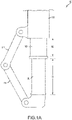
- Shock strut 100 may comprise a strut cylinder 110, a strut piston actuator (strut piston) 120, and a shrink piston 130.
- Strut piston 120 may be operatively coupled to strut cylinder 110 as described herein.
- Strut piston 120 may be operatively coupled to shrink piston 130 as described herein.
- Strut cylinder 110 may be configured to receive strut piston 120 in a manner that allows the two components to telescope together and absorb and damp forces transmitted thereto.
- Shrink piston 130 may be operatively coupled to strut cylinder 110 as described herein.
- Shrink piston 130 may be configured to receive strut piston 120 in a manner that allows the two components to telescope together and absorb and damp forces transmitted thereto.
- Shrink piston 130 may be slidably reciprocable within strut cylinder 110.
- Strut piston 120 may be slidably reciprocable within shrink piston 130.
- a liquid such as a hydraulic fluid and/or oil may be located within strut cylinder 110.
- a gas such as nitrogen or air, may be located within strut cylinder 110.
- Strut cylinder 110 and strut piston 120 may be configured to seal such that fluid contained within strut cylinder 110 is prevented from leaking as strut piston 120 translates relative to strut cylinder 110.
- Strut cylinder 110 and shrink piston 130 may be configured to seal such that fluid contained within strut cylinder 110 is prevented from leaking as shrink piston 130 translates relative to strut cylinder 110.
- shock strut 100 may include an upper torque link arm 112 and a lower torque link arm 114.
- Upper torque link arm 112 may be pivotally coupled to strut cylinder 110.
- Upper torque link arm 112 may be pivotally coupled to lower torque link arm 114.
- Lower torque link arm 114 may be pivotally coupled to strut piston 120.
- Shrink piston 130 extends from strut cylinder 110 by a dimension (also referred to herein as a shrink stroke) 132.
- Strut piston 120 extends from shrink piston 130 by a dimension (also referred to herein as a strut stroke) 122.
- the total stroke of shock strut 100 (e.g., for landing and/or taxiing) may be dimension 122.
- the total stroke of shock strut 100 (e.g., for landing and/or taxiing) may be a combination of dimension 122 and dimension 132.
- the total stroke of shock strut 100 may be determined by the design of shock strut 100.
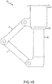
- shock strut 100 is illustrated in a shrunk position, in accordance with various embodiments.
- dimension 132 may be zero in response to shock strut 100 being in the shrunk position.
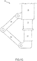
- shock strut 100 is illustrated in a static position, in accordance with various embodiments.
- dimension 132 may be between a maximum value (i.e., dimension 132 illustrated in FIG. 1A ) and a minimum value in response to shock strut 100 being in the static position.
- shrink piston 130 may be partially compressed into strut cylinder 110 in response to shock strut 100 being in the static position.
- dimension 122 may be between a maximum value and a minimum value (i.e., zero as illustrated in FIG. 1C ) in response to shock strut 100 being in the static position.
- strut piston 120 may be partially compressed into shrink piston 130 in response to shock strut 100 being in the static position.
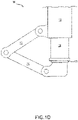
- shock strut 100 is illustrated in a static position, in accordance with various embodiments.
- strut piston 120 may be at a maximum stroke in response to shock strut 100 being in a static position.
- strut piston 120 may be partially compressed into shrink piston 130, as illustrated in FIG. 1C , when shock strut 100 is in the static position, or strut piston 120 may fully compressed into shrink piston 130, as illustrated in FIG. 1D , when shock strut 100 is in the static position.
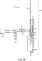
- FIG. 2A elements with like element numbering, as depicted in FIG. 1A , are intended to be the same and will not necessarily be repeated for the sake of clarity.
- shock strut 100 of FIG. 1A may be similar to shock strut 200.
- Shock strut 200 may comprise a strut cylinder 210, a strut piston 220, and a shrink piston actuator (shrink piston) 230.
- Strut cylinder 210, strut piston 220, and shrink piston 230 may be disposed concentric with respect to centerline axis 290.
- Shock strut 200 may further comprise an upper bearing 240.
- Upper bearing 240 may be coupled between strut cylinder 210 and strut piston 220.
- Upper bearing 240 may aid in the translation of strut piston 220 relative to strut cylinder 210.
- Upper bearing 240 may surround strut piston 220.
- Upper bearing 240 may be coupled to and translate with strut piston 220.
- Shock strut 200 may further comprise and a shrink chamber closure 250.
- Shrink chamber closure 250 may be coupled between strut cylinder 210 and shrink piston 230.
- Shrink chamber closure 250 may aid in the translation of shrink piston 230 relative to strut cylinder 210.
- Shrink chamber closure 250 may surround shrink piston 230.
- Shrink chamber closure 250 may comprise a seal.
- Shrink chamber closure 250 may comprise an annular geometry.
- Shrink chamber closure 250 may comprise metal, plastic, rubber, or any other suitable material.
- shrink piston 230 may comprise a shrink piston head 232 and a shrink piston sleeve 234.
- Shrink piston head 232 may engage strut cylinder 210 at an outer surface of shrink piston head 232 and may engage strut piston 220 at an inner surface of shrink piston head 232.
- Shrink piston head 232 may act as a lower shock strut bearing to aid in transferring ground loads from piston 220 into cylinder 210.
- Shrink piston sleeve 234 may extend from shrink piston head 232 in a direction parallel to centerline 290.
- Shrink piston sleeve 234 may extend from an open end 212 of strut cylinder 210.
- Shrink chamber closure 250 may be disposed between strut cylinder 210 and shrink piston sleeve 234.
- a mechanical stop (also referred to herein as a first mechanical stop) 236 may be disposed at the opposite end of shrink piston sleeve 234 from shrink piston head 232.
- Mechanical stop 236 may be configured to engage shrink chamber closure 250.
- Mechanical stop 236 may be configured to engage strut cylinder 210.
- Mechanical stop 236 may prevent shrink piston 230 from compressing into strut cylinder 210 in response to mechanical stop 236 engaging shrink chamber closure 250 and/or strut cylinder 210.
- Mechanical stop 236 may extend radially outward, with respect to centerline 290, from shrink piston sleeve 234.
- Mechanical stop 236 may comprise a tab or a flange, for example.
- FIGs. 2B through FIG. 2E elements with like element numbering, as depicted in FIG. 2A , are intended to be the same and will not necessarily be repeated for the sake of clarity.
- a shrink chamber 260 may be defined between strut cylinder 210 and shrink piston 230.
- shrink chamber 260 may further be defined by shrink chamber closure 250.
- An aperture (also referred to herein as a shrink port) 216 may be disposed in strut cylinder 210, in accordance with various embodiments. Port 216 may be in fluid communication with shrink chamber 260.
- Shrink chamber 260 may receive a hydraulic fluid 262 from a hydraulic fluid supply 286 (e.g., an aircraft hydraulic system), schematically illustrated in FIGs. 2A through FIG. 2D , via port 216.
- Shrink piston 230 may compress into strut cylinder 210 in response to hydraulic fluid moving into shrink chamber 260.
- a hydraulic fluid (also referred to herein as a second fluid) 262 in shrink chamber 260 may force shrink piston 230 and strut piston 220 to compress into strut cylinder 210.
- the overall length of shock strut 200 may decrease in response to shrink piston 230 compressing in strut cylinder 210.
- a valve 280 may be in fluid communication with port 216.
- a check valve 282 and a restrictor 284 may be coupled in parallel between valve 280 and port 216.
- Check valve 282 may be a one-way check valve which prevents hydraulic fluid from traveling from shrink chamber 260 to valve 280, via check valve 282.
- Restrictor 284 may restrict the flow of hydraulic fluid between shrink chamber 260 and valve 280.
- Valve 280 may be configured to disconnect port 216 from a pressure side of hydraulic fluid supply 286 (e.g., see FIG. 2A ).
- Valve 280 may be configured to connect port 216 to the pressure side of hydraulic fluid supply 286 (e.g., see FIG. 2B ).
- Valve 280 may be configured to disconnect port 216 from a return side of hydraulic fluid supply 286 (e.g., see FIG. 2B ). Valve 280 may be configured to connect port 216 to the return side of hydraulic fluid supply 286 (e.g., see FIG. 2A ). Valve 280 may be configured to completely disconnect port 216 from hydraulic fluid supply 286, for example during flight.
- shock strut 200 is illustrated in a static position, in accordance with various embodiments.
- a recoil chamber 265 may be defined between strut cylinder 210 and strut piston 220. Recoil chamber 265 may be further defined between shrink piston 230 and upper bearing 240. Recoil chamber 265 may receive hydraulic fluid from strut cylinder 210.
- a hydraulic fluid (also referred to herein as a first fluid) 217 may enter recoil chamber 265 from strut cylinder chamber 215, for example, via an orifice in upper bearing 240 or an orifice in strut piston 220. Hydraulic fluid 217 in recoil chamber 265 may damp movement of strut piston 220 relative to strut cylinder 210.
- shrink piston head 232 may include an upper seal (also referred to herein as a first seal) 242 and a lower seal (also referred to herein as a second seal) 244.
- Upper seal 242 may seal recoil chamber 265.
- Upper seal 242 may prevent hydraulic fluid 217 from leaking past seal 242.
- Lower seal 244 may seal shrink chamber 260.
- Lower seal 244 may prevent hydraulic fluid 262 from leaking past seal 244.
- hydraulic fluid 217 and hydraulic fluid 262 may be different types of hydraulic fluid.
- hydraulic fluid 217 may comprise a mineral oil and hydraulic fluid 262 may comprise a phosphate ester.
- shrink piston head 232 may include a scraper 246.
- Scraper 246 may be disposed between shrink piston head 232 and strut piston 220. Scraper 246 may scrape against strut piston 220 as strut piston 220 translates relative to shrink piston 230. Scraper 246 may aid in maintaining the outer surface of strut piston 220 clean.
- shrink chamber closure 250 may include a scraper 256. Scraper 256 may be disposed between shrink chamber closure 250 and shrink piston 230. Scraper 256 may scrape against shrink piston 230 as shrink piston 230 translates relative to shrink chamber closure 250. Scraper 256 may aid in maintaining the outer surface of shrink piston 230 clean.
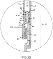
- FIG. 2D elements with like element numbering, as depicted in FIG. 2C , are intended to be the same and will not necessarily be repeated for the sake of clarity.
- shrink piston 330 may be similar to shrink piston 230 of FIG. 2C , except that shrink piston 230 further includes a vent orifice 338.
- shrink piston 330 may include a shrink piston head 332 and a shrink piston sleeve 334.
- a first groove 342 may be disposed in shrink piston head 332.
- Upper seal 242 may be disposed in first groove 342.
- a second groove 344 may be disposed in shrink piston head 332.
- Lower seal 244 may be disposed in second groove 344.
- Vent orifice 338 may be disposed in shrink piston 330.
- Vent orifice 338 may comprise an inlet 302 disposed between first groove 342 and second groove 344.
- the leaked fluid may flow upwards from shrink chamber 260 towards inlet 302 and enter vent orifice 338, via inlet 302.
- This fluid leaked from shrink chamber 260 may exit strut cylinder 210 via outlet 304 of vent orifice 338.
- the leaked fluid may flow downwards from recoil chamber 265 towards inlet 302 and enter vent orifice 338, via inlet 302.
- vent orifice 338 may route hydraulic fluid 262 and/or hydraulic fluid 217 to a location external strut cylinder 210. In this regard, vent orifice 338 may prevent hydraulic fluid 262 from mixing with hydraulic fluid 217.
- shock strut 200 is illustrated in a fully compressed position, in accordance with various embodiments.
- Strut piston 220 may include a mechanical stop (also referred to herein as a second mechanical stop) 226.
- Mechanical stop 226 may comprise a tab or a flange. Mechanical stop 226 may engage with shrink piston 230 in response to shock strut 200 being in the fully compressed position.
- strut piston 220 may mechanically engage shrink piston 230 (e.g., mechanical stop 226 may engage shrink piston 230). Further compression of strut piston 220 may drive shrink piston 230 to compress into strut cylinder 210. As strut piston 220 drives shrink piston 230 into strut cylinder 210, shrink piston 230 may pull hydraulic fluid from hydraulic fluid supply 286 into shrink chamber 260, via open check valve 282 (e.g., in response to shock strut 200 moving from a static position to a fully compressed position).
- shrink piston 230 may pull hydraulic fluid from hydraulic fluid supply 286 into shrink chamber 260, via open check valve 282 (e.g., in response to shock strut 200 moving from a static position to a fully compressed position).
- shrink piston 230 may push hydraulic fluid from shrink chamber 260 to hydraulic fluid supply 286, via restrictor 284 (e.g., in response to shock strut 200 moving from a compressed position to an extended position and in response to check valve 282 becoming closed).
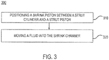
- Method 300 includes positioning a shrink piston between a strut cylinder and a strut piston (step 310).
- Method 300 includes moving a fluid into the shrink chamber (step 320).
- step 310 may include positioning shrink piston 230 between strut cylinder 210 and strut piston 220.
- shrink piston 230 may be positioned around strut piston 220 and then shrink piston 230 and strut piston 220 may be translated, as an assembly, into strut cylinder 210.
- shrink piston 230 and strut piston 220 may be individually positioned within strut cylinder 210.
- Step 320 may include moving hydraulic fluid 262 into shrink chamber 260.
- any of the method or process descriptions may be executed in any order and are not necessarily limited to the order presented.
- any reference to singular includes plural embodiments, and any reference to more than one component or step may include a singular embodiment or step.
- Elements and steps in the figures are illustrated for simplicity and clarity and have not necessarily been rendered according to any particular sequence. For example, steps that may be performed concurrently or in different order are illustrated in the figures to help to improve understanding of embodiments of the present disclosure.
- references to "one embodiment,” “an embodiment,” “various embodiments,” etc. indicate that the embodiment described may include a particular feature, structure, or characteristic, but every embodiment may not necessarily include the particular feature, structure, or characteristic. Moreover, such phrases are not necessarily referring to the same embodiment. Further, when a particular feature, structure, or characteristic is described in connection with an embodiment, it is submitted that it is within the knowledge of one skilled in the art to affect such feature, structure, or characteristic in connection with other embodiments whether or not explicitly described. After reading the description, it will be apparent to one skilled in the relevant art(s) how to implement the disclosure in alternative embodiments.
Landscapes
- Engineering & Computer Science (AREA)
- Mechanical Engineering (AREA)
- General Engineering & Computer Science (AREA)
- Aviation & Aerospace Engineering (AREA)
- Physics & Mathematics (AREA)
- Fluid Mechanics (AREA)
- Actuator (AREA)
- Fluid-Damping Devices (AREA)
Claims (14)
- Amortisseur de chocs, comprenant :un cylindre d'amortisseur (110) ;un piston d'amortisseur (120) couplé fonctionnellement au cylindre d'amortisseur ;un piston rétractable (130) disposé partiellement à l'intérieur et s'étendant partiellement depuis le cylindre d'amortisseur ; etune chambre de rétraction (260) définie au moins partiellement par le piston rétractable ;dans lequel le piston rétractable comprend :une tête de piston rétractable (232) ;un manchon (234) s'étendant depuis la tête du piston rétractable ; etune première butée mécanique (236).
- Amortisseur de chocs selon la revendication 1, dans lequel le piston rétractable (130) peut coulisser en va-et-vient dans le cylindre d'amortisseur (110).
- Amortisseur de chocs selon la revendication 2, dans lequel le piston d'amortisseur (120) peut coulisser en va-et-vient dans le piston rétractable (130).
- Amortisseur de chocs selon la revendication 3, dans lequel le piston rétractable (130) est en alignement concentrique avec le piston d'amortisseur et le cylindre d'amortisseur.
- Amortisseur de chocs selon la revendication 4, dans lequel le manchon (234) s'étend depuis une extrémité ouverte du cylindre d'amortisseur.
- Amortisseur de chocs selon la revendication 5, comprenant en outre un orifice de rétraction (216) disposé dans le cylindre d'amortisseur et en communication fluidique avec la chambre de rétraction.
- Amortisseur de chocs selon une quelconque revendication précédente, dans lequel le piston d'amortisseur comprend une seconde butée mécanique (226) configurée pour venir en prise mécaniquement avec le piston rétractable en réponse à la compression du piston d'amortisseur dans le cylindre d'amortisseur, et de préférence dans lequel le piston rétractable se comprime dans le cylindre d'amortisseur en réponse à la mise en prise du piston d'amortisseur de manière mécanique avec le piston rétractable.
- Amortisseur de chocs selon une quelconque revendication précédente, comprenant en outre :un palier supérieur (240) disposé entre le cylindre d'amortisseur et le piston d'amortisseur, dans lequel la tête de piston rétractable est disposée entre le cylindre d'amortisseur et le piston d'amortisseur ; etune fermeture de chambre de rétraction (250) disposée entre le cylindre d'amortisseur et le piston rétractable.
- Amortisseur de chocs selon la revendication 8, comprenant en outre :une chambre de recul (265) définie au moins partiellement par le palier supérieur et le piston rétractable ;un orifice de ventilation (338) disposé dans le piston rétractable ;un premier joint (242) configuré pour sceller la chambre de recul ; etun second joint (244) configuré pour sceller la chambre de rétraction,dans lequel l'orifice de ventilation achemine un premier fluide fuyant du premier joint vers un emplacement externe à l'amortisseur de chocs ; etl'orifice de ventilation achemine un second fluide fuyant du second joint vers un emplacement externe à l'amortisseur de chocs.
- Agencement d'amortisseur de chocs, comprenant :un système hydraulique d'aéronef ;une valve en communication fluidique avec le système hydraulique d'aéronef ; etun amortisseur de chocs selon l'une quelconque des revendications 1 à 8, comprenant en outre :une chambre de recul (265) définie au moins partiellement par le piston rétractable ; etdans lequel la chambre de rétraction est en communication fluidique avec la valve.
- Agencement d'amortisseur de chocs selon la revendication 10, dans lequel la chambre de recul reçoit un premier fluide depuis l'amortisseur de chocs et la chambre de rétraction reçoit un second fluide depuis le système hydraulique de l'aéronef, et comprenant en outre de préférence un orifice de rétraction (216) disposé dans le cylindre d'amortisseur et en communication fluidique avec la chambre de rétraction, la chambre de rétraction recevant le second fluide depuis le système hydraulique de l'aéronef via l'orifice de rétraction.
- Agencement d'amortisseur de chocs selon la revendication 10 ou 11, comprenant en outre :un premier joint (242) configuré pour sceller la chambre de recul ;un second joint (244) configuré pour sceller la chambre de rétraction ; etun orifice de ventilation (338) disposé dans le piston rétractable, l'orifice de ventilation comprenant une entrée disposée entre le premier joint et le second joint, et de préférence dans lequel l'orifice de ventilation est configuré pour acheminer, via l'entrée, un premier fluide fuyant de la chambre de recul à l'extérieur de l'amortisseur de chocs, etl'orifice de ventilation est configuré pour acheminer, via l'entrée, un second fluide fuyant de la chambre de rétraction vers l'extérieur depuis l'amortisseur de chocs.
- Procédé pour rétrécir l'amortisseur de chocs selon l'une quelconque des revendications 1 à 9, comprenant :la fourniture de l'amortisseur de chocs (110) ;le déplacement d'un fluide dans la chambre de rétraction (260) de l'amortisseur de chocs (110), dans lequel l'amortisseur de chocs se rétrécit en réponse au déplacement.
- Procédé selon la revendication 13, comprenant en outre le déplacement du fluide depuis la chambre de rétraction, dans lequel l'amortisseur de chocs s'étend en réponse au déplacement du fluide depuis la chambre de rétraction, et/ou comprenant en outre le couplage de l'amortisseur de chocs à un système hydraulique d'aéronef de sorte que la chambre de rétraction est en communication fluidique avec le système hydraulique de l'aéronef.
Applications Claiming Priority (1)
| Application Number | Priority Date | Filing Date | Title |
|---|---|---|---|
| US15/816,868 US10717520B2 (en) | 2017-11-17 | 2017-11-17 | Shock strut with integral shrink piston actuator |
Publications (2)
| Publication Number | Publication Date |
|---|---|
| EP3486521A1 EP3486521A1 (fr) | 2019-05-22 |
| EP3486521B1 true EP3486521B1 (fr) | 2022-06-15 |
Family
ID=64362444
Family Applications (1)
| Application Number | Title | Priority Date | Filing Date |
|---|---|---|---|
| EP18207062.3A Active EP3486521B1 (fr) | 2017-11-17 | 2018-11-19 | Amortisseur de chocs avec actionneur de piston rétractable intégré |
Country Status (2)
| Country | Link |
|---|---|
| US (1) | US10717520B2 (fr) |
| EP (1) | EP3486521B1 (fr) |
Family Cites Families (7)
| Publication number | Priority date | Publication date | Assignee | Title |
|---|---|---|---|---|
| EP0461981A3 (en) | 1990-06-13 | 1993-08-04 | Messier Bugatti | Spring-damper unit with variable stroke for a vehicle |
| US5908174A (en) * | 1996-10-31 | 1999-06-01 | Coltec Industries Inc. | Automatic shrink shock strut for an aircraft landing gear |
| CA2808064C (fr) | 2012-05-17 | 2020-02-25 | The Boeing Company | Jambe de suspension hydraulique pour train d'atterrissage partiellement manoeuvre |
| RU2539433C2 (ru) | 2012-10-30 | 2015-01-20 | Российская Федерация, от имени которой выступает Министерство промышленности и торговли Российской Федерации (Департамент авиационной промышленности Минпромторга России) | Убирающаяся опора шасси летательного аппарата |
| US9321525B2 (en) | 2013-10-11 | 2016-04-26 | Goodrich Corporation | Shrink strut landing gear system, method, and apparatus |
| US9481453B2 (en) | 2014-03-31 | 2016-11-01 | Goodrich Corporation | Shrinking system for landing gear |
| US11130564B2 (en) * | 2017-12-21 | 2021-09-28 | Goodrich Corporation | Strut shrink using accumulator as energy source |
-
2017
- 2017-11-17 US US15/816,868 patent/US10717520B2/en active Active
-
2018
- 2018-11-19 EP EP18207062.3A patent/EP3486521B1/fr active Active
Also Published As
| Publication number | Publication date |
|---|---|
| EP3486521A1 (fr) | 2019-05-22 |
| US20190152588A1 (en) | 2019-05-23 |
| US10717520B2 (en) | 2020-07-21 |
Similar Documents
| Publication | Publication Date | Title |
|---|---|---|
| EP2860102B1 (fr) | Système de train d'atterrissage à entretoise rétractable | |
| US9771147B2 (en) | Shrink strut landing gear system, method, and apparatus | |
| EP2179921B1 (fr) | Système de jambe amortisseur retractable pour train d'atterrissage relevable | |
| EP3498601B1 (fr) | Ensemble de verrous de jambe d'amortisseur | |
| EP3578847B1 (fr) | Entretien d'un amortisseur à fluide/gaz mélangé à deux étages | |
| US9541151B2 (en) | Dual stage shock strut with removable second stage fluid chamber | |
| US6279854B1 (en) | Combined damper and truck positioner for landing gear | |
| EP3012481B1 (fr) | Piston à tête z pour amortisseurs à chambres doubles | |
| EP3345828B1 (fr) | Jambe à amortisseur à deux étages permettant une charge de compression initiale faible | |
| US20120018573A1 (en) | Compact shimmy damper for aircraft landing gear | |
| US12552522B2 (en) | Shock strut variable-area metering unit | |
| EP3486521B1 (fr) | Amortisseur de chocs avec actionneur de piston rétractable intégré | |
| EP3418190B1 (fr) | Train d'atterrissage en semi-porte-à-faux actionné par un amortisseur de charge d'articulation externe pour amélioration du décollage | |
| US7967119B2 (en) | Telescopic member having an overridable internal abutment | |
| EP3508420B1 (fr) | Systèmes hydrauliques permettant de rétracter des trains d'atterrissage | |
| US12384530B2 (en) | Self-sustaining shimmy damper system for landing gear shock strut assemblies | |
| US10766606B2 (en) | Semi cantilevered landing gear actuated by an external articulating load damper for improved take-off | |
| EP4198334A1 (fr) | Système amortisseur de shimmy auto-entretenu pour ensembles d'amortisseurs de train d'atterrissage |
Legal Events
| Date | Code | Title | Description |
|---|---|---|---|
| PUAI | Public reference made under article 153(3) epc to a published international application that has entered the european phase |
Free format text: ORIGINAL CODE: 0009012 |
|
| STAA | Information on the status of an ep patent application or granted ep patent |
Free format text: STATUS: THE APPLICATION HAS BEEN PUBLISHED |
|
| AK | Designated contracting states |
Kind code of ref document: A1 Designated state(s): AL AT BE BG CH CY CZ DE DK EE ES FI FR GB GR HR HU IE IS IT LI LT LU LV MC MK MT NL NO PL PT RO RS SE SI SK SM TR |
|
| AX | Request for extension of the european patent |
Extension state: BA ME |
|
| STAA | Information on the status of an ep patent application or granted ep patent |
Free format text: STATUS: REQUEST FOR EXAMINATION WAS MADE |
|
| 17P | Request for examination filed |
Effective date: 20191120 |
|
| RBV | Designated contracting states (corrected) |
Designated state(s): AL AT BE BG CH CY CZ DE DK EE ES FI FR GB GR HR HU IE IS IT LI LT LU LV MC MK MT NL NO PL PT RO RS SE SI SK SM TR |
|
| STAA | Information on the status of an ep patent application or granted ep patent |
Free format text: STATUS: EXAMINATION IS IN PROGRESS |
|
| 17Q | First examination report despatched |
Effective date: 20200525 |
|
| GRAP | Despatch of communication of intention to grant a patent |
Free format text: ORIGINAL CODE: EPIDOSNIGR1 |
|
| STAA | Information on the status of an ep patent application or granted ep patent |
Free format text: STATUS: GRANT OF PATENT IS INTENDED |
|
| INTG | Intention to grant announced |
Effective date: 20220124 |
|
| GRAS | Grant fee paid |
Free format text: ORIGINAL CODE: EPIDOSNIGR3 |
|
| GRAA | (expected) grant |
Free format text: ORIGINAL CODE: 0009210 |
|
| STAA | Information on the status of an ep patent application or granted ep patent |
Free format text: STATUS: THE PATENT HAS BEEN GRANTED |
|
| AK | Designated contracting states |
Kind code of ref document: B1 Designated state(s): AL AT BE BG CH CY CZ DE DK EE ES FI FR GB GR HR HU IE IS IT LI LT LU LV MC MK MT NL NO PL PT RO RS SE SI SK SM TR |
|
| REG | Reference to a national code |
Ref country code: CH Ref legal event code: EP Ref country code: GB Ref legal event code: FG4D |
|
| REG | Reference to a national code |
Ref country code: IE Ref legal event code: FG4D |
|
| REG | Reference to a national code |
Ref country code: DE Ref legal event code: R096 Ref document number: 602018036719 Country of ref document: DE |
|
| REG | Reference to a national code |
Ref country code: AT Ref legal event code: REF Ref document number: 1498568 Country of ref document: AT Kind code of ref document: T Effective date: 20220715 |
|
| REG | Reference to a national code |
Ref country code: LT Ref legal event code: MG9D |
|
| REG | Reference to a national code |
Ref country code: NL Ref legal event code: MP Effective date: 20220615 |
|
| PG25 | Lapsed in a contracting state [announced via postgrant information from national office to epo] |
Ref country code: SE Free format text: LAPSE BECAUSE OF FAILURE TO SUBMIT A TRANSLATION OF THE DESCRIPTION OR TO PAY THE FEE WITHIN THE PRESCRIBED TIME-LIMIT Effective date: 20220615 Ref country code: NO Free format text: LAPSE BECAUSE OF FAILURE TO SUBMIT A TRANSLATION OF THE DESCRIPTION OR TO PAY THE FEE WITHIN THE PRESCRIBED TIME-LIMIT Effective date: 20220915 Ref country code: LT Free format text: LAPSE BECAUSE OF FAILURE TO SUBMIT A TRANSLATION OF THE DESCRIPTION OR TO PAY THE FEE WITHIN THE PRESCRIBED TIME-LIMIT Effective date: 20220615 Ref country code: HR Free format text: LAPSE BECAUSE OF FAILURE TO SUBMIT A TRANSLATION OF THE DESCRIPTION OR TO PAY THE FEE WITHIN THE PRESCRIBED TIME-LIMIT Effective date: 20220615 Ref country code: GR Free format text: LAPSE BECAUSE OF FAILURE TO SUBMIT A TRANSLATION OF THE DESCRIPTION OR TO PAY THE FEE WITHIN THE PRESCRIBED TIME-LIMIT Effective date: 20220916 Ref country code: FI Free format text: LAPSE BECAUSE OF FAILURE TO SUBMIT A TRANSLATION OF THE DESCRIPTION OR TO PAY THE FEE WITHIN THE PRESCRIBED TIME-LIMIT Effective date: 20220615 Ref country code: BG Free format text: LAPSE BECAUSE OF FAILURE TO SUBMIT A TRANSLATION OF THE DESCRIPTION OR TO PAY THE FEE WITHIN THE PRESCRIBED TIME-LIMIT Effective date: 20220915 |
|
| REG | Reference to a national code |
Ref country code: AT Ref legal event code: MK05 Ref document number: 1498568 Country of ref document: AT Kind code of ref document: T Effective date: 20220615 |
|
| PG25 | Lapsed in a contracting state [announced via postgrant information from national office to epo] |
Ref country code: RS Free format text: LAPSE BECAUSE OF FAILURE TO SUBMIT A TRANSLATION OF THE DESCRIPTION OR TO PAY THE FEE WITHIN THE PRESCRIBED TIME-LIMIT Effective date: 20220615 Ref country code: LV Free format text: LAPSE BECAUSE OF FAILURE TO SUBMIT A TRANSLATION OF THE DESCRIPTION OR TO PAY THE FEE WITHIN THE PRESCRIBED TIME-LIMIT Effective date: 20220615 |
|
| PG25 | Lapsed in a contracting state [announced via postgrant information from national office to epo] |
Ref country code: NL Free format text: LAPSE BECAUSE OF FAILURE TO SUBMIT A TRANSLATION OF THE DESCRIPTION OR TO PAY THE FEE WITHIN THE PRESCRIBED TIME-LIMIT Effective date: 20220615 |
|
| PG25 | Lapsed in a contracting state [announced via postgrant information from national office to epo] |
Ref country code: SM Free format text: LAPSE BECAUSE OF FAILURE TO SUBMIT A TRANSLATION OF THE DESCRIPTION OR TO PAY THE FEE WITHIN THE PRESCRIBED TIME-LIMIT Effective date: 20220615 Ref country code: SK Free format text: LAPSE BECAUSE OF FAILURE TO SUBMIT A TRANSLATION OF THE DESCRIPTION OR TO PAY THE FEE WITHIN THE PRESCRIBED TIME-LIMIT Effective date: 20220615 Ref country code: RO Free format text: LAPSE BECAUSE OF FAILURE TO SUBMIT A TRANSLATION OF THE DESCRIPTION OR TO PAY THE FEE WITHIN THE PRESCRIBED TIME-LIMIT Effective date: 20220615 Ref country code: PT Free format text: LAPSE BECAUSE OF FAILURE TO SUBMIT A TRANSLATION OF THE DESCRIPTION OR TO PAY THE FEE WITHIN THE PRESCRIBED TIME-LIMIT Effective date: 20221017 Ref country code: ES Free format text: LAPSE BECAUSE OF FAILURE TO SUBMIT A TRANSLATION OF THE DESCRIPTION OR TO PAY THE FEE WITHIN THE PRESCRIBED TIME-LIMIT Effective date: 20220615 Ref country code: EE Free format text: LAPSE BECAUSE OF FAILURE TO SUBMIT A TRANSLATION OF THE DESCRIPTION OR TO PAY THE FEE WITHIN THE PRESCRIBED TIME-LIMIT Effective date: 20220615 Ref country code: CZ Free format text: LAPSE BECAUSE OF FAILURE TO SUBMIT A TRANSLATION OF THE DESCRIPTION OR TO PAY THE FEE WITHIN THE PRESCRIBED TIME-LIMIT Effective date: 20220615 Ref country code: AT Free format text: LAPSE BECAUSE OF FAILURE TO SUBMIT A TRANSLATION OF THE DESCRIPTION OR TO PAY THE FEE WITHIN THE PRESCRIBED TIME-LIMIT Effective date: 20220615 |
|
| PG25 | Lapsed in a contracting state [announced via postgrant information from national office to epo] |
Ref country code: PL Free format text: LAPSE BECAUSE OF FAILURE TO SUBMIT A TRANSLATION OF THE DESCRIPTION OR TO PAY THE FEE WITHIN THE PRESCRIBED TIME-LIMIT Effective date: 20220615 Ref country code: IS Free format text: LAPSE BECAUSE OF FAILURE TO SUBMIT A TRANSLATION OF THE DESCRIPTION OR TO PAY THE FEE WITHIN THE PRESCRIBED TIME-LIMIT Effective date: 20221015 |
|
| REG | Reference to a national code |
Ref country code: DE Ref legal event code: R097 Ref document number: 602018036719 Country of ref document: DE |
|
| PG25 | Lapsed in a contracting state [announced via postgrant information from national office to epo] |
Ref country code: AL Free format text: LAPSE BECAUSE OF FAILURE TO SUBMIT A TRANSLATION OF THE DESCRIPTION OR TO PAY THE FEE WITHIN THE PRESCRIBED TIME-LIMIT Effective date: 20220615 |
|
| PLBE | No opposition filed within time limit |
Free format text: ORIGINAL CODE: 0009261 |
|
| STAA | Information on the status of an ep patent application or granted ep patent |
Free format text: STATUS: NO OPPOSITION FILED WITHIN TIME LIMIT |
|
| PG25 | Lapsed in a contracting state [announced via postgrant information from national office to epo] |
Ref country code: DK Free format text: LAPSE BECAUSE OF FAILURE TO SUBMIT A TRANSLATION OF THE DESCRIPTION OR TO PAY THE FEE WITHIN THE PRESCRIBED TIME-LIMIT Effective date: 20220615 |
|
| 26N | No opposition filed |
Effective date: 20230316 |
|
| PG25 | Lapsed in a contracting state [announced via postgrant information from national office to epo] |
Ref country code: SI Free format text: LAPSE BECAUSE OF FAILURE TO SUBMIT A TRANSLATION OF THE DESCRIPTION OR TO PAY THE FEE WITHIN THE PRESCRIBED TIME-LIMIT Effective date: 20220615 |
|
| P01 | Opt-out of the competence of the unified patent court (upc) registered |
Effective date: 20230521 |
|
| PG25 | Lapsed in a contracting state [announced via postgrant information from national office to epo] |
Ref country code: MC Free format text: LAPSE BECAUSE OF FAILURE TO SUBMIT A TRANSLATION OF THE DESCRIPTION OR TO PAY THE FEE WITHIN THE PRESCRIBED TIME-LIMIT Effective date: 20220615 |
|
| REG | Reference to a national code |
Ref country code: CH Ref legal event code: PL |
|
| REG | Reference to a national code |
Ref country code: BE Ref legal event code: MM Effective date: 20221130 |
|
| PG25 | Lapsed in a contracting state [announced via postgrant information from national office to epo] |
Ref country code: LI Free format text: LAPSE BECAUSE OF NON-PAYMENT OF DUE FEES Effective date: 20221130 Ref country code: CH Free format text: LAPSE BECAUSE OF NON-PAYMENT OF DUE FEES Effective date: 20221130 |
|
| PG25 | Lapsed in a contracting state [announced via postgrant information from national office to epo] |
Ref country code: LU Free format text: LAPSE BECAUSE OF NON-PAYMENT OF DUE FEES Effective date: 20221119 |
|
| PG25 | Lapsed in a contracting state [announced via postgrant information from national office to epo] |
Ref country code: IE Free format text: LAPSE BECAUSE OF NON-PAYMENT OF DUE FEES Effective date: 20221119 |
|
| PG25 | Lapsed in a contracting state [announced via postgrant information from national office to epo] |
Ref country code: BE Free format text: LAPSE BECAUSE OF NON-PAYMENT OF DUE FEES Effective date: 20221130 |
|
| PG25 | Lapsed in a contracting state [announced via postgrant information from national office to epo] |
Ref country code: IT Free format text: LAPSE BECAUSE OF FAILURE TO SUBMIT A TRANSLATION OF THE DESCRIPTION OR TO PAY THE FEE WITHIN THE PRESCRIBED TIME-LIMIT Effective date: 20220615 |
|
| PG25 | Lapsed in a contracting state [announced via postgrant information from national office to epo] |
Ref country code: HU Free format text: LAPSE BECAUSE OF FAILURE TO SUBMIT A TRANSLATION OF THE DESCRIPTION OR TO PAY THE FEE WITHIN THE PRESCRIBED TIME-LIMIT; INVALID AB INITIO Effective date: 20181119 |
|
| PG25 | Lapsed in a contracting state [announced via postgrant information from national office to epo] |
Ref country code: CY Free format text: LAPSE BECAUSE OF FAILURE TO SUBMIT A TRANSLATION OF THE DESCRIPTION OR TO PAY THE FEE WITHIN THE PRESCRIBED TIME-LIMIT Effective date: 20220615 |
|
| PG25 | Lapsed in a contracting state [announced via postgrant information from national office to epo] |
Ref country code: MK Free format text: LAPSE BECAUSE OF FAILURE TO SUBMIT A TRANSLATION OF THE DESCRIPTION OR TO PAY THE FEE WITHIN THE PRESCRIBED TIME-LIMIT Effective date: 20220615 |
|
| PG25 | Lapsed in a contracting state [announced via postgrant information from national office to epo] |
Ref country code: TR Free format text: LAPSE BECAUSE OF FAILURE TO SUBMIT A TRANSLATION OF THE DESCRIPTION OR TO PAY THE FEE WITHIN THE PRESCRIBED TIME-LIMIT Effective date: 20220615 |
|
| PG25 | Lapsed in a contracting state [announced via postgrant information from national office to epo] |
Ref country code: MT Free format text: LAPSE BECAUSE OF FAILURE TO SUBMIT A TRANSLATION OF THE DESCRIPTION OR TO PAY THE FEE WITHIN THE PRESCRIBED TIME-LIMIT Effective date: 20220615 |
|
| PG25 | Lapsed in a contracting state [announced via postgrant information from national office to epo] |
Ref country code: BG Free format text: LAPSE BECAUSE OF FAILURE TO SUBMIT A TRANSLATION OF THE DESCRIPTION OR TO PAY THE FEE WITHIN THE PRESCRIBED TIME-LIMIT Effective date: 20220615 |
|
| PG25 | Lapsed in a contracting state [announced via postgrant information from national office to epo] |
Ref country code: BG Free format text: LAPSE BECAUSE OF FAILURE TO SUBMIT A TRANSLATION OF THE DESCRIPTION OR TO PAY THE FEE WITHIN THE PRESCRIBED TIME-LIMIT Effective date: 20220615 |
|
| PGFP | Annual fee paid to national office [announced via postgrant information from national office to epo] |
Ref country code: DE Payment date: 20251022 Year of fee payment: 8 |
|
| PGFP | Annual fee paid to national office [announced via postgrant information from national office to epo] |
Ref country code: GB Payment date: 20251023 Year of fee payment: 8 |
|
| PGFP | Annual fee paid to national office [announced via postgrant information from national office to epo] |
Ref country code: FR Payment date: 20251022 Year of fee payment: 8 |