EP3486528B1 - Regler- und inversionspumpenantriebzahnrad - Google Patents
Regler- und inversionspumpenantriebzahnrad Download PDFInfo
- Publication number
- EP3486528B1 EP3486528B1 EP18205497.3A EP18205497A EP3486528B1 EP 3486528 B1 EP3486528 B1 EP 3486528B1 EP 18205497 A EP18205497 A EP 18205497A EP 3486528 B1 EP3486528 B1 EP 3486528B1
- Authority
- EP
- European Patent Office
- Prior art keywords
- point
- gear
- roll angle
- degrees
- drive gear
- Prior art date
- Legal status (The legal status is an assumption and is not a legal conclusion. Google has not performed a legal analysis and makes no representation as to the accuracy of the status listed.)
- Active
Links
Images

Classifications
-
- G—PHYSICS
- G05—CONTROLLING; REGULATING
- G05D—SYSTEMS FOR CONTROLLING OR REGULATING NON-ELECTRIC VARIABLES
- G05D13/00—Control of linear speed; Control of angular speed; Control of acceleration or deceleration, e.g. of a prime mover
- G05D13/08—Control of linear speed; Control of angular speed; Control of acceleration or deceleration, e.g. of a prime mover without auxiliary power
- G05D13/30—Governors characterised by fluid features in which the speed of a shaft is converted into fluid pressure
-
- B—PERFORMING OPERATIONS; TRANSPORTING
- B64—AIRCRAFT; AVIATION; COSMONAUTICS
- B64D—EQUIPMENT FOR FITTING IN OR TO AIRCRAFT; FLIGHT SUITS; PARACHUTES; ARRANGEMENT OR MOUNTING OF POWER PLANTS OR PROPULSION TRANSMISSIONS IN AIRCRAFT
- B64D35/00—Transmitting power from power plants to propellers or rotors; Arrangements of transmissions
-
- F—MECHANICAL ENGINEERING; LIGHTING; HEATING; WEAPONS; BLASTING
- F02—COMBUSTION ENGINES; HOT-GAS OR COMBUSTION-PRODUCT ENGINE PLANTS
- F02C—GAS-TURBINE PLANTS; AIR INTAKES FOR JET-PROPULSION PLANTS; CONTROLLING FUEL SUPPLY IN AIR-BREATHING JET-PROPULSION PLANTS
- F02C7/00—Features, components parts, details or accessories, not provided for in, or of interest apart form groups F02C1/00 - F02C6/00; Air intakes for jet-propulsion plants
- F02C7/32—Arrangement, mounting, or driving, of auxiliaries
-
- F—MECHANICAL ENGINEERING; LIGHTING; HEATING; WEAPONS; BLASTING
- F02—COMBUSTION ENGINES; HOT-GAS OR COMBUSTION-PRODUCT ENGINE PLANTS
- F02C—GAS-TURBINE PLANTS; AIR INTAKES FOR JET-PROPULSION PLANTS; CONTROLLING FUEL SUPPLY IN AIR-BREATHING JET-PROPULSION PLANTS
- F02C7/00—Features, components parts, details or accessories, not provided for in, or of interest apart form groups F02C1/00 - F02C6/00; Air intakes for jet-propulsion plants
- F02C7/36—Power transmission arrangements between the different shafts of the gas turbine plant, or between the gas-turbine plant and the power user
-
- F—MECHANICAL ENGINEERING; LIGHTING; HEATING; WEAPONS; BLASTING
- F16—ENGINEERING ELEMENTS AND UNITS; GENERAL MEASURES FOR PRODUCING AND MAINTAINING EFFECTIVE FUNCTIONING OF MACHINES OR INSTALLATIONS; THERMAL INSULATION IN GENERAL
- F16H—GEARING
- F16H3/00—Toothed gearings for conveying rotary motion with variable gear ratio or for reversing rotary motion
- F16H3/02—Toothed gearings for conveying rotary motion with variable gear ratio or for reversing rotary motion without gears having orbital motion
- F16H3/42—Toothed gearings for conveying rotary motion with variable gear ratio or for reversing rotary motion without gears having orbital motion with gears having teeth formed or arranged for obtaining multiple gear ratios, e.g. nearly infinitely variable
- F16H3/426—Toothed gearings for conveying rotary motion with variable gear ratio or for reversing rotary motion without gears having orbital motion with gears having teeth formed or arranged for obtaining multiple gear ratios, e.g. nearly infinitely variable the teeth being arranged on a generally flat, e.g. disc-type surface
-
- F—MECHANICAL ENGINEERING; LIGHTING; HEATING; WEAPONS; BLASTING
- F16—ENGINEERING ELEMENTS AND UNITS; GENERAL MEASURES FOR PRODUCING AND MAINTAINING EFFECTIVE FUNCTIONING OF MACHINES OR INSTALLATIONS; THERMAL INSULATION IN GENERAL
- F16H—GEARING
- F16H37/00—Combinations of mechanical gearings, not provided for in groups F16H1/00 - F16H35/00
- F16H37/02—Combinations of mechanical gearings, not provided for in groups F16H1/00 - F16H35/00 comprising essentially only toothed or friction gearings
- F16H37/021—Combinations of mechanical gearings, not provided for in groups F16H1/00 - F16H35/00 comprising essentially only toothed or friction gearings toothed gearing combined with continuously variable friction gearing
-
- F—MECHANICAL ENGINEERING; LIGHTING; HEATING; WEAPONS; BLASTING
- F16—ENGINEERING ELEMENTS AND UNITS; GENERAL MEASURES FOR PRODUCING AND MAINTAINING EFFECTIVE FUNCTIONING OF MACHINES OR INSTALLATIONS; THERMAL INSULATION IN GENERAL
- F16H—GEARING
- F16H55/00—Elements with teeth or friction surfaces for conveying motion; Worms, pulleys or sheaves for gearing mechanisms
- F16H55/02—Toothed members; Worms
- F16H55/17—Toothed wheels
-
- F—MECHANICAL ENGINEERING; LIGHTING; HEATING; WEAPONS; BLASTING
- F16—ENGINEERING ELEMENTS AND UNITS; GENERAL MEASURES FOR PRODUCING AND MAINTAINING EFFECTIVE FUNCTIONING OF MACHINES OR INSTALLATIONS; THERMAL INSULATION IN GENERAL
- F16H—GEARING
- F16H57/00—General details of gearing
- F16H57/08—General details of gearing of gearings with members having orbital motion
- F16H57/082—Planet carriers
-
- F—MECHANICAL ENGINEERING; LIGHTING; HEATING; WEAPONS; BLASTING
- F02—COMBUSTION ENGINES; HOT-GAS OR COMBUSTION-PRODUCT ENGINE PLANTS
- F02D—CONTROLLING COMBUSTION ENGINES
- F02D1/00—Controlling fuel-injection pumps, e.g. of high pressure injection type
- F02D1/02—Controlling fuel-injection pumps, e.g. of high pressure injection type not restricted to adjustment of injection timing, e.g. varying amount of fuel delivered
- F02D1/08—Transmission of control impulse to pump control, e.g. with power drive or power assistance
- F02D1/12—Transmission of control impulse to pump control, e.g. with power drive or power assistance non-mechanical, e.g. hydraulic
-
- F—MECHANICAL ENGINEERING; LIGHTING; HEATING; WEAPONS; BLASTING
- F02—COMBUSTION ENGINES; HOT-GAS OR COMBUSTION-PRODUCT ENGINE PLANTS
- F02D—CONTROLLING COMBUSTION ENGINES
- F02D11/00—Arrangements for, or adaptations to, non-automatic engine control initiation means, e.g. operator initiated
- F02D11/06—Arrangements for, or adaptations to, non-automatic engine control initiation means, e.g. operator initiated characterised by non-mechanical control linkages, e.g. fluid control linkages or by control linkages with power drive or assistance
- F02D11/10—Arrangements for, or adaptations to, non-automatic engine control initiation means, e.g. operator initiated characterised by non-mechanical control linkages, e.g. fluid control linkages or by control linkages with power drive or assistance of the electric type
- F02D2011/101—Arrangements for, or adaptations to, non-automatic engine control initiation means, e.g. operator initiated characterised by non-mechanical control linkages, e.g. fluid control linkages or by control linkages with power drive or assistance of the electric type characterised by the means for actuating the throttles
- F02D2011/103—Arrangements for, or adaptations to, non-automatic engine control initiation means, e.g. operator initiated characterised by non-mechanical control linkages, e.g. fluid control linkages or by control linkages with power drive or assistance of the electric type characterised by the means for actuating the throttles at least one throttle being alternatively mechanically linked to the pedal or moved by an electric actuator
-
- F—MECHANICAL ENGINEERING; LIGHTING; HEATING; WEAPONS; BLASTING
- F16—ENGINEERING ELEMENTS AND UNITS; GENERAL MEASURES FOR PRODUCING AND MAINTAINING EFFECTIVE FUNCTIONING OF MACHINES OR INSTALLATIONS; THERMAL INSULATION IN GENERAL
- F16H—GEARING
- F16H2718/00—Mechanisms for speed-change of planetary gearing, the speed change control being dependent on function parameters of the gearing
- F16H2718/02—Control dependent on speed and torque, wherein only the toothed wheels remain engaged
- F16H2718/06—Control dependent on speed and torque, wherein only the toothed wheels remain engaged the control being hydraulic or pneumatic
Definitions
- This application relates to a method of replacing a governor and inversion pump drive gear for integrated drive generator.
- Integrated drive generators are known and often utilized in aircraft.
- a gas turbine engine on the aircraft provides a drive input into a generator input shaft.
- the generator typically includes a disconnect shaft that can transmit the input into a gear differential.
- the gear differential selectively drives a main generator to provide electric power for various uses on the aircraft.
- the generated power be of a desired constant frequency.
- the speed from the input shaft will vary during operation of the gas turbine engine. This would result in variable frequency.
- Integrated drive generators are provided with speed trimming hydraulic units. Gears associated with the differential and, in particular, a ring gear portion, provide rotation from the differential back into the trimming unit. A carrier also rotates another portion of the trimming unit. The trimming unit is operable to result in the output speed of the differential being effectively constant, such that electric power of a desirable frequency is generated.
- the generator is mounted between two housing portions and a seal plate is mounted between the two housing portions.
- various accessory systems such as various pumps, are driven by the output ring gear of the differential through an accessory drive gear.
- One such system is a governor, and one such pump is an inversion pump.
- a governor and inversion pump drive gear drives both from the accessory drive gear.
- the governor and inversion pump drive gear must successfully provide rotational input to a governor and a pump. There are challenges with regard to this gear.
- WO 02/099263 A discloses a gas turbine arrangement comprising a planetary gear transmission driving one or more auxiliary units and a generator.
- a governor and inversion pump drive gear for an integrated drive generator has a gear body extending from a first end to a second end. There is an enlarged disc between the first and second ends. A boss extends from the enlarged disc toward the second end and has an internal bore with spline teeth. The enlarged disc has input gear teeth at an outer periphery. A smaller portion extends from the disc to the first end. A flange is formed at a location intermediate the first end and the enlarged disc. Drive gear teeth are formed at an outer periphery of the flange.
- the input gear teeth have a gear tooth profile defined by roll angles at points A, B, C, and D, with a roll angle at point A being between 20.9 and 22.3 degrees, a roll angle at point B being between 22.7 and 24.2 degrees, a roll angle at point C being between 28.2 and 29.7 degrees, and a roll angle at point D being between 30.0 and 31.5 degrees.
- the drive gear teeth have a gear tooth profile defined by roll angles at point A-D, with a roll angle of at point A of between 14.7 and 16.2 degrees, a roll angle at point B of between 18.7 and 20.2 degrees, a roll angle at point C of between 30.3 and 31.8 degrees, and a roll angle at point D of between 34.2 and 35.7 degrees.
- the invention as defined in claim 1 provides a method of replacing a governor drive gear in an integrated drive generator.
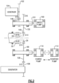
- FIG. 1 shows an integrated drive generator 20. As shown, housing portions 18 and 19 surround the integrated drive generator and a seal plate 17 sits between the housing portions 18 and 19.
- a gas turbine engine 22 may drive an input shaft 23 which selectively drives a disconnect assembly 26.
- the disconnect assembly 26 in turn, drives a carrier shaft 28, which drives a carrier in a gear differential 30.
- Gears 38 have a gear interface 42 with a first ring gear portion 40.
- Gears 36 have a gear interface 48 with a second ring gear portion 46.
- Ring gear portion 40 has a gear interface 50 with a main generator drive gear 52.
- drive gear 52 When drive gear 52 is driven to rotate, it rotates a rotor 56 associated with a stator 58 of the main generator as well as an exciter rotor 60. Electric power is generated for a use 62, as known.
- the frequency of the generated electric power be at a desired frequency.
- a gear 15 that is part of the carrier has a gear interface 16 with a gear 13 driving a shaft 14 also within the speed trimmer.
- the speed trimmer 66 includes a variable unit 72 and a fixed unit 76.
- the units 72 and 76 may each be provided with a plurality of pistons and a swash plate arrangement. If the input speed of the gear 13 is too high, the speed of the gear 52 will also be too high, and hence, the speed trimmer 66 acts to lower the speed of the trim gear 46 which will drop the speed of gear 52. On the other hand, if the input speed is too low, the speed trimmer will increase the trim gear speed and he speed seen by gear 52 will increase.
- variable unit 72 receives an input through gear 13 that is proportional to the speed of the input shaft 23.
- the variable unit 72 also receives a control input from a control monitoring the speed of the generator rotor 56.
- the position of the swash plate in the variable unit 72 is changed to in turn change the speed and direction of the fixed unit 76.
- the fixed unit 76 can change the speed, and direction of rotation of the shaft 70, and this then provides control back through the trim ring gear 46 to change the speed reaching the generator.
- the speed trimmer 66 results in the frequency generated by the generator being closer to constant, and at the desired frequency.
- a permanent magnet generator 32 rotates with the ring gear 40.
- An accessory drive shaft 29 rotates with the ring gear 40 and drives a plurality of accessory gears 31.
- the operation of the integrated drive generator 20 is generally as known in the art. A worker of ordinary skill would recognize that the desired frequency and speed at use 62 would dictate a number of design functions.
- FIG 2 shows the accessory drive gear 29.
- the accessory drive gear 29 drives driven gear 99 and a governor and inversion pump drive gear 130. These driven gears were shown schematically as gear 31 in Figure 1 .
- Gear 130 drives a governor 104 and an inversion pump 100.
- the second gear 99 drives a deaerator through gear 108, as well as a charge pump 110 and a scavenge pump 112.
- the governor and inversion pump drive gear (hereinafter “drive gear 130”) has an outer input gear 140 that is driven by the accessory drive gear 29.
- a drive gear portion 146 in turn drives a gear 102 to drive the governor.
- a shaft 101 is driven by spline teeth on the drive gear 130 to drive the inversion pump 100.
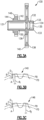
- FIG. 3A shows that drive gear 130 has a gear body 150 that extends from a rear or first end 131 to a forward or second end 133.
- a boss 132 is formed adjacent the forward end 133 and includes an internal bore 135 with eight spline teeth 134. Spline teeth 134 engage drive shaft 101 to drive inversion pump 100.
- a forward, or enlarged, disc 136 extends to an outer diameter 138 and has a plurality of outer input gear teeth 140.
- a shaft portion 142 extends to a flange 144, which has outer drive gear teeth 146.
- Figure 3B shows a gear tooth profile for the gear teeth 140.
- Gear teeth 140 include 62 gear teeth.
- a pitch diameter PD is 7.874 centimeters (3.10 inches). This and all other dimensions are taken with a tolerance range of +/- 0.025 centimeters (0.010 inch).
- a maximum form diameter FD is 7.62 centimeters (3.00 inches).
- the diameter to the outer diameter of the gear teeth 140 is 8.128 centimeters (3.20 inches).
- Gear teeth profiles are defined by roll angles at points A-D, as is known. Notably, the specific roll angles of this gear are not known, however, the nomenclature and technique for identifying the locations is known. Generally, the roll angle at A is at the maximum form diameter FD.
- the roll angle at B is 20 percent away from point A and toward point D.
- the roll angle at C is 80 percent away from point A and toward point D.
- the roll angle at D is at the outer diameter of the gear tooth.
- the roll angle at A for the input gear teeth 140 is 21.6 degrees and in embodiments between 20.9 and 22.3 degrees.
- the roll angle at B is 23.4 degrees and in embodiments between 22.7 and 24.2 degrees.
- the roll angle at C for the outer gear teeth 140 is 29.0 degrees and in embodiments between 28.2 and 29.7 degrees.
- the roll angle at D is 30.8 degrees and in embodiments between 30.0 and 31.5 degrees.
- the diameter d 2 at the outer diameter of the gear teeth 140 is 8.128 centimeters (3.20 inches).
- Figure 3C shows the gear teeth profile for the drive gear teeth 146. There are 29 of teeth 146.
- the pitch diameter PD is 3.683 centimeters (1.45 inches).
- the maximum form diameter FD is 3.454 centimeters (1.36 inches).
- the diameter d to the outer diameter of the gear teeth 146 is 3.937 centimeters (1.55 inches).
- the roll angle at A is 15.6 degrees and in embodiments between 14.7 and 16.2 degrees.
- the roll angle at B is 19.5 degrees and in embodiments between 18.7 and 20.2 degrees.
- the roll angle at C is 31.1 degrees and in embodiments between 30.3 and 31.8 degrees.
- the roll angle at D is 35.0 degrees and in embodiments between 34.2 and 35.7 degrees.
- a method of replacing a governor and inversion pump drive gear includes the steps of removing an existing governor and inversion pump drive gear from an integrated drive generator.
- the integrated drive generator has an input shaft, a gear differential including a carrier shaft and a ring gear for driving a generator and accessory drive gear.
- the accessory drive gear is connected to drive a governor and inversion pump drive gear.
- the method further includes the step of replacing the existing governor and inversion pump drive gear with a replacement governor and inversion pump drive gear including a gear body extending between a first end and a second end and having a disc extending radially outwardly, and a boss extending from the disc toward the second end. Input gear teeth are formed outwardly of an outer diameter of the disc.
- the input gear teeth have a gear tooth profile with roll angles at A, B, C, and D, and the input gear tooth profile having a roll angle at point A between 20.9 and 22.3 degrees, a roll angle at point B between 22.7 and 24.2 degrees, a roll angle at point C between 28.2 and 29.7 degrees, and a roll angle at point D between 30.0 and 31.5 degrees.
- Drive gear teeth are formed on a flange and have a gear tooth profile defined by roll angles at points A, B, C and D, with a drive gear tooth profile at point A having a roll angle of between 14.7 and 16.2 degrees, a roll angle at point B of between 18.7 and 20.2 degrees, a roll angle at point C of between 30.3 and 31.8 degrees, and a roll angle at point D of between 34.2 and 35.7 degrees.
Landscapes
- Engineering & Computer Science (AREA)
- General Engineering & Computer Science (AREA)
- Mechanical Engineering (AREA)
- Chemical & Material Sciences (AREA)
- Combustion & Propulsion (AREA)
- Physics & Mathematics (AREA)
- Fluid Mechanics (AREA)
- General Physics & Mathematics (AREA)
- Automation & Control Theory (AREA)
- Aviation & Aerospace Engineering (AREA)
- Rotary Pumps (AREA)
- Retarders (AREA)
Claims (1)
- Verfahren zum Ersetzen eines Regler- und Inversionspumpenantriebzahnrads, das die folgenden Schritte umfasst:Entfernen eines vorhandenen Regler- und Inversionspumpenantriebzahnrads von einem integrierten Antriebsgenerator, der eine Eingangswelle, ein Getriebedifferential, das eine Trägerwelle enthält, und das Getriebedifferential, das ein Ringzahnrad zum Antreiben eines Generators enthält, aufweist, wobei das Ringzahnrad auch zum Antreiben eines Hilfsantriebszahnrads verbunden ist, wobei das Hilfsantriebszahnrad verbunden ist, um das vorhandene Regler- und Inversionspumpenantriebzahnrad anzutreiben; undErsetzen des vorhandenen Regler- und Inversionspumpenantriebzahnrads durch ein Ersatzregler- und Inversionspumpenantriebzahnrad, das einen Zahnradkörper beinhaltet, der sich zwischen einem ersten Ende und einem zweiten Ende erstreckt und eine Scheibe aufweist, die sich radial nach außen erstreckt, und eine Nabe, die sich von der Scheibe in Richtung des zweiten Endes erstreckt, und Kerbverzahnungen in einer Innenbohrung aufweist, und eine Welle, die sich von der Scheibe in Richtung des zweiten Endes erstreckt, einen Flansch auf der Welle und eine Antriebszahnradverzahnung, die auf dem Flansch ausgebildet ist, wobei es eine Eingangszahnradverzahnung außerhalb eines Außendurchmessers der Scheibe gibt, wobei die Eingangszahnradverzahnung ein Zahnradzahnprofil mit Rollwinkeln an den Punkten A, B, C und D aufweist, wobei der Rollwinkel an Punkt A bei einem maximalen Formdurchmesser liegt, der Rollwinkel an Punkt B 20 Prozent von Punkt A weg und zu Punkt D hin beträgt, der Rollwinkel an Punkt C 80 Prozent von Punkt A weg und zu Punkt D hin beträgt und der Rollwinkel an Punkt D bei dem Außendurchmesser des Zahnradzahns liegt, und das Antriebszahnradprofil einen Rollwinkel an Punkt A zwischen 20,9 und 22,3 Grad, einen Rollwinkel an Punkt B zwischen 22,7 und 24,2 Grad, einen Rollwinkel an Punkt C zwischen 28,2 und 29,7 Grad und ein Rollwinkel an Punkt D zwischen 30,0 und 31,5 Grad aufweist, und die Antriebszahnradverzahnungen ein Zahnradzahnprofil aufweisen, das durch Rollwinkel an den Punkten A, B, C und D definiert ist, wobei ein Antriebszahnradzahnprofil an Punkt A einen Rollwinkel von zwischen 14,7 und 16,2 Grad, einen Rollwinkel an Punkt B von zwischen 18,7 und 20,2 Grad, einen Rollwinkel an Punkt C von zwischen 30,3 und 31,8 Grad und einen Rollwinkel an Punkt D von zwischen 34,2 und 35,7 Grad aufweist;wobei 62 der Eingangszahnradverzahnungen vorhanden sind;wobei die Eingangszahnradverzahnungen einen Teildurchmesser von 3,683 Zentimetern (1,45 Zoll) +/- ,025 Zentimetern (,01 Zoll) aufweisen;wobei die Eingangszahnradverzahnungen einen Außendurchmesser von 8,128 Zentimetern (3,20 Zoll) +/- ,025 Zentimetern (,01 Zoll) aufweisen;wobei die Eingangszahnradverzahnungen einen Außendurchmesser von 8,128 Zentimetern (3,20 Zoll) +/- ,025 Zentimetern (,01 Zoll) aufweisen; undwobei die Ausgangszahnradverzahnungen einen Teildurchmesser von 3,683 Zentimetern (1,45 Zoll) +/- ,025 Zentimetern (,01 Zoll) aufweisen;wobei der Rollwinkel an Punkt A 15,6 Grad beträgt, der Rollwinkel an Punkt B 19,5 Grad beträgt, der Rollwinkel an Punkt C 31,1 Grad beträgt und der Rollwinkel an Punkt D 35,0 Grad beträgt.
Applications Claiming Priority (1)
| Application Number | Priority Date | Filing Date | Title |
|---|---|---|---|
| US15/813,300 US10599165B2 (en) | 2017-11-15 | 2017-11-15 | Governor and inversion pump drive gear |
Publications (2)
| Publication Number | Publication Date |
|---|---|
| EP3486528A1 EP3486528A1 (de) | 2019-05-22 |
| EP3486528B1 true EP3486528B1 (de) | 2024-07-24 |
Family
ID=64270745
Family Applications (1)
| Application Number | Title | Priority Date | Filing Date |
|---|---|---|---|
| EP18205497.3A Active EP3486528B1 (de) | 2017-11-15 | 2018-11-09 | Regler- und inversionspumpenantriebzahnrad |
Country Status (2)
| Country | Link |
|---|---|
| US (1) | US10599165B2 (de) |
| EP (1) | EP3486528B1 (de) |
Families Citing this family (2)
| Publication number | Priority date | Publication date | Assignee | Title |
|---|---|---|---|---|
| US10760665B2 (en) * | 2018-01-04 | 2020-09-01 | Hamilton Sundstrand Corporation | Governor drive gear for integrated drive generator |
| FR3118483B1 (fr) | 2020-12-28 | 2024-02-16 | Safran Aircraft Engines | Module de turbomachine equipe d’une machine electrique et turbomachine equipee d’un tel module |
Family Cites Families (10)
| Publication number | Priority date | Publication date | Assignee | Title |
|---|---|---|---|---|
| US4640149A (en) * | 1983-03-04 | 1987-02-03 | The Boeing Company | High profile contact ratio, non-involute gear tooth form and method |
| US5083474A (en) * | 1991-06-04 | 1992-01-28 | Axicon Gear Company | Zero transmission error gearing |
| US5271288A (en) * | 1992-03-09 | 1993-12-21 | United Technologies Corporation | Helicopter noise reduction through gearing modifications |
| US5341699A (en) * | 1993-04-06 | 1994-08-30 | Axicon Gear Company | Zero dynamic increment gearing |
| US5485761A (en) * | 1993-04-06 | 1996-01-23 | Axicon Gear Company | Articulated differential crowning |
| SE519200C2 (sv) | 2001-06-05 | 2003-01-28 | Volvo Aero Corp | Gasturbinanordning med ett arrangemang för drivning av en eller flera hjälpapparater |
| US8132480B2 (en) * | 2009-05-06 | 2012-03-13 | Hamilton Sundstrand Corporation | Pump gear and pump assembly for a generator |
| US8051738B2 (en) * | 2009-05-06 | 2011-11-08 | Hamilton Sundstrand Corporation | Rotor gear for a generator |
| US7926381B2 (en) | 2009-06-30 | 2011-04-19 | Hamilton Sundstrand Corporation | Idler gear for a generator |
| US9494225B2 (en) * | 2014-02-17 | 2016-11-15 | Hamilton Sundstrand Corporation | Electric generator oil pump driven gear |
-
2017
- 2017-11-15 US US15/813,300 patent/US10599165B2/en active Active
-
2018
- 2018-11-09 EP EP18205497.3A patent/EP3486528B1/de active Active
Also Published As
| Publication number | Publication date |
|---|---|
| US20190146526A1 (en) | 2019-05-16 |
| US10599165B2 (en) | 2020-03-24 |
| EP3486528A1 (de) | 2019-05-22 |
Similar Documents
| Publication | Publication Date | Title |
|---|---|---|
| EP3486528B1 (de) | Regler- und inversionspumpenantriebzahnrad | |
| EP3508746B1 (de) | Eingangswelle zur verwendung in einem integrierten antriebsgetriebe | |
| EP3467350A1 (de) | Trimmzahnkranz für integrierten antriebsgenerator | |
| EP3514398B1 (de) | Innerer lagerring einer festen blockwelle für einen integrierten antriebsgenerator | |
| EP3467331B1 (de) | Trennwelle für einen integrierten antriebsgenerator | |
| EP3509199B1 (de) | Hauptgeneratorstatorhülse für integrierten antriebsgenerator | |
| EP3467349B1 (de) | Hilfsantriebsgetriebe für integrierten antriebsgenerator | |
| EP3486529B1 (de) | Antriebszahnrad einer rückförder-/ladepumpe für integrierten antriebsgenerator | |
| EP3511594B1 (de) | Feste blockwelle für einen integrierten antriebsgenerator | |
| EP3508757B1 (de) | Integrierter antriebsgenerator und entsprechendes verfahren zum ersetzen eines reglergetriebes in einem solchen generator | |
| EP3502514B1 (de) | Abgangszahnkranz für integrierten antriebsgenerator | |
| EP3508758B1 (de) | Angetriebenes zahnrad für generator eines integrierten antriebsgenerator | |
| EP3511595B1 (de) | Variable blockwelle für einen integrierten antriebsgenerator | |
| EP3489532B1 (de) | Verschleissring für einen integrierten antriebsgenerator | |
| EP3490111A1 (de) | Permanentmagnetgeneratorrotor für einen integrierten antriebsgenerator |
Legal Events
| Date | Code | Title | Description |
|---|---|---|---|
| PUAI | Public reference made under article 153(3) epc to a published international application that has entered the european phase |
Free format text: ORIGINAL CODE: 0009012 |
|
| STAA | Information on the status of an ep patent application or granted ep patent |
Free format text: STATUS: THE APPLICATION HAS BEEN PUBLISHED |
|
| AK | Designated contracting states |
Kind code of ref document: A1 Designated state(s): AL AT BE BG CH CY CZ DE DK EE ES FI FR GB GR HR HU IE IS IT LI LT LU LV MC MK MT NL NO PL PT RO RS SE SI SK SM TR |
|
| AX | Request for extension of the european patent |
Extension state: BA ME |
|
| STAA | Information on the status of an ep patent application or granted ep patent |
Free format text: STATUS: REQUEST FOR EXAMINATION WAS MADE |
|
| 17P | Request for examination filed |
Effective date: 20191121 |
|
| RBV | Designated contracting states (corrected) |
Designated state(s): AL AT BE BG CH CY CZ DE DK EE ES FI FR GB GR HR HU IE IS IT LI LT LU LV MC MK MT NL NO PL PT RO RS SE SI SK SM TR |
|
| STAA | Information on the status of an ep patent application or granted ep patent |
Free format text: STATUS: EXAMINATION IS IN PROGRESS |
|
| 17Q | First examination report despatched |
Effective date: 20201008 |
|
| GRAP | Despatch of communication of intention to grant a patent |
Free format text: ORIGINAL CODE: EPIDOSNIGR1 |
|
| STAA | Information on the status of an ep patent application or granted ep patent |
Free format text: STATUS: GRANT OF PATENT IS INTENDED |
|
| INTG | Intention to grant announced |
Effective date: 20240301 |
|
| GRAS | Grant fee paid |
Free format text: ORIGINAL CODE: EPIDOSNIGR3 |
|
| GRAA | (expected) grant |
Free format text: ORIGINAL CODE: 0009210 |
|
| STAA | Information on the status of an ep patent application or granted ep patent |
Free format text: STATUS: THE PATENT HAS BEEN GRANTED |
|
| AK | Designated contracting states |
Kind code of ref document: B1 Designated state(s): AL AT BE BG CH CY CZ DE DK EE ES FI FR GB GR HR HU IE IS IT LI LT LU LV MC MK MT NL NO PL PT RO RS SE SI SK SM TR |
|
| REG | Reference to a national code |
Ref country code: GB Ref legal event code: FG4D |
|
| REG | Reference to a national code |
Ref country code: CH Ref legal event code: EP |
|
| REG | Reference to a national code |
Ref country code: DE Ref legal event code: R096 Ref document number: 602018072112 Country of ref document: DE |
|
| REG | Reference to a national code |
Ref country code: IE Ref legal event code: FG4D |
|
| REG | Reference to a national code |
Ref country code: LT Ref legal event code: MG9D |
|
| REG | Reference to a national code |
Ref country code: NL Ref legal event code: MP Effective date: 20240724 |
|
| PG25 | Lapsed in a contracting state [announced via postgrant information from national office to epo] |
Ref country code: PT Free format text: LAPSE BECAUSE OF FAILURE TO SUBMIT A TRANSLATION OF THE DESCRIPTION OR TO PAY THE FEE WITHIN THE PRESCRIBED TIME-LIMIT Effective date: 20241125 |
|
| REG | Reference to a national code |
Ref country code: AT Ref legal event code: MK05 Ref document number: 1706552 Country of ref document: AT Kind code of ref document: T Effective date: 20240724 |
|
| PG25 | Lapsed in a contracting state [announced via postgrant information from national office to epo] |
Ref country code: NL Free format text: LAPSE BECAUSE OF FAILURE TO SUBMIT A TRANSLATION OF THE DESCRIPTION OR TO PAY THE FEE WITHIN THE PRESCRIBED TIME-LIMIT Effective date: 20240724 |
|
| PG25 | Lapsed in a contracting state [announced via postgrant information from national office to epo] |
Ref country code: PT Free format text: LAPSE BECAUSE OF FAILURE TO SUBMIT A TRANSLATION OF THE DESCRIPTION OR TO PAY THE FEE WITHIN THE PRESCRIBED TIME-LIMIT Effective date: 20241125 Ref country code: NL Free format text: LAPSE BECAUSE OF FAILURE TO SUBMIT A TRANSLATION OF THE DESCRIPTION OR TO PAY THE FEE WITHIN THE PRESCRIBED TIME-LIMIT Effective date: 20240724 |
|
| PG25 | Lapsed in a contracting state [announced via postgrant information from national office to epo] |
Ref country code: NO Free format text: LAPSE BECAUSE OF FAILURE TO SUBMIT A TRANSLATION OF THE DESCRIPTION OR TO PAY THE FEE WITHIN THE PRESCRIBED TIME-LIMIT Effective date: 20241024 |
|
| PG25 | Lapsed in a contracting state [announced via postgrant information from national office to epo] |
Ref country code: FI Free format text: LAPSE BECAUSE OF FAILURE TO SUBMIT A TRANSLATION OF THE DESCRIPTION OR TO PAY THE FEE WITHIN THE PRESCRIBED TIME-LIMIT Effective date: 20240724 Ref country code: GR Free format text: LAPSE BECAUSE OF FAILURE TO SUBMIT A TRANSLATION OF THE DESCRIPTION OR TO PAY THE FEE WITHIN THE PRESCRIBED TIME-LIMIT Effective date: 20241025 Ref country code: PL Free format text: LAPSE BECAUSE OF FAILURE TO SUBMIT A TRANSLATION OF THE DESCRIPTION OR TO PAY THE FEE WITHIN THE PRESCRIBED TIME-LIMIT Effective date: 20240724 |
|
| PG25 | Lapsed in a contracting state [announced via postgrant information from national office to epo] |
Ref country code: BG Free format text: LAPSE BECAUSE OF FAILURE TO SUBMIT A TRANSLATION OF THE DESCRIPTION OR TO PAY THE FEE WITHIN THE PRESCRIBED TIME-LIMIT Effective date: 20240724 |
|
| PG25 | Lapsed in a contracting state [announced via postgrant information from national office to epo] |
Ref country code: LV Free format text: LAPSE BECAUSE OF FAILURE TO SUBMIT A TRANSLATION OF THE DESCRIPTION OR TO PAY THE FEE WITHIN THE PRESCRIBED TIME-LIMIT Effective date: 20240724 |
|
| PG25 | Lapsed in a contracting state [announced via postgrant information from national office to epo] |
Ref country code: IS Free format text: LAPSE BECAUSE OF FAILURE TO SUBMIT A TRANSLATION OF THE DESCRIPTION OR TO PAY THE FEE WITHIN THE PRESCRIBED TIME-LIMIT Effective date: 20241124 Ref country code: AT Free format text: LAPSE BECAUSE OF FAILURE TO SUBMIT A TRANSLATION OF THE DESCRIPTION OR TO PAY THE FEE WITHIN THE PRESCRIBED TIME-LIMIT Effective date: 20240724 |
|
| PG25 | Lapsed in a contracting state [announced via postgrant information from national office to epo] |
Ref country code: HR Free format text: LAPSE BECAUSE OF FAILURE TO SUBMIT A TRANSLATION OF THE DESCRIPTION OR TO PAY THE FEE WITHIN THE PRESCRIBED TIME-LIMIT Effective date: 20240724 |
|
| PG25 | Lapsed in a contracting state [announced via postgrant information from national office to epo] |
Ref country code: ES Free format text: LAPSE BECAUSE OF FAILURE TO SUBMIT A TRANSLATION OF THE DESCRIPTION OR TO PAY THE FEE WITHIN THE PRESCRIBED TIME-LIMIT Effective date: 20240724 Ref country code: RS Free format text: LAPSE BECAUSE OF FAILURE TO SUBMIT A TRANSLATION OF THE DESCRIPTION OR TO PAY THE FEE WITHIN THE PRESCRIBED TIME-LIMIT Effective date: 20241024 |
|
| PG25 | Lapsed in a contracting state [announced via postgrant information from national office to epo] |
Ref country code: RS Free format text: LAPSE BECAUSE OF FAILURE TO SUBMIT A TRANSLATION OF THE DESCRIPTION OR TO PAY THE FEE WITHIN THE PRESCRIBED TIME-LIMIT Effective date: 20241024 Ref country code: PL Free format text: LAPSE BECAUSE OF FAILURE TO SUBMIT A TRANSLATION OF THE DESCRIPTION OR TO PAY THE FEE WITHIN THE PRESCRIBED TIME-LIMIT Effective date: 20240724 Ref country code: NO Free format text: LAPSE BECAUSE OF FAILURE TO SUBMIT A TRANSLATION OF THE DESCRIPTION OR TO PAY THE FEE WITHIN THE PRESCRIBED TIME-LIMIT Effective date: 20241024 Ref country code: LV Free format text: LAPSE BECAUSE OF FAILURE TO SUBMIT A TRANSLATION OF THE DESCRIPTION OR TO PAY THE FEE WITHIN THE PRESCRIBED TIME-LIMIT Effective date: 20240724 Ref country code: IS Free format text: LAPSE BECAUSE OF FAILURE TO SUBMIT A TRANSLATION OF THE DESCRIPTION OR TO PAY THE FEE WITHIN THE PRESCRIBED TIME-LIMIT Effective date: 20241124 Ref country code: HR Free format text: LAPSE BECAUSE OF FAILURE TO SUBMIT A TRANSLATION OF THE DESCRIPTION OR TO PAY THE FEE WITHIN THE PRESCRIBED TIME-LIMIT Effective date: 20240724 Ref country code: GR Free format text: LAPSE BECAUSE OF FAILURE TO SUBMIT A TRANSLATION OF THE DESCRIPTION OR TO PAY THE FEE WITHIN THE PRESCRIBED TIME-LIMIT Effective date: 20241025 Ref country code: FI Free format text: LAPSE BECAUSE OF FAILURE TO SUBMIT A TRANSLATION OF THE DESCRIPTION OR TO PAY THE FEE WITHIN THE PRESCRIBED TIME-LIMIT Effective date: 20240724 Ref country code: ES Free format text: LAPSE BECAUSE OF FAILURE TO SUBMIT A TRANSLATION OF THE DESCRIPTION OR TO PAY THE FEE WITHIN THE PRESCRIBED TIME-LIMIT Effective date: 20240724 Ref country code: BG Free format text: LAPSE BECAUSE OF FAILURE TO SUBMIT A TRANSLATION OF THE DESCRIPTION OR TO PAY THE FEE WITHIN THE PRESCRIBED TIME-LIMIT Effective date: 20240724 Ref country code: AT Free format text: LAPSE BECAUSE OF FAILURE TO SUBMIT A TRANSLATION OF THE DESCRIPTION OR TO PAY THE FEE WITHIN THE PRESCRIBED TIME-LIMIT Effective date: 20240724 |
|
| PG25 | Lapsed in a contracting state [announced via postgrant information from national office to epo] |
Ref country code: RO Free format text: LAPSE BECAUSE OF FAILURE TO SUBMIT A TRANSLATION OF THE DESCRIPTION OR TO PAY THE FEE WITHIN THE PRESCRIBED TIME-LIMIT Effective date: 20240724 Ref country code: DK Free format text: LAPSE BECAUSE OF FAILURE TO SUBMIT A TRANSLATION OF THE DESCRIPTION OR TO PAY THE FEE WITHIN THE PRESCRIBED TIME-LIMIT Effective date: 20240724 Ref country code: SM Free format text: LAPSE BECAUSE OF FAILURE TO SUBMIT A TRANSLATION OF THE DESCRIPTION OR TO PAY THE FEE WITHIN THE PRESCRIBED TIME-LIMIT Effective date: 20240724 |
|
| PG25 | Lapsed in a contracting state [announced via postgrant information from national office to epo] |
Ref country code: EE Free format text: LAPSE BECAUSE OF FAILURE TO SUBMIT A TRANSLATION OF THE DESCRIPTION OR TO PAY THE FEE WITHIN THE PRESCRIBED TIME-LIMIT Effective date: 20240724 |
|
| PG25 | Lapsed in a contracting state [announced via postgrant information from national office to epo] |
Ref country code: CZ Free format text: LAPSE BECAUSE OF FAILURE TO SUBMIT A TRANSLATION OF THE DESCRIPTION OR TO PAY THE FEE WITHIN THE PRESCRIBED TIME-LIMIT Effective date: 20240724 |
|
| REG | Reference to a national code |
Ref country code: DE Ref legal event code: R097 Ref document number: 602018072112 Country of ref document: DE |
|
| PG25 | Lapsed in a contracting state [announced via postgrant information from national office to epo] |
Ref country code: IT Free format text: LAPSE BECAUSE OF FAILURE TO SUBMIT A TRANSLATION OF THE DESCRIPTION OR TO PAY THE FEE WITHIN THE PRESCRIBED TIME-LIMIT Effective date: 20240724 Ref country code: SK Free format text: LAPSE BECAUSE OF FAILURE TO SUBMIT A TRANSLATION OF THE DESCRIPTION OR TO PAY THE FEE WITHIN THE PRESCRIBED TIME-LIMIT Effective date: 20240724 |
|
| PLBE | No opposition filed within time limit |
Free format text: ORIGINAL CODE: 0009261 |
|
| STAA | Information on the status of an ep patent application or granted ep patent |
Free format text: STATUS: NO OPPOSITION FILED WITHIN TIME LIMIT |
|
| REG | Reference to a national code |
Ref country code: CH Ref legal event code: PL |
|
| 26N | No opposition filed |
Effective date: 20250425 |
|
| PG25 | Lapsed in a contracting state [announced via postgrant information from national office to epo] |
Ref country code: MC Free format text: LAPSE BECAUSE OF FAILURE TO SUBMIT A TRANSLATION OF THE DESCRIPTION OR TO PAY THE FEE WITHIN THE PRESCRIBED TIME-LIMIT Effective date: 20240724 |
|
| PG25 | Lapsed in a contracting state [announced via postgrant information from national office to epo] |
Ref country code: LU Free format text: LAPSE BECAUSE OF NON-PAYMENT OF DUE FEES Effective date: 20241109 |
|
| REG | Reference to a national code |
Ref country code: CH Ref legal event code: PL |
|
| PG25 | Lapsed in a contracting state [announced via postgrant information from national office to epo] |
Ref country code: CH Free format text: LAPSE BECAUSE OF NON-PAYMENT OF DUE FEES Effective date: 20241130 |
|
| REG | Reference to a national code |
Ref country code: BE Ref legal event code: MM Effective date: 20241130 |
|
| PG25 | Lapsed in a contracting state [announced via postgrant information from national office to epo] |
Ref country code: SE Free format text: LAPSE BECAUSE OF FAILURE TO SUBMIT A TRANSLATION OF THE DESCRIPTION OR TO PAY THE FEE WITHIN THE PRESCRIBED TIME-LIMIT Effective date: 20240724 |
|
| PG25 | Lapsed in a contracting state [announced via postgrant information from national office to epo] |
Ref country code: BE Free format text: LAPSE BECAUSE OF NON-PAYMENT OF DUE FEES Effective date: 20241130 |
|
| PG25 | Lapsed in a contracting state [announced via postgrant information from national office to epo] |
Ref country code: IE Free format text: LAPSE BECAUSE OF NON-PAYMENT OF DUE FEES Effective date: 20241109 |
|
| PGFP | Annual fee paid to national office [announced via postgrant information from national office to epo] |
Ref country code: DE Payment date: 20251022 Year of fee payment: 8 |
|
| PGFP | Annual fee paid to national office [announced via postgrant information from national office to epo] |
Ref country code: GB Payment date: 20251022 Year of fee payment: 8 |
|
| PGFP | Annual fee paid to national office [announced via postgrant information from national office to epo] |
Ref country code: FR Payment date: 20251023 Year of fee payment: 8 |
|
| PG25 | Lapsed in a contracting state [announced via postgrant information from national office to epo] |
Ref country code: HU Free format text: LAPSE BECAUSE OF FAILURE TO SUBMIT A TRANSLATION OF THE DESCRIPTION OR TO PAY THE FEE WITHIN THE PRESCRIBED TIME-LIMIT; INVALID AB INITIO Effective date: 20181109 |
|
| PG25 | Lapsed in a contracting state [announced via postgrant information from national office to epo] |
Ref country code: CY Free format text: LAPSE BECAUSE OF FAILURE TO SUBMIT A TRANSLATION OF THE DESCRIPTION OR TO PAY THE FEE WITHIN THE PRESCRIBED TIME-LIMIT; INVALID AB INITIO Effective date: 20181109 |