EP3486539A1 - Rohrleitungselement für flüssigkeitsleitungen - Google Patents
Rohrleitungselement für flüssigkeitsleitungen Download PDFInfo
- Publication number
- EP3486539A1 EP3486539A1 EP18206834.6A EP18206834A EP3486539A1 EP 3486539 A1 EP3486539 A1 EP 3486539A1 EP 18206834 A EP18206834 A EP 18206834A EP 3486539 A1 EP3486539 A1 EP 3486539A1
- Authority
- EP
- European Patent Office
- Prior art keywords
- outer tube
- pipe element
- inner body
- connecting portion
- region
- Prior art date
- Legal status (The legal status is an assumption and is not a legal conclusion. Google has not performed a legal analysis and makes no representation as to the accuracy of the status listed.)
- Granted
Links
Images


Classifications
-
- F—MECHANICAL ENGINEERING; LIGHTING; HEATING; WEAPONS; BLASTING
- F16—ENGINEERING ELEMENTS AND UNITS; GENERAL MEASURES FOR PRODUCING AND MAINTAINING EFFECTIVE FUNCTIONING OF MACHINES OR INSTALLATIONS; THERMAL INSULATION IN GENERAL
- F16L—PIPES; JOINTS OR FITTINGS FOR PIPES; SUPPORTS FOR PIPES, CABLES OR PROTECTIVE TUBING; MEANS FOR THERMAL INSULATION IN GENERAL
- F16L9/00—Rigid pipes
- F16L9/18—Double-walled pipes; Multi-channel pipes or pipe assemblies
Definitions
- Pipe elements of the type mentioned are used, for example, in the automotive field to connect a fuel accumulator with a feed unit, wherein the feed unit is adapted to supply the combustion chambers of a motor vehicle engine with fuel.
- the pipe element as part of a fluid line then offers, for example, the possibility of arranging a feeding hose and is also designed for connection to the feed unit.
- the pipe element can also be used in any other liquid-carrying systems as part of the liquid line.
- both the flow behavior and the volume flow through the inner cross section of the outer tube is determined.
- the resulting through the inner cross-section volume determines in the case of using the piping element for supplying fuel in the motor vehicle also how much fuel after a shutdown in the combustion chambers upstream system remains. When the vehicle is restarted, this remaining fuel is additionally consumed.
- the invention has for its object to provide a pipe element which on the one hand has a sufficiently large volume to provide a sufficiently large volume flow, but on the other hand offers the possibility to remove in a simple manner in case of need liquid energy saving from the pipe element, for example to suck off a pump.
- the pipe element according to the invention has an outer tube which has a connecting portion and a buffer portion.
- the connecting portion of the outer tube extends in the longitudinal axis direction of the outer tube and denotes the portion of the outer tube over which an inner body arranged in the outer tube also extends in the longitudinal axis direction of the outer tube.
- the buffer section adjoins the connecting section in the longitudinal axis direction, which is the section of the outer tube which, viewed in the longitudinal axis direction of the outer tube, is not covered by the inner body. This is achieved in that the inner body is shorter than the outer tube.
- the inner body determines the flow channel along the connecting portion, wherein viewed through the inner body, the cross section of the flow channel - viewed perpendicular to the longitudinal axis - in the region of the connecting portion is smaller than the corresponding cross section in the region of the buffer section, the connects the end face of the inner body.
- the inventive design of the pipe element causes a reduction of the provided by the outer tube inner volume of the pipe element Insertion of the inner body in the outer tube, wherein at the same time by maintaining the inner cross section of the outer tube in the region of the buffer portion, a sufficiently large storage space is created, which is suitable for providing a required amount of liquid, for example. Amount of fuel.
- the use of an inner body for reducing the flow channel in the region of the connecting portion is characterized in that it allows a determination of the flow channel within the outer tube in a simple manner, whereby the production can be realized particularly cost-effective by a simple introduction of the inner body in the outer tube.
- the configuration of the interior of the outer tube in the region of the buffer section is basically freely selectable. According to a particularly advantageous embodiment of the invention it is provided that the buffer section has a limited by the inner diameter of the outer tube buffer chamber. According to this embodiment of the invention, the buffer chamber connects in the longitudinal axis direction of the outer tube directly to the inner body and is limited in the circumferential direction by the inner wall of the outer tube. The size of the buffer chamber in the longitudinal axis direction of the outer tube is determined over the length of the region of the outer tube projecting beyond the inner body. The design of the buffer chamber according to this embodiment of the invention requires, with the exception of the arrangement of the inner body within the outer tube no further processing.
- the pipe element is basically suitable for being connected as part of a liquid delivery line with other elements of the liquid delivery line.
- the pipe element can be designed with suitable connecting elements which enable a liquid-tight connection with corresponding connection elements.
- the piping element can be used to be connected to a portion of a hose line, for which purpose the hose is guided over the outer tube.
- the pipe element has an outer peripheral bead, wherein the bead particularly preferably by plastic deformation of the outer tube, in particular by upsetting the Outer tube is formed.
- An outer peripheral bead allows a particularly reliable arrangement of a hose member, which can be locked in particular form-locking in the direction of the hose element behind the bead.
- the bead can be formed by applying a material to the outer surface of the outer tube.
- the bead is formed by plastic deformation of the outer tube, in particular by upsetting the outer tube in the longitudinal axis direction, which offers the advantage that can be dispensed with a connection of a separate bead element with the outer tube.
- the upsetting represents a particularly simple and cost-effective production process.
- a possible disadvantage of the compression process which leads to a constriction in the corresponding region on the inside of the outer tube due to the deformation, is also avoided in the pipeline element according to the invention in that in a suitable embodiment of the Inner body, the constriction has no effect on the flow channel when the compression is arranged in the region of the connecting portion of the outer tube.
- the outer tube tapers at one end and / or has a circumferential flange at the other end.
- This embodiment of the invention allows, for example, in the embodiment of a tapered end a simple assembly of a hose member to the pipe element.
- the design of a flange also allows a reliable determination of the pipe element to eg. A supply unit which supplies a motor vehicle engine with fuel.
- the pipe element can in principle have any desired shape and, in its simplest embodiment, is designed as a linear pipe body. According to a particularly advantageous embodiment of the invention, however, it is provided that the pipe element has a bend, wherein particularly preferably the inner body ends in the region of the bend, that the buffer chamber has a wedge-shaped shape.
- the inner body is deformed together with the outer tube by a bending process.
- the inner body supports the outer tube, so that, in the case of a dimensioning of the outer tube that takes into account the bending process, material savings can be made with respect to those outer tubes to be bent, which have no inner body.
- a wedge-shaped buffer chamber is formed, which represents a sufficiently large storage space in a particularly reliable manner, which provides a sufficiently large volume in the flow direction in case of need.
- the configuration of the inner body can basically be done in any way. It is conceivable, for example, the use of a solid body with grooves extending on the outside in the longitudinal axis direction, which form the flow channels with the inner surface of the outer tube in the mounted state in which the inner body rests against the inner surface of the outer tube.
- the inner body is formed by a voltage applied to the inside of the outer tube inner tube.
- This embodiment of the invention allows a particularly simple and cost-effective production of a pipe element according to the invention, wherein over the inner cross section of the inner tube, the cross section of the flow channel can be determined particularly easily.
- the use of an inner tube has the advantage that, in the case of a preferred bending of the tubular element, it compensates for a stretching-induced material reduction occurring on one side of the bend.
- the bivalve in the region of the connecting pipe element has a high stability.
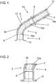
- a pipe element 1a is formed of an outer tube 2 and an inner tube 3a designed as an inner body, wherein the inner tube 3a rests with its outer side 14a on an inner side 13 of the outer tube 2.
- the pipe element 3a forms a connecting portion 4, at which a buffer chamber 6 connects in the longitudinal axis direction in the direction of a flange 11 having end of the outer tube 2, which is arranged in the region of a buffer portion 5 of the outer tube 2 is.
- the outer pipe 2 has a bead 7 formed by swaging and, at its end opposite the flange 11, a taper 10.
- the bead 7 is formed by upsetting.
- a constriction 8 formed on the inside 13 of the outer tube 2 by upsetting the outer tube 2 has no influence on the flow behavior of a liquid flowing through the pipeline element 1a, after the flow channel 12a is determined by the inner cross section of the inner tube 3a.
- the pipe element 1a also has a bend 9, wherein the inner pipe 3a is arranged such that it ends in the region of the bend 9, so that a wedge-shaped buffer chamber 6 is formed, which adjoins directly to an end face 16a of the inner pipe 3a (see. FIGS. 1 and 2 ).
- FIG. 4 A second embodiment of a piping element 1b is shown in FIG FIG. 4 shown.
- piping element 1a is the inner body formed by an inner rod 3b, which has two helically extending on the outside of the inner rod 3b flow channels 12b, which are defined in the mounted position by the inner side 13 of the outer tube 2.
- the inner rod 3b lies with its outer side 14b against the inner side 13 of the outer tube 2.
- a buffer chamber 6 adjoins the end face 16 b of the inner rod 3 b, which is likewise wedge-shaped, after the inner rod 3 b ends in the region of the bend 9.
Landscapes
- Engineering & Computer Science (AREA)
- General Engineering & Computer Science (AREA)
- Mechanical Engineering (AREA)
- Rigid Pipes And Flexible Pipes (AREA)
Abstract
Description
- Die Erfindung betrifft ein Rohrleitungselement für Flüssigkeitsleitungen, mit einem Außenrohr, das
- einen Verbindungsabschnitt und
- einen an den Verbindungsabschnitt angrenzenden Pufferabschnitt
- Rohrleitungselemente der eingangs genannten Art werden bspw. im Kraftfahrzeugbereich dazu verwendet, um einen Kraftstoffspeicher mit einer Zuführeinheit zu verbinden, wobei die Zuführeinheit dazu ausgebildet ist, um die Verbrennungsräume eines Kraftfahrzeugmotors mit Kraftstoff zu versorgen. Das Rohrleitungselement als Bestandteil einer Flüssigkeitsleitung bietet dann bspw. die Möglichkeit zur Anordnung eines zuführenden Schlauchs und ist darüber hinaus zur Verbindung mit der Zuführeinheit ausgebildet. Darüber hinaus kann das Rohrleitungselement jedoch auch in beliebigen anderen flüssigkeitsführenden Systemen als Bestandteil der Flüssigkeitsleitung eingesetzt werden.
- Bei den bekannten Rohrleitungselementen wird sowohl das Strömungsverhalten wie auch der Volumenstrom durch den Innenquerschnitt des Außenrohres festgelegt. Das sich durch den Innenquerschnitt ergebende Volumen bestimmt im Falle der Verwendung des Rohrleitungselements zur Zuführung von Kraftstoff im Kraftfahrzeug auch, wieviel Kraftstoff nach einem Abschaltvorgang in dem den Brennräumen vorgelagerten System verbleibt. Bei einem Neustart des Fahrzeugs wird dieser verbliebene Kraftstoff zusätzlich verbraucht. Insbesondere bei modernen Verbrennungsmotoren mit automatischen Abschalteinrichtungen hat dies zur Folge, dass aufgrund einer Vielzahl von Abschaltvorgängen im täglichen Betrieb eine erhebliche Menge an Kraftstoff ungenutzt verbrannt wird.
- Der Einsatz einer Pumpe zur vorherigen Absaugung des überflüssigen Kraftstoffs führt nicht zum gewünschten Erfolg, nachdem aufgrund des Volumens des Rohrleitungselements die Betriebsdauer einer solchen Pumpe einen derart hohen Energiebedarf aufweisen würde, dass sich die durch die Absaugung ergebende Kraftstoffeinsparung aufgehoben werden würde oder es sogar zu einem erhöhten Kraftstoffverbrauch zum Betrieb der Pumpe kommen würde.
- Hiervon ausgehend liegt der Erfindung die Aufgabe zugrunde, ein Rohrleitungselement bereitzustellen, welches einerseits ein ausreichend großes Volumen aufweist, um einen ausreichend großen Volumenstrom bereitzustellen, andererseits jedoch die Möglichkeit bietet, in einfacher Weise im Bedarfsfall Flüssigkeit energiesparend aus dem Rohrleitungselement zu entfernen, bspw. mit einer Pumpe abzusaugen.
- Die Erfindung löst die Aufgabe durch ein Rohrleitungselement mit den Merkmalen des Anspruchs 1. Vorteilhafte Weiterbildungen der Erfindung sind in den abhängigen Ansprüchen angegeben.
- Das erfindungsgemäße Rohrleitungselement weist ein Außenrohr auf, welches einen Verbindungsabschnitt und einen Pufferabschnitt besitzt. Der Verbindungsabschnitt des Außenrohres erstreckt sich dabei in Längsachsenrichtung des Außenrohres und bezeichnet den Abschnitt des Außenrohres, über den sich ein in dem Außenrohr angeordneter Innenkörper ebenfalls in Längsachsenrichtung des Außenrohres erstreckt. An den Verbindungsabschnitt schließt sich in Längsachsenrichtung der Pufferabschnitt an, bei dem es sich um den Abschnitt des Außenrohres handelt, welcher in Längsachsenrichtung des Außenrohres betrachtet nicht von dem Innenkörper überdeckt ist. Dies wird dadurch erreicht, dass der Innenkörper kürzer ist als das Außenrohr.
- Aufgrund seiner Anordnung des Innenkörpers im Inneren des Außenrohres bestimmt der Innenkörper erfindungsgemäß den Strömungskanal entlang des Verbindungsabschnittes, wobei durch den Innenkörper der Querschnitt des Strömungskanals - senkrecht zur Längsachse betrachtet - im Bereich des Verbindungsabschnitts kleiner ist als der entsprechende Querschnitt im Bereich des Pufferabschnitts, der sich stirnseitig an den Innenkörper anschließt.
- Die erfindungsgemäße Ausgestaltung des Rohrleitungselements bewirkt eine Reduzierung des durch das Außenrohr bereitgestellten Innenvolumens des Rohrleitungselements durch Einbringung des Innenkörpers in das Außenrohr, wobei gleichzeitig durch eine Beibehaltung des Innenquerschnitts des Außenrohres im Bereich des Pufferabschnitts ein ausreichend großer Speicherraum geschaffen wird, welcher zur Vorhaltung einer im Bedarf erforderlichen Flüssigkeitsmenge, bspw. Kraftstoffmenge geeignet ist. Die Verwendung eines Innenkörpers zur Reduzierung des Strömungskanals im Bereich des Verbindungsabschnitts zeichnet sich dabei dadurch aus, dass dieser in einfacher Weise eine Festlegung des Strömungskanals innerhalb des Außenrohres ermöglicht, wobei sich die Herstellung besonders kostengünstig durch eine einfache Einbringung des Innenkörpers in das Außenrohr realisieren lässt.
- Die Ausgestaltung des Innenraums des Außenrohres im Bereich des Pufferabschnitts ist grundsätzlich frei wählbar. Nach einer besonders vorteilhaften Ausgestaltung der Erfindung ist vorgesehen, dass der Pufferabschnitt eine umfangsseitig durch den Innendurchmesser des Außenrohres begrenzte Pufferkammer aufweist. Gemäß dieser Ausgestaltung der Erfindung schließt sich die Pufferkammer in Längsachsenrichtung des Außenrohres direkt an den Innenkörper an und ist in Umfangsrichtung durch die Innenwandung des Außenrohres begrenzt. Über die Länge des über den Innenkörper hinausragenden Bereichs des Außenrohres wird dabei die Größe der Pufferkammer in Längsachsenrichtung des Außenrohres bestimmt. Die Ausgestaltung der Pufferkammer gemäß dieser Weiterbildung der Erfindung erfordert mit Ausnahme der Anordnung des Innenkörpers innerhalb des Außenrohres keine weitere Bearbeitung.
- Das Rohrleitungselement ist grundsätzlich dazu geeignet, um als Bestandteil einer Flüssigkeitsförderleitung mit weiteren Elementen der Flüssigkeitsförderleitung verbunden zu werden. So kann das Rohrleitungselement bspw. mit geeigneten Verbindungselementen ausgestaltet sein, die eine flüssigkeitsdichte Verbindung mit entsprechenden Anschlusselementen ermöglichen. Auch kann das Rohrleitungselement dazu genutzt werden, um mit einem Abschnitt einer Schlauchleitung verbunden zu werden, wobei hierzu die Schlauchleitung über das Außenrohr geführt wird.
- Nach einer vorteilhaften Weiterbildung der Erfindung ist vorgesehen, dass das Rohrleitungselement eine außenseitig umlaufende Wulst aufweist, wobei die Wulst besonders bevorzugt durch plastische Verformung des Außenrohres, insbesondere durch Stauchen des Außenrohres gebildet ist. Eine außenseitig umlaufende Wulst ermöglicht eine besonders zuverlässige Anordnung eines Schlauchelements, wobei dieses insbesondere in Aufschubrichtung des Schlauchelements hinter dem Wulst formschlüssig arretiert werden kann. Durch den Wulst wird somit die Verbindung eines Schlauchelements mit dem Rohrleitungselement besonders zuverlässig ausgestaltet, wobei die Herstellung des Wulsts grundsätzlich in beliebiger Weise erfolgen kann.
- So kann der Wulst bspw. durch einen Materialauftrag auf der Außenfläche des Außenrohres gebildet werden. Nach einer besonders vorteilhaften Ausgestaltung der Erfindung ist der Wulst jedoch durch plastische Verformung des Außenrohres, insbesondere durch ein Stauchen des Außenrohres in Längsachsenrichtung gebildet, was den Vorteil bietet, dass auf eine Verbindung eines separaten Wulstelements mit dem Außenrohr verzichtet werden kann. Auch stellt das Stauchen einen besonders einfachen und kostengünstigen Herstellungsprozess dar. Ein möglicher Nachteil des Stauchprozesses, welcher aufgrund der Verformung zu einer Einschnürung im entsprechenden Bereich an der Innenseite des Außenrohres führt, wird bei dem erfindungsgemäßen Rohrleitungselement zudem dadurch vermieden, dass bei einer geeigneten Ausgestaltung des Innenkörpers die Einschnürung keine Einwirkung auf den Strömungskanal hat, wenn die Stauchung im Bereich des Verbindungsabschnitts des Außenrohres angeordnet ist.
- Nach einer weiteren Ausgestaltung der Erfindung ist vorgesehen, dass sich das Außenrohr einenends verjüngt und/oder anderenends einen umlaufenden Flansch aufweist. Diese Ausgestaltung der Erfindung ermöglicht bspw. bei der Ausgestaltung eines sich verjüngenden Endes eine einfache Montage eines Schlauchelements an dem Rohrleitungselement. Die Ausgestaltung eines Flansches ermöglicht darüber hinaus eine zuverlässige Festlegung des Rohrleitungselements an bspw. einer Versorgungseinheit, welche einen Kraftfahrzeugmotor mit Kraftstoff versorgt.
- Das Rohrleitungselement kann grundsätzlich jede beliebige Form aufweisen und ist in seiner einfachsten Ausgestaltung als linearer Rohrkörper ausgebildet. Nach einer besonders vorteilhaften Ausgestaltung der Erfindung ist jedoch vorgesehen, dass das Rohrleitungselement eine Biegung aufweist, wobei besonders bevorzugt der Innenkörper derart im Bereich der Biegung endet, dass die Pufferkammer eine keilförmige Gestalt aufweist.
- Gemäß dieser Ausgestaltung der Erfindung ist der Innenkörper gemeinsam mit dem Außenrohr durch einen Biegeprozess verformt. Der Innenkörper stützt dabei das Außenrohr, sodass bei einer den Biegeprozess berücksichtigenden Dimensionierung des Außenrohres Materialeinsparungen gegenüber solchen zu biegenden Außenrohren vorgenommen werden können, welche keinen Innenkörper aufweisen.
- Bei einer bevorzugten Anordnung des Innenkörpers derart, dass dieser im Bereich der Biegung endet, wird eine keilförmige Pufferkammer gebildet, welche in besonders zuverlässiger Weise einen ausreichend großen Speicherraum darstellt, welcher in Strömungsrichtung im Bedarfsfall ein ausreichend großes Volumen zur Verfügung stellt.
- Die Ausgestaltung des Innenkörpers kann grundsätzlich in beliebiger Weise erfolgen. Denkbar ist bspw. die Verwendung eines Vollkörpers mit außenseitig in Längsachsenrichtung verlaufenden Nuten, welche im montierten Zustand, in dem der Innenkörper an der Innenfläche des Außenrohres anliegt, die Strömungskanäle mit der Innenfläche des Außenrohres ausbilden.
- Nach einer besonders vorteilhaften Ausgestaltung der Erfindung ist jedoch vorgesehen, dass der Innenkörper durch ein an der Innenseite des Außenrohres anliegendes Innenrohr gebildet ist. Diese Ausgestaltung der Erfindung ermöglicht eine besonders einfache und kostengünstige Herstellung eines erfindungsgemäßen Rohrleitungselements, wobei über den Innenquerschnitt des Innenrohres der Querschnitt des Strömungskanals besonders einfach bestimmt werden kann. Darüber hinaus weist die Verwendung eines Innenrohres den Vorteil auf, dass dieses im Falle einer bevorzugten Biegung des Rohrelements, eine dabei auftretende, durch Streckung hervorgerufene Materialreduzierung auf einer Seite der Biegung ausgleicht. Das im Bereich des Verbindungsabschnitts zweischalige Rohrleitungselement weist eine hohe Stabilität auf.
- Ausführungsbeispiele der Erfindung werden nachstehend mit Bezug auf die Zeichnungen näher erläutert. In den Zeichnungen zeigen:
- Fig. 1
- eine Ansicht eines Schnitts einer ersten Ausführungsform eines Rohrleitungselements mit einem als Innenrohr ausgebildeten Innenkörper;
- Fig. 2
- eine Ansicht eines Schnitts eines Bereichs des Rohrleitungselements von
Fig. 1 im Bereich einer Biegung; - Fig. 3
- eine perspektivische Ansicht des Rohrleitungselements von
Fig. 1 ; - Fig. 4
- eine zweite Ausführungsform eines Rohrleitungselements mit einem als Vollkörper ausgebildeten Innenkörper und
- Fig. 5
- eine Ansicht des Innenkörpers von
Fig. 4 . - Die in
Figur 1 und3 dargestellte erste Ausführungsform eines Rohrleitungselements 1a ist aus einem Außenrohr 2 und einem als Innenrohr 3a ausgebildeten Innenkörper gebildet, wobei das Innenrohr 3a mit seiner Außenseite 14a an einer Innenseite 13 des Außenrohres 2 anliegt. Im Überdeckungsbereich des Außenrohres 2 mit dem Innenrohr 3a bildet das Rohrleitungselement 3a einen Verbindungsabschnitt 4 aus, an dem sich in Längsachsenrichtung in Richtung auf das einen Flansch 11 aufweisenden Endes des Außenrohres 2 eine Pufferkammer 6 anschließt, welche im Bereich eines Pufferabschnitts 5 des Außenrohres 2 angeordnet ist. - Zur Erleichterung der Montage und Festlegung eines hier nicht dargestellten Schlauchs an dem Rohrleitungselement 1a weist das Außenrohr 2 einen durch Stauchen gebildeten Wulst 7 sowie an seinem dem Flansch 11 gegenüberliegenden Ende eine Verjüngung 10 auf. Der Wulst 7 ist durch Stauchen gebildet. Eine sich durch das Stauchen des Außenrohres 2 gebildete Einschnürung 8 an der Innenseite 13 des Außenrohres 2 hat keinen Einfluss auf das Strömungsverhalten einer das Rohrleitungselement 1a durchströmenden Flüssigkeit, nachdem der Strömungskanal 12a durch den Innenquerschnitt des Innenrohres 3a bestimmt wird.
- Das Rohrleitungselement 1a weist darüber hinaus eine Biegung 9 auf, wobei das Innenrohr 3a derart angeordnet ist, dass dieses im Bereich der Biegung 9 endet, sodass eine keilförmige Pufferkammer 6 gebildet wird, die sich direkt an eine Stirnseite 16a des Innenrohres 3a anschließt (vgl.
Figur 1 und 2 ). - Eine zweite Ausführungsform eines Rohrleitungselements 1b ist in
Figur 4 dargestellt. Im Gegensatz zu dem inFigur 1 dargestellten Rohrleitungselement 1a ist der Innenkörper durch eine Innenstange 3b gebildet, welche zwei sich schraubenförmig an der Außenseite der Innenstange 3b erstreckende Strömungskanäle 12b aufweist, welche in der montierten Lage durch die Innenseite 13 des Außenrohres 2 abgegrenzt werden. Im übrigen Bereich liegt die Innenstange 3b mit ihrer Außenseite 14b an der Innenseite 13 des Außenrohres 2 an. Wie auch bei dem Rohrleitungselement 1a so schließt sich an die Stirnseite 16b der Innenstange 3b eine Pufferkammer 6 an, die ebenfalls keilförmig ausgebildet ist, nachdem die Innenstange 3b im Bereich der Biegung 9 endet. -
- 1a, 1b
- Rohrleitungselement
- 2
- Außenrohr
- 3a, 3b
- Innenkörper (Innenrohr/Innenstange)
- 4
- Verbindungsabschnitt
- 5
- Pufferabschnitt
- 6
- Pufferkammer
- 7
- Wulst
- 8
- Einschnürung
- 9
- Biegung
- 10
- Verjüngung
- 11
- Flansch
- 12a, 12b
- Strömungskanal
- 13
- Innenseite Außenrohr
- 14a, 14b
- Außenseite Innenkörper (Innenrohr/Innenstange)
- 16a, 16b
- Stirnseite Innenkörper (Innenrohr/Innenstange)
Claims (6)
- Rohrleitungselement für Flüssigkeitsleitungen, mit einem Außenrohr (2), das- einen Verbindungsabschnitt (4) und- einen an den Verbindungsabschnitt (4) angrenzenden Pufferabschnitt (5) aufweist, wobeiein Innenkörper (3a, 3b) im Bereich des Verbindungsabschnitts (4) im Inneren des Außenrohrs (2) angeordnet ist und wobei der Innenkörper (3a, 3b) zur Festlegung eines Strömungskanals (12a, 12b) entlang des Verbindungsabschnitts (4) ausgebildet ist.
- Rohrleitungselement nach Anspruch 1, dadurch gekennzeichnet, dass der Pufferabschnitt (5) einen umfangsseitig durch den Innendurchmesser des Außenrohrs (2) begrenzte Pufferkammer (6) aufweist.
- Rohrleitungselement nach Anspruch 1 oder 2, gekennzeichnet durch eine außenseitig umlaufende Wulst (7), die besonders bevorzugt durch plastische Verformung des Außenrohrs (2), insbesondere Stauchen des Außenrohrs (2) gebildet ist.
- Rohrleitungselement nach einem oder mehreren der vorhergehenden Ansprüche, dadurch gekennzeichnet, dass sich das Außenrohr (2) einenends verjüngt und/oder anderenends einen umlaufenden Flansch (11) aufweist.
- Rohrleitungselement nach einem oder mehreren der vorhergehenden Ansprüche, gekennzeichnet durch eine Biegung (9), wobei besonders bevorzugt der Innenkörper (3a, 3b) derart im Bereich der Biegung (9) endet, dass die Pufferkammer (6) eine keilförmige Gestalt aufweist.
- Rohrleitungselement nach einem oder mehreren der vorhergehenden Ansprüche, dadurch gekennzeichnet, dass der Innenkörper (3a, 3b) durch ein an der Innenseite (13) des Außenrohrs (2) anliegendes Innenrohr (3a) gebildet ist.
Applications Claiming Priority (1)
| Application Number | Priority Date | Filing Date | Title |
|---|---|---|---|
| DE102017127305.0A DE102017127305A1 (de) | 2017-11-20 | 2017-11-20 | Rohrleitungselement für Flüssigkeitsleitungen |
Publications (2)
| Publication Number | Publication Date |
|---|---|
| EP3486539A1 true EP3486539A1 (de) | 2019-05-22 |
| EP3486539B1 EP3486539B1 (de) | 2022-03-09 |
Family
ID=64426648
Family Applications (1)
| Application Number | Title | Priority Date | Filing Date |
|---|---|---|---|
| EP18206834.6A Active EP3486539B1 (de) | 2017-11-20 | 2018-11-16 | Kraftstoffrohrleitungselement für flüssigkeitsleitungen |
Country Status (3)
| Country | Link |
|---|---|
| EP (1) | EP3486539B1 (de) |
| DE (1) | DE102017127305A1 (de) |
| PL (1) | PL3486539T3 (de) |
Families Citing this family (1)
| Publication number | Priority date | Publication date | Assignee | Title |
|---|---|---|---|---|
| DE102023130098B3 (de) * | 2023-10-31 | 2024-09-05 | AT-Tec- Attendorner Tube-Tec GmbH | Kraftfahrzeugrohrleitungselement für Flüssigkeitsleitungen |
Citations (6)
| Publication number | Priority date | Publication date | Assignee | Title |
|---|---|---|---|---|
| FR2293652A1 (fr) * | 1974-12-03 | 1976-07-02 | Peugeot & Renault | Tuyau de remplissage pour reservoirs de liquide |
| WO2003095886A1 (de) * | 2002-05-14 | 2003-11-20 | Eaton Fluid Power Gmbh | Dämpfer für hydrauliksysteme |
| US20050006899A1 (en) * | 2003-07-09 | 2005-01-13 | Lewis John K. | Weldable conduit and method |
| JP2007040474A (ja) * | 2005-08-04 | 2007-02-15 | Nissan Motor Co Ltd | 脈動吸収装置 |
| DE102008015143A1 (de) * | 2008-03-20 | 2009-09-24 | GM Global Technology Operations, Inc., Detroit | Brennstoffversorgungssystem für ein Kraftfahrzeug, Verfahren zum Betreiben eines Brennstoffversorgungssystems und Verfahren zum Auslegen eines Brennstoffversorgungssystems |
| DE102014100347A1 (de) * | 2013-01-18 | 2014-07-31 | Halla Visteon Climate Control Corp. | Druckimpuls-Dämpfungseinrichtung |
Family Cites Families (4)
| Publication number | Priority date | Publication date | Assignee | Title |
|---|---|---|---|---|
| DE2602338B2 (de) * | 1976-01-22 | 1980-01-03 | Incontrol Ltd., Tel-Aviv (Israel) | Vorrichtung zur Reduzierung des Druckes eines strömenden Mediums, insbesondere einer Flüssigkeit |
| DE8132729U1 (de) * | 1981-11-09 | 1982-07-15 | Pebüso-Betonwerke Heribert Büscher GmbH & Co, 4400 Münster | "muffenrohr aus beton o.dgl." |
| DE19956166B4 (de) * | 1999-11-23 | 2011-02-17 | Umfotec Gmbh | Ringkammerdämpfer |
| DE202009014112U1 (de) * | 2009-10-16 | 2010-01-07 | Ti Automotive Engineering Centre (Heidelberg) Gmbh | Schalldämpfer für einen rohrförmigen, einen Hohlraum bildenden Körper |
-
2017
- 2017-11-20 DE DE102017127305.0A patent/DE102017127305A1/de not_active Ceased
-
2018
- 2018-11-16 EP EP18206834.6A patent/EP3486539B1/de active Active
- 2018-11-16 PL PL18206834.6T patent/PL3486539T3/pl unknown
Patent Citations (6)
| Publication number | Priority date | Publication date | Assignee | Title |
|---|---|---|---|---|
| FR2293652A1 (fr) * | 1974-12-03 | 1976-07-02 | Peugeot & Renault | Tuyau de remplissage pour reservoirs de liquide |
| WO2003095886A1 (de) * | 2002-05-14 | 2003-11-20 | Eaton Fluid Power Gmbh | Dämpfer für hydrauliksysteme |
| US20050006899A1 (en) * | 2003-07-09 | 2005-01-13 | Lewis John K. | Weldable conduit and method |
| JP2007040474A (ja) * | 2005-08-04 | 2007-02-15 | Nissan Motor Co Ltd | 脈動吸収装置 |
| DE102008015143A1 (de) * | 2008-03-20 | 2009-09-24 | GM Global Technology Operations, Inc., Detroit | Brennstoffversorgungssystem für ein Kraftfahrzeug, Verfahren zum Betreiben eines Brennstoffversorgungssystems und Verfahren zum Auslegen eines Brennstoffversorgungssystems |
| DE102014100347A1 (de) * | 2013-01-18 | 2014-07-31 | Halla Visteon Climate Control Corp. | Druckimpuls-Dämpfungseinrichtung |
Also Published As
| Publication number | Publication date |
|---|---|
| PL3486539T3 (pl) | 2022-11-07 |
| DE102017127305A1 (de) | 2019-05-23 |
| EP3486539B1 (de) | 2022-03-09 |
Similar Documents
| Publication | Publication Date | Title |
|---|---|---|
| DE102006062894B4 (de) | Schutzkappe | |
| EP3158250B1 (de) | Fluidleitung | |
| DE10056405B4 (de) | Kraftstoffhochdruckspeicher für ein Kraftstoffeinspritzsystem für Brennkraftmaschinen | |
| WO2013030102A1 (de) | Schneidring-vormontagegerät für rohrverschraubungen | |
| EP2642172B1 (de) | Schraubverbindungsvorrichtung zur Verbindung gebördelter Rohrenden zweier Rohre | |
| EP3486539B1 (de) | Kraftstoffrohrleitungselement für flüssigkeitsleitungen | |
| DE102010053082B4 (de) | Fluidarmatur | |
| EP2304305B1 (de) | Rohrreduzierstück aus einem kunststoffmaterial | |
| EP3380769A1 (de) | Verbindungsanordnung für ein fluidsystem und verfahren zur herstellung einer verbindungsanordnung | |
| DE10215608A1 (de) | Rohrverbinder | |
| EP1740873B1 (de) | Schlauchkupplung | |
| EP1564472B1 (de) | Schlauchkupplung | |
| EP3982027B1 (de) | Steckverbinder mit rückstellelement | |
| DE102021111090A1 (de) | Schlauchanordnung und verfahren zur verwendung der schlauchanordnung | |
| DE102016009028A1 (de) | Rotor-Stator-System mit einem Einlauftrichter für eine Exzenterschneckenpumpe | |
| DE102022207493A1 (de) | Verbindungsvorrichtung zur Strömungsverbindung zwischen einem Kraftstoff- Zuleitungssystem und einer Düsenvorrichtung, Düsenvorrichtung und Gasturbinenanordnung | |
| DE102018212282A1 (de) | Fluidverteiler, insbesondere Kraftstoffverteiler für ein Kraftstoffeinspritzsystem eines Fahrzeuges, sowie Verfahren zur Herstellung eines Fluidverteilers | |
| DE102014213762A1 (de) | Tankeinrichtung, insbesondere in einem Fahrzeug | |
| DE102023130098B3 (de) | Kraftfahrzeugrohrleitungselement für Flüssigkeitsleitungen | |
| DE102016111723A1 (de) | Harnstoffzuführvorrichtung | |
| DE102004016051A1 (de) | Bremskraftverstärker | |
| DE29818534U1 (de) | Verbindung für Rohr- und/oder Schlauchleitungen | |
| DE102024105606A1 (de) | Rohrkörper | |
| EP3394442B1 (de) | Gekapselter kältemittelverdichter | |
| DE102009054938A1 (de) | Kraftstoffhochdruckpumpe |
Legal Events
| Date | Code | Title | Description |
|---|---|---|---|
| PUAI | Public reference made under article 153(3) epc to a published international application that has entered the european phase |
Free format text: ORIGINAL CODE: 0009012 |
|
| STAA | Information on the status of an ep patent application or granted ep patent |
Free format text: STATUS: THE APPLICATION HAS BEEN PUBLISHED |
|
| AK | Designated contracting states |
Kind code of ref document: A1 Designated state(s): AL AT BE BG CH CY CZ DE DK EE ES FI FR GB GR HR HU IE IS IT LI LT LU LV MC MK MT NL NO PL PT RO RS SE SI SK SM TR |
|
| AX | Request for extension of the european patent |
Extension state: BA ME |
|
| STAA | Information on the status of an ep patent application or granted ep patent |
Free format text: STATUS: REQUEST FOR EXAMINATION WAS MADE |
|
| 17P | Request for examination filed |
Effective date: 20191115 |
|
| RBV | Designated contracting states (corrected) |
Designated state(s): AL AT BE BG CH CY CZ DE DK EE ES FI FR GB GR HR HU IE IS IT LI LT LU LV MC MK MT NL NO PL PT RO RS SE SI SK SM TR |
|
| STAA | Information on the status of an ep patent application or granted ep patent |
Free format text: STATUS: EXAMINATION IS IN PROGRESS |
|
| 17Q | First examination report despatched |
Effective date: 20200407 |
|
| GRAP | Despatch of communication of intention to grant a patent |
Free format text: ORIGINAL CODE: EPIDOSNIGR1 |
|
| STAA | Information on the status of an ep patent application or granted ep patent |
Free format text: STATUS: GRANT OF PATENT IS INTENDED |
|
| INTG | Intention to grant announced |
Effective date: 20210929 |
|
| GRAS | Grant fee paid |
Free format text: ORIGINAL CODE: EPIDOSNIGR3 |
|
| GRAA | (expected) grant |
Free format text: ORIGINAL CODE: 0009210 |
|
| STAA | Information on the status of an ep patent application or granted ep patent |
Free format text: STATUS: THE PATENT HAS BEEN GRANTED |
|
| AK | Designated contracting states |
Kind code of ref document: B1 Designated state(s): AL AT BE BG CH CY CZ DE DK EE ES FI FR GB GR HR HU IE IS IT LI LT LU LV MC MK MT NL NO PL PT RO RS SE SI SK SM TR |
|
| REG | Reference to a national code |
Ref country code: CH Ref legal event code: EP Ref country code: AT Ref legal event code: REF Ref document number: 1474433 Country of ref document: AT Kind code of ref document: T Effective date: 20220315 |
|
| REG | Reference to a national code |
Ref country code: DE Ref legal event code: R096 Ref document number: 502018009005 Country of ref document: DE |
|
| REG | Reference to a national code |
Ref country code: IE Ref legal event code: FG4D Free format text: LANGUAGE OF EP DOCUMENT: GERMAN |
|
| REG | Reference to a national code |
Ref country code: LT Ref legal event code: MG9D |
|
| REG | Reference to a national code |
Ref country code: NL Ref legal event code: MP Effective date: 20220309 |
|
| PG25 | Lapsed in a contracting state [announced via postgrant information from national office to epo] |
Ref country code: SE Free format text: LAPSE BECAUSE OF FAILURE TO SUBMIT A TRANSLATION OF THE DESCRIPTION OR TO PAY THE FEE WITHIN THE PRESCRIBED TIME-LIMIT Effective date: 20220309 Ref country code: RS Free format text: LAPSE BECAUSE OF FAILURE TO SUBMIT A TRANSLATION OF THE DESCRIPTION OR TO PAY THE FEE WITHIN THE PRESCRIBED TIME-LIMIT Effective date: 20220309 Ref country code: NO Free format text: LAPSE BECAUSE OF FAILURE TO SUBMIT A TRANSLATION OF THE DESCRIPTION OR TO PAY THE FEE WITHIN THE PRESCRIBED TIME-LIMIT Effective date: 20220609 Ref country code: LT Free format text: LAPSE BECAUSE OF FAILURE TO SUBMIT A TRANSLATION OF THE DESCRIPTION OR TO PAY THE FEE WITHIN THE PRESCRIBED TIME-LIMIT Effective date: 20220309 Ref country code: HR Free format text: LAPSE BECAUSE OF FAILURE TO SUBMIT A TRANSLATION OF THE DESCRIPTION OR TO PAY THE FEE WITHIN THE PRESCRIBED TIME-LIMIT Effective date: 20220309 Ref country code: BG Free format text: LAPSE BECAUSE OF FAILURE TO SUBMIT A TRANSLATION OF THE DESCRIPTION OR TO PAY THE FEE WITHIN THE PRESCRIBED TIME-LIMIT Effective date: 20220609 |
|
| PG25 | Lapsed in a contracting state [announced via postgrant information from national office to epo] |
Ref country code: LV Free format text: LAPSE BECAUSE OF FAILURE TO SUBMIT A TRANSLATION OF THE DESCRIPTION OR TO PAY THE FEE WITHIN THE PRESCRIBED TIME-LIMIT Effective date: 20220309 Ref country code: GR Free format text: LAPSE BECAUSE OF FAILURE TO SUBMIT A TRANSLATION OF THE DESCRIPTION OR TO PAY THE FEE WITHIN THE PRESCRIBED TIME-LIMIT Effective date: 20220610 Ref country code: FI Free format text: LAPSE BECAUSE OF FAILURE TO SUBMIT A TRANSLATION OF THE DESCRIPTION OR TO PAY THE FEE WITHIN THE PRESCRIBED TIME-LIMIT Effective date: 20220309 |
|
| PG25 | Lapsed in a contracting state [announced via postgrant information from national office to epo] |
Ref country code: NL Free format text: LAPSE BECAUSE OF FAILURE TO SUBMIT A TRANSLATION OF THE DESCRIPTION OR TO PAY THE FEE WITHIN THE PRESCRIBED TIME-LIMIT Effective date: 20220309 |
|
| PG25 | Lapsed in a contracting state [announced via postgrant information from national office to epo] |
Ref country code: SM Free format text: LAPSE BECAUSE OF FAILURE TO SUBMIT A TRANSLATION OF THE DESCRIPTION OR TO PAY THE FEE WITHIN THE PRESCRIBED TIME-LIMIT Effective date: 20220309 Ref country code: SK Free format text: LAPSE BECAUSE OF FAILURE TO SUBMIT A TRANSLATION OF THE DESCRIPTION OR TO PAY THE FEE WITHIN THE PRESCRIBED TIME-LIMIT Effective date: 20220309 Ref country code: RO Free format text: LAPSE BECAUSE OF FAILURE TO SUBMIT A TRANSLATION OF THE DESCRIPTION OR TO PAY THE FEE WITHIN THE PRESCRIBED TIME-LIMIT Effective date: 20220309 Ref country code: PT Free format text: LAPSE BECAUSE OF FAILURE TO SUBMIT A TRANSLATION OF THE DESCRIPTION OR TO PAY THE FEE WITHIN THE PRESCRIBED TIME-LIMIT Effective date: 20220711 Ref country code: ES Free format text: LAPSE BECAUSE OF FAILURE TO SUBMIT A TRANSLATION OF THE DESCRIPTION OR TO PAY THE FEE WITHIN THE PRESCRIBED TIME-LIMIT Effective date: 20220309 Ref country code: EE Free format text: LAPSE BECAUSE OF FAILURE TO SUBMIT A TRANSLATION OF THE DESCRIPTION OR TO PAY THE FEE WITHIN THE PRESCRIBED TIME-LIMIT Effective date: 20220309 |
|
| PG25 | Lapsed in a contracting state [announced via postgrant information from national office to epo] |
Ref country code: IS Free format text: LAPSE BECAUSE OF FAILURE TO SUBMIT A TRANSLATION OF THE DESCRIPTION OR TO PAY THE FEE WITHIN THE PRESCRIBED TIME-LIMIT Effective date: 20220709 Ref country code: AL Free format text: LAPSE BECAUSE OF FAILURE TO SUBMIT A TRANSLATION OF THE DESCRIPTION OR TO PAY THE FEE WITHIN THE PRESCRIBED TIME-LIMIT Effective date: 20220309 |
|
| REG | Reference to a national code |
Ref country code: DE Ref legal event code: R097 Ref document number: 502018009005 Country of ref document: DE |
|
| PLBE | No opposition filed within time limit |
Free format text: ORIGINAL CODE: 0009261 |
|
| STAA | Information on the status of an ep patent application or granted ep patent |
Free format text: STATUS: NO OPPOSITION FILED WITHIN TIME LIMIT |
|
| PG25 | Lapsed in a contracting state [announced via postgrant information from national office to epo] |
Ref country code: DK Free format text: LAPSE BECAUSE OF FAILURE TO SUBMIT A TRANSLATION OF THE DESCRIPTION OR TO PAY THE FEE WITHIN THE PRESCRIBED TIME-LIMIT Effective date: 20220309 |
|
| 26N | No opposition filed |
Effective date: 20221212 |
|
| PG25 | Lapsed in a contracting state [announced via postgrant information from national office to epo] |
Ref country code: SI Free format text: LAPSE BECAUSE OF FAILURE TO SUBMIT A TRANSLATION OF THE DESCRIPTION OR TO PAY THE FEE WITHIN THE PRESCRIBED TIME-LIMIT Effective date: 20220309 |
|
| PG25 | Lapsed in a contracting state [announced via postgrant information from national office to epo] |
Ref country code: MC Free format text: LAPSE BECAUSE OF FAILURE TO SUBMIT A TRANSLATION OF THE DESCRIPTION OR TO PAY THE FEE WITHIN THE PRESCRIBED TIME-LIMIT Effective date: 20220309 |
|
| REG | Reference to a national code |
Ref country code: CH Ref legal event code: PL |
|
| GBPC | Gb: european patent ceased through non-payment of renewal fee |
Effective date: 20221116 |
|
| REG | Reference to a national code |
Ref country code: BE Ref legal event code: MM Effective date: 20221130 |
|
| PG25 | Lapsed in a contracting state [announced via postgrant information from national office to epo] |
Ref country code: LI Free format text: LAPSE BECAUSE OF NON-PAYMENT OF DUE FEES Effective date: 20221130 Ref country code: IT Free format text: LAPSE BECAUSE OF FAILURE TO SUBMIT A TRANSLATION OF THE DESCRIPTION OR TO PAY THE FEE WITHIN THE PRESCRIBED TIME-LIMIT Effective date: 20220309 Ref country code: CH Free format text: LAPSE BECAUSE OF NON-PAYMENT OF DUE FEES Effective date: 20221130 |
|
| PG25 | Lapsed in a contracting state [announced via postgrant information from national office to epo] |
Ref country code: LU Free format text: LAPSE BECAUSE OF NON-PAYMENT OF DUE FEES Effective date: 20221116 |
|
| PG25 | Lapsed in a contracting state [announced via postgrant information from national office to epo] |
Ref country code: IE Free format text: LAPSE BECAUSE OF NON-PAYMENT OF DUE FEES Effective date: 20221116 Ref country code: GB Free format text: LAPSE BECAUSE OF NON-PAYMENT OF DUE FEES Effective date: 20221116 |
|
| PG25 | Lapsed in a contracting state [announced via postgrant information from national office to epo] |
Ref country code: FR Free format text: LAPSE BECAUSE OF NON-PAYMENT OF DUE FEES Effective date: 20221130 Ref country code: BE Free format text: LAPSE BECAUSE OF NON-PAYMENT OF DUE FEES Effective date: 20221130 |
|
| PG25 | Lapsed in a contracting state [announced via postgrant information from national office to epo] |
Ref country code: HU Free format text: LAPSE BECAUSE OF FAILURE TO SUBMIT A TRANSLATION OF THE DESCRIPTION OR TO PAY THE FEE WITHIN THE PRESCRIBED TIME-LIMIT; INVALID AB INITIO Effective date: 20181116 |
|
| PG25 | Lapsed in a contracting state [announced via postgrant information from national office to epo] |
Ref country code: CY Free format text: LAPSE BECAUSE OF FAILURE TO SUBMIT A TRANSLATION OF THE DESCRIPTION OR TO PAY THE FEE WITHIN THE PRESCRIBED TIME-LIMIT Effective date: 20220309 |
|
| PG25 | Lapsed in a contracting state [announced via postgrant information from national office to epo] |
Ref country code: MK Free format text: LAPSE BECAUSE OF FAILURE TO SUBMIT A TRANSLATION OF THE DESCRIPTION OR TO PAY THE FEE WITHIN THE PRESCRIBED TIME-LIMIT Effective date: 20220309 |
|
| PG25 | Lapsed in a contracting state [announced via postgrant information from national office to epo] |
Ref country code: TR Free format text: LAPSE BECAUSE OF FAILURE TO SUBMIT A TRANSLATION OF THE DESCRIPTION OR TO PAY THE FEE WITHIN THE PRESCRIBED TIME-LIMIT Effective date: 20220309 |
|
| PG25 | Lapsed in a contracting state [announced via postgrant information from national office to epo] |
Ref country code: MT Free format text: LAPSE BECAUSE OF FAILURE TO SUBMIT A TRANSLATION OF THE DESCRIPTION OR TO PAY THE FEE WITHIN THE PRESCRIBED TIME-LIMIT Effective date: 20220309 |
|
| REG | Reference to a national code |
Ref country code: AT Ref legal event code: MM01 Ref document number: 1474433 Country of ref document: AT Kind code of ref document: T Effective date: 20231116 |
|
| PG25 | Lapsed in a contracting state [announced via postgrant information from national office to epo] |
Ref country code: AT Free format text: LAPSE BECAUSE OF NON-PAYMENT OF DUE FEES Effective date: 20231116 |
|
| PG25 | Lapsed in a contracting state [announced via postgrant information from national office to epo] |
Ref country code: AT Free format text: LAPSE BECAUSE OF NON-PAYMENT OF DUE FEES Effective date: 20231116 |
|
| PGFP | Annual fee paid to national office [announced via postgrant information from national office to epo] |
Ref country code: DE Payment date: 20251125 Year of fee payment: 8 |
|
| PGFP | Annual fee paid to national office [announced via postgrant information from national office to epo] |
Ref country code: CZ Payment date: 20251031 Year of fee payment: 8 |
|
| PGFP | Annual fee paid to national office [announced via postgrant information from national office to epo] |
Ref country code: PL Payment date: 20251106 Year of fee payment: 8 |
|
| PGFP | Annual fee paid to national office [announced via postgrant information from national office to epo] |
Ref country code: AT Payment date: 20260410 Year of fee payment: 5 |