EP3486571A1 - Appareil de cuisson et procédé de nettoyage - Google Patents
Appareil de cuisson et procédé de nettoyage Download PDFInfo
- Publication number
- EP3486571A1 EP3486571A1 EP18205607.7A EP18205607A EP3486571A1 EP 3486571 A1 EP3486571 A1 EP 3486571A1 EP 18205607 A EP18205607 A EP 18205607A EP 3486571 A1 EP3486571 A1 EP 3486571A1
- Authority
- EP
- European Patent Office
- Prior art keywords
- speed
- wheel
- fluid
- fluid flow
- cleaning
- Prior art date
- Legal status (The legal status is an assumption and is not a legal conclusion. Google has not performed a legal analysis and makes no representation as to the accuracy of the status listed.)
- Granted
Links
Images
Classifications
-
- F—MECHANICAL ENGINEERING; LIGHTING; HEATING; WEAPONS; BLASTING
- F24—HEATING; RANGES; VENTILATING
- F24C—DOMESTIC STOVES OR RANGES ; DETAILS OF DOMESTIC STOVES OR RANGES, OF GENERAL APPLICATION
- F24C14/00—Stoves or ranges having self-cleaning provisions, e.g. continuous catalytic cleaning or electrostatic cleaning
- F24C14/005—Stoves or ranges having self-cleaning provisions, e.g. continuous catalytic cleaning or electrostatic cleaning using a cleaning liquid
Definitions
- the present invention relates to a cooking appliance, which is equipped in particular with a steam function or is preferably designed as a steam cooker.
- the cooking appliance comprises at least one cooking chamber and at least one cleaning device for cleaning the cooking chamber.
- the cleaning device comprises at least one conveying device for conveying at least one fluid, at least one distributor device having at least one rotatable distributor wheel and at least one motor device.
- at least one control device is provided at least for controlling the cleaning device.
- the present invention also relates to a method for cleaning the cooking chamber of such a cooking appliance.
- an automatic cleaning function for cleaning the cooking space is made available to a user depending on the equipment variant of the cooking appliance.
- An effective cleaning method is the pyrolytic cleaning of the cooking chamber, in which case the cooking chamber is heated to well over 400 ° C, so that adhering to the cooking chamber walls contaminants are pyrolytically decomposed and then easily removed from the oven.
- the pyrolytic cleaning of a cooking chamber works effectively and reliably.
- a disadvantage is the relatively high design complexity, since the high pyrolysis temperature requires a special insulation of the cooking chamber, in particular the cooking chamber door and special door locks. This is reflected in the cost of the cooking appliance again.
- the use of stainless steel cooking chamber in connection with pyrolytic cleaning is disadvantageous because the high temperature during pyrolysis lead to discoloration of the stainless steel or affect a refinement of the surface of the metal.
- Another method for cleaning the cooking chamber of a cooking appliance involves the use of a cleaning fluid. It is by the document DE 10 2016 100 204 A1 Among other things, the distribution of a cleaning fluid over a arranged in the cooking chamber ceiling rotatable Verteilrad known. In this method, a cleaning fluid is directed to a rotating spreader wheel, wherein the fluid is thrown by the rotating spreader wheel to the cooking chamber walls.
- the cooking appliance according to the invention which in particular has a steam function, comprises at least one cooking chamber and at least one cleaning device for cleaning the cooking chamber.
- the cleaning device comprises at least one conveying device for conveying at least one fluid, at least one distributor device with at least one rotatable distributor wheel and at least one motor device.
- at least one control device is provided.
- the control device is suitable and designed to operate the conveyor clocked at least temporarily to at least secondarily change the fluid flow to the spreader and / or interrupt.
- the inventive design of the cooking appliance a cooking appliance is provided to a user, in which an effective and reliable automatic cleaning of the cooking chamber can be done.
- a fluid or a cleaning fluid is distributed as evenly as possible in the cooking chamber by means of the distributor wheel of the distributing device, so that the cooking chamber wall as a whole is wetted as evenly as possible by the cleaning fluid.
- the distribution wheel of the distribution device is preferably arranged in an upper region of the cooking chamber or in the region of the cooking chamber cover. In this area, an opening in the cooking chamber cover is preferably provided, via which the fluid can be passed to the spreader wheel.
- the distributor wheel is furthermore preferably rotatable or rotatable by means of the motor device, so that the fluid conducted onto the distributor wheel is evenly distributed or thrown to the cooking chamber wall by the rotational movement of the distributor wheel in the cooking chamber.
- preferably radially arranged webs can be provided on the spreader wheel, which can increase the throwing distance of the fluid.
- control device is suitable and designed to operate the engine device at alternating rotational speeds, in particular to operate with at least one control rotational speed and at least one limiting rotational speed, in order to change the direction and / or the speed of the fluid flow emerging from the distributor wheel at least temporarily.
- This ensures that the point of impingement of the fluid flow on a cooking chamber wall can be influenced as well as the force of the fluid flow when hitting the cooking chamber wall. Also, the speed of the fluid flow and the size of the fluid flow, so the amount of fluid at the point of impact of the cooking chamber wall can be changed.
- the cooking appliance according to the invention is equipped with a steam function, so that the conveyor or a pump and a hose system can also be used by the steam function for the cleaning function.
- the cooking chamber comprises, in particular in the cooking chamber floor, an outlet via which the cleaning fluid and / or condensate can be removed again from the cooking chamber from a steam operation.
- an already existing for the steam operation fluid system can also be used to clean the cooking chamber.
- the cooking appliance according to the invention offers many advantages.
- a significant advantage is that by clocking the conveyor or the pump, the fluid flow can be varied.
- the amount of fluid delivered can be reduced or fluid flow can even be completely interrupted, which, depending on the design, also leads to a change in the rotational speed of the distributor wheel, as a result of which the throw distance can be adjusted or changed.
- the motor device rotates the distributor wheel in such a way that, in the case of a predetermined fluid flow occurring on the distributor wheel, the rotational speed has a specific value, the regulating speed. If the fluid quantity is reduced or the fluid flow is completely interrupted, the rotational speed of the distributor wheel increases due to the load decrease until a limit speed is reached. If fluid is now again conducted onto the distributor wheel or the quantity of fluid increased, the fluid is thrown to the cooking chamber wall at a different rotational speed of the distributor wheel, so that a different throwing height and throwing distance are achieved. Thus, a particularly uniform wetting of the cooking chamber wall with cleaning fluid can be achieved by the clocked operation of the conveyor.
- clocked operation of the distribution device can also be achieved that is used as a motor means for rotating the Verteilrades a relatively weak and inexpensive engine. Since the clocked mode of the conveyor uniform cleaning of the cooking chamber can be achieved, can also in the Conveyor dispensed with the use of expensive strong pumps. Thus, in particular, the fluid delivery can also be realized with an existing wastewater pump, which is already installed in a steam function of the cooking appliance depending on the configuration. Furthermore, the clocked operation makes it possible to resort to a geometrically simple distribution device.
- a clocked operating mode of the conveyor device is understood in particular to mean that, after a regular or irregular pattern, the volume flow per time unit is varied by corresponding activation of the conveyor device.
- control device and the conveyor are suitable and designed to operate the conveyor clocked such that a, in particular intermittent, complete interruption of the fluid flow is achieved on the spreader.
- a, in particular intermittent, complete interruption of the fluid flow is achieved on the spreader.
- By completely interrupting the fluid flow is achieved particularly effectively that increases the rotational speed of the spreader wheel by the load drop. In this case, an interruption of a fraction of a second to several seconds can be usefully used.
- the speed of the motor device changes depending on the load.
- the motor device may preferably be designed as a gap motor.
- the distributor wheel driven by the engine device, rotates at a specific control rotational speed when a predetermined fluid flow is conveyed to the distributor wheel.
- a speed of the distributor wheel or the motor device of about 1000 revolutions per minute can be provided.
- the speed of the spreader wheel or the engine device increases to a so-called limit speed, which, for example, at 2600 revolutions per minute.
- limit speed which, for example, at 2600 revolutions per minute.
- higher or lower control or limit speeds may be provided, whereby the difference between the control and limit speeds may also be different depending on the embodiment.
- the difference between the control speed and the lower limit speed is preferably at least 10 percent and / or at least 50 revolutions per minute.
- limit speeds can be sensibly used, which are over 100 percent faster than the control speed.
- the rotational speed of the distributor wheel increases to a maximum value, so that the throwing energy or the throwing distance when re-charging fluid onto the distributor wheel assumes a maximum.
- the motor device is designed for a low-speed control operation.
- the motor device is preferably designed as a gap motor.
- the inventive method is suitable for cleaning the cooking chamber of a cooking appliance, as described above.
- the conveyor is operated clocked to change the fluid flow to the spreader at least temporarily and / or it will operate the engine device with alternating speed.
- the inventive method also offers the advantages as they were previously carried out to the cooking appliance according to the invention.
- this particularly uniform wetting of the cooking chamber is achieved with a fluid with particularly simple technical means.
- the fact that the fluid flow is clocked applied to the spreader wheel and / or the spreader is cyclically operated at different speeds, can be used both in the conveyor or in the pump as well as in the engine device on relatively simple and thus cost components.
- the conveyor is operated clocked to interrupt the fluid flow of the spreader at least temporarily, in particular completely.
- a complete relief of the distributor wheel or the motor device is achieved, so that the rotational speed of the motor device or the distributor wheel can increase.
- a different throwing distance or throwing energy is provided until reaching the speed prevailing under load than during normal operation.
- the distributor wheel rotates by means of the motor device with a control speed when a fluid flow is conveyed to the spreader. Furthermore, the distributor wheel rotates by means of the motor device with a limit speed when no fluid flow is conveyed to the spreader. Since the speed of the distributor can take any intermediate value because of between the limit speed and control speed, depending on what value the amount of fluid passed to the spreader between predetermined maximum amount of fluid and no amount of fluid is set.
- the difference between the control speed and the limit speed is at least 10% and / or at least 50 revolutions per minute.
- smaller or larger or even significantly larger differences between the control speed and the limit speed may be provided.
- the control speed is about 1000 revolutions per minute. If the flow of fluid to the spreader wheel is interrupted by the timing of the conveyor, the speed of the spreader or spreader wheel may idle at a limit speed of approximately 2600 revolutions per minute.
- the delivery of fluid is resumed or started on the distributor wheel when the rotational speed of the distributor wheel exceeds a predetermined limit speed.
- defects on the engine device and / or a distributor wheel can be avoided.
- the throwing distance and / or the throwing energy of the distributor wheel has a maximum after an interruption of the fluid flow. This is achieved in that the rotational speed of the distributor wheel or the motor device increases when stopping or interrupting the fluid flow from a control speed to a limit speed. Depending on the configuration, this limiting rotational speed may be higher or considerably higher than the control rotational speed. If a fluid flow now impinges again on the distributor wheel, which now rotates at the higher limit speed, a significantly higher throwing energy acts on the distributor wheel impinging fluid, so that the throwing distance differs from the throwing distance in normal operation. Thus, the throw distance can be adjusted depending on the rotational speed of the spreader wheel. The rotational speed of the distributor wheel in turn can be adjusted via the clocked operation of the conveyor and thus via the clocked applying a fluid flow to the feed wheel.
- a temporary and / or clocked operation of the rotational speed of the distributor wheel and / or the conveyor means an operation in the range of the control speed over a continuous period with a phase duration of 2 Seconds to 50 seconds and an operation above the control speed to reach the limit speed over a continuous period with a phase duration which is equal to or less than half the phase duration of the control speed and for example between 0.5 seconds and 15 seconds.
- a phase with control speed and a phase with limit speed alternate regularly, so that in a minute 2 to 30 times both phases are run through.
- An embodiment provides that in addition to a clocked operation and a simple operation is provided, wherein in the simple operation, the spreader is operated exclusively in the range of the control speed.
- a further embodiment provides that in addition to the pulsed operation, an irregular operation is provided, wherein in the irregular operation, the phase is interrupted with control speed by the phase irregular speed limit. This can only be a single interruption.
- a particular embodiment provides that in the cooking appliance while performing a method for cleaning the cooking chamber is followed by a simple operation at least once a clocked operation.
- a clocked operation it is possible for a clocked operation to be followed by another simple operation or an irregular operation.
- an irregular operation is followed by a timed operation or a simple operation or another other irregular operation.
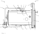
- FIG. 1 is purely schematically illustrated an inventive cooking appliance 1, which has a cooking chamber 2.
- a user can introduce cooking food into the cooking chamber 2 via a cooking chamber opening 10 for cooking.
- the cooking chamber opening 10 can be closed by means of a cooking chamber door 11.
- the cooking appliance 1 is designed as a Kombigarêt 100, in which food can be cooked in the cooking chamber 2 by means of thermal heat sources and / or by means of a steam function.
- a cleaning device 3 is provided in the embodiment shown, which comprises a conveyor 4 for fluid, a distributor 5 and a motor device 7.
- the delivery device comprises a pump 12, which conveys a cleaning fluid via a line 13 to an opening 14 in the cooking space ceiling 15.
- the fluid is passed to a rotating distributor wheel 6 of the distributor 5.
- the distributor wheel 6 is driven by a motor device 7 in the exemplary embodiment shown.
- the fluid conducted onto the distributor wheel 6 is thrown into the cooking chamber 2 or to the cooking chamber wall so that the cooking chamber walls are wetted by the fluid in order to clean the cooking chamber 2.
- a plurality of radially arranged ribs 16 are provided on the upper side of the distributor wheel 7, whereby the distribution of the fluid in the cooking chamber 2 is achieved more effectively and uniformly.
- an outlet 18 is provided in the cooking chamber bottom 17 in the illustrated embodiment, via which a fluid via a line 19 back to the pump 12 and / or can be passed into a spout.
- a closed fluid circuit can be provided so that both a cleaning fluid and a flushing fluid can be recycled or introduced several times via the distributor 6 into the cooking chamber 2.
- a control device 8 is furthermore provided, by means of which the delivery device 4 or the pump 12 can be operated in a clocked manner.
- the motor device 7 is designed such that the rotational speed of the motor device 7 and thus of the distributor wheel 6 is load-dependent.
- the motor device 7 is designed as a gap motor 9.
- the conveyor 4 and the pump 12 are operated in such a timed manner that during a cleaning process, the fluid flow to the spreader 6 is temporarily interrupted completely.
- the speed of the distributor 6 and the motor device is 1000 revolutions per minute. If the fluid flow is interrupted, that is to say the load on the motor device 7 or the distributor wheel 6 is reduced, the rotational speed rises from the control rotational speed to a limiting rotational speed which, in the exemplary embodiment shown here, amounts to 2600 revolutions per minute. Depending on the configuration, other control or limit speeds or differences between them may be provided.
- the speeds may also be smaller or larger, or the difference between the control speed lower limit speed may be different.
- the rotational speed of the distributor wheel increases when the fluid flow is interrupted by the clocked operation of the conveyor 4 or the pump 12, the throwing energy or the throw of the distributor wheel is higher or substantially higher than when the control speed is received again , This ensures that different areas of the cooking chamber wall are hit by rotating in the control speed and the limit speed and the speeds between the limit speed and the control speed distribution wheel.
- the throw height of the fluid can be adjusted, so that by a correspondingly clocked supply of fluid to the spreader a particularly effective and uniform distribution of Fluid in the cooking chamber 2 can be achieved.
- the special design of the cooking appliance 1 according to the invention makes it possible to dispense with the use of expensive pumps with a high performance and the use and / or the use of costly motor devices 7. It can cost and simple components are used, which are anyway present in the cooking appliance 1 by an intended steam function depending on the embodiment.
- the timing of the conveyor 4 or of the pump 12 can also be set via the control device 8 as a function of the speed of the motor device 7 or of the distributor wheel 6. For example, depending on the configuration, it may be provided that the delivery of fluid is restarted as soon as a predetermined limit rotational speed of the engine device 7 is exceeded.
Landscapes
- Chemical & Material Sciences (AREA)
- Engineering & Computer Science (AREA)
- Chemical Kinetics & Catalysis (AREA)
- Combustion & Propulsion (AREA)
- Mechanical Engineering (AREA)
- General Engineering & Computer Science (AREA)
- Cleaning By Liquid Or Steam (AREA)
Applications Claiming Priority (1)
| Application Number | Priority Date | Filing Date | Title |
|---|---|---|---|
| DE102017127113.9A DE102017127113A1 (de) | 2017-11-17 | 2017-11-17 | Gargerät und Verfahren zum Reinigen |
Publications (2)
| Publication Number | Publication Date |
|---|---|
| EP3486571A1 true EP3486571A1 (fr) | 2019-05-22 |
| EP3486571B1 EP3486571B1 (fr) | 2023-06-07 |
Family
ID=64277541
Family Applications (1)
| Application Number | Title | Priority Date | Filing Date |
|---|---|---|---|
| EP18205607.7A Active EP3486571B1 (fr) | 2017-11-17 | 2018-11-12 | Appareil de cuisson et procédé de nettoyage |
Country Status (2)
| Country | Link |
|---|---|
| EP (1) | EP3486571B1 (fr) |
| DE (1) | DE102017127113A1 (fr) |
Cited By (2)
| Publication number | Priority date | Publication date | Assignee | Title |
|---|---|---|---|---|
| EP4119849A1 (fr) | 2021-07-13 | 2023-01-18 | Miele & Cie. KG | Procédé permettant de faire fonctionner un dispositif de nettoyage, appareil de commande et appareil de cuisson pourvu de dispositif de nettoyage et d'appareil de commande |
| DE102022127252A1 (de) | 2022-10-18 | 2024-04-18 | Miele & Cie. Kg | Verteilsystem für ein Gargerät mit einem Garraum und Gargerät |
Families Citing this family (1)
| Publication number | Priority date | Publication date | Assignee | Title |
|---|---|---|---|---|
| DE102021121960A1 (de) | 2021-08-25 | 2022-07-21 | Miele & Cie. Kg | Verteilrad zum Verteilen einer Reinigungsflüssigkeit in einem Garraum eines Gargeräts, Verteilsystem für ein Gargerät, Gargerät und Verfahren zum Betreiben eines Verteilrads |
Citations (6)
| Publication number | Priority date | Publication date | Assignee | Title |
|---|---|---|---|---|
| DE19730610C1 (de) * | 1997-07-17 | 1998-10-22 | Wiesheu Gmbh | Ofen zur Wärmebehandlung von Lebensmitteln und Verfahren zum Reinigen des Innenraums |
| WO2005047773A1 (fr) * | 2003-11-13 | 2005-05-26 | Rational Ag | Procede pour surveiller le remplissage et/ou la charge dans un appareil de cuisson et appareil de cuisson equipe d'une surveillance de remplissage et/ou de charge |
| DE102008025294A1 (de) * | 2008-05-27 | 2009-12-03 | Rational Ag | Verfahren zum Reinigen eines Garraums und Gargerät hierfür |
| US8193470B1 (en) * | 2008-09-08 | 2012-06-05 | Kfc Corporation | Self-cleaning convection oven |
| DE102013021732A1 (de) * | 2013-12-20 | 2015-07-23 | i-clean Technologies GmbH | Reinigungskartusche für Reinigungsvorrichtung in Öfen |
| DE102016100204A1 (de) | 2016-01-06 | 2017-07-06 | Miele & Cie. Kg | Gargerät |
Family Cites Families (1)
| Publication number | Priority date | Publication date | Assignee | Title |
|---|---|---|---|---|
| KR101334611B1 (ko) * | 2013-05-07 | 2013-11-29 | (주)티에스케이에프 | 다기능 오븐의 조리실 자동 세척장치 |
-
2017
- 2017-11-17 DE DE102017127113.9A patent/DE102017127113A1/de not_active Withdrawn
-
2018
- 2018-11-12 EP EP18205607.7A patent/EP3486571B1/fr active Active
Patent Citations (6)
| Publication number | Priority date | Publication date | Assignee | Title |
|---|---|---|---|---|
| DE19730610C1 (de) * | 1997-07-17 | 1998-10-22 | Wiesheu Gmbh | Ofen zur Wärmebehandlung von Lebensmitteln und Verfahren zum Reinigen des Innenraums |
| WO2005047773A1 (fr) * | 2003-11-13 | 2005-05-26 | Rational Ag | Procede pour surveiller le remplissage et/ou la charge dans un appareil de cuisson et appareil de cuisson equipe d'une surveillance de remplissage et/ou de charge |
| DE102008025294A1 (de) * | 2008-05-27 | 2009-12-03 | Rational Ag | Verfahren zum Reinigen eines Garraums und Gargerät hierfür |
| US8193470B1 (en) * | 2008-09-08 | 2012-06-05 | Kfc Corporation | Self-cleaning convection oven |
| DE102013021732A1 (de) * | 2013-12-20 | 2015-07-23 | i-clean Technologies GmbH | Reinigungskartusche für Reinigungsvorrichtung in Öfen |
| DE102016100204A1 (de) | 2016-01-06 | 2017-07-06 | Miele & Cie. Kg | Gargerät |
Cited By (4)
| Publication number | Priority date | Publication date | Assignee | Title |
|---|---|---|---|---|
| EP4119849A1 (fr) | 2021-07-13 | 2023-01-18 | Miele & Cie. KG | Procédé permettant de faire fonctionner un dispositif de nettoyage, appareil de commande et appareil de cuisson pourvu de dispositif de nettoyage et d'appareil de commande |
| DE102021117990A1 (de) | 2021-07-13 | 2023-01-19 | Miele & Cie. Kg | Verfahren zum Betreiben einer Reinigungsvorrichtung, Steuergerät und Gargerät mit Reinigungsvorrichtung und Steuergerät |
| DE102022127252A1 (de) | 2022-10-18 | 2024-04-18 | Miele & Cie. Kg | Verteilsystem für ein Gargerät mit einem Garraum und Gargerät |
| EP4357675A1 (fr) | 2022-10-18 | 2024-04-24 | Miele & Cie. KG | Système de distribution pour un appareil de cuisson doté d'une chambre de cuisson et appareil de cuisson |
Also Published As
| Publication number | Publication date |
|---|---|
| DE102017127113A1 (de) | 2019-05-23 |
| EP3486571B1 (fr) | 2023-06-07 |
Similar Documents
| Publication | Publication Date | Title |
|---|---|---|
| EP3715723B1 (fr) | Appareil de cuisson doté d'une chambre de cuisson, d'un système de distribution et d'un disque de distribution pour un liquide de nettoyage et son procédé de nettoyage | |
| EP3190344B1 (fr) | Appareil de cuisson | |
| EP2495444B1 (fr) | Pompe | |
| EP3486571A1 (fr) | Appareil de cuisson et procédé de nettoyage | |
| DE102007048567B4 (de) | Verfahren zur Reinigung eines Systems, bestehend aus einem Tank und einem Durchlauferhitzer, sowie System | |
| DE102004003126B4 (de) | Ansteuerungsverfahren für Heizelemente und Vorrichtung | |
| DE102014217024A1 (de) | Haushalts-Gargerät mit Dampfeinlass | |
| EP1391141B1 (fr) | Procede et dispositif pour limiter et/ou reguler la temperature superficielle d'une plaque de cuisson | |
| EP3346192B1 (fr) | Appareil de cuisson et procédé de nettoyage | |
| EP3481985B1 (fr) | Appareil de traitement de ligne avec un contrôle | |
| DE102015016247B3 (de) | Heizeinrichtung | |
| EP3885656B1 (fr) | Procédé de nettoyage d'une cavité de cuisson | |
| EP3045820B1 (fr) | Joint de porte pour appareil de cuisson et appareil de cuisson | |
| EP2345350B1 (fr) | Appareil de cuisson | |
| EP2963173B1 (fr) | Procédé de nettoyage d'un fer à repasser à vapeur et d'une centrale vapeur | |
| DE102013110975B4 (de) | Ansteuerung für ein Gargerät | |
| EP3569933A1 (fr) | Appareil acheminant le liquide destiné à la préparation des aliments et / ou des boissons ou au nettoyage d'un article à nettoyer ainsi que son procédé de fonctionnement | |
| DE102010039280A1 (de) | Verfahren zum Durchführen eines Pyrolysevorgangs bei einem Hausgerät | |
| EP2280230B1 (fr) | Procédé de surveillance de l'état de salissure d'un échangeur thermique sur un appareil de chauffage | |
| EP2029943B1 (fr) | Porte de four avec un dispositif de verrouillage | |
| EP1813870A2 (fr) | Appareil de cuisson doté d'une surveillance du remplissage et/ou de la quantité de remplissage | |
| DE102013215847A1 (de) | Verfahren zum Durchführen eines Zubereitungsvorgangs mit einer Absenk-Zeitdauer sowie Gargerät zum Durchführen eines derartigen Verfahrens | |
| DE102018123373A1 (de) | Gargerät, umfassend einen Garraum mit einer Zwischenwand | |
| AT514612B1 (de) | Abluftanlage | |
| EP2762631A1 (fr) | Procédé de fonctionnement d'un lave-linge, dispositif de recirculation et lave-linge |
Legal Events
| Date | Code | Title | Description |
|---|---|---|---|
| PUAI | Public reference made under article 153(3) epc to a published international application that has entered the european phase |
Free format text: ORIGINAL CODE: 0009012 |
|
| STAA | Information on the status of an ep patent application or granted ep patent |
Free format text: STATUS: THE APPLICATION HAS BEEN PUBLISHED |
|
| AK | Designated contracting states |
Kind code of ref document: A1 Designated state(s): AL AT BE BG CH CY CZ DE DK EE ES FI FR GB GR HR HU IE IS IT LI LT LU LV MC MK MT NL NO PL PT RO RS SE SI SK SM TR |
|
| AX | Request for extension of the european patent |
Extension state: BA ME |
|
| STAA | Information on the status of an ep patent application or granted ep patent |
Free format text: STATUS: REQUEST FOR EXAMINATION WAS MADE |
|
| 17P | Request for examination filed |
Effective date: 20191122 |
|
| RBV | Designated contracting states (corrected) |
Designated state(s): AL AT BE BG CH CY CZ DE DK EE ES FI FR GB GR HR HU IE IS IT LI LT LU LV MC MK MT NL NO PL PT RO RS SE SI SK SM TR |
|
| STAA | Information on the status of an ep patent application or granted ep patent |
Free format text: STATUS: EXAMINATION IS IN PROGRESS |
|
| 17Q | First examination report despatched |
Effective date: 20200914 |
|
| GRAP | Despatch of communication of intention to grant a patent |
Free format text: ORIGINAL CODE: EPIDOSNIGR1 |
|
| STAA | Information on the status of an ep patent application or granted ep patent |
Free format text: STATUS: GRANT OF PATENT IS INTENDED |
|
| INTG | Intention to grant announced |
Effective date: 20230222 |
|
| GRAS | Grant fee paid |
Free format text: ORIGINAL CODE: EPIDOSNIGR3 |
|
| GRAA | (expected) grant |
Free format text: ORIGINAL CODE: 0009210 |
|
| STAA | Information on the status of an ep patent application or granted ep patent |
Free format text: STATUS: THE PATENT HAS BEEN GRANTED |
|
| AK | Designated contracting states |
Kind code of ref document: B1 Designated state(s): AL AT BE BG CH CY CZ DE DK EE ES FI FR GB GR HR HU IE IS IT LI LT LU LV MC MK MT NL NO PL PT RO RS SE SI SK SM TR |
|
| REG | Reference to a national code |
Ref country code: GB Ref legal event code: FG4D Free format text: NOT ENGLISH |
|
| REG | Reference to a national code |
Ref country code: CH Ref legal event code: EP Ref country code: AT Ref legal event code: REF Ref document number: 1576128 Country of ref document: AT Kind code of ref document: T Effective date: 20230615 |
|
| REG | Reference to a national code |
Ref country code: DE Ref legal event code: R096 Ref document number: 502018012292 Country of ref document: DE |
|
| REG | Reference to a national code |
Ref country code: NL Ref legal event code: FP |
|
| REG | Reference to a national code |
Ref country code: LT Ref legal event code: MG9D |
|
| PG25 | Lapsed in a contracting state [announced via postgrant information from national office to epo] |
Ref country code: SE Free format text: LAPSE BECAUSE OF FAILURE TO SUBMIT A TRANSLATION OF THE DESCRIPTION OR TO PAY THE FEE WITHIN THE PRESCRIBED TIME-LIMIT Effective date: 20230607 Ref country code: NO Free format text: LAPSE BECAUSE OF FAILURE TO SUBMIT A TRANSLATION OF THE DESCRIPTION OR TO PAY THE FEE WITHIN THE PRESCRIBED TIME-LIMIT Effective date: 20230907 Ref country code: ES Free format text: LAPSE BECAUSE OF FAILURE TO SUBMIT A TRANSLATION OF THE DESCRIPTION OR TO PAY THE FEE WITHIN THE PRESCRIBED TIME-LIMIT Effective date: 20230607 |
|
| PG25 | Lapsed in a contracting state [announced via postgrant information from national office to epo] |
Ref country code: RS Free format text: LAPSE BECAUSE OF FAILURE TO SUBMIT A TRANSLATION OF THE DESCRIPTION OR TO PAY THE FEE WITHIN THE PRESCRIBED TIME-LIMIT Effective date: 20230607 Ref country code: LV Free format text: LAPSE BECAUSE OF FAILURE TO SUBMIT A TRANSLATION OF THE DESCRIPTION OR TO PAY THE FEE WITHIN THE PRESCRIBED TIME-LIMIT Effective date: 20230607 Ref country code: LT Free format text: LAPSE BECAUSE OF FAILURE TO SUBMIT A TRANSLATION OF THE DESCRIPTION OR TO PAY THE FEE WITHIN THE PRESCRIBED TIME-LIMIT Effective date: 20230607 Ref country code: HR Free format text: LAPSE BECAUSE OF FAILURE TO SUBMIT A TRANSLATION OF THE DESCRIPTION OR TO PAY THE FEE WITHIN THE PRESCRIBED TIME-LIMIT Effective date: 20230607 Ref country code: GR Free format text: LAPSE BECAUSE OF FAILURE TO SUBMIT A TRANSLATION OF THE DESCRIPTION OR TO PAY THE FEE WITHIN THE PRESCRIBED TIME-LIMIT Effective date: 20230908 |
|
| PG25 | Lapsed in a contracting state [announced via postgrant information from national office to epo] |
Ref country code: FI Free format text: LAPSE BECAUSE OF FAILURE TO SUBMIT A TRANSLATION OF THE DESCRIPTION OR TO PAY THE FEE WITHIN THE PRESCRIBED TIME-LIMIT Effective date: 20230607 |
|
| PG25 | Lapsed in a contracting state [announced via postgrant information from national office to epo] |
Ref country code: SK Free format text: LAPSE BECAUSE OF FAILURE TO SUBMIT A TRANSLATION OF THE DESCRIPTION OR TO PAY THE FEE WITHIN THE PRESCRIBED TIME-LIMIT Effective date: 20230607 |
|
| PG25 | Lapsed in a contracting state [announced via postgrant information from national office to epo] |
Ref country code: IS Free format text: LAPSE BECAUSE OF FAILURE TO SUBMIT A TRANSLATION OF THE DESCRIPTION OR TO PAY THE FEE WITHIN THE PRESCRIBED TIME-LIMIT Effective date: 20231007 |
|
| PG25 | Lapsed in a contracting state [announced via postgrant information from national office to epo] |
Ref country code: SM Free format text: LAPSE BECAUSE OF FAILURE TO SUBMIT A TRANSLATION OF THE DESCRIPTION OR TO PAY THE FEE WITHIN THE PRESCRIBED TIME-LIMIT Effective date: 20230607 Ref country code: SK Free format text: LAPSE BECAUSE OF FAILURE TO SUBMIT A TRANSLATION OF THE DESCRIPTION OR TO PAY THE FEE WITHIN THE PRESCRIBED TIME-LIMIT Effective date: 20230607 Ref country code: RO Free format text: LAPSE BECAUSE OF FAILURE TO SUBMIT A TRANSLATION OF THE DESCRIPTION OR TO PAY THE FEE WITHIN THE PRESCRIBED TIME-LIMIT Effective date: 20230607 Ref country code: PT Free format text: LAPSE BECAUSE OF FAILURE TO SUBMIT A TRANSLATION OF THE DESCRIPTION OR TO PAY THE FEE WITHIN THE PRESCRIBED TIME-LIMIT Effective date: 20231009 Ref country code: IS Free format text: LAPSE BECAUSE OF FAILURE TO SUBMIT A TRANSLATION OF THE DESCRIPTION OR TO PAY THE FEE WITHIN THE PRESCRIBED TIME-LIMIT Effective date: 20231007 Ref country code: EE Free format text: LAPSE BECAUSE OF FAILURE TO SUBMIT A TRANSLATION OF THE DESCRIPTION OR TO PAY THE FEE WITHIN THE PRESCRIBED TIME-LIMIT Effective date: 20230607 Ref country code: CZ Free format text: LAPSE BECAUSE OF FAILURE TO SUBMIT A TRANSLATION OF THE DESCRIPTION OR TO PAY THE FEE WITHIN THE PRESCRIBED TIME-LIMIT Effective date: 20230607 |
|
| PG25 | Lapsed in a contracting state [announced via postgrant information from national office to epo] |
Ref country code: PL Free format text: LAPSE BECAUSE OF FAILURE TO SUBMIT A TRANSLATION OF THE DESCRIPTION OR TO PAY THE FEE WITHIN THE PRESCRIBED TIME-LIMIT Effective date: 20230607 |
|
| REG | Reference to a national code |
Ref country code: DE Ref legal event code: R097 Ref document number: 502018012292 Country of ref document: DE |
|
| PLBE | No opposition filed within time limit |
Free format text: ORIGINAL CODE: 0009261 |
|
| STAA | Information on the status of an ep patent application or granted ep patent |
Free format text: STATUS: NO OPPOSITION FILED WITHIN TIME LIMIT |
|
| PG25 | Lapsed in a contracting state [announced via postgrant information from national office to epo] |
Ref country code: DK Free format text: LAPSE BECAUSE OF FAILURE TO SUBMIT A TRANSLATION OF THE DESCRIPTION OR TO PAY THE FEE WITHIN THE PRESCRIBED TIME-LIMIT Effective date: 20230607 |
|
| PG25 | Lapsed in a contracting state [announced via postgrant information from national office to epo] |
Ref country code: SI Free format text: LAPSE BECAUSE OF FAILURE TO SUBMIT A TRANSLATION OF THE DESCRIPTION OR TO PAY THE FEE WITHIN THE PRESCRIBED TIME-LIMIT Effective date: 20230607 |
|
| 26N | No opposition filed |
Effective date: 20240308 |
|
| PG25 | Lapsed in a contracting state [announced via postgrant information from national office to epo] |
Ref country code: SI Free format text: LAPSE BECAUSE OF FAILURE TO SUBMIT A TRANSLATION OF THE DESCRIPTION OR TO PAY THE FEE WITHIN THE PRESCRIBED TIME-LIMIT Effective date: 20230607 Ref country code: IT Free format text: LAPSE BECAUSE OF FAILURE TO SUBMIT A TRANSLATION OF THE DESCRIPTION OR TO PAY THE FEE WITHIN THE PRESCRIBED TIME-LIMIT Effective date: 20230607 |
|
| PG25 | Lapsed in a contracting state [announced via postgrant information from national office to epo] |
Ref country code: MC Free format text: LAPSE BECAUSE OF FAILURE TO SUBMIT A TRANSLATION OF THE DESCRIPTION OR TO PAY THE FEE WITHIN THE PRESCRIBED TIME-LIMIT Effective date: 20230607 |
|
| PG25 | Lapsed in a contracting state [announced via postgrant information from national office to epo] |
Ref country code: LU Free format text: LAPSE BECAUSE OF NON-PAYMENT OF DUE FEES Effective date: 20231112 |
|
| PG25 | Lapsed in a contracting state [announced via postgrant information from national office to epo] |
Ref country code: MC Free format text: LAPSE BECAUSE OF FAILURE TO SUBMIT A TRANSLATION OF THE DESCRIPTION OR TO PAY THE FEE WITHIN THE PRESCRIBED TIME-LIMIT Effective date: 20230607 Ref country code: LU Free format text: LAPSE BECAUSE OF NON-PAYMENT OF DUE FEES Effective date: 20231112 |
|
| REG | Reference to a national code |
Ref country code: IE Ref legal event code: MM4A |
|
| PG25 | Lapsed in a contracting state [announced via postgrant information from national office to epo] |
Ref country code: IE Free format text: LAPSE BECAUSE OF NON-PAYMENT OF DUE FEES Effective date: 20231112 |
|
| PG25 | Lapsed in a contracting state [announced via postgrant information from national office to epo] |
Ref country code: IE Free format text: LAPSE BECAUSE OF NON-PAYMENT OF DUE FEES Effective date: 20231112 |
|
| PG25 | Lapsed in a contracting state [announced via postgrant information from national office to epo] |
Ref country code: BG Free format text: LAPSE BECAUSE OF FAILURE TO SUBMIT A TRANSLATION OF THE DESCRIPTION OR TO PAY THE FEE WITHIN THE PRESCRIBED TIME-LIMIT Effective date: 20230607 |
|
| PG25 | Lapsed in a contracting state [announced via postgrant information from national office to epo] |
Ref country code: BG Free format text: LAPSE BECAUSE OF FAILURE TO SUBMIT A TRANSLATION OF THE DESCRIPTION OR TO PAY THE FEE WITHIN THE PRESCRIBED TIME-LIMIT Effective date: 20230607 |
|
| PG25 | Lapsed in a contracting state [announced via postgrant information from national office to epo] |
Ref country code: CY Free format text: LAPSE BECAUSE OF FAILURE TO SUBMIT A TRANSLATION OF THE DESCRIPTION OR TO PAY THE FEE WITHIN THE PRESCRIBED TIME-LIMIT; INVALID AB INITIO Effective date: 20181112 |
|
| PG25 | Lapsed in a contracting state [announced via postgrant information from national office to epo] |
Ref country code: HU Free format text: LAPSE BECAUSE OF FAILURE TO SUBMIT A TRANSLATION OF THE DESCRIPTION OR TO PAY THE FEE WITHIN THE PRESCRIBED TIME-LIMIT; INVALID AB INITIO Effective date: 20181112 |
|
| REG | Reference to a national code |
Ref country code: CH Ref legal event code: U11 Free format text: ST27 STATUS EVENT CODE: U-0-0-U10-U11 (AS PROVIDED BY THE NATIONAL OFFICE) Effective date: 20251201 |
|
| PG25 | Lapsed in a contracting state [announced via postgrant information from national office to epo] |
Ref country code: TR Free format text: LAPSE BECAUSE OF FAILURE TO SUBMIT A TRANSLATION OF THE DESCRIPTION OR TO PAY THE FEE WITHIN THE PRESCRIBED TIME-LIMIT Effective date: 20230607 |
|
| PGFP | Annual fee paid to national office [announced via postgrant information from national office to epo] |
Ref country code: NL Payment date: 20251124 Year of fee payment: 8 |
|
| PGFP | Annual fee paid to national office [announced via postgrant information from national office to epo] |
Ref country code: DE Payment date: 20251130 Year of fee payment: 8 |
|
| PGFP | Annual fee paid to national office [announced via postgrant information from national office to epo] |
Ref country code: GB Payment date: 20251125 Year of fee payment: 8 |
|
| PGFP | Annual fee paid to national office [announced via postgrant information from national office to epo] |
Ref country code: AT Payment date: 20251124 Year of fee payment: 8 |
|
| PGFP | Annual fee paid to national office [announced via postgrant information from national office to epo] |
Ref country code: FR Payment date: 20251124 Year of fee payment: 8 |
|
| PGFP | Annual fee paid to national office [announced via postgrant information from national office to epo] |
Ref country code: BE Payment date: 20251124 Year of fee payment: 8 |
|
| PGFP | Annual fee paid to national office [announced via postgrant information from national office to epo] |
Ref country code: CH Payment date: 20251201 Year of fee payment: 8 |