EP3487103B1 - Procédé, dispositif et système de transmission d'informations d'attribution de programmation - Google Patents
Procédé, dispositif et système de transmission d'informations d'attribution de programmation Download PDFInfo
- Publication number
- EP3487103B1 EP3487103B1 EP16912277.7A EP16912277A EP3487103B1 EP 3487103 B1 EP3487103 B1 EP 3487103B1 EP 16912277 A EP16912277 A EP 16912277A EP 3487103 B1 EP3487103 B1 EP 3487103B1
- Authority
- EP
- European Patent Office
- Prior art keywords
- information
- scheduling assignment
- resource
- domain resource
- multiplexing manner
- Prior art date
- Legal status (The legal status is an assumption and is not a legal conclusion. Google has not performed a legal analysis and makes no representation as to the accuracy of the status listed.)
- Active
Links
Images


Classifications
-
- H—ELECTRICITY
- H04—ELECTRIC COMMUNICATION TECHNIQUE
- H04L—TRANSMISSION OF DIGITAL INFORMATION, e.g. TELEGRAPHIC COMMUNICATION
- H04L5/00—Arrangements affording multiple use of the transmission path
- H04L5/003—Arrangements for allocating sub-channels of the transmission path
- H04L5/0053—Allocation of signalling, i.e. of overhead other than pilot signals
-
- H—ELECTRICITY
- H04—ELECTRIC COMMUNICATION TECHNIQUE
- H04W—WIRELESS COMMUNICATION NETWORKS
- H04W72/00—Local resource management
- H04W72/20—Control channels or signalling for resource management
- H04W72/23—Control channels or signalling for resource management in the downlink direction of a wireless link, i.e. towards a terminal
-
- H—ELECTRICITY
- H04—ELECTRIC COMMUNICATION TECHNIQUE
- H04L—TRANSMISSION OF DIGITAL INFORMATION, e.g. TELEGRAPHIC COMMUNICATION
- H04L5/00—Arrangements affording multiple use of the transmission path
- H04L5/0001—Arrangements for dividing the transmission path
- H04L5/0003—Two-dimensional division
- H04L5/0005—Time-frequency
-
- H—ELECTRICITY
- H04—ELECTRIC COMMUNICATION TECHNIQUE
- H04L—TRANSMISSION OF DIGITAL INFORMATION, e.g. TELEGRAPHIC COMMUNICATION
- H04L5/00—Arrangements affording multiple use of the transmission path
- H04L5/003—Arrangements for allocating sub-channels of the transmission path
- H04L5/0037—Inter-user or inter-terminal allocation
-
- H—ELECTRICITY
- H04—ELECTRIC COMMUNICATION TECHNIQUE
- H04L—TRANSMISSION OF DIGITAL INFORMATION, e.g. TELEGRAPHIC COMMUNICATION
- H04L5/00—Arrangements affording multiple use of the transmission path
- H04L5/003—Arrangements for allocating sub-channels of the transmission path
- H04L5/0058—Allocation criteria
-
- H—ELECTRICITY
- H04—ELECTRIC COMMUNICATION TECHNIQUE
- H04L—TRANSMISSION OF DIGITAL INFORMATION, e.g. TELEGRAPHIC COMMUNICATION
- H04L5/00—Arrangements affording multiple use of the transmission path
- H04L5/0091—Signalling for the administration of the divided path, e.g. signalling of configuration information
- H04L5/0092—Indication of how the channel is divided
-
- H—ELECTRICITY
- H04—ELECTRIC COMMUNICATION TECHNIQUE
- H04L—TRANSMISSION OF DIGITAL INFORMATION, e.g. TELEGRAPHIC COMMUNICATION
- H04L5/00—Arrangements affording multiple use of the transmission path
- H04L5/0091—Signalling for the administration of the divided path, e.g. signalling of configuration information
- H04L5/0094—Indication of how sub-channels of the path are allocated
-
- H—ELECTRICITY
- H04—ELECTRIC COMMUNICATION TECHNIQUE
- H04W—WIRELESS COMMUNICATION NETWORKS
- H04W72/00—Local resource management
- H04W72/12—Wireless traffic scheduling
- H04W72/1263—Mapping of traffic onto schedule, e.g. scheduled allocation or multiplexing of flows
-
- H—ELECTRICITY
- H04—ELECTRIC COMMUNICATION TECHNIQUE
- H04W—WIRELESS COMMUNICATION NETWORKS
- H04W92/00—Interfaces specially adapted for wireless communication networks
- H04W92/16—Interfaces between hierarchically similar devices
-
- H—ELECTRICITY
- H04—ELECTRIC COMMUNICATION TECHNIQUE
- H04W—WIRELESS COMMUNICATION NETWORKS
- H04W92/00—Interfaces specially adapted for wireless communication networks
- H04W92/16—Interfaces between hierarchically similar devices
- H04W92/18—Interfaces between hierarchically similar devices between terminal devices
-
- H—ELECTRICITY
- H04—ELECTRIC COMMUNICATION TECHNIQUE
- H04W—WIRELESS COMMUNICATION NETWORKS
- H04W8/00—Network data management
- H04W8/005—Discovery of network devices, e.g. terminals
Definitions
- the present invention relates to the field of communications technologies, and in particular, to a scheduling assignment information transmission method and system, and a device.
- D2D communication is a communication mode in which two peer terminals directly communicate with each other without using a base station.
- the base station may perform resource configuration, scheduling, coordination, and the like, to assist in direct communication between the terminals.
- the D2D communication includes two characteristics: discovery and communication.
- the discovery means that a terminal periodically broadcasts information, so that a terminal surrounding the terminal may detect the information and discover the terminal.
- the communication means that direct data transmission is performed between terminals, and a mechanism of scheduling assignment (SA)+data is used.
- SA scheduling assignment
- the SA is used to indicate status information of data sent by a transmit end, and the status information includes time-frequency resource information, modulation and coding scheme (MCS) information, frequency hopping indication information, timing advance information, and receiving group ID information, and the like of the data, so that a receive end can receive service data based on the formation indicated by the SA.
- the data is service data sent by the transmit end based on the time-frequency resource information indicated by the SA and in a format indicated by the SA.
- the base station configures a transmission resource pool (for example, an SA resource pool and a data resource pool) for the terminal, so that the terminal performs data transmission of the D2D communication.
- the terminal may perform D2D transmission by using a time-frequency resource configured by the base station for the terminal in the resource pool, or may independently and randomly select a time-frequency resource from a configured resources for D2D transmission.
- the Internet of Vehicles may implement interconnection and interworking of vehicle-to-vehicle (V2V), vehicle-to-roadside (V2R), vehicle-to-Internet (Vehicle-to-Internet, V2I), vehicle-to-human (V2H), and the like.
- V2V vehicle-to-vehicle
- V2R vehicle-to-roadside
- Vehicle-to-Internet V2I
- V2H vehicle-to-human
- a cellular network technology is used for V2V communication in the Internet of Vehicles, so that a base station may be fully used to dynamically schedule a transmission resource, a communication conflict probability is reduced, and a problem of delay uncontrollability is resolved.
- a base station mainly performs transmission resource configuration, interference coordination, and the like. Because vehicle-to-vehicle communication in an Internet of Vehicles system is also terminal-to-terminal communication, the V2V communication may be considered as the D2D communication.
- a method for indicating an SA time-frequency resource by the base station in D2D communication is not applicable to the V2V communication.
- There are a plurality of multiplexing manners for the SA and the data in the V2V communication and the multiplexing manner is used to describe a relationship between a time-frequency resource for transmitting the SA and a time-frequency resource for transmitting the data.
- the multiplexing manner is used to indicate whether the SA and the data are transmitted in different subframes or in a same subframe, or the like.
- the plurality of multiplexing manners for the SA and the data do not exist in the D2D communication. Therefore, if the method for indicating the SA time-frequency resource by the base station in the D2D communication is still used in the V2V communication, a resource occupied to transmit SA information cannot be accurately indicated or obtained, and transmission performance is affected.
- WO2016019557A1 discloses that in step S303, the base station through the downlink control information or a bit filed of said higher layer signaling indicating the UE a scheduling assignment data with respect to the time unit difference between the number of time domain. Since the resource allocation scheduling grant and information data are base stations simultaneously direct and the terminal has many possible resource allocation, and therefore, the base station also indicates the data with respect to the scheduling assignment time difference, so that, the UE can be based on the scheduling assignment time unit number(index) to determine the following data unit of time (number), preclude the frequency domain resource base station transmits scheduling assignment instructions and data, respectively.
- WO2015184916A1 discloses that receive data scheduling indication information delivered by a base station, where the data scheduling indication information is used to indicate a transmission mode of SA and Data. Send SA and Data to the peer user equipment according to the data scheduling indication information.
- EP3481125A1 discloses that there is little possibility that a size (e.g., 6 bits) of the field indicating the SA resource defined in the existing DCI format with the change of the scheme of multiplexing SA and/or data (e.g., Frequency Division Multiplexing (FDM) scheme and Time Division Multiplexing (TDM) scheme) only.
- a size e.g., 6 bits
- FDM Frequency Division Multiplexing
- TDM Time Division Multiplexing
- EP3402276A1 discloses a method for transmitting data and control information by a terminal in a wireless communication system, the method comprising the steps of: determining subframes in which a scheduling assignment (SA) is to be transmitted in an SA resource pool; and transmitting data by means of resources indicated by a combination of a time resource indication field and information related to the determined subframes.
- SA scheduling assignment
- T-RPT length L should be defined to have values L ⁇ M, where M is the number of subframes in the SA pool, such that k receptions of SA can be transmitted in time-multiplexed or time-frequency multiplexed manner.
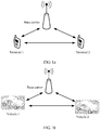
- FIG. 1a is a network architectural diagram of D2D communication, including a terminal 1, a terminal 2, and a base station.
- a terminal In actual application, a plurality of terminals are included in a coverage area of one base station.
- the terminal may include an electronic device having a communication function, such as a mobile phone, a tablet computer (Pad), or an intelligent wearable device (such as a watch or a band). It can be seen from FIG. 1a that both terminals may directly communicate with the base station, and communication may also be performed between the two terminals in the D2D communication.
- a communication function such as a mobile phone, a tablet computer (Pad), or an intelligent wearable device (such as a watch or a band).
- the D2D communication includes two characteristics: discovery and communication.
- the discovery means that a terminal periodically broadcasts information, so that a terminal surrounding the terminal may detect the information and discover the terminal.
- the communication means that direct data transmission is performed between terminals, and a mechanism of scheduling assignment (SA)+data is used.
- SA is used to indicate status information of data sent by a transmit end, and the status information includes time-frequency resource information, MCS information, frequency hopping indication information, timing advance information, and receiving group ID information, and the like of the data, so that a receive end can receive service data based on the formation indicated by the SA.
- the data is service data sent by the transmit end based on the time-frequency resource information indicated by the SA and in a format indicated by the SA.
- the base station configures a transmission resource pool (for example, an SA resource pool and a data resource pool) for the terminal, so that the terminal performs data transmission of the D2D communication.
- the terminal may perform D2D transmission by using a time-frequency resource configured by the base station for the terminal in the resource pool, or may independently and randomly select a time-frequency resource from a configured resource for D2D transmission.
- the base station allocates, to the terminal by using downlink control information (DCI), a time-frequency resource for transmitting the SA and the data in the resource pool.
- DCI downlink control information
- the DCI includes an index field (six bits), a time resource pattern of transmission (T-RPT) field, and a resource assignment (RA) field.
- the index field is used to indicate an SA time-frequency resource
- the T-RPT field is used to indicate a time domain resource of the data
- the RA field is used to indicate a frequency domain resource of the data.
- FIG. 1b is a network architectural diagram of V2V communication, including a vehicle 1, a vehicle 2, and a base station.
- a plurality of vehicles are included in a coverage area of one base station.
- IC in cell coverage
- OOC out of cell coverage
- FIG. 1b describes a scenario of in cell coverage.
- the vehicle 1 and the vehicle 2 are within a coverage area of the base station.
- Out of cell coverage means that vehicles communicate with each other outside a coverage area of the base station.
- a vehicle in cell coverage detects a synchronization signal sent by the base station, obtains time-frequency synchronization and a cell ID, detects a physical broadcast channel (PBCH), obtains information such as bandwidth of a system, a quantity of antennas, a radio frame number, and physical hybrid automatic repeat request indicator channel (PHICH) configuration. Based on the information, the vehicle may perform control channel detection, periodically receive another broadcast message from the system, and perform normal communication transmission.
- the base station mainly performs transmission resource assignment, interference coordination, and the like. Before performing data transmission, the vehicle first applies to the base station for a transmission resource, and reports status information of the vehicle to the base station, and the base station allocates a corresponding resource to the vehicle based on the information reported by the vehicle.
- the V2V communication is also terminal-to-terminal communication, and therefore may be considered as a D2D communications technology.
- a method for indicating the SA time-frequency resource by the base station in the D2D communication is not applicable to the V2V communication.
- the multiplexing manner is used to describe a relationship between the time-frequency resource for transmitting the SA and the time-frequency resource for transmitting the data.
- the multiplexing manner is used to indicate whether the SA and the data are transmitted in different subframes or in a same subframe, or the like.
- the plurality of multiplexing manners for the SA and the data do not exist in the D2D communication. Therefore, if the method for indicating the SA time-frequency resource by the base station in the D2D communication is still used in the V2V communication, a resource occupied to transmit SA information cannot be accurately indicated or obtained, and transmission performance is affected.
- an embodiment of the present invention provides a scheduling assignment information transmission method, to consider the plurality of multiplexing manners, accurately indicate or obtain a resource occupied to transmit scheduling assignment information, and further improve transmission performance.
- the scheduling assignment information transmission method provided in this embodiment of the present invention may be applied to a communication scenario in which there are a plurality of multiplexing manners, and the communication scenario may include but is not limited to an Internet of Vehicles scenario (a scenario of communication between a base station, a roadside unit, a motor vehicle, a non-motor vehicle, a pedestrian, and another communications device on a road). Further, this embodiment of the present invention may be further applied to an Internet of Things scenario, and specifically, may be applied to a scenario of communication between intelligent household appliances.
- an Internet of Vehicles scenario a scenario of communication between a base station, a roadside unit, a motor vehicle, a non-motor vehicle, a pedestrian, and another communications device on a road.
- this embodiment of the present invention may be further applied to an Internet of Things scenario, and specifically, may be applied to a scenario of communication between intelligent household appliances.
- a user equipment in this embodiment of the present invention includes both the terminal described in FIG. 1a and an electronic device such as a motor vehicle, a non-motor vehicle, another communications device on a road, or an intelligent household appliance.
- a network device in this embodiment of the present invention may include but is not limited to a base station device, a roadside unit, and a network side device in future 5G communications.
- scheduling assignment information and SA are interchangeable, and data information and the data are interchangeable.
- FIG. 2 is a schematic flowchart of a scheduling assignment information transmission method according to an embodiment of the present invention. It should be noted that description is given by using transmission of one piece of scheduling assignment information as an example in this embodiment of the present invention. A same transmission method is used for each piece of scheduling assignment information, and the scheduling assignment information and data information are transmitted in pairs. A specific procedure of the scheduling assignment information transmission method is described from perspectives of both a user equipment and a network device in the embodiment shown in FIG. 2 . The method may include the following steps.
- the network device configures a multiplexing manner for the user equipment.
- the three multiplexing manners are used to describe a relationship between a time-frequency resource for transmitting scheduling assignment information and a time-frequency resource for transmitting data information.
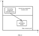
- the three multiplexing manners include a first multiplexing manner shown in FIG. 4 , a second multiplexing manner shown in FIG. 6 , and a third multiplexing manner shown in FIG. 7 .
- the first multiplexing manner is used to indicate that a time domain resource for transmitting the scheduling assignment information is different from a time domain resource for transmitting the data information.
- the scheduling assignment information and the data information are transmitted in different subframes.
- a frequency domain resource of the scheduling assignment information may be adjacent or not adjacent to a frequency domain resource of the data information.
- time domain resources occupy different subframes, and frequency domain resources are not adjacent.
- the second multiplexing manner is used to indicate that a time domain resource for transmitting the scheduling assignment information is the same as a time domain resource for transmitting the data information, and a frequency domain resource for transmitting the scheduling assignment information is not adjacent to a frequency domain resource for transmitting the data information.
- the scheduling assignment information and the data information are transmitted in a same subframe, and the frequency domain resource for transmitting the scheduling assignment information is not adjacent to the frequency domain resource for transmitting the data information.
- the third multiplexing manner is used to indicate that a time domain resource for transmitting the scheduling assignment information is the same as a time domain resource for transmitting the data information, and a frequency domain resource for transmitting the scheduling assignment information is adjacent to a frequency domain resource for transmitting the data information.
- the scheduling assignment information and the data information are transmitted in a same subframe, and the frequency domain resource for transmitting the scheduling assignment information is adjacent to the frequency domain resource for transmitting the data information.
- the network device configures the multiplexing manner for the user equipment by configuring different multiplexing manners for different resource pools. Specifically, the network device configures a plurality of resource pools, each resource pool includes a configuration parameter, and the configuration parameter includes an SA resource pool configuration parameter, a data resource pool configuration parameter, and a multiplexing manner configuration parameter.
- the multiplexing manner configuration parameter is used to indicate the multiplexing manner, and may indicate one or more multiplexing manners.
- the network device notifies the user equipment of an identifier (for example, a sequence number, an ID, and a name) of a resource pool allocated to the user equipment.
- the user equipment uses the resource pool based on the identifier of the resource pool, and obtains a multiplexing manner configuration parameter corresponding to the resource pool, so as to obtain, based on the multiplexing manner configuration parameter, a multiplexing manner indicated by the multiplexing manner configuration parameter.
- the network device sends messages such as an RRC message, a MAC layer message, and a physical layer message to the user equipment, to notify the user equipment of the identifier of the resource pool allocated to the user equipment. It may be understood that the possible implementation is an explicit notification manner.
- the network device sends DCI to the user equipment.
- the DCI includes data information resource indication information, and indicates a time-frequency resource location occupied to transmit the data information.
- the user equipment obtains the time-frequency resource location occupied to transmit the data information, determines a used resource pool based on the time-frequency resource location occupied to transmit the data information, obtains a configuration parameter corresponding to the resource pool, and obtains a multiplexing manner configuration parameter from the configuration parameter, so as to obtain, based on the multiplexing manner configuration parameter, a multiplexing manner indicated by the multiplexing manner configuration parameter.
- the possible implementation is an implicit notification manner.
- the network device configures the multiplexing manner for the user equipment by configuring different multiplexing manners for different cells. Specifically, the network device configures multiplexing manners for different cells in a coverage area. In a configuration process, one cell may be configured with one or more multiplexing manners, but resource pools in one cell have a same multiplexing manner. For example, a multiplexing manner of each resource pool in a cell 1 is the first multiplexing manner.
- the network device sends multiplexing indication information to the user equipment based on a cell accessed by the user equipment, so that the user equipment can obtain the multiplexing manner.
- the multiplexing indication information may include messages such as an RRC message, a MAC layer message, and a physical layer message.
- the network device configures preconfiguration information for the user equipment, and the preconfiguration information indicates the multiplexing manner.
- the preconfiguration information indicates the multiplexing manner by additionally adding an information element to a resource pool configuration parameter.
- the preconfiguration information is notified to the user equipment by sending messages such as an RRC message, a MAC layer message, and a physical layer message to the user equipment.
- the network device sends the multiplexing indication information or another message to the user equipment by using an air interface between the network device and the user equipment.
- the user equipment obtains the multiplexing manner.
- the user equipment receives the multiplexing indication information sent by the network device, and obtains the multiplexing manner based on the multiplexing indication information.
- the multiplexing indication information may include the messages such as the RRC message, the MAC layer message, and the physical layer message.
- the user equipment receives, by using the air interface between the user equipment and the network device, the multiplexing indication information sent by the network device.
- the user equipment receives the messages such as the RRC message, the MAC layer message, and the physical layer message that are sent by the network device.
- the messages include the identifier of the resource pool allocated by the network device to the user equipment.
- the user equipment obtains, based on the identifier of the resource pool, the multiplexing manner configuration parameter corresponding to the resource pool, so as to obtain, based on the multiplexing manner configuration parameter, the multiplexing manner indicated by the multiplexing manner configuration parameter.
- the user equipment receives the DCI sent by the network device.
- the DCI includes the data information resource indication information, and indicates the time-frequency resource location occupied to transmit the data information.
- the user equipment obtains the time-frequency resource location occupied to transmit the data information, determines the used resource pool based on the time-frequency resource location occupied to transmit the data information, obtains the configuration parameter corresponding to the resource pool, and obtains the multiplexing manner configuration parameter from the configuration parameter, so as to obtain, based on the multiplexing manner configuration parameter, the multiplexing manner indicated by the multiplexing manner configuration parameter.
- the user equipment obtains the multiplexing manner based on the preconfiguration information, and the preconfiguration information is used to indicate the multiplexing manner.
- the preconfiguration information may be configured by the network device for the user equipment, or may be configured by a manufacturer of the user equipment for the user equipment before delivery. However, the preconfiguration information is on the user equipment. If the preconfiguration information is configured by the manufacturer, the multiplexing manner of the user equipment is fixed; or if the preconfiguration information is configured by the network device, the network device may change the multiplexing manner of the user equipment.
- the preconfiguration information indicates the multiplexing manner by additionally adding an information element to the resource pool configuration parameter.
- the network device sends downlink control information to the user equipment based on the multiplexing manner, where the downlink control information includes scheduling assignment resource indication information.
- the network device sends the downlink control information DCI to the user equipment based on the multiplexing manner and by using the air interface between the network device and the user equipment.
- the DCI includes the scheduling assignment resource indication information, and the scheduling assignment resource indication information is used to indicate resource location information occupied to transmit the scheduling assignment information.
- the scheduling assignment resource indication information indicates different resource location information based on different multiplexing manners, so that the scheduling assignment resource indication information is pertinent, and the resource location information indicated by the scheduling assignment resource indication information is more accurate, and closer to an actual application scenario.
- the scheduling assignment resource indication information is used to indicate a time domain resource location and a frequency domain resource location that are occupied to transmit the scheduling assignment information.
- the scheduling assignment resource indication information includes scheduling assignment time domain resource indication information and scheduling assignment frequency domain resource indication information.
- the scheduling assignment time domain resource indication information is used to indicate the time domain resource location occupied to transmit the scheduling assignment information
- the scheduling assignment frequency domain resource indication information is used to indicate the frequency domain resource location occupied to transmit the scheduling assignment information.
- the scheduling assignment time domain resource indication information is used to indicate a relationship (for example, a subframe interval) between the time domain resource location occupied to transmit the scheduling assignment information and a time domain resource location occupied to transmit the data information
- the scheduling assignment time domain resource indication information is used to indicate a relationship (for example, a frequency offset) between the frequency domain resource location occupied to transmit the scheduling assignment information and a frequency domain resource location occupied to transmit the data information, so as to indirectly indicate, with reference to the data information resource indication information, the time domain resource location and the frequency domain resource location that are occupied to transmit the scheduling assignment information.
- the scheduling assignment resource indication information indicates both the time domain resource location and the frequency domain resource location that are occupied to transmit the scheduling assignment information, or indicates both the relationship between the time domain resource location occupied to transmit the scheduling assignment information and the time domain resource location occupied to transmit the data information, and the relationship between the time domain resource location occupied to transmit the scheduling assignment information and the time domain resource location occupied to transmit the data information.
- the scheduling assignment resource indication information is used to indicate a frequency domain resource location occupied to transmit the scheduling assignment information. If the multiplexing manner is the third multiplexing manner, the scheduling assignment resource indication information is used to indicate a relationship between a frequency domain resource location occupied to transmit the scheduling assignment information and a frequency domain resource location occupied to transmit the data information.
- the scheduling assignment resource indication information only needs to indicate the frequency domain resource location occupied to transmit the scheduling assignment information. Therefore, indication information redundancy can be avoided, and signaling overheads can be reduced.
- the user equipment receives the downlink control information sent by the network device.
- the user equipment receives, by using the air interface between the user equipment and the network device, the downlink control information sent by the network device, and extracts the scheduling assignment resource indication information from the downlink control information.
- the user equipment obtains, based on the scheduling assignment resource indication information and the multiplexing manner, resource location information occupied to transmit the scheduling assignment information.
- the scheduling assignment resource indication information indicates the time domain resource location and the frequency domain resource location that are occupied to transmit the scheduling assignment information
- the user equipment may directly obtain, based on the scheduling assignment resource indication information and the first multiplexing manner, the time domain resource location and the frequency domain resource location that are occupied to transmit the scheduling assignment information.
- the scheduling assignment resource indication information indicates the frequency domain resource location occupied to transmit the scheduling assignment information, and does not indicate the time domain resource location occupied to transmit the scheduling assignment information. Therefore, the user equipment needs to obtain the time domain resource location occupied to transmit the scheduling assignment information.
- the downlink control information includes data resource indication information in addition to the scheduling assignment resource indication information.
- the data resource indication information includes a T-RPT field and an RA field.
- the T-RPT field indicates the time domain resource location occupied to transmit the data information
- the RA field indicates a frequency domain resource location occupied to transmit the data information.
- the user equipment obtains, based on the data resource indication information, the time domain resource location occupied to transmit the data information.
- the user equipment determines that the time domain resource location occupied to transmit the data information is the time domain resource location occupied to transmit the scheduling assignment information.
- the user equipment obtains, based on the second multiplexing manner and the scheduling assignment resource indication information, the frequency domain resource location occupied to transmit the scheduling assignment information.
- the scheduling assignment resource indication information indicates the relationship between the frequency domain resource location occupied to transmit the scheduling assignment information and the frequency domain resource location occupied to transmit the data information.
- the relationship between the frequency domain resource locations may indicate that the scheduling assignment information is transmitted on a side of the data information, or may be transmitted on another side of the data information.
- neither the frequency domain resource location occupied to transmit the scheduling assignment information nor the time domain resource location occupied to transmit the scheduling assignment information is clearly indicated. Therefore, the user equipment needs to obtain the time frequency resource location and the frequency domain resource location that are occupied to transmit the scheduling assignment information.
- the downlink control information includes data resource indication information in addition to the scheduling assignment resource indication information.
- the data resource indication information includes a T-RPT field and an RA field.
- the T-RPT field indicates the time domain resource location occupied to transmit the data information
- the RA field indicates the frequency domain resource location occupied to transmit the data information.
- the user equipment obtains, based on the data resource indication information, the time domain resource location and the frequency domain resource location that are occupied to transmit the data information. Because the scheduling assignment information and the data information are transmitted in a same subframe, the user equipment determines that the time domain resource location occupied to transmit the data information is the time domain resource location occupied to transmit the scheduling assignment information. The user equipment obtains, based on the third multiplexing manner and the relationship between the frequency domain resource locations that is indicated by the scheduling assignment resource indication information, the frequency domain resource location occupied to transmit the scheduling assignment information.
- the time domain resource location occupied to transmit the data information is the same as the time domain resource location occupied to transmit the scheduling assignment information
- indication information used to indicate the time domain resource location occupied to transmit the scheduling assignment information does not need to be configured in the downlink control information. Therefore, indication information redundancy can be avoided, and signaling overheads can be reduced.
- the downlink control information further includes transmission quantity indication information, the transmission quantity indication information is used to indicate that a quantity of transmission times of the scheduling assignment information is at least one time, and the scheduling assignment resource indication information is used to indicate resource location information occupied to transmit the scheduling assignment information each of the at least one time, so as to more accurately indicate the resource location information occupied to transmit the scheduling assignment information.
- the scheduling assignment information is permanently transmitted for two times, and data is permanently transmitted for four times.
- data is not permanently transmitted for four times, and a quantity of transmission times of the data is changeable, for example, two times, six times, or eight times.
- the scheduling assignment information may be transmitted for a same quantity of times as the data, and the quantity of transmission times of the scheduling assignment information is also not permanently two times. Because the scheduling assignment information and the data have a same quantity of transmission times, the transmission quantity indication information may be transmission quantity indication information of the scheduling assignment information, or may be transmission quantity indication information of the data. Only one piece of the transmission quantity indication information is required, to avoid information redundancy. Therefore, the scheduling assignment resource indication information needs to clearly indicate the resource location information occupied to transmit the scheduling assignment information each time.
- the user equipment transmits the scheduling assignment information based on the resource location information occupied by the scheduling assignment information.
- the user equipment transmits the scheduling assignment information by using the time domain resource location and the frequency domain resource location that are occupied by the scheduling assignment information and a transmission interface between user equipments.
- the scheduling assignment information is transmitted to other user equipment, so that data information transmission can be performed between the two user equipments, and direct communication can be performed between the two user equipments.
- the network device configures the multiplexing manner for the user equipment, and sends, based on the multiplexing manner, the downlink control information that includes the scheduling assignment resource indication information to the user equipment; the user equipment obtains the multiplexing manner, receives the downlink control information that includes the scheduling assignment resource indication information and that is sent by the network device, obtains, based on the scheduling assignment resource indication information and the multiplexing manner, the resource location information occupied to transmit the scheduling assignment information, and transmits the scheduling assignment information based on the resource location information occupied by the scheduling assignment information, so that a resource occupied to transmit the scheduling assignment information can be accurately indicated or obtained, and transmission performance can be further improved.
- a time-frequency resource location occupied by scheduling assignment information is described in detail below with reference to FIG. 3 to FIG. 7 .
- FIG. 3 is a schematic diagram of a time-frequency resource location of scheduling assignment information in D2D communication. It should be noted that the schematic diagram of the time-frequency resource location shown in FIG. 3 is merely used as an example for description, and does not constitute a limitation on the embodiments of the present invention.
- SA is permanently transmitted for two times, and data is permanently transmitted for four times.
- L PSCCH represents a time domain length (a quantity of subframes) of an SA resource pool
- M RB PSCCH _ RP represents a frequency domain length of the SA resource pool
- a frequency domain length unit is a resource block (RB).
- a specific learning manner is not limited herein, and no example is used for the learning manner.
- PSCCH is a physical sidelink control channel (PSCCH).
- n PSCCH represents a value indicated by an index field.
- frequency domain resource locations are respectively a 1 and a 2
- time domain resource locations are respectively b 1 and b 2 .
- a value range that can be indicated by the index field is 0 to 9.
- a digit shown in each grid in FIG. 3 is the value indicated by the index field. It can be seen from FIG.
- the first row and the second row may be represented as a time-frequency resource location occupied for the first SA transmission
- the third row and the fourth row may be represented as a time-frequency resource location occupied for second SA transmission.
- a frequency domain resource occupied for one time of SA transmission is an RB 0, namely, a 1 in FIG. 3
- a time domain resource is a subframe 3, namely, b 1 in FIG. 3
- a frequency domain resource occupied for the other time of SA transmission is an RB 2, namely, a 2 in FIG. 3
- a time domain resource is a subframe 4, namely, b 2 in FIG. 3 .
- a resource location occupied by the scheduling assignment information is described below by using an example in which a quantity of transmission times is 1, 2, or 4.
- a manner of indicating the SA time-frequency resource location in the D2D communication is still used, but only a time-frequency resource for one time of SA transmission is used.
- a time-frequency resource location indicated by a 1 and b 1 is used.
- the user equipment calculates, according to the foregoing formulas, the frequency domain resource locations a 1 and a 2 and the time domain resource locations b 1 and b 2 that are occupied for the two times of SA transmission.
- the SA is transmitted only on an SA resource indicated by a 1 and b 1
- the SA is transmitted only on an SA resource indicated by a 2 and b 2 .
- the SA resource may be indicated in DCI, for example, by using one bit; or may be indicated by using an independent field in DCI; or may be indicated by extending scheduling assignment resource indication information.
- the SA resource may be indicated by using RRC signaling, for example, RRC dedicated signaling or a system message.
- indication information may be added to the RRC signaling.
- the SA resource may be indicated by using one bit. In a possible implementation, when the indication information is 0, an SA resource whose subscript is 1 is indicated; and when the indication information is 1, an SA resource whose subscript is 2 is indicated.
- the user equipment may calculate only a time domain resource location and a frequency domain resource location of a required SA resource. For example, when learning that the SA resource whose subscript is 1 is used, the user equipment only calculates a 1 and b 1 by using the value indicated by the index field, and does not need to calculate a 2 and b 2 .
- the user equipment calculates, according to the foregoing formulas, the frequency domain resource locations a 1 and a 2 and the time domain resource locations b 1 and b 2 that are occupied for the two times of SA transmission, and transmits the SA on these two SA resources.
- two RBs may be occupied for one time of SA transmission in frequency domain in V2V communication, and two RBs may be used as a basic unit to redivide the SA resource pool.
- a frequency domain parameter in the formulas needs to be interpreted by using two RBs as a basic unit.
- M RB PSCCH _ RP represents a quantity of basic units (two RBs) in frequency domain instead of a quantity of RBs in the SA resource pool in frequency domain.
- the frequency domain resource locations indicated by a 1 and a 2 for the two times of transmission also need to be interpreted by using two RBs as a granularity.
- time-frequency resources for the four times of transmission are obtained by extending an indication manner of the two times of SA transmission. Specifically, when learning the value indicated by the index field and learning that the quantity of transmission times is 4, the UE calculates, in the following manners, frequency domain resource locations a 1 - a 4 and time domain resource locations b 1 - b 4 for the four times of SA transmission, and transmits the SA on these resources.
- Specific extension manners are as follows:
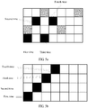
- FIG. 5a is a schematic diagram of a time-frequency resource location in the first multiplexing manner. Uniform space translation is performed on time-frequency resource locations for the two times of transmission in time domain, so as to obtain time-frequency resource locations for the other two times of transmission.
- black grids in FIG. 5a respectively represent resources occupied for four times of SA transmission.
- Resources occupied for first two times of transmission are resources occupied for the two times of transmission.
- a frequency domain resource occupied for the third transmission is the same as that occupied for the first transmission, and a frequency domain resource occupied for the fourth transmission is the same as that occupied for the second transmission.
- FIG. 5b is a schematic diagram of another time-frequency resource location in the first multiplexing manner.
- Uniform space translation is performed on a time-frequency resource location for the first of the two times of transmission in time domain and frequency domain, so as to obtain time-frequency resource locations for the other three times of transmission.
- black grids in FIG. 5b respectively represent resources for the four times of SA transmission.
- a resource for the first transmission is a resource for the first of the two times of transmission, and there is a difference of one between time-frequency resource locations for every two times of subsequent transmission.
- an advantage of Manner 2 is that even if two UEs whose quantities of SA transmission times are respectively 2 and 4 select same SA resource indication information, a problem that all resources collide does not occur. It is assumed that SA of a user equipment 1 is transmitted for two times, and SA of a user equipment 2 is transmitted for four times. When the two user equipments have same SA resource indication information:
- FIG. 5c is a schematic diagram of still another time-frequency resource location in the first multiplexing manner. It is assumed that time domain resources for the second transmission and the third transmission in Manner 2 are unchanged, and frequency domain resources are exchanged with each other.
- an advantage of Manner 3 is that both quantities of SA transmission times of two user equipments are 4, but the two user equipments select different SA resource indication information, and certainly no resource collision occurs. It is assumed that both SA of a user equipment 1 and SA of a user equipment 2 are transmitted for four times. When the two user equipments have different SA resource indication information:
- FIG. 5d is a schematic diagram of yet another time-frequency resource location in the first multiplexing manner.
- Different time domain transmission intervals are allocated to different quantities of transmission times.
- time domain intervals may be 1 or 2 for two times of transmission, and time domain intervals may be 3 for four times of transmission.
- Manner 4 In comparison with Manner 1, Manner 2, and Manner 3, an advantage of Manner 4 is that even if two user equipments whose quantities of SA transmission times are respectively 2 and 4 select same SA resource indication information, no half-duplex problem occurs, and consequently, a user equipment whose quantity of transmission times is 4 completely receives no SA of a user equipment whose quantity of transmission times is 2. It is assumed that SA of a user equipment 1 is transmitted for four times, and SA of a user equipment 2 is transmitted for two times. When the two user equipments have same SA resource indication information:
- a same time domain resource is used for first two times of transmission of the user equipment 1 and two times of transmission of the user equipment 2. Because a user equipment cannot perform sending and receiving at a same moment, the user equipment 1 misses two times of SA transmission of the user equipment 2.
- the user equipment whose quantity of transmission times is 4 has at least one opportunity to receive SA of the user equipment whose quantity of transmission times is 2.
- Manner 5 It is assumed that during all times of transmission in Manner 1 to Manner 4, time domains are unchanged and frequency domains are symmetric. Manner 4 is used as an example. Referring to FIG. 5e, FIG. 5e is a schematic diagram of still yet another time-frequency resource location in the first multiplexing manner.
- a resource location occupied by the scheduling assignment information is described below by using an example in which a quantity of transmission times is 1, 2, or 4.
- Manner 1 SA resource indication information in the first multiplexing manner shown in FIG. 4 is reused, but only frequency domain resource information in the SA resource indication information is used.
- the SA resource indication information in the first multiplexing manner shown in FIG. 4 indicates a time domain resource location and a frequency domain resource location that are occupied to transmit the SA. It is only considered herein that the frequency domain resource location information in the SA resource indication information is meaningful, and time domain resource location information is ignored.
- the SA is transmitted for four times, and a resource indicated by the SA resource indication information is shown in the following figure.
- Time domain resource locations are a zeroth time domain resource, a first time domain resource, a second time domain resource, and a third time domain resource
- frequency domain resource locations are a zeroth frequency domain resource, a second frequency domain resource, a first frequency domain resource, and a third frequency domain resource.
- the user equipment uses only the frequency domain resource location information, determines that frequency domain resource locations for the four times of SA transmission are the zeroth frequency domain resource, the second frequency domain resource, the first frequency domain resource, and the third frequency domain resource, and ignores the time domain resource location information.
- Manner 1 An advantage of Manner 1 is simplicity, and the SA resource indication information in the first multiplexing manner shown in FIG. 4 is directly reused without needing to make any change to the information. There are only some differences when the user equipment interprets the information.
- Manner 2 Redefine SA resource indication information, so that the SA resource indication information indicates only frequency domain resource information.
- a frequency domain resource location for subsequent transmission is determined by a frequency domain resource location for first transmission.
- the SA resource indication information only needs to indicate the frequency domain resource location for the first transmission. For example, when the SA resource indication information is 0, it indicates that a zeroth frequency domain resource is used for the first transmission; and when the SA resource indication information is 1, it indicates that a first frequency domain resource is used.
- a network device sends the information to the user equipment. After receiving the information, the user equipment may calculate, based on the information, K, and M, a frequency domain resource location for each time of transmission. The following steps may be used:
- step (iii) and the step (iv) are used; or when the quantity of transmission times is 1, only the step (iv) is used, and so on.
- a network device sends the information to the user equipment. After receiving the information, the user equipment may calculate, based on the information, K, and M, a frequency domain resource location for each time of transmission. The following steps may be used:
- the step (i) and the step (ii) are used; or when the quantity of transmission times is 1, only the step (i) is used, and so on.
- an index field is six bits, may support a maximum of 64 (2 6 ) different possibilities, and may indicate a maximum of 64 different values.
- the SA resource indication information may have a larger value.
- more bits are allocated to the SA resource indication information, for example, seven or eight bits.
- six bits are still used for the SA resource indication information.
- a manner described in the following (3) is used.
- frequency domain resource locations for a relatively small quantity of transmission times are defined by using (2), and frequency domain resource locations for a larger quantity of transmission times are obtained by performing repeated extension.
- frequency domain resource locations are defined by using (2) (a total quantity of possibilities is less than 64, and six bits may still be used).
- frequency domain resource locations for excessive transmission may be obtained by using frequency domain resource locations for first three times of transmission (for example, repetition or symmetry).
- the quantity of transmission times is 4, a frequency domain resource used for the fourth transmission is the same as that for the first transmission, or a same frequency domain resource is used for the fourth transmission and the third transmission, and so on.
- SA resource indication information may be used to indicate a specific side of the data on which the SA is located (for example, indicate whether the SA is on an upside or a downside of the data).
- the quantity of transmission times is more than 1, there may be a fixed relationship between relative locations of SA frequency domain resources for all times of transmission, and a relative location for subsequent SA transmission may be completely determined by a relative location for first SA transmission.
- a same relative location is used for each time of transmission. For example, when the SA is on the upside of the data for first transmission, the SA is on the upside of the data for each subsequent transmission.
- each time of transmission has a fixed mode.
- the SA is transmitted for four times.
- locations relative to the data for the second transmission, the third transmission, and the fourth transmission are respectively the downside, the upside, and the downside, and so on.
- the quantity of transmission times is more than 1, there may be no fixed relationship between relative locations of SA frequency domain resources for all times of transmission.
- the SA may be on the upside or may be on the downside relative to the data, but whether the SA is on the upside or on the downside for each time of transmission is completely indicated by using the SA resource indication information.
- the SA when the SA is transmitted for four times, four bits may be used in the SA resource indication information to indicate a frequency domain relative location for each time of SA transmission relative to the data.
- a case in which there is another quantity of transmission times is similar. For example, when the quantity of transmission times is 2, only first two times of transmission in the foregoing description are considered.
- SA resource indication information may be used to indicate one or more SA resources used by the SA.
- three SA resources may be used, and may be numbered 0, 1, and 2.
- the SA resource indication information indicates that a middle SA resource (an SA resource 1) is used.
- SA resource 1 When the quantity of transmission times is more than 1, there may be a fixed relationship between relative locations of SA frequency domain resources for all times of transmission. A relative location for subsequent SA transmission may be completely determined by a relative location for first SA transmission. Alternatively, there may be no fixed relationship. In other words, any SA resource may be used for each time of SA transmission, and this is indicated by the SA resource indication information.
- relative locations of an SA frequency domain resource and a data frequency domain resource may also be fixed.
- the SA uses an upmost SA resource regardless of whether the data occupies consecutive RBs. This may be fixed in a protocol, or may be preconfigured on the user equipment, or may be configured by the network device by using an RRC message (system broadcast, RRC dedicated signaling, or the like). In this case, the SA resource indication information does not need to give an indication.
- each device such as a user equipment or a network device includes a corresponding hardware structure and/or software module for performing each function.
- each device such as a user equipment or a network device includes a corresponding hardware structure and/or software module for performing each function.
- a person skilled in the art should be easily aware that with reference to units and algorithm steps in the examples described in the embodiments disclosed in this specification, the present invention can be implemented in a form of hardware or a combination of hardware and computer software. Whether a function is performed by hardware or hardware driven by computer software depends on particular applications and design constraints of the technical solutions. A person skilled in the art may use different methods to implement the described functions for each particular application, but it should not be considered that the implementation goes beyond the scope of the present invention.
- function unit division may be performed on the user equipment, the network device, and the like based on the foregoing method example.
- each function unit may be obtained through division based on a corresponding function, or two or more functions may be integrated into one processing unit.
- the integrated unit may be implemented in a form of hardware, or may be implemented in a form of a software functional unit.
- the unit division in the embodiments of the present invention is an example, and is only logical function division. There may be another division manner in actual implementation.
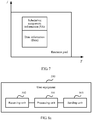
- FIG. 8a shows a possible schematic structural diagram of the user equipment in the foregoing embodiments.
- a user equipment 500 includes a processing unit 501, a receiving unit 502, and a sending unit 503.
- the processing unit 501 is configured to obtain a multiplexing manner.
- the multiplexing manner is used to indicate a relationship between a time-frequency resource for transmitting scheduling assignment information and a time-frequency resource for transmitting data information.
- the receiving unit 502 is configured to receive downlink control information sent by a network device.
- the downlink control information includes scheduling assignment resource indication information.
- the processing unit 501 is further configured to obtain, based on the scheduling assignment resource indication information and the multiplexing manner, resource location information occupied to transmit the scheduling assignment information.
- the sending unit 503 is configured to transmit the scheduling assignment information based on the resource location information occupied by the scheduling assignment information.
- the multiplexing manner includes at least one of a first multiplexing manner, a second multiplexing manner, and a third multiplexing manner, the first multiplexing manner indicates that a time domain resource for transmitting the scheduling assignment information is different from a time domain resource for transmitting the data information, the second multiplexing manner indicates that a time domain resource for transmitting the scheduling assignment information is the same as a time domain resource for transmitting the data information, and a frequency domain resource for transmitting the scheduling assignment information is not adjacent to a frequency domain resource for transmitting the data information, and the third multiplexing manner indicates that a time domain resource for transmitting the scheduling assignment information is the same as a time domain resource for transmitting the data information, and a frequency domain resource for transmitting the scheduling assignment information is adjacent to a frequency domain resource for transmitting the data information.
- the scheduling assignment resource indication information is used to indicate a time domain resource location and a frequency domain resource location that are occupied to transmit the scheduling assignment information; or if the multiplexing manner is the second multiplexing manner, the scheduling assignment resource indication information is used to indicate a frequency domain resource location occupied to transmit the scheduling assignment information; or if the multiplexing manner is the third multiplexing manner, the scheduling assignment resource indication information is used to indicate a relationship between a frequency domain resource location occupied to transmit the scheduling assignment information and a frequency domain resource location occupied to transmit the data information.
- the processing unit 501 is configured to obtain, based on the scheduling assignment resource indication information and the first multiplexing manner, the time domain resource location and the frequency domain resource location that are occupied to transmit the scheduling assignment information.
- the processing unit 501 is configured to obtain, based on the scheduling assignment resource indication information and the second multiplexing manner, the frequency domain resource location occupied to transmit the scheduling assignment information.
- the processing unit 501 is further configured to: obtain a time domain resource location occupied to transmit the data information, and determine that the time domain resource location occupied to transmit the data information is a time domain resource location occupied to transmit the scheduling assignment information.
- the processing unit 501 is configured to: obtain a time domain resource location and the frequency domain resource location that are occupied to transmit the data information, and determine that the time domain resource location for transmitting the data information is a time domain resource location occupied to transmit the scheduling assignment information.
- the processing unit 501 is further configured to obtain, based on the scheduling assignment resource indication information, the third multiplexing manner, and the frequency domain resource location of the data information, the frequency domain resource location occupied to transmit the scheduling assignment information.
- the downlink control information further includes transmission quantity indication information, the transmission quantity indication information is used to indicate that a quantity of transmission times of the scheduling assignment information is at least one time, and the scheduling assignment resource indication information is used to indicate resource location information occupied to transmit the scheduling assignment information each of the at least one time.
- the processing unit 501 is configured to obtain the multiplexing manner based on received multiplexing indication information sent by the network device, where the multiplexing indication information is used to indicate the multiplexing manner; or the processing unit is configured to obtain the multiplexing manner based on preconfiguration information, where the preconfiguration information is used to indicate the multiplexing manner.
- processing unit 501 is configured to perform steps 102 and 105 in the embodiment shown in FIG. 2
- receiving unit 502 is configured to perform step 104 in the embodiment shown in FIG. 2
- sending unit 503 is configured to perform step 106 in the embodiment shown in FIG. 2 .
- the processing unit 501 may be a processor or a controller, for example, may be a central processing unit (CPU), a general purpose processor, a digital signal processor (DSP), an application-specific integrated circuit (ASIC), a field programmable gate array (FPGA) or another programmable logic component, a transistor logic component, a hardware component, or any combination thereof.
- the processing unit 501 may implement or execute various example logical blocks, modules, and circuits described with reference to content disclosed in the present invention.
- the processor may be a combination that implements a computing function, for example, a combination that includes one or more microprocessors, or a combination of the DSP and a microprocessor.
- the receiving unit 502 and the sending unit 503 maybe transceivers, transceiver circuits, communications modules, or the like.
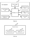
- the user equipment in the embodiments of the present invention may be a user equipment shown in FIG. 8b .
- the user equipment 510 includes: a power supply 511, a user interface 512, a communications module 513, a processor 514, a display system 515, a sensing system 516, and an audio system 517.
- the user equipment 510 may represent the terminal in FIG. 1a , or may represent an electronic device such as a motor vehicle, a non-motor vehicle, another communications device on a road, or an intelligent household appliance.
- a structure of the user equipment shown in FIG. 8b does not constitute a limitation on the embodiments of the present invention.
- the power supply 511 guarantees power for implementing various functions of the user equipment 510.
- the user interface 512 is configured to connect the user equipment 510 and another device or apparatus, to implement communication or data transmission between the another device or apparatus and the user equipment 510.
- the communications module 513 is configured to implement communication or data transmission between the user equipment 510 and a network side device such as a base station and a satellite, and is further configured to implement communication or data transmission between the user equipment 510 and other user equipment. In the embodiments of the present invention, the communications module 513 is configured to implement functions of the receiving unit 502 and the sending unit 503 shown in FIG. 8a .
- the processor 514 may implement or execute various example logical blocks, modules, and circuits described with reference to content disclosed in the present invention.
- the processor 514 is configured to implement a function of the processing unit 501 shown in FIG. 8a .
- the display system 515 is configured to output and display information, and receive a user-inputted operation.
- the sensing system 516 includes various sensors such as a temperature sensor, a distance sensor, and the like.
- the audio system 517 is configured to output an audio signal.
- FIG. 9a shows a possible schematic structural diagram of the network device in the foregoing embodiments.
- a network device 600 includes a processing unit 601 and a sending unit 602.
- the processing unit 601 is adapted to configure a multiplexing manner for a user equipment.
- the multiplexing manner is used to indicate a relationship between a time-frequency resource for transmitting scheduling assignment information and a time-frequency resource for transmitting data information.
- the sending unit 602 is configured to send downlink control information to the user equipment based on the multiplexing manner.
- the downlink control information includes scheduling assignment resource indication information, and the scheduling assignment resource indication information is used to indicate resource location information occupied to transmit the scheduling assignment information.
- the multiplexing manner includes at least one of a first multiplexing manner, a second multiplexing manner, and a third multiplexing manner, the first multiplexing manner indicates that a time domain resource for transmitting the scheduling assignment information is different from a time domain resource for transmitting the data information, the second multiplexing manner indicates that a time domain resource for transmitting the scheduling assignment information is the same as a time domain resource for transmitting the data information, and a frequency domain resource for transmitting the scheduling assignment information is not adjacent to a frequency domain resource for transmitting the data information, and the third multiplexing manner indicates that a time domain resource for transmitting the scheduling assignment information is the same as a time domain resource for transmitting the data information, and a frequency domain resource for transmitting the scheduling assignment information is adjacent to a frequency domain resource for transmitting the data information.
- the scheduling assignment resource indication information is used to indicate a time domain resource location and a frequency domain resource location that are occupied to transmit the scheduling assignment information; or if the multiplexing manner is the second multiplexing manner, the scheduling assignment resource indication information is used to indicate a frequency domain resource location occupied to transmit the scheduling assignment information; or if the multiplexing manner is the third multiplexing manner, the scheduling assignment resource indication information is used to indicate a relationship between a frequency domain resource location occupied to transmit the scheduling assignment information and a frequency domain resource location occupied to transmit the data information.
- the downlink control information further includes transmission quantity indication information, the transmission quantity indication information is used to indicate that a quantity of transmission times of the scheduling assignment information is at least one time, and the scheduling assignment resource indication information is used to indicate resource location information occupied to transmit the scheduling assignment information each of the at least one time.
- the sending unit 602 is further configured to send multiplexing indication information to the user equipment based on the multiplexing manner.
- the multiplexing indication information is used to indicate the multiplexing manner.
- processing unit 601 is configured to perform step 101 in the embodiment shown in FIG. 2
- sending unit 602 is configured to perform step 103 in the embodiment shown in FIG. 2 .
- the processing unit 601 may be a processor or a controller, for example, may be a CPU, a general purpose processor, a DSP, an ASIC, an FPGA, or another programmable logic device, a transistor logic device, a hardware component, or any combination thereof.
- the processing unit 601 may implement or execute various example logical blocks, modules, and circuits described with reference to content disclosed in the present invention.
- the processor may be a combination that implements a computing function, for example, a combination that includes one or more microprocessors, or a combination of the DSP and a microprocessor.
- the sending unit 602 may be a transceiver, a transceiver circuit, a communications interface, or the like.
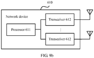
- the network device in the embodiments of the present invention may be a network device shown in FIG. 9b .
- the network device 610 includes a processor 611, a transceiver 612, and an antenna. It should be noted that in actual application, a quantity of the transceivers 612 is not limited to two, a quantity of the antennas is not limited to two, and a structure of the network device 610 does not constitute a limitation on the embodiments of the present invention.
- the processor 610 mainly includes four components: a cell controller, a voice channel controller, a signaling channel controller, and a multi-port interface for expansion.
- the processor 610 is responsible for managing all mobile communications interfaces, and is mainly responsible for radio channel allocation, release, and management.
- the processor 610 is configured to implement a function of the processing unit 601 shown in FIG. 9a in the embodiments of the present invention.
- the transceiver 612 includes a receiver and a transmitter. A user equipment may transmit uplink data by using the transmitter, and receive downlink data by using the receiver.
- the transceiver 612 is configured to implement a function of the sending unit 602 shown in FIG. 9a in the embodiments of the present invention.
- An embodiment of the present invention further provides a computer storage medium, configured to store a computer software instruction used by the user equipment, where the computer software instruction includes a program designed to execute the foregoing aspects.
- An embodiment of the present invention further provides a computer storage medium, configured to store a computer software instruction used by the network device, where the computer software instruction includes a program designed to execute the foregoing aspects.
- An embodiment of the present invention further provides a scheduling assignment information transmission system, including the user equipment shown in FIG. 8a and the network device shown in FIG. 9a , or the user equipment shown in FIG. 8b , and the network device shown in FIG. 9b .
- the steps of the method in the embodiments of the present invention may be sequentially adjusted, combined, or deleted based on an actual requirement.
- the present invention may be implemented by hardware, firmware or a combination thereof.
- the foregoing functions may be stored in a computer-readable medium or transmitted as one or more instructions or code in the computer-readable medium.
- the computer-readable medium includes a computer storage medium and a communications medium, and the communications medium includes any medium that enables a computer program to be transmitted from one place to another.
- the storage medium may be any available medium accessible to a computer.
- the computer readable medium may include a random access memory (RAM), a read-only memory (ROM), an electrically erasable programmable read-only memory (EEPROM), a compact disc read-only memory (CD-ROM) or other optical disk storage, a disk storage medium or other disk storage, or any other medium that can be used to carry or store expected program code in a command or data structure form and can be accessed by a computer.
- RAM random access memory
- ROM read-only memory
- EEPROM electrically erasable programmable read-only memory
- CD-ROM compact disc read-only memory
- any connection may be appropriately defined as a computer-readable medium.
- a disk and disc used by the present invention includes a compact disc (CD), a laser disc, an optical disc, a digital versatile disc (DVD), a floppy disk and a Blu-ray disc.
- the disk generally copies data by a magnetic means, and the disc copies data optically by a laser means.
Landscapes
- Engineering & Computer Science (AREA)
- Signal Processing (AREA)
- Computer Networks & Wireless Communication (AREA)
- Mobile Radio Communication Systems (AREA)
Claims (16)
- Procédé de transmission d'informations d'attribution d'ordonnancement pour communication dispositif-à-dispositif, le procédé comprenant :l'obtention (102), par un équipement utilisateur, d'une manière de multiplexage, dans lequel la manière de multiplexage est utilisée pour indiquer une relation entre une ressource temps-fréquence pour transmettre des informations d'attribution d'ordonnancement et une ressource temps-fréquence pour transmettre des informations de données, dans lequel la manière de multiplexage indique qu'une ressource de domaine temporel pour transmettre les informations d'attribution d'ordonnancement est la même qu'une ressource de domaine temporel pour transmettre les informations de données, et une ressource de domaine fréquentiel pour transmettre les informations d'attribution d'ordonnancement n'est pas adjacente à une ressource de domaine fréquentiel pour transmettre les informations de données, ou la manière de multiplexage indique qu'une ressource de domaine temporel pour transmettre les informations d'attribution d'ordonnancement est la même qu'une ressource de domaine temporel pour transmettre les informations de données, et une ressource de domaine fréquentiel pour transmettre les informations d'attribution d'ordonnancement est adjacente à une ressource de domaine fréquentiel pour transmettre les informations de données ;la réception (104), par l'équipement utilisateur, d'informations de commande de liaison descendante envoyées par un dispositif de réseau, dans lequel les informations de commande de liaison descendante comprennent des informations d'indication de ressource d'attribution d'ordonnancement ;l'obtention (105), par l'équipement utilisateur, sur la base des informations d'indication de ressource d'attribution d'ordonnancement et de la manière de multiplexage, d'informations de localisation de ressource occupées pour transmettre les informations d'attribution d'ordonnancement ; etla transmission (106), par l'équipement utilisateur, des informations d'attribution d'ordonnancement sur la base des informations de localisation de ressource occupées par les informations d'attribution d'ordonnancement.
- Procédé selon la revendication 1, dans lequel, si la manière de multiplexage est la première manière de multiplexage, les informations d'indication de ressource d'attribution d'ordonnancement sont utilisées pour indiquer une localisation de ressource de domaine temporel et une localisation de ressource de domaine fréquentiel qui sont occupées pour transmettre les informations d'attribution d'ordonnancement ; ou, si la manière de multiplexage est la deuxième manière de multiplexage, les informations d'indication de ressource d'attribution d'ordonnancement sont utilisées pour indiquer une localisation de ressource de domaine fréquentiel occupée pour transmettre les informations d'attribution d'ordonnancement ; ou, si la manière de multiplexage est la troisième manière de multiplexage, les informations d'indication de ressource d'attribution d'ordonnancement sont utilisées pour indiquer une relation entre une localisation de ressource de domaine fréquentiel occupée pour transmettre les informations d'attribution d'ordonnancement et une localisation de ressource de domaine fréquentiel occupée pour transmettre les informations de données.
- Procédé selon la revendication 1, dans lequel les informations de commande de liaison descendante comprennent en outre des informations d'indication de quantité de transmission, les informations d'indication de quantité de transmission sont utilisées pour indiquer qu'une quantité de transmissions des informations d'attribution d'ordonnancement est d'au moins une fois, et les informations d'indication de ressource d'attribution d'ordonnancement sont utilisées pour indiquer des informations de localisation de ressource occupées pour transmettre les informations d'attribution d'ordonnancement chacune de l'au moins une fois.
- Procédé selon la revendication 1, dans lequel l'obtention, par un équipement utilisateur, d'une manière de multiplexage comprend :l'obtention, par l'équipement utilisateur, de la manière de multiplexage sur la base d'informations d'indication de multiplexage reçues envoyées par le dispositif de réseau, dans lequel les informations d'indication de multiplexage sont utilisées pour indiquer la manière de multiplexage ; oul'obtention, par l'équipement utilisateur, de la manière de multiplexage sur la base d'informations de pré-configuration, dans lequel les informations de pré-configuration sont utilisées pour indiquer la manière de multiplexage.
- Procédé de transmission d'informations d'attribution d'ordonnancement pour communication dispositif-à-dispositif, le procédé comprenant :la configuration (101), par un dispositif de réseau, d'une manière de multiplexage pour un équipement utilisateur, dans lequel la manière de multiplexage est utilisée pour indiquer une relation entre une ressource temps-fréquence pour transmettre des informations d'attribution d'ordonnancement et une ressource temps-fréquence pour transmettre des informations de données, dans lequel la manière de multiplexage indique qu'une ressource de domaine temporel pour transmettre les informations d'attribution d'ordonnancement est la même qu'une ressource de domaine temporel pour transmettre les informations de données, et une ressource de domaine fréquentiel pour transmettre les informations d'attribution d'ordonnancement n'est pas adjacente à une ressource de domaine fréquentiel pour transmettre les informations de données, ou la manière de multiplexage indique qu'une ressource de domaine temporel pour transmettre les informations d'attribution d'ordonnancement est la même qu'une ressource de domaine temporel pour transmettre les informations de données, et une ressource de domaine fréquentiel pour transmettre les informations d'attribution d'ordonnancement est adjacente à une ressource de domaine fréquentiel pour transmettre les informations de données ; etl'envoi (103), par le dispositif de réseau, d'informations de commande de liaison descendante à l'équipement utilisateur sur la base de la manière de multiplexage, dans lequel les informations de commande de liaison descendante comprennent des informations d'indication de ressource d'attribution d'ordonnancement, et les informations d'indication de ressource d'attribution d'ordonnancement sont utilisées pour indiquer des informations de localisation de ressource occupées pour transmettre les informations d'attribution d'ordonnancement.
- Procédé selon la revendication 5, dans lequel, si la manière de multiplexage est la première manière de multiplexage, les informations d'indication de ressource d'attribution d'ordonnancement sont utilisées pour indiquer une localisation de ressource de domaine temporel et une localisation de ressource de domaine fréquentiel qui sont occupées pour transmettre les informations d'attribution d'ordonnancement ; ou, si la manière de multiplexage est la deuxième manière de multiplexage, les informations d'indication de ressource d'attribution d'ordonnancement sont utilisées pour indiquer une localisation de ressource de domaine fréquentiel occupée pour transmettre les informations d'attribution d'ordonnancement ; ou, si la manière de multiplexage est la troisième manière de multiplexage, les informations d'indication de ressource d'attribution d'ordonnancement sont utilisées pour indiquer une relation entre une localisation de ressource de domaine fréquentiel occupée pour transmettre les informations d'attribution d'ordonnancement et une localisation de ressource de domaine fréquentiel occupée pour transmettre les informations de données.
- Procédé selon la revendication 5, dans lequel les informations de commande de liaison descendante comprennent en outre des informations d'indication de quantité de transmission, les informations d'indication de quantité de transmission sont utilisées pour indiquer qu'une quantité de transmissions des informations d'attribution d'ordonnancement est d'au moins une fois, et les informations d'indication de ressource d'attribution d'ordonnancement sont utilisées pour indiquer des informations de localisation de ressource occupées pour transmettre les informations d'attribution d'ordonnancement chacune de l'au moins une fois.
- Procédé selon la revendication 5, avant l'envoi, par le dispositif de réseau, des informations de commande de liaison descendante à l'équipement utilisateur sur la base de la manière de multiplexage, comprenant en outre :
l'envoi, par le dispositif de réseau, d'informations d'indication de multiplexage à l'équipement utilisateur sur la base de la manière de multiplexage, dans lequel les informations d'indication de multiplexage sont utilisées pour indiquer la manière de multiplexage. - Équipement utilisateur (500), comprenant :une unité de traitement (501), configurée pour obtenir une manière de multiplexage pour communication dispositif-à-dispositif, dans lequel la manière de multiplexage est utilisée pour indiquer une relation entre une ressource temps-fréquence pour transmettre des informations d'attribution d'ordonnancement et une ressource temps-fréquence pour transmettre des informations de données, dans lequel la manière de multiplexage indique qu'une ressource de domaine temporel pour transmettre les informations d'attribution d'ordonnancement est la même qu'une ressource de domaine temporel pour transmettre les informations de données, et une ressource de domaine fréquentiel pour transmettre les informations d'attribution d'ordonnancement n'est pas adjacente à une ressource de domaine fréquentiel pour transmettre les informations de données, ou la manière de multiplexage indique qu'une ressource de domaine temporel pour transmettre les informations d'attribution d'ordonnancement est la même qu'une ressource de domaine temporel pour transmettre les informations de données, et une ressource de domaine fréquentiel pour transmettre les informations d'attribution d'ordonnancement est adjacente à une ressource de domaine fréquentiel pour transmettre les informations de données ;une unité de réception (502), configurée pour recevoir des informations de commande de liaison descendante envoyées par un dispositif de réseau, dans lequel les informations de commande de liaison descendante comprennent des informations d'indication de ressource d'attribution d'ordonnancement, dans lequell'unité de traitement est en outre configurée pour obtenir, sur la base des informations d'indication de ressource d'attribution d'ordonnancement et de la manière de multiplexage, des informations de localisation de ressource occupées pour transmettre les informations d'attribution d'ordonnancement ; etune unité d'envoi (503), configurée pour transmettre les informations d'attribution d'ordonnancement sur la base des informations de localisation de ressource occupées par les informations d'attribution d'ordonnancement.
- Équipement utilisateur selon la revendication 9, dans lequel, si la manière de multiplexage est la première manière de multiplexage, les informations d'indication de ressource d'attribution d'ordonnancement sont utilisées pour indiquer une localisation de ressource de domaine temporel et une localisation de ressource de domaine fréquentiel qui sont occupées pour transmettre les informations d'attribution d'ordonnancement ; ou, si la manière de multiplexage est la deuxième manière de multiplexage, les informations d'indication de ressource d'attribution d'ordonnancement sont utilisées pour indiquer une localisation de ressource de domaine fréquentiel occupée pour transmettre les informations d'attribution d'ordonnancement ; ou, si la manière de multiplexage est la troisième manière de multiplexage, les informations d'indication de ressource d'attribution d'ordonnancement sont utilisées pour indiquer une relation entre une localisation de ressource de domaine fréquentiel occupée pour transmettre les informations d'attribution d'ordonnancement et une localisation de ressource de domaine fréquentiel occupée pour transmettre les informations de données.
- Équipement utilisateur selon la revendication 9, dans lequel les informations de commande de liaison descendante comprennent en outre des informations d'indication de quantité de transmission, les informations d'indication de quantité de transmission sont utilisées pour indiquer qu'une quantité de transmissions des informations d'attribution d'ordonnancement est d'au moins une fois, et les informations d'indication de ressource d'attribution d'ordonnancement sont utilisées pour indiquer des informations de localisation de ressource occupées pour transmettre les informations d'attribution d'ordonnancement chacune de l'au moins une fois.
- Équipement utilisateur selon la revendication 9, dans lequel l'unité de traitement est configurée pour obtenir la manière de multiplexage sur la base d'informations d'indication de multiplexage reçues envoyées par le dispositif de réseau, dans lequel les informations d'indication de multiplexage sont utilisées pour indiquer la manière de multiplexage ; ou l'unité de traitement est configurée pour obtenir la manière de multiplexage sur la base d'informations de pré-configuration, dans lequel les informations de pré-configuration sont utilisées pour indiquer la manière de multiplexage.
- Dispositif de réseau (600), comprenant :une unité de traitement (601), adaptée pour configurer une manière de multiplexage pour communication dispositif-à-dispositif pour un équipement utilisateur,dans lequel la manière de multiplexage est utilisée pour indiquer une relation entre une ressource temps-fréquence pour transmettre des informations d'attribution d'ordonnancement et une ressource temps-fréquence pour transmettre des informations de données, dans lequel la manière de multiplexage indique qu'une ressource de domaine temporel pour transmettre les informations d'attribution d'ordonnancement est la même qu'une ressource de domaine temporel pour transmettre les informations de données, et une ressource de domaine fréquentiel pour transmettre les informations d'attribution d'ordonnancement n'est pas adjacente à une ressource de domaine fréquentiel pour transmettre les informations de données, ou la manière de multiplexage indique qu'une ressource de domaine temporel pour transmettre les informations d'attribution d'ordonnancement est la même qu'une ressource de domaine temporel pour transmettre les informations de données, et une ressource de domaine fréquentiel pour transmettre les informations d'attribution d'ordonnancement est adjacente à une ressource de domaine fréquentiel pour transmettre les informations de données ; etune unité d'envoi (602), configurée pour envoyer des informations de commande de liaison descendante à l'équipement utilisateur sur la base de la manière de multiplexage, dans lequel les informations de commande de liaison descendante comprennent des informations d'indication de ressource d'attribution d'ordonnancement, et les informations d'indication de ressource d'attribution d'ordonnancement sont utilisées pour indiquer des informations de localisation de ressource occupées pour transmettre les informations d'attribution d'ordonnancement.
- Dispositif de réseau selon la revendication 13, dans lequel, si la manière de multiplexage est la première manière de multiplexage, les informations d'indication de ressource d'attribution d'ordonnancement sont utilisées pour indiquer une localisation de ressource de domaine temporel et une localisation de ressource de domaine fréquentiel qui sont occupées pour transmettre les informations d'attribution d'ordonnancement ; ou, si la manière de multiplexage est la deuxième manière de multiplexage, les informations d'indication de ressource d'attribution d'ordonnancement sont utilisées pour indiquer une localisation de ressource de domaine fréquentiel occupée pour transmettre les informations d'attribution d'ordonnancement ; ou, si la manière de multiplexage est la troisième manière de multiplexage, les informations d'indication de ressource d'attribution d'ordonnancement sont utilisées pour indiquer une relation entre une localisation de ressource de domaine fréquentiel occupée pour transmettre les informations d'attribution d'ordonnancement et une localisation de ressource de domaine fréquentiel occupée pour transmettre les informations de données.
- Dispositif de réseau selon la revendication 13, dans lequel les informations de commande de liaison descendante comprennent en outre des informations d'indication de quantité de transmission, les informations d'indication de quantité de transmission sont utilisées pour indiquer qu'une quantité de transmissions des informations d'attribution d'ordonnancement est d'au moins une fois, et les informations d'indication de ressource d'attribution d'ordonnancement sont utilisées pour indiquer des informations de localisation de ressource occupées pour transmettre les informations d'attribution d'ordonnancement chacune de l'au moins une fois.
- Dispositif de réseau selon la revendication 13, dans lequel l'unité d'envoi est en outre configurée pour envoyer des informations d'indication de multiplexage à l'équipement utilisateur sur la base de la manière de multiplexage, dans lequel les informations d'indication de multiplexage sont utilisées pour indiquer la manière de multiplexage.
Applications Claiming Priority (1)
| Application Number | Priority Date | Filing Date | Title |
|---|---|---|---|
| PCT/CN2016/094713 WO2018027822A1 (fr) | 2016-08-11 | 2016-08-11 | Procédé, dispositif et système de transmission d'informations d'attribution de programmation |
Publications (3)
| Publication Number | Publication Date |
|---|---|
| EP3487103A1 EP3487103A1 (fr) | 2019-05-22 |
| EP3487103A4 EP3487103A4 (fr) | 2019-08-21 |
| EP3487103B1 true EP3487103B1 (fr) | 2021-07-07 |
Family
ID=61161555
Family Applications (1)
| Application Number | Title | Priority Date | Filing Date |
|---|---|---|---|
| EP16912277.7A Active EP3487103B1 (fr) | 2016-08-11 | 2016-08-11 | Procédé, dispositif et système de transmission d'informations d'attribution de programmation |
Country Status (7)
| Country | Link |
|---|---|
| US (1) | US11272528B2 (fr) |
| EP (1) | EP3487103B1 (fr) |
| JP (1) | JP2019525648A (fr) |
| KR (1) | KR20190032573A (fr) |
| CN (1) | CN109478964B (fr) |
| BR (1) | BR112019002362A2 (fr) |
| WO (1) | WO2018027822A1 (fr) |
Families Citing this family (7)
| Publication number | Priority date | Publication date | Assignee | Title |
|---|---|---|---|---|
| CA3012395C (fr) | 2016-01-27 | 2020-10-27 | Huawei Technologies Co., Ltd. | Methode de communication et appareil de communication |
| CN110808817B (zh) | 2018-08-06 | 2021-01-26 | 维沃移动通信有限公司 | 资源配置方法和装置 |
| CN111328041A (zh) * | 2018-12-13 | 2020-06-23 | 普天信息技术有限公司 | 车联网v2x的资源复用模式指示方法及装置 |
| CN112583523B (zh) * | 2019-09-30 | 2022-04-15 | 大唐移动通信设备有限公司 | 一种传输模式的指示方法、装置、基站、终端及存储介质 |
| KR102322347B1 (ko) * | 2019-12-27 | 2021-11-05 | 서울대학교산학협력단 | 차량 간 통신에서 혼잡 제어를 위한 주기적 메시지 전송 방법 및 장치 |
| MX2022010010A (es) * | 2020-02-14 | 2022-11-10 | Huawei Tech Co Ltd | Método de indicación de recursos, método de determinación de recursos, y aparato. |
| CN114258724B (zh) * | 2020-07-23 | 2025-07-08 | 北京小米移动软件有限公司 | 逻辑信道复用方法及装置、通信设备及存储介质 |
Family Cites Families (100)
| Publication number | Priority date | Publication date | Assignee | Title |
|---|---|---|---|---|
| CN103493525B (zh) * | 2011-03-25 | 2016-06-08 | 北京新岸线移动多媒体技术有限公司 | 无线通信系统、网络设备及终端设备 |
| TWI620459B (zh) * | 2012-05-31 | 2018-04-01 | 內數位專利控股公司 | 在蜂巢式通訊系統中賦能直鏈通訊排程及控制方法 |
| WO2015021185A1 (fr) * | 2013-08-07 | 2015-02-12 | Interdigital Patent Holdings, Inc. | Planification distribuée pour une communication de dispositif à dispositif |
| CN104812084A (zh) * | 2014-01-28 | 2015-07-29 | 中兴通讯股份有限公司 | 配置信息的发送、获取方法、接入方法、通信节点及系统 |
| EP3122109A4 (fr) * | 2014-03-20 | 2018-02-28 | Kyocera Corporation | Procédé de commande de communication et terminal utilisateur |
| US10419175B2 (en) * | 2014-03-20 | 2019-09-17 | Lg Electronics Inc. | Method for transmitting D2D signal in wireless communication system and device therefor |
| WO2015142066A1 (fr) * | 2014-03-20 | 2015-09-24 | 엘지전자(주) | Procédé d'émission et de réception de signal dans un système de communication sans fil, et dispositif associé |
| WO2015152580A1 (fr) * | 2014-03-30 | 2015-10-08 | 엘지전자(주) | Procédé permettant d'émettre et de recevoir un signal dans un système de communication sans fil et appareil associé |
| EP3133843B1 (fr) * | 2014-04-13 | 2018-12-12 | LG Electronics Inc. | Notification basée sur la proximité dans un système de communication sans fil |
| KR101802981B1 (ko) * | 2014-04-13 | 2017-12-28 | 엘지전자 주식회사 | 무선 통신 시스템에서 d2d 단말 그룹 관리 방법 및 이를 위한 장치 |
| US10321475B2 (en) * | 2014-04-14 | 2019-06-11 | Lg Electronics Inc. | Method and apparatus for retransmitting scheduling assignment information in wireless communication system supporting device to device (D2D) communication |
| CN104981021B (zh) * | 2014-04-14 | 2019-07-05 | 电信科学技术研究院 | 一种车联网系统中的资源调度方法和设备 |
| WO2015160197A1 (fr) * | 2014-04-17 | 2015-10-22 | 엘지전자(주) | Procédé pour déterminer une ressource pour transmettre un signal dans un système de communication sans fil et appareil associé |
| US10051610B2 (en) * | 2014-05-09 | 2018-08-14 | Samsung Electronics Co., Ltd. | Schemes related to resource allocation, discovery and signaling in D2D systems |
| US10129854B2 (en) * | 2014-05-09 | 2018-11-13 | Lg Electronics Inc. | Method for allocating resources for communication between transceiving terminals in communication system supporting device-to-device communication, and apparatus therefor |
| US9420551B2 (en) * | 2014-05-09 | 2016-08-16 | Innovative Technology Lab Co., Ltd. | Apparatus and method for controlling transmission power in wireless communication system |
| US9247546B2 (en) * | 2014-05-13 | 2016-01-26 | Lg Electronics Inc. | Allocation of resources for device-to-device (D2D) communication and method and apparatus for transmitting and receiving signal on the basis of the resource allocation |
| WO2015172395A1 (fr) * | 2014-05-16 | 2015-11-19 | Panasonic Intellectual Property Corporation Of America | Procédé d'indication d'attribution d'ordonnancement dans une communication sans fil de dispositif à dispositif et dispositif sans fil associé prenant en charge la d2d |
| US10349294B2 (en) * | 2014-06-27 | 2019-07-09 | Lg Electronics Inc. | Efficient relay transmission method and device in wireless access system supporting device to device communication |
| KR102404359B1 (ko) * | 2014-07-07 | 2022-06-02 | 엘지전자 주식회사 | 무선 통신 시스템에서 d2d(device-to-device) 통신을 위한 신호 송신 방법 및 이를 위한 장치 |
| EP3169108B1 (fr) * | 2014-07-08 | 2020-09-02 | Sharp Kabushiki Kaisha | Sélection de cellules utilisant un décalage relatif à une communication directe d2d |
| EP2975903B1 (fr) * | 2014-07-16 | 2018-01-31 | Innovative Sonic Corporation | Procédé et appareil permettant d'effectuer une procédure d'accès aléatoire (ra) pour service de dispositif à dispositif (d2d) dans un système de communication sans fil |
| WO2016013538A1 (fr) * | 2014-07-22 | 2016-01-28 | シャープ株式会社 | Dispositif de terminal, dispositif de station de base, système de communication, procédé de communication et circuit intégré |
| WO2016013901A1 (fr) * | 2014-07-24 | 2016-01-28 | 엘지전자(주) | Procédé de commande de puissance et appareil associé dans un système de communication sans fil prenant en charge une communication de dispositif à dispositif |
| US10075973B2 (en) * | 2014-07-31 | 2018-09-11 | Microsoft Technology Licensing, Llc | Scheduling assignment transmission timing for user equipment enabling device-to-device communication |
| CN105323855A (zh) * | 2014-08-05 | 2016-02-10 | 中兴通讯股份有限公司 | 指示信息的处理方法及装置 |
| US10225810B2 (en) * | 2014-08-06 | 2019-03-05 | Samsung Electronics Co., Ltd. | Method and apparatus for transmitting/receiving synchronization signal in device-to-device communication system |
| WO2016019557A1 (fr) * | 2014-08-07 | 2016-02-11 | 华为技术有限公司 | Procédé d'attribution de ressource, procédé et dispositif de communication par liaison directe avec un utilisateur |
| BR112017002541B1 (pt) * | 2014-08-07 | 2024-03-05 | Apple Inc | Aparelho para equipamento de usuário e meio de armazenamento legível por computador não transitório para alocação e sinalização de recursos de tempo para comunicação de dispositivo a dispositivo (d2d) |
| WO2016022063A1 (fr) * | 2014-08-07 | 2016-02-11 | Telefonaktiebolaget L M Ericsson (Publ) | Surveillance d'utilisation de ressource d2d dans un réseau de communications sans fil |
| KR101791845B1 (ko) * | 2014-08-07 | 2017-10-31 | 엘지전자 주식회사 | 무선 통신 시스템에서 데이터를 송수신하기 위한 방법 및 이를 위한 장치 |
| KR101884354B1 (ko) * | 2014-08-07 | 2018-08-01 | 엘지전자 주식회사 | D2d 통신에서의 단말의 송신 자원 블록 풀의 결정 방법 및 이를 위한 장치 |
| CN105338637B (zh) * | 2014-08-07 | 2019-11-19 | 中兴通讯股份有限公司 | D2d通信处理方法、装置、d2d通信设备及基站 |
| US9775186B2 (en) * | 2014-08-08 | 2017-09-26 | Innovative Technology Lab Co., Ltd. | Apparatus and method for transmitting D2D data based on resource pattern |
| WO2016021921A1 (fr) * | 2014-08-08 | 2016-02-11 | 주식회사 아이티엘 | Procédé et dispositif d'émission et de réception de signal d2d |
| WO2016028059A1 (fr) * | 2014-08-18 | 2016-02-25 | 엘지전자(주) | Procédé de communication de dispositif à dispositif dans un système de communication sans fil et appareil correspondant |
| RU2654534C1 (ru) * | 2014-08-20 | 2018-05-21 | ЭлДжи ЭЛЕКТРОНИКС ИНК. | Способ и устройство для передачи сигнала в системе беспроводной связи |
| WO2016028126A1 (fr) * | 2014-08-22 | 2016-02-25 | 엘지전자(주) | Procédé de communication de dispositif à dispositif dans un système de communication sans fil et appareil associé |
| US10327244B2 (en) * | 2014-09-21 | 2019-06-18 | Lg Electronics Inc. | D2D relay method of terminal in wireless communication system, and apparatus therefor |
| CN105517154B (zh) * | 2014-09-22 | 2020-06-26 | 夏普株式会社 | 基站、用户设备及其方法 |
| WO2016048068A1 (fr) * | 2014-09-24 | 2016-03-31 | 엘지전자 주식회사 | Procédé pour émettre un signal de dispositif à dispositif (d2d) et terminal associé |
| CN105517159A (zh) * | 2014-09-25 | 2016-04-20 | 中兴通讯股份有限公司 | 一种实现d2d处理的方法及装置 |
| EP3200534A4 (fr) * | 2014-09-25 | 2018-05-30 | LG Electronics Inc. | Procédé et dispositif de transmission de signaux par ordre de priorité depuis un terminal dispositif à dispositif dans un système de communication sans fil |
| BR112017003593B1 (pt) * | 2014-09-26 | 2023-02-23 | Sun Patent Trust | Método para alocação de recursos de rádio em um terminal de transmissão e terminal de transmissão para realização de uma transmissão de comunicação direta |
| EP3211954B1 (fr) * | 2014-10-21 | 2021-08-04 | LG Electronics Inc. | Procédé d'émission/réception d'un signal d2d dans un système de communication sans fil, et appareil associé |
| CN107079276B (zh) * | 2014-10-21 | 2021-06-22 | Lg电子株式会社 | 在无线通信系统中发送/接收d2d信号的方法及其设备 |
| US20160128082A1 (en) * | 2014-10-31 | 2016-05-05 | Asustek Computer Inc. | Method and apparatus for handling multiple d2d (device to device) grants in a sa (scheduling assignment) period in a wireless communication system |
| CN107148800B (zh) * | 2014-11-03 | 2020-12-22 | Lg电子株式会社 | 无线通信系统中的装置对装置终端的信号发送方法和装置 |
| US10555271B2 (en) * | 2014-11-13 | 2020-02-04 | Futurewei Technologies, Inc. | System and method for signaling a prohibited D2D operation |
| KR102363547B1 (ko) * | 2014-11-26 | 2022-02-17 | 삼성전자주식회사 | 빔포밍을 이용한 통신 방법 및 장치 |
| WO2016089185A1 (fr) * | 2014-12-05 | 2016-06-09 | 엘지전자 주식회사 | Procédé et appareil permettant à un terminal de transmettre et de recevoir un signal à l'aide de liaisons auxiliaires entre des dispositifs |
| US10080206B2 (en) * | 2014-12-10 | 2018-09-18 | Lg Electronics Inc. | Method of selecting synchronization source in wireless communication system and apparatus therefor |
| US9888450B2 (en) * | 2014-12-16 | 2018-02-06 | Lg Electronics Inc. | Method and apparatus for detecting synchronization signal in wireless communication system |
| US10938540B2 (en) * | 2014-12-18 | 2021-03-02 | Lg Electronics Inc. | Method for allocating transmission resources in wireless communication system supporting device-to-device (D2D) communication |
| WO2016105174A1 (fr) * | 2014-12-25 | 2016-06-30 | 엘지전자 주식회사 | Procédé et dispositif de relais par un terminal de communication de dispositif à dispositif dans un système de communication sans fil |
| US10219279B2 (en) * | 2015-01-14 | 2019-02-26 | Qualcomm Incorporated | Signaling to request increased transmission power limit in an emergency |
| US10243639B2 (en) * | 2015-01-22 | 2019-03-26 | Lg Electronics Inc. | Uplink MIMO communication method in wireless communication system and apparatus therefor |
| EP3249870B1 (fr) * | 2015-01-23 | 2020-10-07 | LG Electronics Inc. | Procédé et appareil permettant à un terminal de communication de dispositif à dispositif de générer un signal dans un système de communication sans fil |
| CN107210849B (zh) * | 2015-01-23 | 2021-06-25 | Lg电子株式会社 | 在无线通信系统中发送/接收装置对装置通信终端的信号的方法和设备 |
| EP3257319B1 (fr) * | 2015-02-12 | 2019-05-08 | Nec Corporation | Procédé et système pour la communication de dispositif à dispositif |
| US10250367B2 (en) * | 2015-02-17 | 2019-04-02 | Lg Electronics Inc. | Uplink MIMO STBC communication method in wireless communication system and apparatus for same |
| WO2016159716A1 (fr) * | 2015-04-01 | 2016-10-06 | 엘지전자 주식회사 | Procédé d'exécution d'une opération relative à la télémétrie dans un système de communication sans fil |
| WO2016159715A2 (fr) * | 2015-04-01 | 2016-10-06 | 엘지전자 주식회사 | Procédé et dispositif d'émission et de réception, à l'aide d'un terminal v2x, d'un signal dans un système de communication sans fil |
| US20160295624A1 (en) * | 2015-04-02 | 2016-10-06 | Samsung Electronics Co., Ltd | Methods and apparatus for resource pool design for vehicular communications |
| US10555270B2 (en) * | 2015-04-03 | 2020-02-04 | Lg Electronics Inc. | Method and apparatus for configuring synchronization signal in wireless communication system on basis of repeating pattern considering cell coverage |
| WO2016159677A1 (fr) * | 2015-04-03 | 2016-10-06 | 엘지전자 주식회사 | Procédé d'émission d'un signal de communication de dispositif à dispositif via une bande sans licence dans un système de communication sans fil, et appareil correspondant |
| WO2016159738A1 (fr) * | 2015-04-03 | 2016-10-06 | 엘지전자 주식회사 | Procédé et dispositif d'émission et de réception d'un signal dans un système de communications sans fil |
| US10420126B2 (en) * | 2015-04-05 | 2019-09-17 | Lg Electronics Inc. | Method and device for transmitting/receiving data in wireless communication system that supports device-to-device communication |
| US10506379B2 (en) * | 2015-04-07 | 2019-12-10 | Lg Electronics Inc. | Method and device for transmitting/receiving information related to barometer in wireless communication system |
| WO2016163816A1 (fr) * | 2015-04-08 | 2016-10-13 | 엘지전자 주식회사 | Procédé et dispositif d'émission et de réception de signal de découverte dans un système de communication sans fil |
| KR20170139042A (ko) * | 2015-04-08 | 2017-12-18 | 엘지전자 주식회사 | 무선 통신 시스템에서 다수의 d2d 신호를 송수신 하는 방법 및 장치 |
| CN107534982A (zh) * | 2015-04-10 | 2018-01-02 | Lg电子株式会社 | 用于在无线通信系统中考虑优先权来发送/接收d2d信号的方法及设备 |
| US10462692B2 (en) * | 2015-04-17 | 2019-10-29 | Lg Electronics Inc. | Method and apparatus for measuring D2D signal or selecting relay in wireless communication system |
| US9686780B2 (en) * | 2015-04-19 | 2017-06-20 | Alcatel-Lucent Usa Inc. | Delivery of downlink control information associated with downlink data transmission on a licensed-assisted access carrier |
| EP3288314B1 (fr) * | 2015-04-21 | 2023-11-08 | LG Electronics Inc. | Procédé et appareil de sélection de relais par terminal de communication de dispositif à dispositif, d'émission ou de réception de signal dans un système de communication sans fil |
| WO2016182294A1 (fr) * | 2015-05-08 | 2016-11-17 | 엘지전자 주식회사 | Procédé et appareil d'émission/réception de signal de détection de terminal de communication de dispositif à dispositif dans un système de communication sans fil |
| WO2016182410A1 (fr) * | 2015-05-14 | 2016-11-17 | 엘지전자 (주) | Procédé d'émission et de réception de signal d2d dans un système de communication sans fil, et appareil associé |
| WO2016186425A1 (fr) * | 2015-05-18 | 2016-11-24 | 엘지전자 주식회사 | Procédé et appareil de conception d'un signal de référence de liaison montante selon un motif répétitif tenant compte de la couverture de cellules dans un système de communications sans fil |
| WO2016200137A1 (fr) * | 2015-06-08 | 2016-12-15 | 엘지전자(주) | Procédé et appareil pour transmettre et recevoir des données dans un système de communication sans fil |
| WO2016204573A1 (fr) * | 2015-06-17 | 2016-12-22 | 엘지전자(주) | Procédé et dispositif permettant de recevoir des données d'une cellule adjacente asynchrone dans un système de communication sans fil |
| CN105307216B (zh) * | 2015-06-26 | 2019-02-12 | 哈尔滨工业大学深圳研究生院 | 一种基于lte车联网的无线资源分配方法 |
| CN114401075B (zh) * | 2015-06-26 | 2024-05-07 | Lg电子株式会社 | 无线通信系统中收发设备对设备通信终端的信号的方法和装置 |
| EP3319255B1 (fr) * | 2015-07-02 | 2020-04-08 | LG Electronics Inc. | Procédé de transmission et de réception de données de liaison montante dans un système de communications sans fil, et dispositif associé |
| US10111204B2 (en) * | 2015-07-02 | 2018-10-23 | Qualcomm Incorporated | Scheduling assignment transmissions in device-to-device communications |
| US10869297B2 (en) * | 2015-07-03 | 2020-12-15 | Lg Electronics Inc. | Method for transmitting signal between terminals, and apparatus for same |
| EP3911048A1 (fr) * | 2015-07-08 | 2021-11-17 | LG Electronics Inc. | Procédé et dispositif de transmission/réception d'un signal de synchronisation d'un terminal de communication de dispositif à dispositif dans un système de communication sans fil |
| US10567068B2 (en) * | 2015-07-12 | 2020-02-18 | Lg Electronics Inc. | Method for transmitting or receiving D2D signal in wireless communication system and device therefor |
| US10390357B2 (en) * | 2015-07-13 | 2019-08-20 | Lg Electronics Inc. | Method and apparatus for transmitting or receiving data in wireless communication system |
| CN107925986B (zh) * | 2015-07-20 | 2022-04-15 | Lg 电子株式会社 | 无线通信系统中用于设备对设备通信的资源分配方法及其装置 |
| US10362449B2 (en) * | 2015-08-04 | 2019-07-23 | Lg Electronics Inc. | Method for receiving broadcast/multicast message in wireless communication system and device therefor |
| US10517062B2 (en) * | 2015-08-12 | 2019-12-24 | Lg Electronics Inc. | Method for measuring location of user equipment in wireless communication system, and apparatus for performing same |
| US10708908B2 (en) * | 2015-09-24 | 2020-07-07 | Intel Corporation | Systems, methods and devices for resource allocation adjustments for wireless transmissions |
| WO2017075783A1 (fr) * | 2015-11-05 | 2017-05-11 | Panasonic Intellectual Property Corporation Of America | Dispositif sans fil et procédé de communication sans fil |
| US10575327B2 (en) * | 2015-11-17 | 2020-02-25 | Lenovo Innovations Limited (Hong Kong) | Collision avoidance in a wireless communication system |
| CN105490793B (zh) * | 2015-12-11 | 2018-10-19 | 工业和信息化部电信研究院 | 一种用于车联网的资源分配方法 |
| WO2017119740A1 (fr) * | 2016-01-05 | 2017-07-13 | 엘지전자 주식회사 | Procédé et dispositif permettant de transmettre des données et des informations de commande d'un terminal dans un système de communication sans fil |
| US10827475B2 (en) * | 2016-01-29 | 2020-11-03 | Panasonic Intellectual Property Corporation Of America | Communication apparatus and wireless communication method for semi persistent scheduling |
| EP4236569A3 (fr) * | 2016-04-01 | 2023-09-27 | Panasonic Intellectual Property Corporation of America | Appareil mobile véhiculaire, station de base radio et procédés et circuits intégrés correspondants |
| EP3481125A4 (fr) * | 2016-07-01 | 2020-02-26 | LG Electronics Inc. -1- | Procédé d'émission et de réception de données dans un système de communication sans fil et appareil associé |
| EP3846575B1 (fr) * | 2016-08-09 | 2022-10-19 | Panasonic Intellectual Property Corporation of America | Sélection et détection améliorées de ressources radio destinées aux transmissions v2x |
-
2016
- 2016-08-11 BR BR112019002362A patent/BR112019002362A2/pt not_active Application Discontinuation
- 2016-08-11 CN CN201680088036.7A patent/CN109478964B/zh active Active
- 2016-08-11 KR KR1020197006127A patent/KR20190032573A/ko not_active Ceased
- 2016-08-11 WO PCT/CN2016/094713 patent/WO2018027822A1/fr not_active Ceased
- 2016-08-11 JP JP2019507249A patent/JP2019525648A/ja active Pending
- 2016-08-11 EP EP16912277.7A patent/EP3487103B1/fr active Active
-
2019
- 2019-02-08 US US16/270,671 patent/US11272528B2/en active Active
Also Published As
| Publication number | Publication date |
|---|---|
| WO2018027822A1 (fr) | 2018-02-15 |
| EP3487103A4 (fr) | 2019-08-21 |
| EP3487103A1 (fr) | 2019-05-22 |
| CN109478964B (zh) | 2022-04-29 |
| KR20190032573A (ko) | 2019-03-27 |
| JP2019525648A (ja) | 2019-09-05 |
| US20190174528A1 (en) | 2019-06-06 |
| BR112019002362A2 (pt) | 2019-06-18 |
| US11272528B2 (en) | 2022-03-08 |
| CN109478964A (zh) | 2019-03-15 |
Similar Documents
| Publication | Publication Date | Title |
|---|---|---|
| EP3487103B1 (fr) | Procédé, dispositif et système de transmission d'informations d'attribution de programmation | |
| CN109076502B (zh) | 信息传输的方法及用户设备 | |
| EP3738375B1 (fr) | Procédé et dispositif de transmission de signal de liaison latérale | |
| EP4055928B1 (fr) | Procédés et appareil permettant de transmettre et de recevoir des informations de diffusion dans un système de communication sans fil | |
| JP6702463B2 (ja) | D2d端末およびd2d端末の方法 | |
| US11929825B2 (en) | Method and apparatus for transmitting and receiving sidelink synchronization signal in wireless communication system | |
| JP7165196B2 (ja) | Pdcchオーダにより開始されるランダムアクセス手順のrach機会表示を提供する方法並びに関連する無線端末及び基地局 | |
| EP3501220B1 (fr) | Procédé et équipement de détermination de ressources de transmission dans une communication v2x | |
| EP3787360A1 (fr) | Procédé d'attribution de ressources et dispositif de communication | |
| US20220150956A1 (en) | Method and apparatus for resource determination | |
| CN106455093B (zh) | 一种数据传输方法及装置 | |
| CN112491502B (zh) | 通信方法、网络侧设备及终端 | |
| US11039461B2 (en) | Method and device of resource allocations for scheduling assignments in device to device communications | |
| EP4044732B1 (fr) | Procédé et dispositif d'attribution de ressources | |
| WO2021027815A1 (fr) | Procédé et appareil de transmission d'informations de retour | |
| CN111096053A (zh) | 识别蜂窝网络中下行链路发送波束的装置和方法 | |
| JP2024101060A (ja) | サイドリンク構成のためのシステムおよび方法 | |
| CN118282540A (zh) | 波束测量方法、装置及系统 | |
| EP3142438A1 (fr) | Procédé destiné à des communications entre dispositifs, station de base et équipement utilisateur | |
| TW201728211A (zh) | 一種資源調度和碰撞指示的方法及設備 | |
| CN115190617B (zh) | 用于资源确定的方法及装置 | |
| US20260122674A1 (en) | Information transmission method and communication apparatus | |
| CN118354438A (zh) | 配置侧行链路定位资源池的方法和装置 | |
| CN119789230A (zh) | 一种通信方法及装置 | |
| CN120358620A (zh) | 通信方法及相关装置 |
Legal Events
| Date | Code | Title | Description |
|---|---|---|---|
| STAA | Information on the status of an ep patent application or granted ep patent |
Free format text: STATUS: THE INTERNATIONAL PUBLICATION HAS BEEN MADE |
|
| PUAI | Public reference made under article 153(3) epc to a published international application that has entered the european phase |
Free format text: ORIGINAL CODE: 0009012 |
|
| STAA | Information on the status of an ep patent application or granted ep patent |
Free format text: STATUS: REQUEST FOR EXAMINATION WAS MADE |
|
| 17P | Request for examination filed |
Effective date: 20190213 |
|
| AK | Designated contracting states |
Kind code of ref document: A1 Designated state(s): AL AT BE BG CH CY CZ DE DK EE ES FI FR GB GR HR HU IE IS IT LI LT LU LV MC MK MT NL NO PL PT RO RS SE SI SK SM TR |
|
| AX | Request for extension of the european patent |
Extension state: BA ME |
|
| A4 | Supplementary search report drawn up and despatched |
Effective date: 20190718 |
|
| RIC1 | Information provided on ipc code assigned before grant |
Ipc: H04W 72/12 20090101ALI20190712BHEP Ipc: H04L 5/00 20060101AFI20190712BHEP Ipc: H04W 8/00 20090101ALN20190712BHEP Ipc: H04W 92/16 20090101ALI20190712BHEP Ipc: H04W 92/18 20090101ALI20190712BHEP |
|
| DAV | Request for validation of the european patent (deleted) | ||
| DAX | Request for extension of the european patent (deleted) | ||
| RIC1 | Information provided on ipc code assigned before grant |
Ipc: H04W 92/16 20090101ALI20201223BHEP Ipc: H04W 8/00 20090101ALN20201223BHEP Ipc: H04W 92/18 20090101ALI20201223BHEP Ipc: H04L 5/00 20060101AFI20201223BHEP Ipc: H04W 72/12 20090101ALI20201223BHEP |
|
| GRAP | Despatch of communication of intention to grant a patent |
Free format text: ORIGINAL CODE: EPIDOSNIGR1 |
|
| STAA | Information on the status of an ep patent application or granted ep patent |
Free format text: STATUS: GRANT OF PATENT IS INTENDED |
|
| RIC1 | Information provided on ipc code assigned before grant |
Ipc: H04W 8/00 20090101ALN20210127BHEP Ipc: H04W 92/16 20090101ALI20210127BHEP Ipc: H04W 92/18 20090101ALI20210127BHEP Ipc: H04W 72/12 20090101ALI20210127BHEP Ipc: H04L 5/00 20060101AFI20210127BHEP |
|
| INTG | Intention to grant announced |
Effective date: 20210209 |
|
| GRAS | Grant fee paid |
Free format text: ORIGINAL CODE: EPIDOSNIGR3 |
|
| GRAA | (expected) grant |
Free format text: ORIGINAL CODE: 0009210 |
|
| STAA | Information on the status of an ep patent application or granted ep patent |
Free format text: STATUS: THE PATENT HAS BEEN GRANTED |
|
| AK | Designated contracting states |
Kind code of ref document: B1 Designated state(s): AL AT BE BG CH CY CZ DE DK EE ES FI FR GB GR HR HU IE IS IT LI LT LU LV MC MK MT NL NO PL PT RO RS SE SI SK SM TR |
|
| REG | Reference to a national code |
Ref country code: GB Ref legal event code: FG4D |
|
| REG | Reference to a national code |
Ref country code: AT Ref legal event code: REF Ref document number: 1409647 Country of ref document: AT Kind code of ref document: T Effective date: 20210715 |
|
| REG | Reference to a national code |
Ref country code: DE Ref legal event code: R096 Ref document number: 602016060487 Country of ref document: DE |
|
| REG | Reference to a national code |
Ref country code: IE Ref legal event code: FG4D |
|
| REG | Reference to a national code |
Ref country code: LT Ref legal event code: MG9D |
|
| REG | Reference to a national code |
Ref country code: AT Ref legal event code: MK05 Ref document number: 1409647 Country of ref document: AT Kind code of ref document: T Effective date: 20210707 |
|
| REG | Reference to a national code |
Ref country code: NL Ref legal event code: FP |
|
| PG25 | Lapsed in a contracting state [announced via postgrant information from national office to epo] |
Ref country code: SE Free format text: LAPSE BECAUSE OF FAILURE TO SUBMIT A TRANSLATION OF THE DESCRIPTION OR TO PAY THE FEE WITHIN THE PRESCRIBED TIME-LIMIT Effective date: 20210707 Ref country code: RS Free format text: LAPSE BECAUSE OF FAILURE TO SUBMIT A TRANSLATION OF THE DESCRIPTION OR TO PAY THE FEE WITHIN THE PRESCRIBED TIME-LIMIT Effective date: 20210707 Ref country code: LT Free format text: LAPSE BECAUSE OF FAILURE TO SUBMIT A TRANSLATION OF THE DESCRIPTION OR TO PAY THE FEE WITHIN THE PRESCRIBED TIME-LIMIT Effective date: 20210707 Ref country code: AT Free format text: LAPSE BECAUSE OF FAILURE TO SUBMIT A TRANSLATION OF THE DESCRIPTION OR TO PAY THE FEE WITHIN THE PRESCRIBED TIME-LIMIT Effective date: 20210707 Ref country code: BG Free format text: LAPSE BECAUSE OF FAILURE TO SUBMIT A TRANSLATION OF THE DESCRIPTION OR TO PAY THE FEE WITHIN THE PRESCRIBED TIME-LIMIT Effective date: 20211007 Ref country code: PT Free format text: LAPSE BECAUSE OF FAILURE TO SUBMIT A TRANSLATION OF THE DESCRIPTION OR TO PAY THE FEE WITHIN THE PRESCRIBED TIME-LIMIT Effective date: 20211108 Ref country code: NO Free format text: LAPSE BECAUSE OF FAILURE TO SUBMIT A TRANSLATION OF THE DESCRIPTION OR TO PAY THE FEE WITHIN THE PRESCRIBED TIME-LIMIT Effective date: 20211007 Ref country code: HR Free format text: LAPSE BECAUSE OF FAILURE TO SUBMIT A TRANSLATION OF THE DESCRIPTION OR TO PAY THE FEE WITHIN THE PRESCRIBED TIME-LIMIT Effective date: 20210707 Ref country code: FI Free format text: LAPSE BECAUSE OF FAILURE TO SUBMIT A TRANSLATION OF THE DESCRIPTION OR TO PAY THE FEE WITHIN THE PRESCRIBED TIME-LIMIT Effective date: 20210707 Ref country code: ES Free format text: LAPSE BECAUSE OF FAILURE TO SUBMIT A TRANSLATION OF THE DESCRIPTION OR TO PAY THE FEE WITHIN THE PRESCRIBED TIME-LIMIT Effective date: 20210707 |
|
| PG25 | Lapsed in a contracting state [announced via postgrant information from national office to epo] |
Ref country code: PL Free format text: LAPSE BECAUSE OF FAILURE TO SUBMIT A TRANSLATION OF THE DESCRIPTION OR TO PAY THE FEE WITHIN THE PRESCRIBED TIME-LIMIT Effective date: 20210707 Ref country code: LV Free format text: LAPSE BECAUSE OF FAILURE TO SUBMIT A TRANSLATION OF THE DESCRIPTION OR TO PAY THE FEE WITHIN THE PRESCRIBED TIME-LIMIT Effective date: 20210707 Ref country code: GR Free format text: LAPSE BECAUSE OF FAILURE TO SUBMIT A TRANSLATION OF THE DESCRIPTION OR TO PAY THE FEE WITHIN THE PRESCRIBED TIME-LIMIT Effective date: 20211008 |
|
| REG | Reference to a national code |
Ref country code: CH Ref legal event code: PL |
|
| REG | Reference to a national code |
Ref country code: DE Ref legal event code: R097 Ref document number: 602016060487 Country of ref document: DE |
|
| REG | Reference to a national code |
Ref country code: BE Ref legal event code: MM Effective date: 20210831 |
|
| PG25 | Lapsed in a contracting state [announced via postgrant information from national office to epo] |
Ref country code: LI Free format text: LAPSE BECAUSE OF NON-PAYMENT OF DUE FEES Effective date: 20210831 Ref country code: DK Free format text: LAPSE BECAUSE OF FAILURE TO SUBMIT A TRANSLATION OF THE DESCRIPTION OR TO PAY THE FEE WITHIN THE PRESCRIBED TIME-LIMIT Effective date: 20210707 Ref country code: CH Free format text: LAPSE BECAUSE OF NON-PAYMENT OF DUE FEES Effective date: 20210831 |
|
| PLBE | No opposition filed within time limit |
Free format text: ORIGINAL CODE: 0009261 |
|
| STAA | Information on the status of an ep patent application or granted ep patent |
Free format text: STATUS: NO OPPOSITION FILED WITHIN TIME LIMIT |
|
| PG25 | Lapsed in a contracting state [announced via postgrant information from national office to epo] |
Ref country code: SM Free format text: LAPSE BECAUSE OF FAILURE TO SUBMIT A TRANSLATION OF THE DESCRIPTION OR TO PAY THE FEE WITHIN THE PRESCRIBED TIME-LIMIT Effective date: 20210707 Ref country code: SK Free format text: LAPSE BECAUSE OF FAILURE TO SUBMIT A TRANSLATION OF THE DESCRIPTION OR TO PAY THE FEE WITHIN THE PRESCRIBED TIME-LIMIT Effective date: 20210707 Ref country code: RO Free format text: LAPSE BECAUSE OF FAILURE TO SUBMIT A TRANSLATION OF THE DESCRIPTION OR TO PAY THE FEE WITHIN THE PRESCRIBED TIME-LIMIT Effective date: 20210707 Ref country code: MC Free format text: LAPSE BECAUSE OF FAILURE TO SUBMIT A TRANSLATION OF THE DESCRIPTION OR TO PAY THE FEE WITHIN THE PRESCRIBED TIME-LIMIT Effective date: 20210707 Ref country code: LU Free format text: LAPSE BECAUSE OF NON-PAYMENT OF DUE FEES Effective date: 20210811 Ref country code: EE Free format text: LAPSE BECAUSE OF FAILURE TO SUBMIT A TRANSLATION OF THE DESCRIPTION OR TO PAY THE FEE WITHIN THE PRESCRIBED TIME-LIMIT Effective date: 20210707 Ref country code: CZ Free format text: LAPSE BECAUSE OF FAILURE TO SUBMIT A TRANSLATION OF THE DESCRIPTION OR TO PAY THE FEE WITHIN THE PRESCRIBED TIME-LIMIT Effective date: 20210707 Ref country code: AL Free format text: LAPSE BECAUSE OF FAILURE TO SUBMIT A TRANSLATION OF THE DESCRIPTION OR TO PAY THE FEE WITHIN THE PRESCRIBED TIME-LIMIT Effective date: 20210707 |
|
| 26N | No opposition filed |
Effective date: 20220408 |
|
| PG25 | Lapsed in a contracting state [announced via postgrant information from national office to epo] |
Ref country code: IT Free format text: LAPSE BECAUSE OF FAILURE TO SUBMIT A TRANSLATION OF THE DESCRIPTION OR TO PAY THE FEE WITHIN THE PRESCRIBED TIME-LIMIT Effective date: 20210707 Ref country code: FR Free format text: LAPSE BECAUSE OF NON-PAYMENT OF DUE FEES Effective date: 20210907 Ref country code: BE Free format text: LAPSE BECAUSE OF NON-PAYMENT OF DUE FEES Effective date: 20210831 |
|
| P01 | Opt-out of the competence of the unified patent court (upc) registered |
Effective date: 20230524 |
|
| PG25 | Lapsed in a contracting state [announced via postgrant information from national office to epo] |
Ref country code: CY Free format text: LAPSE BECAUSE OF FAILURE TO SUBMIT A TRANSLATION OF THE DESCRIPTION OR TO PAY THE FEE WITHIN THE PRESCRIBED TIME-LIMIT Effective date: 20210707 |
|
| PG25 | Lapsed in a contracting state [announced via postgrant information from national office to epo] |
Ref country code: HU Free format text: LAPSE BECAUSE OF FAILURE TO SUBMIT A TRANSLATION OF THE DESCRIPTION OR TO PAY THE FEE WITHIN THE PRESCRIBED TIME-LIMIT; INVALID AB INITIO Effective date: 20160811 |
|
| PG25 | Lapsed in a contracting state [announced via postgrant information from national office to epo] |
Ref country code: MK Free format text: LAPSE BECAUSE OF FAILURE TO SUBMIT A TRANSLATION OF THE DESCRIPTION OR TO PAY THE FEE WITHIN THE PRESCRIBED TIME-LIMIT Effective date: 20210707 |
|
| PG25 | Lapsed in a contracting state [announced via postgrant information from national office to epo] |
Ref country code: MT Free format text: LAPSE BECAUSE OF FAILURE TO SUBMIT A TRANSLATION OF THE DESCRIPTION OR TO PAY THE FEE WITHIN THE PRESCRIBED TIME-LIMIT Effective date: 20210707 |
|
| PGFP | Annual fee paid to national office [announced via postgrant information from national office to epo] |
Ref country code: NL Payment date: 20250704 Year of fee payment: 10 |
|
| PGFP | Annual fee paid to national office [announced via postgrant information from national office to epo] |
Ref country code: DE Payment date: 20250702 Year of fee payment: 10 |
|
| PGFP | Annual fee paid to national office [announced via postgrant information from national office to epo] |
Ref country code: GB Payment date: 20250703 Year of fee payment: 10 |
|
| PGFP | Annual fee paid to national office [announced via postgrant information from national office to epo] |
Ref country code: IE Payment date: 20250702 Year of fee payment: 10 |
|
| PG25 | Lapsed in a contracting state [announced via postgrant information from national office to epo] |
Ref country code: TR Free format text: LAPSE BECAUSE OF FAILURE TO SUBMIT A TRANSLATION OF THE DESCRIPTION OR TO PAY THE FEE WITHIN THE PRESCRIBED TIME-LIMIT Effective date: 20210707 |