EP3487731B1 - Frein gyroscopique et procede de freinage avec un gyroscope - Google Patents
Frein gyroscopique et procede de freinage avec un gyroscope Download PDFInfo
- Publication number
- EP3487731B1 EP3487731B1 EP16750637.7A EP16750637A EP3487731B1 EP 3487731 B1 EP3487731 B1 EP 3487731B1 EP 16750637 A EP16750637 A EP 16750637A EP 3487731 B1 EP3487731 B1 EP 3487731B1
- Authority
- EP
- European Patent Office
- Prior art keywords
- axis
- rotation
- braking device
- torque
- braking
- Prior art date
- Legal status (The legal status is an assumption and is not a legal conclusion. Google has not performed a legal analysis and makes no representation as to the accuracy of the status listed.)
- Active
Links
Images


Classifications
-
- B—PERFORMING OPERATIONS; TRANSPORTING
- B60—VEHICLES IN GENERAL
- B60T—VEHICLE BRAKE CONTROL SYSTEMS OR PARTS THEREOF; BRAKE CONTROL SYSTEMS OR PARTS THEREOF, IN GENERAL; ARRANGEMENT OF BRAKING ELEMENTS ON VEHICLES IN GENERAL; PORTABLE DEVICES FOR PREVENTING UNWANTED MOVEMENT OF VEHICLES; VEHICLE MODIFICATIONS TO FACILITATE COOLING OF BRAKES
- B60T1/00—Arrangements of braking elements, i.e. of those parts where braking effect occurs specially for vehicles
- B60T1/02—Arrangements of braking elements, i.e. of those parts where braking effect occurs specially for vehicles acting by retarding wheels
- B60T1/06—Arrangements of braking elements, i.e. of those parts where braking effect occurs specially for vehicles acting by retarding wheels acting otherwise than on tread, e.g. employing rim, drum, disc, or transmission or on double wheels
- B60T1/062—Arrangements of braking elements, i.e. of those parts where braking effect occurs specially for vehicles acting by retarding wheels acting otherwise than on tread, e.g. employing rim, drum, disc, or transmission or on double wheels acting on transmission parts
-
- B—PERFORMING OPERATIONS; TRANSPORTING
- B60—VEHICLES IN GENERAL
- B60T—VEHICLE BRAKE CONTROL SYSTEMS OR PARTS THEREOF; BRAKE CONTROL SYSTEMS OR PARTS THEREOF, IN GENERAL; ARRANGEMENT OF BRAKING ELEMENTS ON VEHICLES IN GENERAL; PORTABLE DEVICES FOR PREVENTING UNWANTED MOVEMENT OF VEHICLES; VEHICLE MODIFICATIONS TO FACILITATE COOLING OF BRAKES
- B60T1/00—Arrangements of braking elements, i.e. of those parts where braking effect occurs specially for vehicles
- B60T1/02—Arrangements of braking elements, i.e. of those parts where braking effect occurs specially for vehicles acting by retarding wheels
- B60T1/10—Arrangements of braking elements, i.e. of those parts where braking effect occurs specially for vehicles acting by retarding wheels by utilising wheel movement for accumulating energy, e.g. driving air compressors
-
- B—PERFORMING OPERATIONS; TRANSPORTING
- B60—VEHICLES IN GENERAL
- B60T—VEHICLE BRAKE CONTROL SYSTEMS OR PARTS THEREOF; BRAKE CONTROL SYSTEMS OR PARTS THEREOF, IN GENERAL; ARRANGEMENT OF BRAKING ELEMENTS ON VEHICLES IN GENERAL; PORTABLE DEVICES FOR PREVENTING UNWANTED MOVEMENT OF VEHICLES; VEHICLE MODIFICATIONS TO FACILITATE COOLING OF BRAKES
- B60T1/00—Arrangements of braking elements, i.e. of those parts where braking effect occurs specially for vehicles
- B60T1/12—Arrangements of braking elements, i.e. of those parts where braking effect occurs specially for vehicles acting otherwise than by retarding wheels, e.g. jet action
-
- B—PERFORMING OPERATIONS; TRANSPORTING
- B60—VEHICLES IN GENERAL
- B60T—VEHICLE BRAKE CONTROL SYSTEMS OR PARTS THEREOF; BRAKE CONTROL SYSTEMS OR PARTS THEREOF, IN GENERAL; ARRANGEMENT OF BRAKING ELEMENTS ON VEHICLES IN GENERAL; PORTABLE DEVICES FOR PREVENTING UNWANTED MOVEMENT OF VEHICLES; VEHICLE MODIFICATIONS TO FACILITATE COOLING OF BRAKES
- B60T13/00—Transmitting braking action from initiating means to ultimate brake actuator with power assistance or drive; Brake systems incorporating such transmitting means, e.g. air-pressure brake systems
- B60T13/02—Transmitting braking action from initiating means to ultimate brake actuator with power assistance or drive; Brake systems incorporating such transmitting means, e.g. air-pressure brake systems with mechanical assistance or drive
- B60T13/06—Transmitting braking action from initiating means to ultimate brake actuator with power assistance or drive; Brake systems incorporating such transmitting means, e.g. air-pressure brake systems with mechanical assistance or drive by inertia, e.g. flywheel
-
- F—MECHANICAL ENGINEERING; LIGHTING; HEATING; WEAPONS; BLASTING
- F16—ENGINEERING ELEMENTS AND UNITS; GENERAL MEASURES FOR PRODUCING AND MAINTAINING EFFECTIVE FUNCTIONING OF MACHINES OR INSTALLATIONS; THERMAL INSULATION IN GENERAL
- F16D—COUPLINGS FOR TRANSMITTING ROTATION; CLUTCHES; BRAKES
- F16D61/00—Brakes with means for making the energy absorbed available for use
-
- F—MECHANICAL ENGINEERING; LIGHTING; HEATING; WEAPONS; BLASTING
- F16—ENGINEERING ELEMENTS AND UNITS; GENERAL MEASURES FOR PRODUCING AND MAINTAINING EFFECTIVE FUNCTIONING OF MACHINES OR INSTALLATIONS; THERMAL INSULATION IN GENERAL
- F16D—COUPLINGS FOR TRANSMITTING ROTATION; CLUTCHES; BRAKES
- F16D63/00—Brakes not otherwise provided for; Brakes combining more than one of the types of groups F16D49/00 - F16D61/00
-
- G—PHYSICS
- G01—MEASURING; TESTING
- G01C—MEASURING DISTANCES, LEVELS OR BEARINGS; SURVEYING; NAVIGATION; GYROSCOPIC INSTRUMENTS; PHOTOGRAMMETRY OR VIDEOGRAMMETRY
- G01C19/00—Gyroscopes; Turn-sensitive devices using vibrating masses; Turn-sensitive devices without moving masses; Measuring angular rate using gyroscopic effects
- G01C19/02—Rotary gyroscopes
-
- B—PERFORMING OPERATIONS; TRANSPORTING
- B60—VEHICLES IN GENERAL
- B60Y—INDEXING SCHEME RELATING TO ASPECTS CROSS-CUTTING VEHICLE TECHNOLOGY
- B60Y2400/00—Special features of vehicle units
- B60Y2400/81—Braking systems
-
- F—MECHANICAL ENGINEERING; LIGHTING; HEATING; WEAPONS; BLASTING
- F16—ENGINEERING ELEMENTS AND UNITS; GENERAL MEASURES FOR PRODUCING AND MAINTAINING EFFECTIVE FUNCTIONING OF MACHINES OR INSTALLATIONS; THERMAL INSULATION IN GENERAL
- F16D—COUPLINGS FOR TRANSMITTING ROTATION; CLUTCHES; BRAKES
- F16D2121/00—Type of actuator operation force
- F16D2121/18—Electric or magnetic
- F16D2121/24—Electric or magnetic using motors
Definitions
- the present invention relates to a braking device and method, and particularly but not exclusively relates to a gyroscopic braking device and method.
- the document NL1019065 C1 describes a two shaft gyroscopic brake with two axles of rotation.
- Braking systems are fundamental components of vehicles which are used to reduce the speed of a vehicle or preventing unwanted acceleration of the vehicle, e.g. during traveling downhill.
- brake pads or shoes are pressed against a rotating disc or drum that is coupled to a wheel of the vehicle. This causes frictional forces to occur on the surface of the corresponding disc or drum. By means of these frictional forces, the kinetic energy of the vehicle is converted into thermal energy and hence reducing the total kinetic energy of the vehicle.
- these conventional braking systems are widely used in vehicles, they have several disadvantages. In particular, the brake pads or shoes wear out as these braking systems are used, and hence they should regularly be replaced.
- the braking pads and shoes wear out, they release particles of dust in the ambient air causing pollution and possible health problems for individuals. Furthermore, the amount of thermal energy generated in these systems that cannot be dissipated as heat causes the temperature of the friction surfaces to rise rapidly. As the temperature rises above a threshold value, the performance of the braking system reduces drastically. This issue is also known as brake fade.
- regenerative braking systems can be used.
- electrical regenerative systems some of the kinetic energy of the vehicle is converted into electrical energy by using electric generators or motors, and the obtained energy is stored in batteries or capacitors.
- these systems are complex and they require installation of electric generators/motors, and batteries/capacitors to the vehicle which increase both the cost and the weight of the vehicle.
- mechanical regenerative braking systems with a flywheel on the other hand, the kinetic energy of the vehicle is directly stored in the flywheel.
- the flywheels used in such systems are large and heavy which can adversely affect the dynamics of the vehicle.
- the amount of energy that can be stored is limited by the capacity of the energy storage medium, e.g. the capacity of the batteries/capacitors and the maximum safe rotational speed of the flywheel. Therefore, they are not considered as suitable for continuous use.
- the present invention therefore seeks to address these issues.
- a braking device comprising: a body mounted for rotation about a first axis; means for rotating the body about the first axis; a second axis, a third axis and a fourth axis, the braking device being configured as to enable the body to further rotate about the second axis and the third axis, the first axis being oriented with respect to the second axis at an alpha angle which is greater than 0 degrees, the second axis being oriented with respect to the fourth axis at a beta angle which is greater than 0 degrees and less than 90 degrees, the third axis being the precession axis about which the precession of the body occurs as a result of rotating the body about the first axis and applying torque to the body about the second axis, wherein the second axis is allowed to rotate about the fourth axis independently of rotation of the body about the second axis, and the body is allowed to rotate about the second axis independently of
- One aspect of the invention is that the rotation of the body about the second axis and the rotation of the body about the third axis are observed as if the body rotates about the fourth axis, the rotation of the body about the first axis and the rotation of the body about the third axis together cause a braking torque to occur about the second axis; thereby braking torque against the rotation that is desired to be braked about the fourth axis is obtained.
- the braking device may provide a continuous, preferably constant, braking torque against the rotation that is desired to be braked about the fourth axis.
- the alpha angle is defined as the acute angle (or the right angle if the first axis and the second axis are perpendicular) between the first and second axes. If the first axis and the second axis do not intersect, the alpha angle is defined as the acute or the right angle between the first and second axes when viewed along the direction of the shortest line joining the first and second axes.
- An alternative way of expressing this geometric relationship is to consider a point on the first axis and to consider an imaginary line which passes through this point and which is parallel to the second axis. The alpha angle is then defined as the acute or the right angle at which the first axis intersects this imaginary line.
- the alpha angle is 0 degrees. If the first and the second axes are perpendicular, then the alpha angle is 90 degrees. Therefore, the minimum value of the alpha angle is 0 degrees and the maximum value of the alpha angle is 90 degrees.
- the beta angle is defined as the acute angle (or the right angle if the second axis and the fourth axis are perpendicular) between the second and fourth axes. If the second axis and the fourth axis do not intersect, the beta angle is defined as the acute or the right angle between the second and fourth axes when viewed along the direction of the shortest line joining the second and fourth axes.
- An alternative way of expressing this geometric relationship is to consider a point on the second axis and to consider an imaginary line which passes through this point and which is parallel to the fourth axis. The beta angle is then defined as the acute or the right angle at which the second axis intersects this imaginary line.
- the beta angle is 0 degrees. If the second and the fourth axes are perpendicular, then the beta angle is 90 degrees. Therefore, the minimum value of the beta angle is 0 degrees and the maximum value of the beta angle is 90 degrees.
- the alpha angle should be greater than 0 degrees
- the beta angle should be greater than 0 degrees and less than 90 degrees.
- the braking device may comprise an inner cradle, a middle cradle and a frame.
- the second axis is allowed to rotate about the fourth axis independently of rotation of the body about the second axis, and the body is allowed to rotate about the second axis independently of rotation of the second axis about the fourth axis.
- rotation of the second axis about the fourth axis should not cause rotation of the body about the second axis with respect to the frame of the braking device, that is with respect to a reference frame attached to the frame of the braking device, and rotation of the body about the second axis with respect to the frame of the braking device should not cause rotation of the second axis about the fourth axis.
- This also additionally means that if the body is initially stationary, then rotation of the second axis about the fourth axis should not cause rotation of the body about the fourth axis, and rotation of the body about the second should not cause rotation of the body about the fourth axis.
- the braking device should satisfy the following two features: (i) if the body is initially stationary, then rotation of the means for connecting a rotation that is desired to be braked about the fourth axis to the body so as to transmit rotation and torque to the body about the second axis causes the body to rotate only about the second axis, that is it does neither cause the body to rotate about the fourth axis, nor cause the second axis to rotate about the fourth axis; and (ii) the second axis is allowed to rotate about the fourth axis (note that this may also be a limited rotation) even if the means for connecting a rotation that is desired to be braked about the fourth axis to the body so as to transmit rotation and torque to the body about the second axis is kept stationary.
- the body may have a limited freedom of rotation about the third axis. For instance, if the body has a freedom of rotation about an axis x which makes an acute angle (which is less than 90 degrees) with the third axis (in other words, if a vector along the axis x has a component on the third axis), then the body has a limited freedom of rotation about the third axis which means that the body is allowed to rotate about the third axis.
- the braking device may comprise an outer cradle wherein the body is mounted for rotation about the first axis within the inner cradle, the inner cradle is mounted for rotation about the second axis within the middle cradle, the middle cradle is mounted for rotation about a fifth axis within the outer cradle, and the outer cradle is mounted for rotation about a sixth axis within the frame.
- the braking device may comprise means for preventing rotation of the middle cradle about the second axis wherein the body is mounted for rotation about the first axis within the inner cradle, the inner cradle is mounted for rotation about the second axis within the middle cradle, the middle cradle is mounted for spherical motion within the frame, and rotation of the middle cradle about the second axis is prevented.
- the braking device may comprise fluid bearing means that supports the middle cradle for spherical motion within the frame.
- the braking device may comprise an innermost cradle wherein the body is mounted for rotation about the first axis within the innermost cradle, the innermost cradle is mounted for rotation about a seventh axis within the inner cradle, and rotation of the innermost cradle about the seventh axis causes a change in the alpha angle.
- the braking device may comprise fluid bearing means so as to support one or more of: the body, the innermost cradle, the inner cradle, the middle cradle, and the outer cradle.
- the magnitude of the braking torque can be adjusted by adjusting the alpha angle. While keeping the other parameters fixed, if the alpha angle is set to 0 degrees then the magnitude of the braking torque becomes 0, that is the braking torque does not exist. The magnitude of the braking torque increases as the alpha angle increases. The magnitude of the braking torque is maximum if the alpha angle is set to 90 degrees.
- the braking device may comprise means for controlling the alpha angle.
- the means for controlling the alpha angle may comprise means for rotating the innermost cradle about the seventh axis.
- the body may further rotate in the direction of increasing the beta angle.
- the braking device may comprise means for controlling the beta angle.
- the means for controlling the beta angle may comprise means for limiting motion of the second axis such that the beta angle is constant at a selected value, and the second axis is allowed to rotate about the fourth axis.
- the means for limiting motion of the second axis may comprise actuator means so as to adjust the beta angle.
- the beta angle is set to 0 degrees or 90 degrees then the magnitude of the braking torque becomes 0, that is the braking torque does not exist.
- the means for connecting a rotation that is desired to be braked about the fourth axis to the body so as to transmit rotation and torque to the body about the second axis may comprise rotary connection means, the rotary connection means is mounted for rotation about the fourth axis, the rotary connection means is engaged to the rotation that is desired to be braked about the fourth axis, and the rotary connection means is so structured as to apply torque to the body about the second axis when the rotary connection means is rotated about the fourth axis.
- the rotary connection means may be so structured as to apply torque to a support structure of the body about the second axis through contact when the rotary connection means is rotated about the fourth axis.
- the rotary connection means may be so structured as to apply torque to the body about the second axis through a support structure of the body wherein the rotary connection means is in contact with the support structure so as to apply torque to the support structure about the second axis.
- the support structure may be the inner cradle or the innermost cradle or any other suitable structure/cradle that supports the body.
- the frictional forces that occur on the contact surfaces of the rotary connection means and the structure through which the rotary connection means applies torque to the body may prevent the body from taking the position that the body would take if there were no frictional forces. This may cause a reduction in the magnitude of the braking torque. If the magnitude of the frictional forces is high, these frictional forces may even cause the rotary connection means to apply torque to the body about the fourth axis instead of the second axis which prevents the braking torque from occurring. Therefore, the rotary connection means may comprise means for reducing the effect of frictional forces that occur on the contact surfaces of the rotary connection means and the structure through which the rotary connection means applies torque to the body.
- the means for reducing the effect of frictional forces may comprise one or more actuators which are mounted to the rotary connection means and arranged to apply force to the structure through which the rotary connection means applies torque to the body so as to reduce the effect of the frictional forces.
- the rotary connection means may apply torque to the body about the second axis by applying force to the structure through which the rotary connection means applies torque to the body at a single point or at two different points which are located at a distance from the second axis. If there are two force application points, the rotary connection means may comprise means for distributing force between the two force application points of the rotary connection means so as to reduce the magnitude of the resultant force on the centre of mass of the body.
- the means for distributing force between the two force application points of the rotary connection means may comprise two cylinders, the cylinders are mounted to the rotary connection means so as to apply force to the structure through which the rotary connection means applies torque to the body, bottom chambers of the cylinders are interconnected in a closed loop, and the forces applied by the two cylinders are equal.
- the structure through which the rotary connection means applies torque to the body may be the inner cradle or the innermost cradle.
- the structure through which the rotary connection means applies torque to the body may also be a support structure of the body.
- the means for connecting a rotation that is desired to be braked about the fourth axis to the body so as to transmit rotation and torque to the body about the second axis may comprise a source of motive power wherein the stator part of the source of motive power is rigidly coupled to the middle cradle and the rotor part of the source of motive power is rigidly coupled to the inner cradle, the power required for the source of motive power is provided by the rotation that is desired to be braked whereby the rotation of the stator part of the source of motive power about the second axis is prevented, and the source of motive power applies torque to the body about the second axis.
- the rotor part of the source of motive power may be rigidly coupled to the middle cradle and the stator part of the source of motive power may be rigidly coupled to the inner cradle.
- the magnitude of the braking torque can be adjusted by adjusting the speed of the rotation of the body about the second axis. While keeping the other parameters fixed, if the speed of the rotation of the body about the second axis is increased then the magnitude of the braking torque also increases. If the speed of the rotation of the body about the second axis is decreased then the magnitude of the braking torque also decreases.
- the braking device may comprise means for controlling the ratio of the speed of the rotation that is desired to be braked to the speed of the rotation of the body about the second axis.
- the means for controlling the ratio of the speed of the rotation that is desired to be braked to the speed of the rotation of the body about the second axis may comprise transmission means such that the rotation that is desired to be braked is engaged to the input shaft of the transmission means, and the means for connecting a rotation that is desired to be braked about the fourth axis to the body so as to transmit rotation and torque to the body about the second axis is engaged to the output shaft of the transmission means.
- the means for rotating the body about the first axis may comprise one or more of: an electrical motor; a hydraulic motor; and a pneumatic motor.
- the body may also be rotated about the first axis by means of pressurized fluid.
- the body may comprise one or more blades.
- the means for rotating the body about the first axis may comprise means for pumping fluid, and means for projecting fluid onto the blades of the body so as to rotate the body about the first axis.
- the body may comprise one or more fluid pipes or channels.
- the means for rotating the body about the first axis may comprise means for pumping fluid into one or more fluid pipes or channels of the body such that as the fluid exits from nozzles of the pipes or channels, the body is rotated about the first axis as a result of the reaction of the fluid.
- the power required for the means for rotating the body about the first axis may be provided by the rotation that is desired to be braked.
- an electricity generator and/or a fluid pump which is engaged to the rotation that is desired to be braked may be provided.
- the means for rotating the body about the first axis may comprise mechanical engaging means for engaging the rotation of the body about the second axis to the rotation of the body about the first axis whereby when the body is rotated about the second axis, the body also rotates about the first axis.
- the mechanical engaging means may comprise transmission means so as to change the speed of the rotation of the body about the first axis.
- the magnitude of the braking torque can be adjusted by adjusting the speed of the rotation of the body about the first axis. When the speed of the rotation of the body about the first axis is increased, the magnitude of the braking torque also increases. When the speed of the rotation of the body about the first axis is decreased, the magnitude of the braking torque also decreases.
- the braking device may comprise means for controlling the means for rotating the body about the first axis so as to control the speed of the rotation of the body about the first axis.
- the braking device may comprise one or more sensors for measuring values of one or more of the following parameters: the speed of the rotation of the body about the first axis; the speed of the rotation of the means for connecting a rotation that is desired to be braked about the fourth axis to the body so as to transmit rotation and torque to the body about the second axis; the alpha angle; the beta angle; the magnitude of the braking torque; the speed of the rotation that is desired to be braked.
- the braking device may comprise a controller with an automatic control unit that controls one or more of: the speed of the rotation of the body about the first axis; the alpha angle; the beta angle; and the ratio of the speed of the rotation that is desired to be braked to the speed of the rotation of the body about the second axis.
- the braking device may comprise means for controlling the magnitude of the braking torque.
- the magnitude of the braking torque may be controlled by controlling one or more of: the speed of the rotation of the body about the first axis; the alpha angle; and the ratio of the speed of the rotation that is desired to be braked to the speed of the rotation of the body about the second axis.
- the alpha angle can be set to 0 degrees in order to remove the braking torque.
- the braking device may comprise means for moving the body to a position where the first axis and the fourth axis are parallel or coincident when braking torque is not needed whereby the magnitudes of the internal forces which occur inside the braking device are reduced.
- the means for moving the body to a position where the first axis and the fourth axis are parallel or coincident may set both the alpha and the beta angles to 0 degrees.
- the alpha angle may be set to 90 degrees.
- the centre of mass of the body may be on the fourth axis.
- the first axis, the second axis, the third axis and the fourth axis may intersect at the centre of mass of the body.
- Each of the first axis, the second axis and the third axis may be perpendicular to the other two axes.
- the body may be made from a material with a modulus of elasticity exceeding 70 GPa, for example rigid alloy or steel.
- the body may be cylindrically symmetric.
- the moment of inertia of the body about the first axis per unit mass may be higher than or equal to (2/5) * R 2 where R is radius of the minimal bounding sphere of the body, that is, the smallest sphere containing the body.
- the body may comprise a hub, a web and a ring shaped rim.
- the braking device With such a braking device, it is possible that undesirable vibrations could arise from unbalanced internal forces within the braking device.
- This problem can be solved by mounting the braking device to a platform or chassis of a vehicle using suitable motor mounts.
- the braking device may comprise one or more counterbalance masses mounted for rotation about the fourth axis.
- a further option, which could be used either on its own or in conjunction with one or both of the above solutions, would be to provide a plurality of such braking devices which are mounted together so as to balance the internal forces.
- the present invention may extend to an assembly of two or more braking devices of the above type, in combination with means for distributing the rotation that is desired to be braked to each braking device so as to rotate each of the means for connecting a rotation that is desired to be braked about the fourth axis to the body so as to transmit rotation and torque to the body about the second axis at the same rotational speed but at different respective phase angles wherein the magnitudes of the unbalanced forces in the assembly are reduced whereby the vibrations occurred in the assembly are reduced and the magnitude of the braking torque provided by the assembly is the sum of the braking torques provided by each of the braking devices in the assembly.
- the braking device can be used for braking any rotation without directly converting kinetic energy into thermal energy.
- the braking device does not dissipate heat during braking process other than the heat dissipated as a result of the frictional forces.
- a method of generating braking torque in a braking device comprising a first axis, a second axis, and a third axis
- the method comprising: mounting a body for rotation about the first axis, the second axis and the third axis; rotating the body about the first axis; the braking device further comprising a fourth axis, the first axis being oriented with respect to the second axis at an alpha angle which is greater than 0 degrees, the second axis being oriented with respect to the fourth axis at a beta angle which is greater than 0 degrees and less than 90 degrees, the third axis being the precession axis about which the precession of the body occurs as a result of rotating the body about the first axis and applying torque to the body about the second axis, wherein the second axis is allowed to rotate about the fourth axis independently of rotation of the body about the second axis, and the body is allowed to
- the method may comprise adjusting the magnitude of the braking torque.
- the step of adjusting the magnitude of the braking torque may comprise adjusting one or more of: the speed of the rotation of the body about the first axis; the alpha angle; and the ratio of the speed of the rotation that is desired to be braked to the speed of the rotation of the body about the second axis.
- the method may comprise removing the braking torque when the braking torque is not needed.
- the step of removing the braking torque may comprise moving the body to a position where the first axis and the fourth axis are parallel or coincident.
- the step of removing the braking torque may comprise disconnecting the rotation that is desired to be braked from the body.
- the step of removing the braking torque may comprise adjusting the alpha angle and/or the beta angle to 0 degrees.
- the step of removing the braking torque may comprise stopping the rotation of the body about the first axis.
- a continuous, preferably constant, braking torque may be provided against the rotation that is desired to be braked about the fourth axis.
- the main claims are structured in a preamble and a characterising part. This structure is for a better understanding of the subject-matter of the claims.
- the distribution of the features into the preamble and the characterising part does not mean that all features of the preamble are known and all the features of the characterising part are novel, or vice versa.
- the value of the features of the claims is independent of whether they are in preamble or in the characterising part.
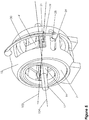
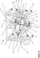
- a braking device 1 according to a first preferred embodiment of the invention comprises a body 2 in the form of a solid cylindrical wheel which is mounted coaxially on a rotation shaft 3 for rotation therewith about a first axis 101.
- the rotation shaft 3 is mounted within an inner cradle 4 by means of inner bearings 5.
- the inner cradle 4 is mounted for rotation about a second axis 102 within a middle cradle 6 by means of middle bearings 7.
- the middle cradle 6 is mounted for rotation about a fifth axis 105 within the outer cradle 8 by means of outer bearings 9, and the outer cradle 8, in turn, is mounted for rotation about a sixth axis 106 within a frame 10 by means of frame bearings 11.
- the type of the bearings in the braking device 1 may be fluid bearing type.
- the fluid may comprise liquid and/or gaseous fluids.
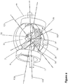
- the braking device 1 is used to brake a rotation that is desired to be braked about a fourth axis 104.
- the fourth axis 104 may be in any desired orientation,
- the second axis 102 is oriented with respect to the fourth axis 104 at a beta angle ⁇ .
- the first axis 101 is oriented with respect to the second axis 102 at an alpha angle ⁇ .
- the sixth axis 106 is substantially perpendicular to the fourth axis 104, and the fifth axis 105 is substantially perpendicular to the sixth axis 106.
- the third axis 103 is defined as the precession axis about which the precession of the body 2 occurs as a result of rotating the body 2 about the first axis 101 and applying torque to the body 2 about the second axis 102.
- the body 2 while the body 2 is being rotated about the first axis 101, if a torque is applied to the body 2 about the second axis 102, the body 2 starts precessing about the third axis 103, that is the first axis 101 starts rotating about the third axis 103.
- the third axis 103 is perpendicular to both the first axis 101 and the second axis 102.
- the first axis 101, the second axis 102, the third axis 103 and the fourth axis 104 substantially intersect at the centre of mass of the body 2.
- An example orientation of the axes can be seen in Figure 4 .
- the beta angle ⁇ values which are close to 0 degrees or 90 degrees may cause a reduction in the magnitude of the braking torque, therefore these values may not be preferred.
- the strength of the body 2 and the density distribution of the body 2 may affect the magnitude of the braking torque.
- the form of the body 2 may be different than solid cylindrical wheel.
- the body 2 may comprise a hub, a web and a rim of ring shape.
- the form of the body 2 may be such that the moment of inertia of the body 2 about the first axis 101 per unit mass is higher than or equal to (2/5) * R 2 where R is radius of the minimal bounding sphere of the body 2.
- the minimal bounding sphere is defined as the smallest sphere which contains the body 2.
- the body 2 may also be made from a material with a modulus of elasticity exceeding 70 GPa.
- the first axis 101 may be oriented with respect to the body 2 such that the moment of inertia of the body 2 about the first axis 101 is substantially maximised.
- the body 2 is rotated about the first axis 101 by means of pressurized fluid.
- the body 2 comprises one or more fluid pipes 12 mounted on the rotation shaft 3 directed radially outward from the centre of the rotation shaft 3.
- the braking device 1 comprises a fluid pump 14, and means (not shown) for conveying pressurized fluid to the pipes 12 mounted on the rotation shaft 3.
- the means (not shown) for conveying pressurized fluid to the pipes 12 may comprise one or more of: pipes; tubes, hoses, channels and rotary joints.
- the power required for the fluid pump 14 may be provided by an external power supply or by the rotation that is desired to be braked.
- the nozzles of the pipes 12 are oriented such that as the pressurized fluid exits from the nozzles, the reaction of the fluid applies torque to the body 2 so as to rotate the body 2 about the first axis 101.
- the nozzles are oriented in tangential direction to the body 2.
- the magnitude of the torque applied to the body 2 about the first axis 101 can be controlled by controlling the flow rate of the fluid.
- the body 2 may comprise another set of fluid pipes 13, the nozzles of which are oriented so as to apply torque to the body 2 about the first axis 101 in the opposite direction. In this case, conveying fluid to this set of pipes 13 causes deceleration of the body 2 about the first axis 101.
- a valve may be provided in order to alternate the fluid between the first set of pipes 12 and the second set of pipes 13.
- An example placement of the first set of pipes 12 and the second set of pipes 13 can be seen in Figure 4 .
- the arrows in Figure 4 indicate the flow direction of the fluid for this particular example.
- similarly formed channels may be provided inside the body 2.
- the braking device 1 comprises rotary connection means 16 which is used for connecting the rotation that is desired to be braked about the fourth axis 104 to the body 2 so as to transmit rotation and torque to the body 2 about the second axis 102.
- the rotary connection means 16 is rigidly coupled to a shaft 17 which is mounted for rotation about the fourth axis 104 by means of rotary connection means bearings 18.
- the shaft 17 of the rotary connection means 16 along the fourth axis 104 is engaged to the rotation that is desired to be braked about the fourth axis 104.
- the rotary connection means 16 is in the form of a ring. On the rotary connection means 16, there are two symmetrical slots 20 with respect to the fourth axis 104.
- the inner cradle 4 comprises two pins 21 in the form of a solid sphere which are oriented along the third axis 103. Each of these two pins 21 is supported by a sliding part 19 for spherical motion. Each sliding part 19 is arranged to slide inside one of the slots 20 on the rotary connection means 16. This arrangement allows the rotation of the inner cradle 4 about the third axis 103 with respect to the rotary connection means 16. The orientations of the slots 20 are determined such that the inner cradle 4 is allowed to rotate in a limited manner about an eighth axis 108 with respect to the rotary connection means 16.
- the eighth axis 108 is defined as the axis which is perpendicular to both the third axis 103 and the fourth axis 104 and passes through the centre of mass of the body 2.
- the size and the locations of the slots 20 are also determined such that a full rotation of the second axis 102 about the fourth axis 104 is allowed while the rotary connection means 16 is kept stationary. It is preferred that the magnitudes of the frictional forces between the sliding parts 19 and the corresponding slots 20, and between the pins 21 and the corresponding sliding parts 19 are as small as possible. With this arrangement, if the body 2 is initially stationary, a rotation of the rotary connection means 16 causes the body 2 to rotate about the second axis 102.
- the pins 21 may be mounted to the inner cradle 4 elastically so as to allow small movement of the pins 21 with respect to the inner cradle 4. This provides more balanced distribution of forces applied through these two pins 21, hence reducing the resultant force on the centre of the body 2.
- the braking device 1 may also comprise a clutch for disengaging the rotation that is desired to be braked from the rotary connection means 16 when braking torque is not needed.
- a transmission may be provided in order to change the ratio of the speed of the rotation that is desired to be braked to the speed of the rotation of the rotary connection means 16 about the fourth axis 104. In this case, the input shaft of the transmission is engaged to the rotation that is desired to be braked and the output shaft is engaged to the shaft 17 of the rotary connection means 16.
- the rotary connection means 16 connects the rotation that is desired to be braked about the fourth axis 104 to the body 2 so as to transmit rotation and torque to the body 2 about the second axis 102, the transmission also allows to change the speed of the rotation of the body 2 about the second axis 102 while the speed of the rotation that is desired to be braked is constant.
- the braking device 1 also comprises means for controlling the beta angle ⁇ .
- the means for controlling the beta angle ⁇ comprises an arm 22 which will be referred as the limiting arm 22.
- the limiting arm 22 comprises two rods which are rigidly coupled together such that the angle between the axis along which the first rod 23 is oriented and the axis along which the second rod 24 is oriented is at a desired value for the beta angle ⁇ .
- the limiting arm 22 is mounted to the braking device 1 such that the first rod 23 lies along the fourth axis 104 and supported for rotation about the fourth axis 104 by means of the first limiting arm bearings 25 of the frame 10; and the second rod 24 lies along the second axis 102 and supported for rotation about the second axis 102 by means of the second limiting arm bearings 26 of the inner cradle 4.
- This arrangement ensures that the motion of the second axis 102 is limited so as to keep the beta angle ⁇ constant at a selected value while allowing the second axis 102 to rotate about the fourth axis 104.
- the means for controlling the beta angle ⁇ may further comprise an actuator in order to adjust the beta angle ⁇ .
- the limiting arm 22 may comprise a hydraulic cylinder such that the barrel of the cylinder is jointly coupled to the first rod 23 and the piston rod of the cylinder is jointly coupled to the second rod 24. This arrangement allows controlling of the beta angle ⁇ by adjusting the length of the stroke of the piston rod.
- the braking device 1 preferably comprises sensors for measuring values of: the speed of the rotation of the body 2 about the first axis 101; the speed of the rotation of the rotary connection means 16; the beta angle ⁇ ; the speed of the rotation that is desired to be braked.
- the braking device 1 comprises an automatic control unit 27 (as can be seen in Figure 1 and Figure 2 for example) which is used to provide different operating conditions.
- the automatic control unit 27 gets different input signals from various sensors of the braking device 1 and sets the parameters of the device such as the speed of the rotation of the body 2 about the first axis 101, the magnitude of the braking torque, the beta angle ⁇ , and the ratio of the speed of the rotation that is desired to be braked to the speed of the rotation of the body 2 about the second axis 102.
- the automatic control unit 27 may also control the magnitude of the braking torque so as to keep the speed of the rotation that is desired to be braked substantially constant at a desired value (for instance, in order to keep the speed of a vehicle traveling downhill substantially constant at a desired value).
- the automatic control unit 27 controls the speed of the rotation of the body 2 about the first axis 101 and/or the speed of the rotation of the body 2 about the second axis 102.
- the speed of the rotation of the body 2 about the second axis 102 may be controlled by changing the ratio of the speed of the rotation that is desired to be braked to the speed of the rotation of the rotary connection means 16 about the fourth axis 104, that is by changing the speed ratio of the transmission.
- the automatic control unit 27 may also control the braking device 1 so as to remove the braking torque on the rotation that is desired to be braked when braking torque is not needed.
- the braking torque may be removed using at least one of: (i) stopping the rotation of the body 2 about the first axis 101, (ii) setting the beta angle ⁇ to 0 degrees or 90 degrees, (iii) disengaging the rotation that is desired to be braked from the rotary connection means 16.
- the braking torque may not be totally removed by setting the beta angle ⁇ to 0 degrees or 90 degrees because of the possible vibrations and deformations occurred in the braking device 1 which are caused by the internal forces.
- the normal line of the plane which contains the second axis 102 and the fourth axis 104 is defined as the line which is orthogonal to this plane and passes through the centre of mass of the body 2.
- the theta angle 6 is defined as the acute angle (or possibly the right angle) between the first axis 101 and the normal line of the plane which contains the second axis 102 and the fourth axis 104.
- the body 2 is first caused to rotate about the first axis 101 by means of conveying pressurized fluid obtained from the fluid pump 14 to the pipes 12 on the rotational shaft of the body 2.
- the rotary connection means 16 connects the rotation that is desired to be braked to the body 2 so as to transmit rotation and torque to the body 2 about the second axis 102.
- a torque is applied to the body 2 about the second axis 102 so as to rotate the body 2 about the second axis 102.
- the torque applied to the body 2 about the second axis 102 causes the body 2 to rotate about the second axis 102 such that the theta angle ⁇ becomes smaller than 90 degrees if it is not already so.
- the first axis 101 no more lies in the plane which contains the second axis 102 and the fourth axis 104.
- This enables the body 2 to have a limited freedom of rotation about the third axis 103 so that the body 2 is able to rotate about the third axis 103.
- the body 2 starts rotating about the third axis 103.
- this rotation is known as precession.
- the body 2 rotates about the first axis 101, the second axis 102 and the third axis 103 simultaneously.
- the rotation of the body 2 about the second axis 102 and the rotation of the body 2 about the third axis 103 are observed as if the body 2 rotates about the fourth axis 104.
- the body 2 is not rotated about the fourth axis 104; and the observed rotation of the body 2 about the fourth axis 104 is actually a result of the rotation of the body 2 about both the second axis 102 and the third axis 103.
- the braking torque about the second axis 102 is transmitted back to the rotation that is desired to be braked about the fourth axis 104 by means of the rotary connection means 16.
- the theta angle ⁇ remains constant at a value less than 90 degrees as long as the parameters of the braking device 1 are kept constant.
- the value of theta angle ⁇ depends on the parameters of the braking device 1. Therefore, the braking device 1 provides continuous braking torque against the rotation that is desired to be braked about the fourth axis 104.
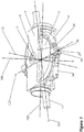
- the outer cradle 8 is not used and the middle cradle 6 is mounted for spherical motion within the frame 10 by means of fluid bearings.
- the rotation of the middle cradle 6 about the second axis 102 should be prevented while allowing the rotation of the second axis 102 about the fourth axis 104.
- a linear guidance slot 29 is provided on the frame 10.
- the guidance pin 28 is located inside this guidance slot 29,
- the guidance arm 30 preferably comprises some elastic material so as to dampen possible vibrations.
- the form and the location of the guidance pin 28, the guidance arm 30 and the guidance slot 29 can be different than the ones shown in Figure 5 as long as the rotation of the middle cradle 6 about the second axis 102 is prevented while allowing the rotation of the second axis 102 about the fourth axis 104.
- Figure 5 is provided for illustrating the parts which are specific for this embodiment.
- the motion of the guidance pin 28 may also be constrained by means of the guidance slot 29 only.
- the guidance pin 28 may be supported for rotation by a sliding part for spherical motion.
- the sliding part may be arranged to slide inside the guidance slot 29. It is preferred that the magnitudes of the frictional forces between the sliding part and the slot 29, and between the guidance pin 28 and the sliding part are as small as possible.
- the above mentioned guidance mechanism may not be needed. In this case the rotation of the middle cradle 6 about the second axis 102 is prevented by means of frictional forces. However, this may not be reliable, thus it may be preferred to use the above mentioned guidance mechanism.
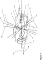
- an innermost cradle 31 is provided as illustrated in Figure 6 .
- the rotation shaft 3 of body 2 is mounted for rotation about the first axis 101 within the innermost cradle 31 by means of innermost bearings 32.
- the innermost cradle 31, in turn, is mounted for rotation about a seventh axis 107 within the inner cradle 4 by means of, for instance, a track roller guidance system or a fluid bearing.
- the seventh axis 107 is an axis such that the rotation of the innermost cradle 31 about the seventh axis 107 causes a change in the alpha angle ⁇ .
- the seventh axis 107 is preferably same as the third axis 103.
- the braking device 1 also comprises an actuator 33 for rotating the innermost cradle 31 about the seventh axis 107 within the inner cradle 4.
- the actuator 33 could be for instance a motor or a hydraulic cylinder or a pneumatic cylinder.
- the alpha angle ⁇ can be adjusted by controlling the actuator 33. Therefore, in this embodiment, the magnitude of the braking torque can be adjusted by adjusting the alpha angle ⁇ .
- the automatic control unit 27 may set both the alpha angle ⁇ and the beta angle ⁇ to 0 degrees which causes a reduction in the magnitudes of the internal forces which occur inside the braking device 1 when braking torque is not needed. Note that Figure 6 is provided for illustrating the parts which are specific for this embodiment.
- a preferred embodiment of the means for reducing the effect of frictional forces that occur on the contact surfaces of the rotary connection means 16 and the structure through which the rotary connection means 16 applies torque to the body 2 comprises two identical structures which are mounted symmetrically with respect to the fourth axis 104.
- Each structure comprises a cylinder 34 and a housing 35 wherein the barrel of the cylinder 34 is jointly mounted to the rotary connection means 16 and the piston rod of the cylinder 34 is jointly mounted to the housing 35.
- the cylinders 34 can be hydraulic or pneumatic. Instead of cylinders 34, another kind of actuators may also be used.
- Each of the housings 35 is structured to slide inside one of the slots 20 of the rotary connection means 16 and also supports one of the spherical pins 21 of the inner cradle 4 for spherical motion.
- extending one of the cylinders 34 and retracting the other cylinder 34 causes the inner cradle 4 to rotate about the eighth axis 108.
- Rotation of the inner cradle 4 about the eighth axis 108 causes a change in the theta angle ⁇ .
- the stroke length of the cylinders 34 the theta angle ⁇ can be adjusted.
- theta angle ⁇ remains constant at a value which is less than 90 degrees as long as the parameters of the braking device 1 are kept constant.
- the frictional forces between the sliding parts 19 connected to the pins 21 of the inner cradle 4 (or specifically the housings 35 in this particular embodiment) and the corresponding slots 20 of the rotary connection means 16 may prevent the body 2 from taking a position with a smaller theta angle ⁇ value. This may cause a reduction in the magnitude of the braking torque.
- the inner cradle 4 may be rotated about the eighth axis 108 so as to bring the body 2 to a position with a desired theta angle ⁇ value which is smaller than the previous value.
- the rotation of the inner cradle 4 about the eighth axis 108 in the direction so as to decrease the theta angle ⁇ should not be prevented.
- the cylinders 34 may be controlled so as to prevent the rotation of the inner cradle 4 about the eighth axis 108 in the direction so as to increase the theta angle ⁇ at the desired theta angle ⁇ value.
- the size and the locations of the slots 20 of the rotary connection means 16 can be determined such that the rotation of the inner cradle 4 about the eighth axis 108 in the direction so as to increase the theta angle ⁇ is prevented at the desired theta angle ⁇ value.
- This may also be achieved by means of a mechanical abutment placed on the rotary connection means 16 restricting the motion of the at least one of the sliding parts 19 connected to the pins 21 of the inner cradle 4 inside the corresponding slots 20 of the rotary connection means 16. It is found that the smaller theta angle ⁇ values may provide an increase in the magnitude of the braking torque and also a reduction in the amount of vibrations occurred in the braking device 1.
- a preferred embodiment of the means for distributing forces between the two force application points of the rotary connection means 16 so as to reduce the resultant force on the centre of mass of the body 2 comprises two identical cylinders 36.
- Each cylinder 36 is mounted to one of the housings 35 such that the barrel of the cylinder 36 is rigidly mounted to the inner surface of the housing 35 and the piston rod of the cylinder 36 preferably with a spherical surface is in contact with the spherical pin 21 of the inner cradle 4 such that the pin 21 is supported for spherical motion.
- the bottom chambers of the two cylinders 36 are interconnected in a closed loop wherein the forces applied by the two cylinders 36 are equal. This mechanism ensures that the magnitudes of the forces applied by the rotary connection means 16 to the two pins 21 of the inner cradle 4 are substantially equal. This provides a reduction in the magnitude of the resultant force on the centre of mass of the body 2.
- the orientations of the two slots 20 of the rotary connection means 16 are rotated about a ninth axis 109 by a gamma angle ⁇ .
- the ninth axis 109 is defined as the axis which is perpendicular to both the fourth axis 104 and the eighth axis 108 and passes through the centre of mass of the body 2.
- the inner cradle 4 is allowed to rotate in a limited manner with respect to the rotary connection means 16 about an eleventh axis 111 instead of the eighth axis 108.
- the eleventh axis 111 is the axis which is formed by rotating the eighth axis 108 about the ninth axis 109 by the gamma angle ⁇ .
- the direction of the rotation of the orientations of the slots 20 is preferably determined such that the rotary connection means 16 further causes a decrease in the theta angle ⁇ .
- the magnitude of this effect may be changed by changing the value of the gamma angle ⁇ .
- the stator part of the source of motive power 37 is rigidly coupled to the middle cradle 6 and the rotor part of the source of motive power 37 is rigidly coupled to the inner cradle 4.
- the rotation of the stator part of the source of motive power 37 about the second axis 102 is prevented.
- the source of motive power 37 applies torque to the body 2 about the second axis 102 through the inner cradle 4.
- the source of motive power 37 may be for instance an electrical motor or a hydraulic motor or a pneumatic motor.
- the power required for the source of motive power 37 is provided by the rotation that is desired to be braked.
- an electricity generator or a fluid pump which is engaged to the rotation that is desired to be braked is provided.
- the power obtained from the electricity generator or the fluid pump can be transferred to the source of motive power 37 by means of electrical wires or fluid conveying means such as hoses, tubes and pipes, and a rotary joint which is mounted for rotation about the fourth axis 104 within the frame 10.
- the braking device 1 comprises a body 2 with a set of blades 38, a set of two nozzles 39 attached to the inner cradle 4, a fluid pump 14, and means (not shown) for conveying pressurized fluid to nozzles attached to the inner cradle 4.
- the orientations of the two nozzles 39 and the form of the blades 38 are determined such that when the pressurized fluid is projected on the blades 38 of the body 2, the fluid causes a torque to be applied to the body 2 about the first axis 101 so as to accelerate the body 2 about the first axis 101.
- the magnitude of the torque applied to the body 2 about the first axis 101 can be controlled by controlling the flow rate of the fluid.
- a second set of nozzles (not shown in Figure 11 ) may also be provided so as to apply torque to the body 2 about the first axis 101 in the opposite direction, that is so as to decelerate the body 2 about the first axis 101.
- a valve may be provided in order to alternate the fluid between the first and the second set of nozzles.
- the fixed outer gear 40 is rigidly coupled to the middle cradle 6 and in mesh with the inner gear 41.
- the inner gear 41 is engaged to the input shaft of the transmission 42.
- the first bevel gear 43 is engaged to the output shaft of the transmission 42.
- the second bevel gear 44 is engaged to the rotation shaft 3 of the body 2, and also in mesh with the first bevel gear 43.
- This mechanism engages the rotation of the body 2 about the second axis 102 to the rotation of the body 2 about the first axis 101 such that when the body 2 is rotated about the second axis 102, the body 2 also rotates about the first axis 101.
- the transmission 42 is used to change the ratio of the speed of the rotation of the body 2 about the second axis 102 to the speed of the rotation of the body 2 about the first axis 101.
- the transmission 42 may have a fixed speed ratio or variable speed ratio.
- the speed ratio of the transmission 42 may be controlled by the automatic control unit 27 so as to change the speed of the rotation of the body 2 about the first axis 101.
- a source of motive power is provided so as to rotate the body 2 about the first axis 101.
- the source of motive power could be for instance an electrical motor or a hydraulic motor or a pneumatic motor.
- the power required for the source of motive power may be provided by an external power supply or by the rotation that is desired to be braked.
- At least one of the first, second, third or fourth axes do not pass through the centre of mass of the body 2.
- an embodiment of an assembly 45 of braking devices 1 comprises four identical braking devices 1 arranged in a 2 x 2 array.
- the frames 10 of the braking devices 1 are rigidly coupled together such as the fourth axes 104 of the braking devices 1 are substantially parallel to each other.
- the assembly 45 further comprises a means 46 for distributing a rotation about a tenth axis 110 to each braking device 1 such that the shaft 47 of the means 46 for distributing a rotation is engaged to the shaft 17 of the rotary connection means 16 of each braking device 1 so as to cause the rotary connection means 16 of each braking device 1 to rotate at the same rotational speed but at different respective phase angle.
- the tenth axis 110 is could be any axis which is substantially parallel to the fourth axes 104 of the braking devices 1.
- the rotation that is desired to be braked is engaged to the shaft 47 of the means 46 for distributing a rotation.
- the means 46 for distributing a rotation may comprise one or more chain-sprocket mechanisms, belt-pulley mechanisms or gear mechanisms.
- the phase angles in this embodiment are equally spaced in order to reduce the magnitude of the internal resultant torque. For instance, if the phase angle of the upper left braking device 1 is assumed to be 0 degrees, the phase angle of the lower left braking device would be 90 degrees, the phase angle of the lower right braking device would be 180 degrees, and the phase angle of the upper right braking device would be 270 degrees.
- the relative orientations of the bodies 2 of the braking devices 1 at a specific instant are illustrated in Figure 14 .
- the means 46 for distributing a rotation ensures that the rotations of the rotary connection means 16 of braking devices 1 are synchronized so as to preserve the relative orientations of the bodies 2 of the braking devices 1. This arrangement reduces the vibrations occurred in the assembly 45.
- the magnitude of the braking torque provided by the assembly 45 is the sum of the braking torques provided by each of the braking devices 1 in the assembly 45.
Landscapes
- Engineering & Computer Science (AREA)
- Mechanical Engineering (AREA)
- Transportation (AREA)
- General Engineering & Computer Science (AREA)
- Physics & Mathematics (AREA)
- Fluid Mechanics (AREA)
- Chemical & Material Sciences (AREA)
- Combustion & Propulsion (AREA)
- General Physics & Mathematics (AREA)
- Radar, Positioning & Navigation (AREA)
- Remote Sensing (AREA)
- Braking Arrangements (AREA)
Claims (50)
- Un dispositif de freinage (1) comprenant :un corps (2) monté pour tourner autour d'un premier axe (101) ;des moyens (12, 13, 14, 38, 39, 40, 41, 42, 43, 44) pour faire tourner le corps (2) autour du premier axe (101) ;caractérisé en ce que :le dispositif de freinage (1) comprend un deuxième axe (102), un troisième axe (103) et un quatrième axe (104), le dispositif de freinage (1) étant configuré pour permettre au corps (2) de tourner en autre autour du deuxième axe (102) et du troisième axe (103), le premier axe (101) étant orienté par rapport au deuxième axe (102) à un angle alpha (α) qui est supérieur à 0 degré, le deuxième axe (102) étant orienté par rapport au quatrième axe (104) à un angle beta (β) qui est supérieur à 0 degré et inférieur à 90 degrés, le troisième axe (103) étant l'axe de précession autour duquel la précession du corps (2) a lieu suite à la rotation du corps (2) autour du premier axe (101) et appliquant le couple sur le corps (2) autour du deuxième axe (102), dans lequel le deuxième axe (102) est permis de tourner autour du quatrième axe (104) indépendamment de la rotation du corps (2) autour du deuxième axe (102), et le corps (2) est permis de tourner autour du deuxième axe (102) indépendamment de la rotation du deuxième axe (102) autour du quatrième axe (104) ;le dispositif de freinage (1) comprend en outre :des moyens (16, 37) pour raccorder une rotation que l'on souhaite freiner autour du quatrième axe (104) au corps (2) afin de transmettre la rotation et le couple au corps (2) autour du deuxième axe (102) ;dans lequel la rotation du corps (2) autour du premier axe (101) et le couple appliqué sur le corps (2) autour du deuxième axe (102) provoquent ensemble le corps (2) à tourner en autre autour du troisième axe (103), le corps (2) tourne autour du premier axe (101), du deuxième axe (102) et du troisième axe (103) simultanément, la rotation du corps (2) autour du premier axe (101) et la rotation du corps (2) autour du troisième axe (103) provoquent ensemble l'occurrence d'un couple de freinage autour du deuxième axe (102) ;pour obtenir ainsi le couple de freinage contre la rotation que l'on souhaite freiner autour du quatrième axe (104).
- Le dispositif de freinage (1) selon la revendication 1, comprenant en outre un berceau interne (4), un berceau intermédiaire (6) et un bâti (10).
- Le dispositif de freinage (1) selon la revendication 2, comprenant en outre un berceau externe (8) dans lequel le corps (2) est monté pour tourner autour du premier axe (101) à l'intérieur du berceau interne (4), le berceau interne (4) est monté pour tourner autour du deuxième axe (102) à l'intérieur du berceau intermédiaire (6), le berceau intermédiaire (6) est monté pour tourner autour d'un cinquième axe (105) à l'intérieur du berceau externe (8), et le berceau externe (8) est monté pour tourner autour d'un sixième axe (106) à l'intérieur du le bâti (10).
- Le dispositif de freinage (1) selon la revendication 2, comprenant en outre des moyens (28, 29, 30) pour empêcher la rotation du berceau intermédiaire (6) autour du deuxième axe (102), dans lequel le corps (2) est monté pour tourner autour du premier axe (101) à l'intérieur du berceau interne (4), le berceau interne (4) est monté pour tourner autour du deuxième axe (102) à l'intérieur du berceau intermédiaire (6), le berceau intermédiaire (6) est monté pour le mouvement sphérique à l'intérieur du bâti (10) et la rotation du berceau intermédiaire (6) autour du deuxième axe (102) est empêchée.
- Le dispositif de freinage (1) selon la revendication 4, comprenant en outre des moyens de palier fluide qui supportent le berceau intermédiaire (6) pour le mouvement sphérique dans le bâti (10).
- Le dispositif de freinage (1) selon l'une quelconque des revendications 2 à 5, comprenant en outre le berceau situé le plus à l'intérieur (31), dans lequel le corps (2) est monté pour tourner autour du premier axe (101) dans le berceau situé le plus à l'intérieur (31), le berceau situé le plus à l'intérieur (31) est monté pour tourner autour d'un septième axe (107) dans le berceau interne (4) et la rotation du berceau situé le plus à l'intérieur (31) autour du septième axe (107) provoque un changement d'angle alpha (α).
- Le dispositif de freinage (1) selon l'une quelconque des revendications 1 à 6, comprenant en outre des moyens de palier de fluide afin de supporter un ou plusieurs éléments parmi : le corps (2), le berceau situé le plus à l'intérieur (31), le berceau interne (4), le berceau intermédiaire (6) et le berceau externe (8).
- Le dispositif de freinage (1) selon l'une quelconque des revendications 1 à 7, comprenant en outre des moyens pour contrôler l'angle alpha (α).
- Le dispositif de freinage (1) selon la revendication 8, dans lequel les moyens pour contrôler l'angle alpha (α) comprend des moyens (33) pour faire tourner le berceau situé le plus à l'intérieur (31) autour du septième axe (107).
- Le dispositif de freinage (1) selon l'une quelconque des revendications 1 à 9, comprenant en outre des moyens pour contrôler l'angle beta (β).
- Le dispositif de freinage (1) selon la revendication 10, dans lequel le moyen pour contrôler l'angle beta (β) comprend des moyens (22) pour limiter le mouvement du deuxième axe (102) de sorte que l'angle beta (β) est constant à une valeur sélectionnée, et le deuxième axe (102) est permis de tourner autour du quatrième axe (104).
- Le dispositif de freinage (1) selon la revendication 11, dans lequel les moyens (22) pour limiter le mouvement du deuxième axe (102) comprend les moyens d'actionneur afin d'ajuster l'angle beta (β).
- Le dispositif de freinage (1) selon l'une quelconque des revendications 1 à 12, dans lequel les moyens pour raccorder une rotation que l'on souhaite freiner autour du quatrième axe (104) au corps (2) afin de transmettre la rotation et le couple au corps (2) autour du deuxième axe (102) comprennent des moyens de raccordement rotatif (16), les moyens de raccordement rotatif (16) étant montés pour tourner autour du quatrième axe (104), les moyens de raccordement rotatif (16) étant mis en prise avec la rotation que l'on souhaite freiner autour du quatrième axe (104), et les moyens de raccordement rotatif (16) étant structurés afin d'appliquer le couple sur le corps (2) autour du deuxième axe (102) lorsque les moyens de raccordement rotatif (16) tourne autour du quatrième axe (104).
- Le dispositif de freinage (1) selon la revendication 13, dans lequel les moyens de raccordement rotatif (16) comprennent des moyens pour réduire l'effet des forces de friction qui se produisent sur les surfaces de contact des moyens de raccordement rotatif (16) et la structure par le biais de laquelle les moyens de raccordement rotatif (16) appliquent le couple sur le corps (2).
- Un dispositif de freinage (1) selon la revendication 14, dans lequel les moyens pour réduire l'effet des forces de friction comprennent un ou plusieurs actionneurs (34) qui sont montés sur les moyens de raccordement rotatif (16) et agencés pour appliquer une force sur la structure à travers laquelle les moyens de raccordement rotatif (16) appliquent le couple sur le corps (2) afin de réduire l'effet des forces de friction.
- Un dispositif de freinage (1) selon l'une quelconque des revendications 13 à 15, dans lequel les moyens de raccordement rotatif (16) comprennent de moyens pour répartir la force entre les deux points d'application de force du moyen de raccordement rotatif (16) afin de réduire la grandeur de la force résultante sur le centre de masse du corps (2).
- Un dispositif de freinage (1) selon la revendication 16, dans lequel les moyens pour répartir la force entre les deux points d'application de force du moyen de raccordement rotatif (16) comprennent deux cylindres (36), les cylindres (36) sont montés sur les moyens de raccordement rotatif (16) afin d'appliquer la force sur la structure à travers laquelle les moyens de raccordement rotatif (16) appliquent le couple sur le corps (2), les chambres inférieures des cylindres (36) sont interconnectées dans une boucle fermée, et les forces appliquées par les deux cylindres (36) sont égales.
- Un dispositif de freinage (1) selon l'une quelconque des revendications 13 à 17, dans lequel la structure à travers laquelle les moyens de raccordement rotatif (16) appliquent le couple sur le corps (2) est le berceau interne (4) ou le berceau situé le plus à l'intérieur (31).
- Un dispositif de freinage (1) selon l'une quelconque des revendications 2 à 18, dans lequel les moyens pour raccorder une rotation que l'on souhaite freiner autour du quatrième axe (104) au corps (2) afin de transmettre la rotation et le couple au corps (2) autour du deuxième axe (102) comprennent une source d'énergie motrice (37), dans lequel la partie de stator de la source d'énergie motrice (37) est rigidement couplée au berceau intermédiaire (6) et la partie de rotor de la source d'énergie motrice (37) est rigidement couplée au berceau interne (4), l'énergie nécessaire pour la source d'énergie motrice (37) est fournie par la rotation que l'on souhaite freiner, dans lequel la rotation de la partie de stator de la source d'énergie motrice (37) autour du deuxième axe (102) est empêchée, et la source d'énergie motrice (37) applique le couple sur le corps (2) autour du deuxième axe (102).
- Un dispositif de freinage (1) selon l'une quelconque des revendications 1 à 19, comprenant en outre des moyens pour contrôler le rapport de la vitesse de rotation que l'on souhaite freiner sur la vitesse de la rotation du corps (2) autour du deuxième axe (102).
- Un dispositif de freinage (1) selon la revendication 20, dans lequel les moyens pour contrôler le rapport de la vitesse de la rotation que l'on souhaite freiner sur la vitesse de la rotation du corps (2) autour du deuxième axe (102) comprennent les moyens de transmission de sorte que la rotation que l'on souhaite freiner est mise en prise avec l'arbre d'entrée des moyens de transmission, et les moyens pour raccorder une rotation que l'on souhaite freiner autour du quatrième axe (104) au corps (2) afin de transmettre la rotation et le couple au corps (2) autour du deuxième axe (102) sont mis en prise avec l'arbre de sortie des moyens de transmission.
- Un dispositif de freinage (1) selon l'une quelconque des revendications 1 à 21, dans lequel les moyens pour faire tourner le corps (2) autour du premier axe (101) comprennent un ou plusieurs éléments parmi : un moteur électrique ; un moteur hydraulique ; et un moteur pneumatique.
- Un dispositif de freinage (1) selon l'une quelconque des revendications 1 à 22, dans lequel le corps (2) comprend une ou plusieurs pales (38).
- Un dispositif de freinage (1) selon la revendication 23, dans lequel les moyens pour faire tourner le corps (2) autour du premier axe (101) comprennent des moyens (14) pour pomper le fluide, et des moyens (39) pour projeter du fluide sur les pales (38) du corps (2) afin de faire tourner le corps (2) autour du premier axe (101).
- Un dispositif de freinage (1) selon l'une quelconque des revendications 1 à 24, dans lequel le corps (2) comprend un ou plusieurs tuyaux ou canaux de fluide (12, 13).
- Un dispositif de freinage (1) selon la revendication 25, dans lequel les moyens pour faire tourner le corps (2) autour du premier axe (101) comprennent des moyens (14) pour pomper le fluide dans un ou plusieurs tuyaux (12, 13) ou canaux de fluide du corps (2) de sorte que le fluide sort des buses des tuyaux (12, 13) ou canaux, le corps (2) tourne autour du premier axe (101) suite à la réaction du fluide.
- Un dispositif de freinage (1) selon l'une quelconque des revendications 1 à 26, dans lequel l'énergie requise pour les moyens (12, 13, 14, 38, 39, 40, 41, 42, 43, 44) pour faire tourner le corps (2) autour du premier axe (101), est fournie par la rotation que l'on souhaite freiner.
- Un dispositif de freinage (1) selon l'une quelconque des revendications 1 à 27, comprenant en outre des moyens (27) pour contrôler les moyens pour faire tourner le corps (2) autour du premier axe (101) afin de contrôler la vitesse de la rotation du corps (2) autour du premier axe (101).
- Un dispositif de freinage (1) selon l'une quelconque des revendications 1 à 21, dans lequel les moyens pour faire tourner le corps (2) autour du premier axe (101) comprennent des moyens de mise en prise mécanique (40, 41, 42, 43, 44) pour mettre en prise la rotation du corps (2) autour du deuxième axe (102) avec la rotation du corps (2) autour du premier axe (101) dans lequel lorsque le corps (2) tourne autour du deuxième axe (102), le corps (2) tourne également autour du premier axe (101).
- Un dispositif de freinage (1) selon la revendication 29, dans lequel les moyens de mise en prise mécanique comprennent des moyens de transmission (42) afin de modifier la vitesse de rotation du corps (2) autour du premier axe (101).
- Un dispositif de freinage (1) selon l'une quelconque des revendications 1 à 30, comprenant en outre un ou plusieurs capteurs pour mesurer les valeurs d'un ou de plusieurs des paramètres suivants : la vitesse de la rotation du corps (2) autour du premier axe (101); la vitesse de la rotation des moyens pour raccorder une rotation que l'on souhaite freiner autour du quatrième axe (104) au corps (2) afin de transmettre la rotation et le couple au corps (2) autour du deuxième axe (102) ; l'angle alpha (α) ; l'angle beta (β) ; la grandeur du couple de freinage ; la vitesse de la rotation que l'on souhaite freiner.
- Un dispositif de freinage (1) selon l'une quelconque des revendications 1 à 31, comprenant en outre un organe de commande avec une unité de commande automatique (27) qui commande un ou plusieurs des éléments suivants : la vitesse de la rotation du corps (2) autour du premier axe (101) ; l'angle alpha (α) ; l'angle beta (β) ; et le rapport de la vitesse de rotation que l'on souhaite freiner sur la vitesse de la rotation du corps (2) autour du deuxième axe (102).
- Un dispositif de freinage (1) selon l'une quelconque des revendications 1 à 32, comprenant en outre des moyens pour contrôler la grandeur du couple de freinage.
- Un dispositif de freinage (1) selon la revendication 33, dans lequel la grandeur du couple de freinage est contrôlée en contrôlant un ou plusieurs des éléments suivants : la vitesse de la rotation du corps (2) autour du premier axe (101) ; l'angle alpha (α) ; et le rapport de la vitesse de la rotation que l'on souhaite freiner sur la vitesse de la rotation du corps (2) autour du deuxième axe (102).
- Un dispositif de freinage (1) selon l'une quelconque des revendications 1 à 34, comprenant en outre des moyens pour déplacer le corps (2) vers une position dans laquelle le premier axe (101) et le quatrième axe (104) sont parallèles ou coïncident lorsque le couple de freinage n'est pas nécessaire, dans lequel les grandeurs des forces internes qui se produisent à l'intérieur du dispositif de freinage (1) sont réduites.
- Un dispositif de freinage (1) selon l'une quelconque des revendications 1 à 35, dans lequel l'angle alpha (α) est de 90 degrés.
- Un dispositif de freinage (1) selon l'une quelconque des revendications 1 à 36, dans lequel le centre de masse du corps (2) est sur le quatrième axe (104).
- Un dispositif de freinage (1) selon l'une quelconque des revendications 1 à 37, dans lequel le premier axe (101), le deuxième axe (102), le troisième axe (103) et le quatrième axe (104) se coupent au centre de masse du corps (2).
- Un dispositif de freinage (1) selon l'une quelconque des revendications 1 à 38, dans lequel chacun parmi le premier axe (101), le deuxième axe (102) et le troisième axe (103) sont perpendiculaires aux deux autres axes.
- Un dispositif de freinage (1) selon l'une quelconque des revendications 1 à 39, dans lequel le dispositif de freinage (1) fournit un couple de freinage continu de préférence constant contre la rotation que l'on souhaite freiner autour du quatrième axe (104).
- Un ensemble (45) de deux dispositifs de freinage ou plus, dont chacun comprend un dispositif de freinage (1) selon l'une quelconque des revendications 1 à 40, en combinaison avec les moyens (46) pour répartir la rotation que l'on souhaite freiner sur chaque dispositif de freinage (1) afin de faire tourner chacun des moyens (16) pour le raccordement d'une rotation que l'on souhaite freiner autour du quatrième axe (104) au corps (2) afin de transmettre la rotation et le couple au corps (2) autour du deuxième axe (102) à la même vitesse de rotation mais à des angles de phase respectifs différents, dans lequel les grandeurs des forces déséquilibrées dans l'ensemble (45) sont réduites, dans lequel les vibrations qui se produisent dans l'ensemble (45) sont réduites et la grandeur du couple de freinage fourni par l'ensemble (45) est la somme des couples de freinage fournis par chacun des dispositifs de freinage dans l'ensemble (45).
- Une méthode pour générer un couple de freinage dans un dispositif de freinage (1) comprenant un premier axe (101), un deuxième axe (102) et un troisième axe (103), la méthode comprenant :monter un corps (2) pour tourner autour du premier axe (101), du deuxième axe (102) et du troisième axe (103) ;faire tourner le corps (2) autour du premier axe (101) ;caractérisé en ce que :le dispositif de freinage comprend en outre un quatrième axe (104), le premier axe (101) étant orienté par rapport au deuxième axe (102) à un angle alpha (α) qui est supérieur à 0 degré, le deuxième axe (102) étant orienté par rapport au quatrième axe (104) à un angle beta (β) qui est supérieur à 0 degré et inférieur à 90 degrés, le troisième axe (103) étant l'axe de précession autour duquel la précession du corps (2) se produit suite à la rotation du corps (2) autour du premier axe (101) et appliquant le couple sur le corps (2) autour du deuxième axe (102), dans lequel le deuxième axe (102) est permis de tourner autour du quatrième axe (104) indépendamment de la rotation du corps (2) autour du deuxième axe (102), et le corps (2) est permis de tourner autour du deuxième axe (102) indépendamment de la rotation du deuxième axe (102) autour du quatrième axe (104) ;la méthode comprend en outre l'étape deraccorder une rotation que l'on souhaite freiner au quatrième axe (104) afin de transmettre la rotation et le couple au corps (2) autour du deuxième axe (102) ;dans laquelle la rotation du corps (2) autour du premier axe (101) et le couple appliqué sur le corps (2) autour du deuxième axe (102) provoquent ensemble le corps (2) à tourner en autre autour du troisième axe (103), le corps (2) tourne autour du premier axe (101), du deuxième axe (102) et du troisième axe (103) simultanément, cependant la rotation du corps (2) autour du deuxième axe (102) et la rotation du corps (2) autour du troisième axe (103) sont observées comme si le corps (2) tournait autour du quatrième axe (104), la rotation du corps (2) autour du premier axe(101) et la rotation du corps (2) autour du troisième axe (103) provoquent ensemble un couple de freinage à se produire autour du deuxième axe (102) ;pour obtenir ainsi le couple de freinage contre la rotation que l'on souhaite freiner autour du quatrième axe (104).
- Une méthode selon la revendication 42, comprenant en outre l'étape consistant à ajuster la grandeur du couple de freinage.
- Une méthode selon la revendication 43, dans laquelle l'étape consistant à ajuster la grandeur du couple de freinage comprend l'étape consistant à ajuster un ou plusieurs des éléments suivants : la vitesse de la rotation du corps (2) autour du premier axe (101) ; l'angle alpha (α) ; et le rapport de la vitesse de la rotation que l'on souhaite freiner sur la vitesse de la rotation du corps (2) autour du deuxième axe (102).
- Une méthode selon l'une quelconque des revendications 42 à 44, comprenant en outre l'étape consistant à supprimer le couple de freinage lorsque le couple de freinage n'est pas nécessaire.
- Une méthode selon la revendication 45, dans laquelle l'étape consistant à supprimer le couple de freinage comprend l'étape consistant à déplacer le corps (2) vers une position dans laquelle le premier axe (101) et le quatrième axe (104) sont parallèles ou coïncident.
- Une méthode selon l'une quelconque des revendications 45 ou 46, dans laquelle l'étape consistant à supprimer le couple de freinage comprend l'étape consistant à déconnecter la rotation que l'on souhaite freiner du corps (2).
- Une méthode selon l'une quelconque des revendications 45 à 47, dans laquelle l'étape consistant à supprimer le couple de freinage comprend l'étape consistant à ajuster l'angle alpha (α) et/ou l'angle beta (β) à 0 degré.
- Une méthode selon l'une quelconque des revendications 45 à 48, dans laquelle l'étape consistant à supprimer le couple de freinage comprend l'étape consistant à arrêter la rotation du corps (2) autour du premier axe (101).
- Une méthode selon l'une quelconque des revendications 42 à 49, dans laquelle un couple de freinage continu, de préférence constant est fourni contre la rotation que l'on souhaite freiner autour du quatrième axe (104).
Applications Claiming Priority (1)
| Application Number | Priority Date | Filing Date | Title |
|---|---|---|---|
| PCT/EP2016/067256 WO2018014947A1 (fr) | 2016-07-20 | 2016-07-20 | Dispositif à frein gyroscopique et procédé associé |
Publications (2)
| Publication Number | Publication Date |
|---|---|
| EP3487731A1 EP3487731A1 (fr) | 2019-05-29 |
| EP3487731B1 true EP3487731B1 (fr) | 2020-03-18 |
Family
ID=56683891
Family Applications (1)
| Application Number | Title | Priority Date | Filing Date |
|---|---|---|---|
| EP16750637.7A Active EP3487731B1 (fr) | 2016-07-20 | 2016-07-20 | Frein gyroscopique et procede de freinage avec un gyroscope |
Country Status (16)
| Country | Link |
|---|---|
| US (1) | US10935091B2 (fr) |
| EP (1) | EP3487731B1 (fr) |
| JP (2) | JP2019522588A (fr) |
| KR (1) | KR102610334B1 (fr) |
| CN (1) | CN109311455B (fr) |
| AR (1) | AR109089A1 (fr) |
| CA (1) | CA3030776C (fr) |
| EA (1) | EA036123B1 (fr) |
| ES (1) | ES2798623T3 (fr) |
| IL (1) | IL263019B (fr) |
| JO (1) | JOP20170156B1 (fr) |
| MA (1) | MA45698B1 (fr) |
| MX (1) | MX386074B (fr) |
| TW (1) | TW201803753A (fr) |
| UY (1) | UY37330A (fr) |
| WO (1) | WO2018014947A1 (fr) |
Families Citing this family (2)
| Publication number | Priority date | Publication date | Assignee | Title |
|---|---|---|---|---|
| AU2017420133A1 (en) * | 2017-06-21 | 2020-02-06 | Erke Erke Arastirmalari Ve Mühendislik A.S. | Braking device and method |
| JP2023047495A (ja) | 2021-09-27 | 2023-04-06 | キヤノン株式会社 | 移動体、画像処理方法、およびコンピュータプログラム |
Family Cites Families (17)
| Publication number | Priority date | Publication date | Assignee | Title |
|---|---|---|---|---|
| US2246738A (en) * | 1941-06-24 | Means fob mounting gyros | ||
| US3353413A (en) * | 1967-11-21 | Gyroscope flexible leads | ||
| US2278913A (en) * | 1939-12-20 | 1942-04-07 | Sperry Gyroscope Co Inc | Automatic brake for gyroscopic instruments |
| US2797580A (en) * | 1955-07-18 | 1957-07-02 | Bosch Arma Corp | Gyroscope suspension |
| DE3016381A1 (de) * | 1979-01-17 | 1981-11-05 | Christian Dipl.-Ing. 8900 Augsburg Strobel | Aktives medienfreies traegruder |
| US5437420A (en) * | 1993-07-16 | 1995-08-01 | Hughes Aircraft Company | High torque double gimbal control moment gyro |
| NL1019065C1 (nl) * | 2001-09-28 | 2003-03-31 | Johannes Antonius Josephu Gend | Continue rem gebaseerd op het gyroscopisch effect. |
| DE10324771A1 (de) * | 2003-05-31 | 2004-12-16 | Bpw Bergische Achsen Kg | Anordnung einer Bremsscheibe an einer Radnabe |
| CN2748347Y (zh) * | 2004-09-16 | 2005-12-28 | 王焕光 | 将制动摩擦力转换为前进动力的刹车装置 |
| US7296663B2 (en) * | 2005-02-24 | 2007-11-20 | Mario Joseph Spina | Automotive wheel anti-gyro |
| TR200605622A2 (tr) * | 2006-10-10 | 2008-05-21 | Erke Erke Ara�Tirmalari Ve M�Hend�Sl�K Anon�M ��Rket� | Erke üreten bir kuvvet makinesi ve bunun çalışma yöntemi |
| TR200705658A2 (tr) * | 2007-08-16 | 2009-03-23 | mevcut% %dosyasında | dosyasında mevcut |
| KR101433573B1 (ko) * | 2008-04-17 | 2014-08-26 | 에스아이엠 네덜란드 비.브이. | 기어 장치 |
| DE102009005504A1 (de) * | 2009-01-19 | 2010-07-22 | Voith Patent Gmbh | Fahrzeugkühlkreislauf mit einem Retarder oder einer hydrodynamischen Kupplung |
| DE102012102581A1 (de) * | 2012-03-26 | 2013-09-26 | Knorr-Bremse Systeme für Nutzfahrzeuge GmbH | Bremsdrehhebel einer Scheibenbremse und entsprechende Scheibenbremse |
| US9308990B2 (en) * | 2014-05-30 | 2016-04-12 | Goodrich Corporation | Voice coil linear activated park brake |
| US10310602B2 (en) * | 2014-07-11 | 2019-06-04 | Apple Inc. | Controlled gyroscopic torque for an electronic device |
-
2016
- 2016-07-20 EP EP16750637.7A patent/EP3487731B1/fr active Active
- 2016-07-20 JP JP2019500834A patent/JP2019522588A/ja active Pending
- 2016-07-20 KR KR1020197002780A patent/KR102610334B1/ko active Active
- 2016-07-20 EA EA201990153A patent/EA036123B1/ru not_active IP Right Cessation
- 2016-07-20 MA MA45698A patent/MA45698B1/fr unknown
- 2016-07-20 CN CN201680086888.2A patent/CN109311455B/zh active Active
- 2016-07-20 WO PCT/EP2016/067256 patent/WO2018014947A1/fr not_active Ceased
- 2016-07-20 MX MX2019000788A patent/MX386074B/es unknown
- 2016-07-20 ES ES16750637T patent/ES2798623T3/es active Active
- 2016-07-20 JO JOP/2017/0156A patent/JOP20170156B1/ar active
- 2016-07-20 CA CA3030776A patent/CA3030776C/fr active Active
- 2016-07-20 US US16/318,018 patent/US10935091B2/en active Active
-
2017
- 2017-07-05 TW TW106122539A patent/TW201803753A/zh unknown
- 2017-07-18 AR ARP170102003A patent/AR109089A1/es active IP Right Grant
- 2017-07-19 UY UY0001037330A patent/UY37330A/es not_active Application Discontinuation
-
2018
- 2018-11-14 IL IL263019A patent/IL263019B/en unknown
-
2021
- 2021-06-29 JP JP2021107290A patent/JP7141146B2/ja active Active
Non-Patent Citations (1)
| Title |
|---|
| None * |
Also Published As
| Publication number | Publication date |
|---|---|
| KR20190029621A (ko) | 2019-03-20 |
| WO2018014947A1 (fr) | 2018-01-25 |
| AR109089A1 (es) | 2018-10-24 |
| CA3030776A1 (fr) | 2018-01-25 |
| UY37330A (es) | 2017-09-29 |
| MX2019000788A (es) | 2019-06-03 |
| CA3030776C (fr) | 2023-08-08 |
| KR102610334B1 (ko) | 2023-12-05 |
| MA45698B1 (fr) | 2020-08-31 |
| CN109311455A (zh) | 2019-02-05 |
| JP2021156439A (ja) | 2021-10-07 |
| ES2798623T3 (es) | 2020-12-11 |
| TW201803753A (zh) | 2018-02-01 |
| EA036123B1 (ru) | 2020-10-01 |
| CN109311455B (zh) | 2021-07-27 |
| US10935091B2 (en) | 2021-03-02 |
| IL263019A (en) | 2018-12-31 |
| JOP20170156A1 (ar) | 2019-01-30 |
| JP7141146B2 (ja) | 2022-09-22 |
| MX386074B (es) | 2025-03-18 |
| JP2019522588A (ja) | 2019-08-15 |
| IL263019B (en) | 2021-12-01 |
| EP3487731A1 (fr) | 2019-05-29 |
| EA201990153A1 (ru) | 2019-06-28 |
| US20190293132A1 (en) | 2019-09-26 |
| JOP20170156B1 (ar) | 2021-08-17 |
Similar Documents
| Publication | Publication Date | Title |
|---|---|---|
| JP2002502947A (ja) | 反対方向に回転する能動的な封じ込め部を備えるフライホイールバッテリ装置 | |
| AU2018200139B2 (en) | Elliptically interfacing gear assisted braking system | |
| JP7141146B2 (ja) | ジャイロスコープ型制動装置、組立体及び方法 | |
| EP3730360B1 (fr) | Systèmes et procédés de freinage de nutation | |
| EP3642509B1 (fr) | Dispositif et procédé de freinage | |
| CA3066172C (fr) | Dispositif et procede de freinage | |
| EP2188544B1 (fr) | Dispositif et procédé de freinage | |
| JP2004142736A (ja) | エコノミックカー |
Legal Events
| Date | Code | Title | Description |
|---|---|---|---|
| STAA | Information on the status of an ep patent application or granted ep patent |
Free format text: STATUS: UNKNOWN |
|
| STAA | Information on the status of an ep patent application or granted ep patent |
Free format text: STATUS: THE INTERNATIONAL PUBLICATION HAS BEEN MADE |
|
| PUAI | Public reference made under article 153(3) epc to a published international application that has entered the european phase |
Free format text: ORIGINAL CODE: 0009012 |
|
| STAA | Information on the status of an ep patent application or granted ep patent |
Free format text: STATUS: REQUEST FOR EXAMINATION WAS MADE |
|
| 17P | Request for examination filed |
Effective date: 20190205 |
|
| AK | Designated contracting states |
Kind code of ref document: A1 Designated state(s): AL AT BE BG CH CY CZ DE DK EE ES FI FR GB GR HR HU IE IS IT LI LT LU LV MC MK MT NL NO PL PT RO RS SE SI SK SM TR |
|
| AX | Request for extension of the european patent |
Extension state: BA ME |
|
| GRAP | Despatch of communication of intention to grant a patent |
Free format text: ORIGINAL CODE: EPIDOSNIGR1 |
|
| STAA | Information on the status of an ep patent application or granted ep patent |
Free format text: STATUS: GRANT OF PATENT IS INTENDED |
|
| INTG | Intention to grant announced |
Effective date: 20191205 |
|
| GRAS | Grant fee paid |
Free format text: ORIGINAL CODE: EPIDOSNIGR3 |
|
| GRAA | (expected) grant |
Free format text: ORIGINAL CODE: 0009210 |
|
| STAA | Information on the status of an ep patent application or granted ep patent |
Free format text: STATUS: THE PATENT HAS BEEN GRANTED |
|
| AK | Designated contracting states |
Kind code of ref document: B1 Designated state(s): AL AT BE BG CH CY CZ DE DK EE ES FI FR GB GR HR HU IE IS IT LI LT LU LV MC MK MT NL NO PL PT RO RS SE SI SK SM TR |
|
| AX | Request for extension of the european patent |
Extension state: BA ME |
|
| REG | Reference to a national code |
Ref country code: GB Ref legal event code: FG4D |
|
| REG | Reference to a national code |
Ref country code: DE Ref legal event code: R096 Ref document number: 602016032077 Country of ref document: DE |
|
| REG | Reference to a national code |
Ref country code: AT Ref legal event code: REF Ref document number: 1245563 Country of ref document: AT Kind code of ref document: T Effective date: 20200415 Ref country code: IE Ref legal event code: FG4D |
|
| REG | Reference to a national code |
Ref country code: NL Ref legal event code: FP |
|
| PG25 | Lapsed in a contracting state [announced via postgrant information from national office to epo] |
Ref country code: RS Free format text: LAPSE BECAUSE OF FAILURE TO SUBMIT A TRANSLATION OF THE DESCRIPTION OR TO PAY THE FEE WITHIN THE PRESCRIBED TIME-LIMIT Effective date: 20200318 Ref country code: NO Free format text: LAPSE BECAUSE OF FAILURE TO SUBMIT A TRANSLATION OF THE DESCRIPTION OR TO PAY THE FEE WITHIN THE PRESCRIBED TIME-LIMIT Effective date: 20200618 Ref country code: FI Free format text: LAPSE BECAUSE OF FAILURE TO SUBMIT A TRANSLATION OF THE DESCRIPTION OR TO PAY THE FEE WITHIN THE PRESCRIBED TIME-LIMIT Effective date: 20200318 |
|
| PG25 | Lapsed in a contracting state [announced via postgrant information from national office to epo] |
Ref country code: LV Free format text: LAPSE BECAUSE OF FAILURE TO SUBMIT A TRANSLATION OF THE DESCRIPTION OR TO PAY THE FEE WITHIN THE PRESCRIBED TIME-LIMIT Effective date: 20200318 Ref country code: SE Free format text: LAPSE BECAUSE OF FAILURE TO SUBMIT A TRANSLATION OF THE DESCRIPTION OR TO PAY THE FEE WITHIN THE PRESCRIBED TIME-LIMIT Effective date: 20200318 Ref country code: GR Free format text: LAPSE BECAUSE OF FAILURE TO SUBMIT A TRANSLATION OF THE DESCRIPTION OR TO PAY THE FEE WITHIN THE PRESCRIBED TIME-LIMIT Effective date: 20200619 Ref country code: HR Free format text: LAPSE BECAUSE OF FAILURE TO SUBMIT A TRANSLATION OF THE DESCRIPTION OR TO PAY THE FEE WITHIN THE PRESCRIBED TIME-LIMIT Effective date: 20200318 Ref country code: BG Free format text: LAPSE BECAUSE OF FAILURE TO SUBMIT A TRANSLATION OF THE DESCRIPTION OR TO PAY THE FEE WITHIN THE PRESCRIBED TIME-LIMIT Effective date: 20200618 |
|
| REG | Reference to a national code |
Ref country code: MA Ref legal event code: VAGR Ref document number: 45698 Country of ref document: MA Kind code of ref document: B1 |
|
| REG | Reference to a national code |
Ref country code: LT Ref legal event code: MG4D |
|
| PG25 | Lapsed in a contracting state [announced via postgrant information from national office to epo] |
Ref country code: SM Free format text: LAPSE BECAUSE OF FAILURE TO SUBMIT A TRANSLATION OF THE DESCRIPTION OR TO PAY THE FEE WITHIN THE PRESCRIBED TIME-LIMIT Effective date: 20200318 Ref country code: PT Free format text: LAPSE BECAUSE OF FAILURE TO SUBMIT A TRANSLATION OF THE DESCRIPTION OR TO PAY THE FEE WITHIN THE PRESCRIBED TIME-LIMIT Effective date: 20200812 Ref country code: EE Free format text: LAPSE BECAUSE OF FAILURE TO SUBMIT A TRANSLATION OF THE DESCRIPTION OR TO PAY THE FEE WITHIN THE PRESCRIBED TIME-LIMIT Effective date: 20200318 Ref country code: IS Free format text: LAPSE BECAUSE OF FAILURE TO SUBMIT A TRANSLATION OF THE DESCRIPTION OR TO PAY THE FEE WITHIN THE PRESCRIBED TIME-LIMIT Effective date: 20200718 Ref country code: SK Free format text: LAPSE BECAUSE OF FAILURE TO SUBMIT A TRANSLATION OF THE DESCRIPTION OR TO PAY THE FEE WITHIN THE PRESCRIBED TIME-LIMIT Effective date: 20200318 Ref country code: RO Free format text: LAPSE BECAUSE OF FAILURE TO SUBMIT A TRANSLATION OF THE DESCRIPTION OR TO PAY THE FEE WITHIN THE PRESCRIBED TIME-LIMIT Effective date: 20200318 Ref country code: LT Free format text: LAPSE BECAUSE OF FAILURE TO SUBMIT A TRANSLATION OF THE DESCRIPTION OR TO PAY THE FEE WITHIN THE PRESCRIBED TIME-LIMIT Effective date: 20200318 Ref country code: CZ Free format text: LAPSE BECAUSE OF FAILURE TO SUBMIT A TRANSLATION OF THE DESCRIPTION OR TO PAY THE FEE WITHIN THE PRESCRIBED TIME-LIMIT Effective date: 20200318 |
|
| VS25 | Lapsed in a validation state [announced via postgrant information from nat. office to epo] |
Ref country code: MD Free format text: LAPSE BECAUSE OF FAILURE TO SUBMIT A TRANSLATION OF THE DESCRIPTION OR TO PAY THE FEE WITHIN THE PRESCRIBED TIME-LIMIT Effective date: 20200318 |
|
| REG | Reference to a national code |
Ref country code: ES Ref legal event code: FG2A Ref document number: 2798623 Country of ref document: ES Kind code of ref document: T3 Effective date: 20201211 |
|
| REG | Reference to a national code |
Ref country code: DE Ref legal event code: R097 Ref document number: 602016032077 Country of ref document: DE |
|
| PLBE | No opposition filed within time limit |
Free format text: ORIGINAL CODE: 0009261 |
|
| STAA | Information on the status of an ep patent application or granted ep patent |
Free format text: STATUS: NO OPPOSITION FILED WITHIN TIME LIMIT |
|
| PG25 | Lapsed in a contracting state [announced via postgrant information from national office to epo] |
Ref country code: DK Free format text: LAPSE BECAUSE OF FAILURE TO SUBMIT A TRANSLATION OF THE DESCRIPTION OR TO PAY THE FEE WITHIN THE PRESCRIBED TIME-LIMIT Effective date: 20200318 |
|
| 26N | No opposition filed |
Effective date: 20201221 |
|
| PG25 | Lapsed in a contracting state [announced via postgrant information from national office to epo] |
Ref country code: MC Free format text: LAPSE BECAUSE OF FAILURE TO SUBMIT A TRANSLATION OF THE DESCRIPTION OR TO PAY THE FEE WITHIN THE PRESCRIBED TIME-LIMIT Effective date: 20200318 Ref country code: PL Free format text: LAPSE BECAUSE OF FAILURE TO SUBMIT A TRANSLATION OF THE DESCRIPTION OR TO PAY THE FEE WITHIN THE PRESCRIBED TIME-LIMIT Effective date: 20200318 |
|
| REG | Reference to a national code |
Ref country code: CH Ref legal event code: PL |
|
| PG25 | Lapsed in a contracting state [announced via postgrant information from national office to epo] |
Ref country code: LI Free format text: LAPSE BECAUSE OF NON-PAYMENT OF DUE FEES Effective date: 20200731 Ref country code: LU Free format text: LAPSE BECAUSE OF NON-PAYMENT OF DUE FEES Effective date: 20200720 Ref country code: CH Free format text: LAPSE BECAUSE OF NON-PAYMENT OF DUE FEES Effective date: 20200731 |
|
| PG25 | Lapsed in a contracting state [announced via postgrant information from national office to epo] |
Ref country code: SI Free format text: LAPSE BECAUSE OF FAILURE TO SUBMIT A TRANSLATION OF THE DESCRIPTION OR TO PAY THE FEE WITHIN THE PRESCRIBED TIME-LIMIT Effective date: 20200318 |
|
| PGFP | Annual fee paid to national office [announced via postgrant information from national office to epo] |
Ref country code: IT Payment date: 20210727 Year of fee payment: 6 Ref country code: AT Payment date: 20210722 Year of fee payment: 6 Ref country code: IE Payment date: 20210726 Year of fee payment: 6 |
|
| PGFP | Annual fee paid to national office [announced via postgrant information from national office to epo] |
Ref country code: BE Payment date: 20210721 Year of fee payment: 6 Ref country code: ES Payment date: 20210928 Year of fee payment: 6 |
|
| PG25 | Lapsed in a contracting state [announced via postgrant information from national office to epo] |
Ref country code: MT Free format text: LAPSE BECAUSE OF FAILURE TO SUBMIT A TRANSLATION OF THE DESCRIPTION OR TO PAY THE FEE WITHIN THE PRESCRIBED TIME-LIMIT Effective date: 20200318 Ref country code: CY Free format text: LAPSE BECAUSE OF FAILURE TO SUBMIT A TRANSLATION OF THE DESCRIPTION OR TO PAY THE FEE WITHIN THE PRESCRIBED TIME-LIMIT Effective date: 20200318 |
|
| PG25 | Lapsed in a contracting state [announced via postgrant information from national office to epo] |
Ref country code: MK Free format text: LAPSE BECAUSE OF FAILURE TO SUBMIT A TRANSLATION OF THE DESCRIPTION OR TO PAY THE FEE WITHIN THE PRESCRIBED TIME-LIMIT Effective date: 20200318 Ref country code: AL Free format text: LAPSE BECAUSE OF FAILURE TO SUBMIT A TRANSLATION OF THE DESCRIPTION OR TO PAY THE FEE WITHIN THE PRESCRIBED TIME-LIMIT Effective date: 20200318 |
|
| REG | Reference to a national code |
Ref country code: AT Ref legal event code: UEP Ref document number: 1245563 Country of ref document: AT Kind code of ref document: T Effective date: 20200318 |
|
| REG | Reference to a national code |
Ref country code: AT Ref legal event code: MM01 Ref document number: 1245563 Country of ref document: AT Kind code of ref document: T Effective date: 20220720 |
|
| REG | Reference to a national code |
Ref country code: BE Ref legal event code: MM Effective date: 20220731 |
|
| PG25 | Lapsed in a contracting state [announced via postgrant information from national office to epo] |
Ref country code: AT Free format text: LAPSE BECAUSE OF NON-PAYMENT OF DUE FEES Effective date: 20220720 |
|
| PG25 | Lapsed in a contracting state [announced via postgrant information from national office to epo] |
Ref country code: BE Free format text: LAPSE BECAUSE OF NON-PAYMENT OF DUE FEES Effective date: 20220731 |
|
| PG25 | Lapsed in a contracting state [announced via postgrant information from national office to epo] |
Ref country code: IT Free format text: LAPSE BECAUSE OF NON-PAYMENT OF DUE FEES Effective date: 20220720 Ref country code: IE Free format text: LAPSE BECAUSE OF NON-PAYMENT OF DUE FEES Effective date: 20220720 |
|
| REG | Reference to a national code |
Ref country code: ES Ref legal event code: FD2A Effective date: 20230830 |
|
| PG25 | Lapsed in a contracting state [announced via postgrant information from national office to epo] |
Ref country code: ES Free format text: LAPSE BECAUSE OF NON-PAYMENT OF DUE FEES Effective date: 20220721 |
|
| VS25 | Lapsed in a validation state [announced via postgrant information from nat. office to epo] |
Ref country code: MA Free format text: LAPSE BECAUSE OF NON-PAYMENT OF DUE FEES Effective date: 20220721 |
|
| PGFP | Annual fee paid to national office [announced via postgrant information from national office to epo] |
Ref country code: NL Payment date: 20250721 Year of fee payment: 10 |
|
| PGFP | Annual fee paid to national office [announced via postgrant information from national office to epo] |
Ref country code: DE Payment date: 20250722 Year of fee payment: 10 |
|
| PGFP | Annual fee paid to national office [announced via postgrant information from national office to epo] |
Ref country code: GB Payment date: 20250722 Year of fee payment: 10 |
|
| PGFP | Annual fee paid to national office [announced via postgrant information from national office to epo] |
Ref country code: FR Payment date: 20250725 Year of fee payment: 10 |
|
| VSFP | Annual fee paid to validation state [announced via postgrant information from national office to epo] |
Ref country code: MA Payment date: 20210719 Year of fee payment: 6 Ref country code: MA Payment date: 20200728 Year of fee payment: 5 |
|
| PGFP | Annual fee paid to national office [announced via postgrant information from national office to epo] |
Ref country code: TR Payment date: 20260130 Year of fee payment: 8 |