EP3487797B1 - Linerarer sortierförderer mit dynamischer rücklaufkapazität, sowie verfahren - Google Patents
Linerarer sortierförderer mit dynamischer rücklaufkapazität, sowie verfahren Download PDFInfo
- Publication number
- EP3487797B1 EP3487797B1 EP17748978.8A EP17748978A EP3487797B1 EP 3487797 B1 EP3487797 B1 EP 3487797B1 EP 17748978 A EP17748978 A EP 17748978A EP 3487797 B1 EP3487797 B1 EP 3487797B1
- Authority
- EP
- European Patent Office
- Prior art keywords
- recirculation
- divert
- articles
- sortation
- conveyor
- Prior art date
- Legal status (The legal status is an assumption and is not a legal conclusion. Google has not performed a legal analysis and makes no representation as to the accuracy of the status listed.)
- Active
Links
Images


Classifications
-
- B—PERFORMING OPERATIONS; TRANSPORTING
- B65—CONVEYING; PACKING; STORING; HANDLING THIN OR FILAMENTARY MATERIAL
- B65G—TRANSPORT OR STORAGE DEVICES, e.g. CONVEYORS FOR LOADING OR TIPPING, SHOP CONVEYOR SYSTEMS OR PNEUMATIC TUBE CONVEYORS
- B65G43/00—Control devices, e.g. for safety, warning or fault-correcting
-
- B—PERFORMING OPERATIONS; TRANSPORTING
- B07—SEPARATING SOLIDS FROM SOLIDS; SORTING
- B07C—POSTAL SORTING; SORTING INDIVIDUAL ARTICLES, OR BULK MATERIAL FIT TO BE SORTED PIECE-MEAL, e.g. BY PICKING
- B07C5/00—Sorting according to a characteristic or feature of the articles or material being sorted, e.g. by control effected by devices which detect or measure such characteristic or feature; Sorting by manually actuated devices, e.g. switches
- B07C5/36—Sorting apparatus characterised by the means used for distribution
-
- B—PERFORMING OPERATIONS; TRANSPORTING
- B65—CONVEYING; PACKING; STORING; HANDLING THIN OR FILAMENTARY MATERIAL
- B65G—TRANSPORT OR STORAGE DEVICES, e.g. CONVEYORS FOR LOADING OR TIPPING, SHOP CONVEYOR SYSTEMS OR PNEUMATIC TUBE CONVEYORS
- B65G47/00—Article or material-handling devices associated with conveyors; Methods employing such devices
- B65G47/34—Devices for discharging articles or materials from conveyor
- B65G47/46—Devices for discharging articles or materials from conveyor and distributing, e.g. automatically, to desired points
-
- B—PERFORMING OPERATIONS; TRANSPORTING
- B65—CONVEYING; PACKING; STORING; HANDLING THIN OR FILAMENTARY MATERIAL
- B65G—TRANSPORT OR STORAGE DEVICES, e.g. CONVEYORS FOR LOADING OR TIPPING, SHOP CONVEYOR SYSTEMS OR PNEUMATIC TUBE CONVEYORS
- B65G47/00—Article or material-handling devices associated with conveyors; Methods employing such devices
- B65G47/52—Devices for transferring articles or materials between conveyors i.e. discharging or feeding devices
- B65G47/68—Devices for transferring articles or materials between conveyors i.e. discharging or feeding devices adapted to receive articles arriving in one layer from one conveyor lane and to transfer them in individual layers to more than one conveyor lane or to one broader conveyor lane, or vice versa, e.g. combining the flows of articles conveyed by more than one conveyor
- B65G47/682—Devices for transferring articles or materials between conveyors i.e. discharging or feeding devices adapted to receive articles arriving in one layer from one conveyor lane and to transfer them in individual layers to more than one conveyor lane or to one broader conveyor lane, or vice versa, e.g. combining the flows of articles conveyed by more than one conveyor from a single conveyor lane consisting of one conveyor or several adjacent conveyors
- B65G47/684—Devices for transferring articles or materials between conveyors i.e. discharging or feeding devices adapted to receive articles arriving in one layer from one conveyor lane and to transfer them in individual layers to more than one conveyor lane or to one broader conveyor lane, or vice versa, e.g. combining the flows of articles conveyed by more than one conveyor from a single conveyor lane consisting of one conveyor or several adjacent conveyors with recirculation of articles forming a buffer
-
- B—PERFORMING OPERATIONS; TRANSPORTING
- B65—CONVEYING; PACKING; STORING; HANDLING THIN OR FILAMENTARY MATERIAL
- B65G—TRANSPORT OR STORAGE DEVICES, e.g. CONVEYORS FOR LOADING OR TIPPING, SHOP CONVEYOR SYSTEMS OR PNEUMATIC TUBE CONVEYORS
- B65G47/00—Article or material-handling devices associated with conveyors; Methods employing such devices
- B65G47/74—Feeding, transfer, or discharging devices of particular kinds or types
- B65G47/76—Fixed or adjustable ploughs or transverse scrapers
- B65G47/766—Adjustable ploughs or transverse scrapers
-
- B—PERFORMING OPERATIONS; TRANSPORTING
- B65—CONVEYING; PACKING; STORING; HANDLING THIN OR FILAMENTARY MATERIAL
- B65G—TRANSPORT OR STORAGE DEVICES, e.g. CONVEYORS FOR LOADING OR TIPPING, SHOP CONVEYOR SYSTEMS OR PNEUMATIC TUBE CONVEYORS
- B65G47/00—Article or material-handling devices associated with conveyors; Methods employing such devices
- B65G47/74—Feeding, transfer, or discharging devices of particular kinds or types
- B65G47/84—Star-shaped wheels or devices having endless travelling belts or chains, the wheels or devices being equipped with article-engaging elements
- B65G47/841—Devices having endless travelling belts or chains equipped with article-engaging elements
- B65G47/844—Devices having endless travelling belts or chains equipped with article-engaging elements the article-engaging elements being pushers transversally movable on the supporting surface, e.g. pusher-shoes
Definitions
- the present disclosure relates generally to material handling system that incorporate linear sortation conveyors, also known as shoe sorters, and their components, and is particularly related to controlling high speed merging, sortation, and recirculation by the material handling system.
- linear sortation conveyors also known as shoe sorters
- Sortation conveyors are essential components of high volume distribution and fulfillment operations.
- a sortation conveyor system typically conveys and distributes articles along moving conveyor surfaces, and diverts selected articles onto a particular conveying branch.
- Sortation conveyors often employ a plurality of pusher elements which may be selectively moved across the conveying surface in order to divert an article from the primary conveying path and onto a secondary conveying branch.
- Sortation conveyors have a primary conveying surface which can comprise an endless conveyor belt loop formed from plurality of transverse rollers or slats. When it is necessary to direct an article from the moving conveying path and onto a secondary conveying branch, a switch or switch mechanism is actuated to cause an assigned set of pusher elements to be diverted across the moving conveyor surface.
- the transversely diverted pusher elements engage the article to the secondary conveying branch, such as a takeaway conveyor.
- Sortation conveyors often use divert tracks or guide surfaces which direct the assigned set of pusher elements laterally across the conveying surface, while pusher elements which are not assigned pass by the divert tracks and continue to travel along the conveying surface in their set position.
- U.S. Pat. No. 7,516,835 B2 (“Soft Touch patent”), provides a high speed sliding shoe sortation conveyor.
- a divert guide is configured to guide shoes or pushers to engage articles disposed on an endless conveying surface at an initial impact which does not result in an out of control situation even at high speeds.
- the divert guide path is disposed at a plurality of divert angles, and guide pushers to engage articles at a low initial contact divert angle and first lateral speed and to accelerate the articles to a final divert angle and second, higher, lateral speed.
- the pushers may be undergoing lateral acceleration at the time initial contact is made with the articles.
- Articles are inducted onto the endless conveyor surface close to the pushers so that the pushers initially contact a selected article at relatively low lateral speed and then smoothly accelerate the article to the divert location.
- Patent document number US1,361,247A describes an article sorting system and method in which varying size articles move from an accumulating area through a spacer which spaces them apart a predetermined minimum distance and from which they pass by a keying station and then to a sorting conveyor from which they are selectively diverted at either or both edges of the sorter in accordance with discharge station information fed onto a system at the keying station.
- a method of dynamic recirculation control for a linear sortation conveyor of a material handling system is disclosed.
- the method is a method of dynamically recirculating articles that are not diverted by a linear sortation conveyor of a material handling system.
- the method comprises: at an endless apron supported for longitudinal movement on an elongate frame comprising a pair of lateral side frames to define a top conveying run and a bottom return run and positioned downstream of the linear sortation conveyor, receiving at an offset lateral position a train of articles that are not diverted by the linear sortation conveyor; receiving more than one pusher for lateral movement across the endless apron transverse to the longitudinal movement, each pusher having a pin extending below the top conveying run; at one or more divert targets positioned respectively along a selected lateral side of the elongate frame, receiving articles diverted by one or more pushers from the top conveying run of the endless apron, and conveying the received articles onto a selected one of a Gaylord container, a chute,
- the selectively diverting comprises: at a plurality of switches, selectively engaging a pin of a selected pusher on the top conveying run; and at a plurality of divert guide paths, each respective divert guide path of the plurality of divert guide paths disposed downstream of a respective associated one of the plurality of switches, engaging the pin switched by the associated switch; at each respective divert guide path comprising an arcuate portion having an entrance at a first angle that smoothly increases to a larger second angle to the longitudinal movement, laterally accelerating the selected articles without any abrupt impacts; at two or more recirculation sortation conveyors positioned downstream of the recirculation sortation conveyor respectively, receiving articles presorted to one of the offset lateral position and the opposite lateral position.
- a material handling system includes a linear sortation conveyor upstream of a recirculation sortation conveyor, the recirculation sortation conveyor being as set out in the next paragraph.
- the linear sortation conveyor operates at a longitudinal operating speed and receives articles.
- the linear sortation conveyor comprises: an elongate frame comprising a pair of lateral side frames; an endless apron supported for movement on the elongate frame to define a top conveying run and a bottom return run; more than one pusher received for lateral movement across the endless apron.
- the material handling system further comprises: more than one divert conveyor positioned respectively along at least one lateral side of the elongate frame to receive articles diverted by one or more pusher from the top conveying run of the endless apron; a plurality of switches that selectively divert articles to one of a plurality of divert locations; more than one switch associated with respective divert locations that are in turn associated with the more than one divert conveyor; and more than one divert guide path.
- Each respective divert guide path of the more than one divert guide path is disposed downstream of a respective associated more than one switch to receive a selected pusher diverted by a selected switch into a selected divert guide path to divert a selected article.
- Each respective divert guide path comprises an arcuate portion having a continuously increasing slope without a breakpoint to laterally accelerate the diverted article without an abrupt initial force being applied.
- the material handling system further comprises a scanner positioned to detect position and identifying indicia of a train of articles conveyed onto the linear sortation conveyor; and a sortation controller in communication with a warehouse execution system, the scanner, the linear sortation conveyor, and the recirculation sortation conveyor.
- the linear sortation conveyor executing computer-readable instructions on a processor configuring the material handling system to perform operations comprising: scanning the train of articles conveyed onto the linear sortation conveyor; communicating the identifying indicia to the warehouse execution system and receiving an assigned divert location for each article; switching a selected divert switch for an assigned divert location for each article; determining whether any article was not diverted on the endless apron; in response to determining whether any article was not diverted on the endless apron, assigning the article to one of two or more recirculation sortation conveyors; and communicating the assignment to the recirculation sortation conveyor, wherein target operating speed of the linear sortation conveyor is between 650 to 700 feet per second.
- the recirculation sortation conveyor dynamically recirculates articles that are not diverted by a linear sortation conveyor of the material handling system
- the recirculation sortation conveyor comprises: an elongate frame comprising a pair of lateral side frames; an endless apron supported for longitudinal movement on the elongate frame to define a top conveying run and a bottom return run and positioned downstream of the linear sortation conveyor to receive at an offset lateral position a train of articles that are not diverted by the linear sortation conveyor; more man one pusher received for lateral movement across the endless apron transverse to the longitudinal movement, each pusher having a pin extending below the top conveying run.
- the recirculation sortation conveyor comprises one or more divert targets positioned respectively along a selected lateral side of the elongate frame to receive articles diverted by one or more pushers from the top conveying run of the endless apron and to convey the received articles onto a selected one of a Gaylord contain, a chute, and one of two or more recirculation sortation conveyors.
- the recirculation sortation conveyor further comprises a pin guide assembly coupled between the elongate pair of lateral side frames, upwardly presented to selectively receive the pin of respective more than one pusher.
- the pin guide assembly comprises: an upstream pre-sort section that positions the articles selectively from the offset lateral position to an opposite lateral position of the top conveying run laterally proximate to the one or more pushers; and a downstream divert section that selectively diverts the articles to respectively assigned divert targets.
- the downstream divert section comprises a plurality of switches to selectively engage a pin of a selected pusher on the top conveying run; and a plurality of divert guide paths, each respective divert guide path of the plurality of divert guide paths disposed downstream of a respective associated one of the plurality of switches to engage the pin switched by the associated switch.
- Each respective divert guide path comprises an arcuate portion having an entrance at a first angle that smoothly increases to a larger second angle to the longitudinal movement, the arcuate portion laterally accelerating the selected articles without any abrupt impacts, wherein the divert section laterally diverts the selected articles with a gently increasing lateral acceleration on the top conveying run for very high speed operation without tumbling the selected articles.
- FIG. 1A illustrates a material handling system 100 that incorporates an improvement of a sortation controller 102 using very high speed (VHS) parameters 104 such that a linear sortation conveyor 106 can operate at 650 to 700 feet per minute (fpm) or faster to 1000 fpm.
- VHS very high speed
- the sortation conveyor 102 has a primary recirculation path 103 off the end of the linear sortation conveyor 102 and a secondary recirculation path 103' to handle peak levels of recirculation that could possibly occur at the higher operating speeds.
- the sortation controller 102 can execute a dynamic recirculation module 107 that utilizes the secondary path 103' as a volume relief mode when the primary recirculation path 103 has insufficient capacity.
- VHS parameters 104 provide sufficient numbers of articles to the linear sortation conveyor 106 for a demonstrated sustained effective rate of four hundred (400) articles per minute based on eighteen (18) inch square corrugated totes as measured at a scanner 115 on the induction conveyor 114.
- a primary recirculation curve conveyor 116 receives articles that are not diverted by the linear sortation conveyor 106 to any of more than one divert conveyor 117.
- the recirculation curve conveyor 116 and a downstream recirculation accumulation conveyor 118 provide sufficient operating speed to accommodate recirculation volumes up to a certain level.
- the linear sortation conveyor 106 can be conveying a larger volume than could be accommodated by the primary recirculation curve conveyor 116.
- a last divert conveyor 117' of the linear conveyor 106 feeds a portion of the recirculation volume to a secondary recirculation curve conveyor 116' that in turn accumulates recirculation volume on a secondary recirculation accumulation conveyor 118' that is merged onto the downstream recirculation accumulation conveyor 118 at an angled merge conveyor 119.
- the sortation controller 102 keeps the secondary recirculation path 103' empty when possible due to the lower capacity for accumulation as compared to the primary recirculation path 103.
- recirculation accumulation conveyor 118 terminates an upstream end of the merge conveyor 110.
- an installed material handling system 100 that demonstrated the sustained VHS operation terminated the recirculation curve conveyor 116 on one of nine (9) accumulation conveyors 120 of the accumulation section 108.
- Each accumulation conveyor 118 terminates at a staging conveyor 122 operable to accelerate articles to a merging speed.
- VHS parameters 104 include the following TABLES 1 - 5.
- VHS parameters 104 for gapping by gapping conveyor 112 are provided in TABLE 1: TABLE 1.
- VHS parameters 104 for conveying by induction conveyor 114 are provided in TABLE 2: TABLE 2.
- VHS parameters 104 for sorting by linear sortation conveyor 106 are provided in TABLE 3: TABLE 3. Rate Speed 400 articles per minute 700 feet per minute 360 articles per minute 680 feet per minute 330 articles per minute 650 feet per minute
- VHS parameters 104 for recirculating by recirculation curve conveyor 116 are provided in TABLE 4: TABLE 4. Rate Speed 400 articles per minute 600 feet per minute 360 articles per minute 600 feet per minute 330 articles per minute 600 feet per minute
- VHS parameters 104 for accumulation by recirculation accumulation conveyor 118 are provided in TABLE 5: TABLE 5. Rate Speed 400 articles per minute 400 feet per minute 360 articles per minute 400 feet per minute 330 articles per minute 400 feet per minute
- Sortation controller 102 can dynamically speed up and slow down the material handling system 100 in accordance with detected upstream and downstream throughput issues as conveyed by a warehouse management system (WMS) 123.
- WMS warehouse management system
- the sortation controller 102 can include features as the U.S. Publ. No. US 2014 0364998 A1 filed in U.S. Pat. Appln. SN 14/298,165 .
- Accumulation conveyor 120 can operate with effective gapping control at higher speeds by utilizing commercialized technology described in U.S. Pat. Nos. 9,037,290 or 9,199,802 .
- Merge conveyor 110 can incorporate high speed slug release features and may additionally be capable of reverting to a zipper merge mode when a limited number of accumulation conveyors 120 are active as described in U.S.
- the linear sortation conveyor 106 can include slat sortation features as disclosed in PCT International Application No. WO 2004/092042 A1 .
- the linear sortation conveyor 106 can include pushers as disclosed in U.S. Pat. Nos. 6,860,376 and 7,441,646 . All of the aforementioned U.S. issued patents and pending patent applications are assigned to the Applicant.
- FIG. 1B illustrates a material handling system 200 similar to the material handling system 100 ( FIG. 1 ) that incorporates an improvement of a sortation controller 102 using very high speed (VHS) parameters 104 such that a linear sortation conveyor 106 can operate at 650 to 700 feet per minute (fpm) or faster to 1000 fpm.
- VHS very high speed
- the sortation conveyor 102 has a primary recirculation path 103 off the end of the linear sortation conveyor 102 and a secondary recirculation path 103" from the last divert conveyor 117' to handle peak levels of recirculation that could possibly occur at the higher operating speeds.
- the sortation controller 102 can execute a dynamic recirculation module 107 that utilizes the secondary recirculation path 103" in a balanced, round robin mode with the primary recirculation path 103 since the primary and secondary recirculation paths 103, 103" have about the same accumulation capacity.
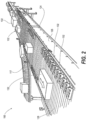
- FIG. 2 illustrates the linear sortation conveyor 102 has an elongate frame 124 including a pair of lateral side frames 126.
- An endless apron 128 formed of lateral slats 130 are supported for movement on the elongate frame 124.
- the endless apron 128 has a top conveying run and a bottom return run.
- Shoes or pushers 132 are received for lateral movement across the endless apron 128.
- Divert conveyors 117 are positioned respectively along at least one lateral side of the elongate frame 124 to receive articles 134 diverted by one or more pushers 132 from the distally-moving top conveying run of the endless apron 128.
- Articles 132 can be containers, totes, boxes, cartons, bags, pouches, unitarily packaged products, etc.
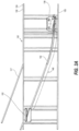
- FIG. 3A illustrates a pin guide assembly 135 that includes plurality of switches 136 that lie below the top conveying run of the endless apron 128.
- the switches 136 selectively divert articles 134 ( FIG. 2 ) to one of a plurality of divert locations 138 that are each associated with a divert conveyor 117.
- Respective divert guide paths 140 are disposed downstream of an associated switch 136 to receive a downwardly extending pin (not shown) from a selected pusher 132 ( FIG. 2 ). Diverted by the selected switch 136, the particular pusher 132 follows the selected divert guide path 140 to divert a selected article 134 ( FIG. 2 ).
- Each respective divert guide path 140 has an arcuate portion 142 having a continuously increasing slope without a breakpoint to laterally accelerate the diverted article 134 ( FIG. 2 ) without an abrupt initial force being applied.
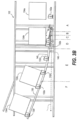
- FIG. 3B illustrates articles 134a - 134d being sorted by the linear sortation conveyor 102 with article 134d being farthest downstream.
- the pin guide assembly 135 interacts with selected pushers 132a - 132f to divert the articles 134a - 134d.
- Pushers 132a - 132f are not adjacent to each other and diverted pushers there between have been omitted for clarity.
- Pusher 132a is illustrated traveling along the home or charge path indicated generally by line 144. Unless diverted at switch 136, pusher 132a travels along the home path downstream of switch 136.
- Pusher 132b has been diverted and is traveling along straight section 146 of divert guide path 140.
- Pushers 132c and 132d are traveling along arcuate portion 142.
- pusher 132c is traveling at a lower divert angle than pusher 132d.
- Pushers 132e and 132f are traveling along straight section 150, at the final divert angle.
- a set of diverted pushers for article 134c may include additional pushers (not shown) between pushers 132d and 132e, as well as pushers located upstream and/or downstream thereof, or may just include the two pushers 132d and 132e illustrated. Since pusher 132d is traveling along arcuate portion 142, some pushers in between pushers 132d and 132e are likely bridged. By the time a pusher 132a - 132d reaches reentry 152 ( FIG.
- zone A upstream of switch 136, the pushers 132a - 132f are traveling straight in the home or charge path.
- zone B sets of one or more pushers 132a - 132f are selectively diverted from a home path 154 by switch 136, being guided on the pin from 0° to 20° through a small radius.
- zone C the angle is reduced from 20° to 3° relative to the longitudinal direction.
- the pushers 132a - 132f are guided through as large a radius as feasible, given length constraints. Up to this point, there preferably has been no contact with any articles 134a - 134d on the conveying surface, with each pusher 134a --- 134d being primarily guided by its pin.
- Article 134a is positioned to be spaced laterally away from the charge or home path 154 of the pusher 132a by a nominal distance of 3 inches.
- the pushers of the diverted set of pushers are close to but have not necessarily contacted the article 134b which is laterally aligned with the diverted set of pushers 132b.
- zone D the initial contact is made between the diverted set of pushers 132b and the article 134b being diverted.
- the article 134b being diverted is initially contacted by at least one of the pushers of the diverted set of pushers 132b.
- each carton is preferably positioned to the switch side of linear sortation conveyor 106, being single file and edge aligned such that the edge of the article 134 is parallel to the longitudinal direction.
- Differently positioned article 134 may limit the effectiveness: the system is designed for maximum effectiveness with article 134 being edge aligned and spaced a nominal distance of three (3) inches from the edge of the pushers 132 traveling along the home path.
- the contact zone falls within zone D, such as along straight section 146, with the divert angle of the pusher making initial contact being 3°. It is noted that within a linear portion of the divert guide path, the pushers have a constant lateral speed and thus no lateral acceleration.
- zone D The length and angle of zone D is calculated to produce initial engagement between the diverted pushers and the laterally aligned cartons being diverted within zone D. It is noted that the straight section of zone D may be omitted, with arcuate portion 142 mating directly with exit section 8g, with the divert angle at which the initial pusher to contact the carton is traveling when it initially contacts the carton, also referred to as the initial contact divert angle, being low enough that the impact between the pushers and the cartons does not result in an out-of-control situation.
- the initial engagement should preferably be as gentle as possible, such that the force with which the carton is contacted when divert of the carton is initiated is sufficiently low enough to maintain control throughout the entire range of longitudinal speeds at which the sortation conveyor operates.
- Article 134 under control during divert reliably and repeatably reach the divert, and the articles 134 are reliably not rotated substantially beyond the final divert angle, upset or toppled.
- Control in a material handling system 100 is determined by the articles 134 for which the material handling system 100 is used.
- a material handling system 100 does not lack control at operating speeds because cartons for which the system is not designed, or cartons for which the system is not typically used, cannot be diverted under control.
- the inability of a linear sortation conveyor 106 constructed in accordance with the present innovation to control unique cartons which are different from the articles 134 for which the linear sortation conveyor 106 was designed or is used, does not mean that the sortation conveyor does not maintain control of articles 134 being diverted.
- the measure of control is that of the articles 134 for which the system is designed or used.
- the acceleration rate or rates of at least the first pusher 132 of the diverted set of pushers to contact the carton being diverted must be sufficiently low enough to maintain control throughout the entire range of longitudinal speeds at which the linear sortation conveyor 106 functions.
- the present innovation is configured to minimize the maximum impact speed of the pushers 132 with the articles 134, resulting in a low initial impact force.
- Any article 134 being diverted must be laterally accelerated from its zero lateral speed to its final lateral speed.
- Each article 134 being diverted by the present innovation is laterally accelerated, whether initial contact occurs in a linear portion of the divert guide path 140 where the pushers 132 have no lateral acceleration, such as that defined by straight section 146, or in an arcuate portion of the divert guide path where the pushers are being laterally accelerated, such as that defined by arcuate portion 142.
- “chatter” minor fluctuations in lateral speed or lateral acceleration resulting from variation in longitudinal speed, tolerances and loading, are excluded from consideration.
- zone D is designed to generally have the initial contact and therefore initial impact of the pushers on the cartons occur within zone D, although some pushers may have initial contact within zone E or F, depending on bridging.
- the divert angle of zone D functions to minimize lateral speed of pushers when they initially contact a carton. Even if bridging occurs, initial contact between a diverted set of pushers (the first contact by any of the diverted set) occurs at low lateral speed.
- the impact force results from the difference in lateral speed between the carton and the pushers: Since the cartons generally have no lateral speed prior to initiation of divert, the impact force generally is the result of only the lateral speed of the pusher.
- the diverted article 134 can bridge intermediate pushers 132 within the diverted set in zone E with the arcuate divert guide path. Such bridging also occurs if the initial contact zone portion is arcuate.
- zone E the direction of travel of pushers 132 traveling in zone E begins at 3' and ends at 20°.
- zone E the article 134 continues to be rotated, until the trailing edge of the carton reaches the end of zone E, at which location the rotation of the carton is completed, usually matching the final divert angle of straight section 150, which is 20° in the depicted apparatus.
- Arcuate portion 142 causes the pushers to gradually, not necessarily constantly, rotate and laterally accelerate the cartons, producing low forces there between.
- the acceleration is preferably below 1 g, and in the depicted apparatus it is less than 0.3 g.
- an arcuate portion 142 that limits the lateral acceleration of pushers when in contact with cartons to less than 0.4 g will result in desirable improvement in control.
- an arcuate section with a 15 foot radius, having a final divert angle of 20°, operating at 650 feet per minute results in an average lateral acceleration of about 0.25 g, with a maximum lateral acceleration of about 0.277 g
- an arcuate section with a twelve (12) foot radius, having a final divert angle of 20°, operating at 650 feet per minute results in an average lateral acceleration of about 0.32 g, with a maximum lateral acceleration of about 0.347 g
- an arcuate section with an 8 foot radius, having a final divert angle of 30°, operating at 650 feet per minute results in an average lateral acceleration of about 0.51 g, with a maximum lateral acceleration of about 0.62 g
- the curved divert guide path allows for better controlled carton handling. While a large radius for arcuate portion 142 is desirable, to take the pushers to their maximum lateral speed as gradually as possible, improvements from use of the present innovation may be seen at a radius as small as one foot providing improved control at lower speeds.
- the energy to laterally accelerate the cartons is initially imparted to the cartons at a low lateral speed, and is imparted thereafter at increasing lateral speeds until the lateral speed of the cartons match the final divert lateral speed.
- zone E As the diverted set of pushers travels through the arcuate portion 142 of divert guide path 140, the lateral speed of the diverted article 134 is increased, being laterally accelerated as the pushers 132 in contact with the article 134 are accelerated from a first speed at which the carton was initially contacted to a second speed at the end of zone E, at which the divert angle of the end 14b of divert guide path 140 preferably is approximately tangent to the divert angle of straight section 150, which is the final divert angle at which the diverted carton is delivered to the divert.
- pushers which may be bridged therein, and thus not in contact with the carton are also accelerated to the second speed at the end of zone E.
- FIG. 4 illustrates a material handling system 400 having a dynamic capacity recirculation system 402 that can accommodate high volumes of articles 404 that are not diverted by the VHS linear sortation conveyor 102.
- the dynamic capacity recirculation system 402 is managed by a recirculation sortation conveyor 408 that can switch articles such as cartons or totes to more than one recirculation destination, illustrated as three recirculation sortation conveyors 410 and two destination locations 411 such as chutes or Gaylords.
- the recirculation sortation conveyor 408 can incorporates aspects of pre-sorting and diverting with a "soft touch" as described for the linear sortation conveyor 106 ( FIG. 1 ) to facilitate VHS operation.
- the material handling system 400 receives articles in a receiving center 412 and may buffer inventory in a storage area, such as an automated storage/retrieval system (ASRS) 414.
- a warehouse management system (WMS) 416 can direct that articles 404 be brought out of ASRS 414.
- WMS 416 can determine what articles 404 have been received in the receiving center 412 and convey the articles 404 for sorting.
- Articles are accumulated on accumulation conveyors 418.
- a sortation controller 420 monitors the articles 404 on the accumulation conveyor and can receive information from WMS 416 as to destination and priority of these articles 404.
- Sortation controller 420 executes a zipper merge or slug merge operation to release articles 404 onto a merge conveyor 422.
- the articles are gapped on a gapping conveyor 426 before pass through the field of view of the scanner 424.
- Linear sortation conveyor 102 diverts each article 404 to an assigned destination, such as a selected divert conveyor 428 to a shipping center 430.
- Those articles 404 that are not delivered are then handled by the recirculation sortation conveyor 410.
- the recirculation sortation conveyor 410 presorts right or left respectively to align articles for a first and second recirculation sortation conveyor 432a - 432b.
- the recirculation sortation conveyor 410 can also divert certain cartons to a third recirculation sortation conveyor 432c.
- each recirculation sortation conveyor 432a - 432c has its own path back to become an accumulation input to the merge conveyor 422.
- the recirculation sortation conveyor 432a - 432c can themselves merge beforehand and can terminate at another accumulation conveyor 418.
- Sortation conveyor 420 can obtain positioning information for articles 404 to be recirculated from a vision system 434. Certain articles 404 may have been laterally, longitudinally, or rotationally displaced during transit of the linear sortation conveyor 410. Recirculation sortation conveyor 410 can adjust assignment of pushers 436 to compensate for this displacement. In addition, photoeyes 438 can be placed a key places on the material handling system 400 to economically obtain information as to the position of articles 404. Articles 404 can be relatively small, such as e-commerce parcels or polybags. Recirculation sortation conveyor 410 can divert certain articles to chutes 440 rather than recirculating the articles 404 for resorting.
- FIG.5 illustrates the linear sortation conveyor 102 inducting onto a transition conveyor section 501 and then onto an example recirculation sortation conveyor 500.
- the transition conveyor section 501 can be a roller conveyor or belt conveyor section with gap fillers 503 such as upwardly extending brush bristles or horizontal sliding plates.
- the transition conveyor section 501 covers any drive pulley curvature of the linear sortation conveyor 102.
- the recirculation sortation conveyor 500 includes an elongate frame 502 having a pair of lateral side frames 504.
- An endless apron 506 of slats 508 is supported for longitudinal movement on the elongate frame 502 to define a top conveying run and a bottom return run.
- the endless apron 506 of the recirculation sortation conveyor 500 is positioned downstream of a linear sortation conveyor 102 to receive the undiverted articles 404 ( FIG.4 ) at an offset lateral position. More than one pusher 510 is received for lateral movement across the endless apron 506 transverse to the longitudinal movement Each pusher 510 has a pin (not shown) extending below the top conveying run.
- FIG.6 illustrates the recirculation sortation conveyor 500 having a pin guide assembly 601 that is coupled between the elongate lateral frames 502 and upwardly presented to receive a pin 603 and thereby to guide each pusher 510.
- the pin guide assembly 601 includes an upstream pre-sort section 605 that positions the articles 404 selectively from an offset lateral position 607 to an opposite lateral position 609 of die top conveying run of the endless apron 506 ( FIG. 5 ), which are illustrated as left and right respectively.
- Recirculation sortation conveyors 520a - 520b are positioned downstream of the recirculation sortation conveyor 500 respectively to receive articles 404 presorted to one of the offset lateral position 607 and the opposite lateral position 609. Those articles 404 that are to be diverted are switched by a divert section 611 rather than continuing straight ahead onto recirculation sortation conveyors 520a - 520b.
- each pusher 510 is centered by left and right converging guides 613, 615. As assigned, each pusher 510 is selectively reset by setup switch 616 to continue on bottom straight guide 617 or to follow a bottom offset guide 619 to position the pusher 510 outside of the offset lateral position 607. Once the pusher 510 is returned to the starting point of the top conveying run of the endless apron 506 ( FIG.5 ), a calibration gate 621 can be activated to align the pusher 510 further outboard of the pin guide assembly 601 to traverse outside of a left side straight guide 623 for calibration purposes.
- Pushers 510 that are otherwise selected to be on this outboard side rather than the middle by the setup switch 616 are used to laterally reposition articles 404.
- Each outboard pusher 510 is selected nut is predicted to flank a particular article 404 mat is to be laterally and gentry repositioned to the opposite lateral position 609.
- the flanking pusher 510 is guided toward the center to a center passage 625 by a left converging guide 627.
- Pushers 510 mat were generally centered by the setup switch 616 are selected to slightly move toward the offset lateral position 607 by an angled guide 629 that brings these pushers 510 into the center passage 625 while aligning as necessary any article 404 in the offset lateral position 607 mat was assigned to remain in the offset lateral position 607.
- the pushers 510 can then follow a straight guide 631 that moves slightly toward the opposite lateral position 609, gently finishing lateral positioning of any articles that were assigned to opposite lateral position 609.
- the pushers 510 men enter a left shifting center passage 633 mat position the pushers 510 in the center of the endless apron 506 ( FIG.5 ), separated by a small amount from articles 404 mat may be to either side.
- Right-to-center guide 634 also directs any pushers 510 that may have been inadvertently on the opposite lateral position 609.
- Pins 603 of the pushers 510 then enter a first nested dual switch 635 having a first left switch 637 that can selectively direct a pusher 510 onto a leftward diverging guide 639 or a second right switch 641 that selectively direct a pusher 510 onto a rightward diverging guide 643. Any flanked article 404 is thereby diverted.
- a return guide 645 directs any diverted pusher to follow respectively a left or right straight path 647, 649 through the remainder of the divert section 611.
- FIG.6 illustrates a second nested dual switch 635 in which only the first left switch 637 is used to obtain another left divert destinationU D2" via a second leftward diverging guide 639. the second right switch 639 is not used. A third nested dual switch 635 is not used. It should be appreciated that any number of divert paths can be incorporated to achieve a desired number of recirculation paths, including no divert paths. In one or more embodiments, the recirculation sortation conveyor 500 can also be used to direct articles 404 to other locations that back to the linear sortation conveyor 102 ( FIG.3 ).
- FIG.7 illustrates the recirculation sortation conveyor 500 assigning pushers 510 to pre-sort and selectively divert articles ("A") 404 from an offset induct ("I") to one of five locations.
- pre-sorting left certain articles 404 are prepared to routing to left side divert destinations "D1" and “D2” or left side recirculation destination "D3".
- pre-sorting right certain articles 404 are prepared for right side recirculation destination "D4" or for right side divert destination "D5".
- Pushers 510 can be directed to an outboard and straight calibration path 701.
- Pushers 610 otherwise selected to be on the offset lateral position 607 follow a left-to-center path 703, moving any article 404 most to the way into the opposite lateral position 609.
- Each pusher 510 can then be allowed to transit along an undiverted, straight path 709, can be switched onto a first left divert path 711, switched right onto a right divert path 713, or switch onto a second left divert path 715.
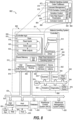
- an exemplary material handling system 800 of a distribution center processing architecture 802 is depicted wherein very high speed sortation controller 804 is implemented within a sortation control 806.
- Controller logic 808 stored in computer- readable, shared memory 810 is executed by processors 812 in a controller 814 of the material handling system 800.
- One function of the controller logic 808 can be machine control logic.
- the controller 814 can be a primary controller supported by a backup controller 815 such that maintenance personal could swap cables or connections in the event of a failure without undue service downtime. Alternatively, a supervising system or the self-diagnostics could cause automatic switching between primary and backup in the event of a failure.
- Scan logic refers to an implementation within the controller logic 808 wherein the processors 812 repeatedly execute a read input component 818, a solve logic component 820, and a write outputs component 822.
- the machine control logic can count scans to measure time.
- PLC programmable logic controller
- PC personal computer
- minicontroller or microcontroller, etc.
- the solve logic component 820 can incorporate IF-THEN-ELSE branching logic, motion control, simple to sophisticates, hardlined to configured.
- Data used by the solve logic component 820, can reside in the computer-readable, shared memory 810 or a data store device 824 (e.g., local, remote, cloud-based, etc.).
- a user interface 826 can be used to modify the solve logic component 820 such as by changing values that change the configuration or operation.
- the controller logic 808 can receive binary type inputs (e.g., switches, photo eyes, etc.) and generate binary type outputs (e.g., motor contacts, solenoid valves, lamp actuations, etc.).
- the user interface 826 can entail at least in part push button controls and lamps.
- controller logic 808 can include RS232 serial devices with cathode ray tube (CRT) screens and keyboards that enable dialog screens and data display along with printers for generating reports. Barcode scanning can detect items processed by the material handling system 800.
- wired and wireless communication within the material handling system 800 and distribution center processing architecture 802 enable more distributed and remotely isolated implementations.
- such communication architectures may employ bus couplers such a PROFIBUS and ETHERCAT.
- the scan 816 can be one of many control scans to support increased speeds and complexities for portions of the material handling system 800. Certain logic is required to be performed during shorter intervals than others and so the scans 816 can have different periodicities, often selected for convenience to occur as multiples of the shortest duration scan 816. Examples include scans 816 of 1 ms and 2 ms for motion control, 8 ms for a merge subsystem, and 211 ms for general conveyor.
- the material handling system 800 can incorporate host communications 828 to a warehouse execution system 830 using serial ports, Ethernet, file transfer protocol (FTP), Transfer Control Protocol/Internet Protocol (TCP/IP), etc. Thereby, the warehouse execution system 830 can make decisions for the material handling system 800. For example, a scanner 832 can see a barcode. The barcode is sent to the warehouse execution system 830, such as via a bridge 834. The warehouse execution system 830 responds with a destination. In response, the material handling system 800 causes the item with the barcode to go to that destination. Alternatively, the process can entail receiving a batch or download of destinations mapped to barcodes as part of a lookup table (LUT) for reference by the material handling system 800.
- Warehouse execution system can refer to an order fulfillment system, a warehouse management system, a warehouse control system, a host system, etc.
- the computer-readable shared memory 810 can allow execution of an operating system (e.g., Windows, LINX, etc.) 836 to execute with a real time extension 838.
- the real time extension 838 assures that the machine control logic (controller logic 808 ) gets to execute completely on the time schedule required. Variations in the execution schedule are measured in microseconds. This approach assures the kind of precision required for the machine control while retaining access to the power and flexibility of a general purpose Operating system (e.g., Windows).
- PLCs which can also be included for machine control, can operate in their own proprietary environments (hardware and software) and are integrated using communications. Data 840 from these communications is stored in computer-readable shared memory 810 for use in control decisions and for display on user interface 826.
- the data 840 is not controlled by the real time extension 838.
- other communicating devices 842 used in the control process e.g., scales, printers
- a private internal communications bus e.g., Ethernet
- the controller 814 can also have internal input/output drivers 845 to interface using specific communication protocols.
- the distribution center processing architecture 802 can include other systems external to the material handling system 800 that communicate via the bridge 834, such as a database 846, a warehouse control system (WCS) 848, and a warehouse management system (WMS) 850.
- the user interface 826 can facilitate remote or automated interaction via the user interface 826, depicted as a local application 852 and a web application 854.
- the controller 814 can include specific interfaces to support this interaction, such as a user interface data access component 856 to interact with user interface 826, middleware routing component 858 to interface with other external systems.
- Operating system services 860 and a device communication component 862 can also support the communications, such as sensors 864, actuators 866, diagnostic systems 868, and a sorter speed control 870.
- the controller logic 808 can be functional described as material handling control layers 872 of software functionality, such as the sortation control 806, that address certain subsystems within a distribution center: order fulfillment 874, carousel management 876, tilt tray/cross belt (TT/CB) control 878, conveyor control 8811, order manager 882 and route manager 884.
- order fulfillment 874 carousel management 876
- tilt tray/cross belt (TT/CB) control 878 tilt tray/cross belt (TT/CB) control 878
- conveyor control 8811 order manager 882 and route manager 884.
- running average carton length can be used. Then, after a reset, the expected average for the ten minute timer can be used. The same approach can be used for the one (1) minute average for recirculation. Alternatively or in addition, inter-slug gap can be considered in the calculation.
- processors include microprocessors, microcontrollers, digital signal processors (DSPs), field programmable gate arrays (FPGAs), programmable logic devices (PLDs), programmable logic controllers (PLCs), state machines, gated logic, discrete hardware circuits, and other suitable hardware configured to perform the various functionality described throughout this disclosure.
- DSPs digital signal processors
- FPGAs field programmable gate arrays
- PLDs programmable logic devices
- PLCs programmable logic controllers
- state machines gated logic, discrete hardware circuits, and other suitable hardware configured to perform the various functionality described throughout this disclosure.
- One or more processors in the processing system may execute instructions.
- a processing system that executes instructions to effect a result is a processing system which is configured to perform tasks causing the result, such as by providing instructions to one or more components of the processing system which would cause those components to perform acts which, either on their own or in combination with other acts performed by other components of the processing system would cause the result.
- Software shall be construed broadly to mean instructions, instruction sets, code, code segments, program code, programs, subprograms, software modules, applications, software applications, software packages, routines, subroutines, objects, executables, threads of execution, procedures, functions, etc., whether referred to as software, firmware, middleware, microcode, hardware description language, or otherwise.
- the software may reside on a computer-readable medium.
- the computer-readable medium may be a non-transitory computer-readable medium.
- Computer-readable medium includes, by way of example, a magnetic storage device (e.g., hard disk, floppy disk, magnetic strip), an optical disk (e.g., compact disk (CD), digital versatile disk (DVD)), a smart card, a flash memory device (e.g., card, stick, key drive), random access memory (RAM), read only memory (ROM), programmable ROM (PROM), erasable PROM (EPROM), electrically erasable PROM (EEPROM), a register, a removable disk, and any other suitable medium for storing software and/or instructions that may be accessed and read by a computer.
- a magnetic storage device e.g., hard disk, floppy disk, magnetic strip
- an optical disk e.g., compact disk (CD), digital versatile disk (DVD)
- a smart card e.g., a flash memory device (e.g., card, stick, key drive), random access
- the computer-readable medium may be resident in the processing system, external to the processing system, or distributed across multiple entities including the processing system.
- the computer-readable medium may be embodied in a computer-program product.
- a computer-program product may include a computer-readable medium in packaging materials.
- processor means devices which can be configured to perform the various functionality set forth in this disclosure, either individually or in combination with other devices.
- processors include microprocessors, microcontrollers, digital signal processors (DSPs), field programmable gate arrays (FPGAs), programmable logic devices (PLDs), programmable logic controllers (PLCs), state machines, gated logic, and discrete hardware circuits.
- DSPs digital signal processors
- FPGAs field programmable gate arrays
- PLDs programmable logic devices
- PLCs programmable logic controllers
- state machines gated logic, and discrete hardware circuits.
- processing system is used to refer to one or more processors, which may be included in a single device, or distributed among multiple physical devices.
- Instructions means data which can be used to specify physical or logical operations which can be performed by a processor. Instructions should be interpreted broadly to include, code, code segments, program code, programs, subprograms, software modules, applications, software applications, software packages, routines, subroutines, objects, executables, threads of execution, procedures, functions, hardware description language, middleware, etc., whether encoded in software, firmware, hardware, microcode, or otherwise.
- a computing device 900 will typically include a processor 901 coupled to volatile memory 902 and a large capacity nonvolatile memory, such as a disk drive 905 of Flash memory.
- the computing device 900 may also include a floppy disc drive 913 and a compact disc (CD) drive 914 coupled to the processor 901.
- the computing device 900 may also include a number of connector ports 915 coupled to the processor 901 for establishing data connections or receiving external memory devices, such as a USB or FireWire ⁇ TM connector sockets, or other network connection circuits for establishing network interface connections from the processor 901 to a network or bus, such as a local area network coupled to other computers and servers, the Internet, the public switched telephone network, and/or a cellular data network.
- the computing device 900 may also include the trackball or touch pad 917, keyboard 918, and display 919 all coupled to the processor 901.
- Embodiments or parts thereof may also be implemented on any of a variety of commercially available server devices, such as the server 1000 illustrated in FIG. 10 .
- a server 1000 typically includes a processor 1001 coupled to volatile memory 1002 and a large capacity nonvolatile memory, such as a disk drive 1003.
- the server 1000 may also include a floppy disc drive, compact disc (CD) or DVD disc drive 1004 coupled to the processor 1001.
- the server 1000 may also include network access ports 1006 coupled to the processor 1001 for establishing network interface connections with a network 1007, such as a local area network coupled to other computers and servers, the Internet, the public switched telephone network, and/or a cellular data network.
- a network 1007 such as a local area network coupled to other computers and servers, the Internet, the public switched telephone network, and/or a cellular data network.
- FIG. 11 illustrates a method 1100 of VHS sortation by a material handling system.
- method 1100 includes accessing, by a sortation controller, parameters for a target operating speed of the linear sortation conveyor, wherein the VHS parameters comprise an improvement for operation of at least 650 to 1000 feet per second (block 1102).
- the VHS parameters provide for 650 to 700 feet per second.
- TPM totes per minute
- Method 1100 includes commanding, by the sortation controller, slug releases from the more than one accumulation conveyor onto the merge conveyor (block 1104).
- Method 1100 includes gapping, by the sortation controller, each article in the train of articles on the gapping conveyor according to the VHS parameters (block 1106).
- Method 1100 includes scanning the train of articles conveyed between the merge conveyor and the linear sortation conveyor on the induction conveyor (block 1108).
- Method 1100 includes communicating, by the sortation controller, the identifying indicia to the warehouse execution system (block 1110).
- Method 1100 includes receiving, by the sortation controller, an assigned divert location for each article from the warehouse execution system (block 1112).
- Method 1100 includes switching, by the sortation controller, a selected divert switch for an assigned divert location for each article (block 1114).
- FIG. 12 illustrates a method 1200 of a sortation controller of a material handling system dynamically recirculating articles.
- the method 1200 includes communicating, by the sortation controller, via a device interface with a source of information for undiverted articles on a linear sortation conveyor that are being conveyed onto a recirculation sortation conveyor (block 1202).
- the method 1200 includes receiving an image of the articles on the linear sortation conveyor (block 1204).
- the method includes determining a predicted induction position of an undiverted article on an endless apron of the recirculation sortation conveyor (block 1206).
- the method 1200 includes determining whether capacity information is available for recirculation conveyors and any other divert location of the recirculation sortation conveyor (decision block 1208).
- the method 1200 includes round robin assigning the recirculation sortation conveyors and any other divert locations (block 1210). In response to determining that capacity information is available in decision block 1208, the method 1200 includes determining a capacity of at two recirculation conveyors that receive articles from a respective lateral side of the recirculation sortation conveyor and any divert location on a selected lateral side of the recirculation sortation conveyor (block 1212).
- method 1200 includes assigning a pre-sort section of the pin guide assembly to position the undiverted article on a selected lateral side of the endless apron corresponding to a selected one of two recirculation conveyors or the divert location having available capacity (block 1214). Method 1200 further determines whether the assignment is to any divert location (decision block 1216). In response to determining that the assignment is to not to any divert location in decision block 1216, the method 1200 returns to block 1202. In response to determining that the assignment is to any divert location in decision block 1216, the method 1200 includes assigning a divert section of the pin guide assembly to laterally divert to a selected divert location (block 1218). Then method 1200 returns to block 1202.
- FIG. 13 illustrates a method 1300 of dynamic recirculation control for a linear sortation conveyor of a material handling system.
- the method 1300 includes receiving, by a sortation controller, divert destination assignments from a warehouse execution system for a train of articles conveyed onto a linear sortation conveyor that has a primary recirculation path and a secondary recirculation path (block 1302). At least one of the primary and secondary recirculation paths are reachable by a particular article by lateral repositioning on an endless apron of the linear sortation conveyor.
- the method 1300 includes determining whether the warehouse execution system fails to timely assign the particular article to any divert destination (decision block 1304).
- method 1300 includes setting an impending recirculation status for the particular article (block 1306).
- the method 1300 includes communicating the assigned divert destination for the particular article to the linear sortation conveyor (block 1308).
- the method 1300 includes receiving an image of the linear sortation conveyor at a time after an assigned time for the linear sortation conveyor to divert the particular article at the assigned divert destination (block 1310).
- the method 1300 includes recognizing whether the particular article is in the image at a position on the linear sortation conveyor downstream of the assigned destination location (decision block 1312).
- the method 1300 includes setting an impending recirculation status for the particular article (block 1306). In response to recognizing the particular article is not in the image at the position on the linear sortation conveyor downstream of the assigned destination location in decision block 1312, the method 1300 includes returning to block 1302 to continue assigning and monitor articles of the train of articles.
- the method 1300 includes determining whether the material handling system is configured for balanced recirculation on the primary and secondary recirculation paths (decision block 1314). In response to determining that the material handling system is configured for balanced recirculation on the primary and secondary recirculation paths in decision block 1314, the method 1300 includes round robin assigning of the particular article along with any other articles in the train of articles having the status of impending recirculation (block 1316). Then method 1300 returns to block 1302 to continue assigning and monitor articles of the train of articles.
- the method 1300 includes determining whether a sensor indicates that the primary recirculation path has headroom to receive the particular article (decision block 1318). In response to determining that the sensor indicates that the primary recirculation path has headroom to receive the particular article in decision block 1318, the method 1300 includes assigning the particular article to the primary recirculation path, which can entail merely allowing the particular article to exit off of the end of the linear sortation conveyor (block 1320). Then method 1300 returns to block 1302 to continue assigning and monitor articles of the train of articles.
- the method 1300 includes communicating to the linear sortation conveyor an assignment of the particular article to the secondary recirculation path to prompt diverting at the last divert location (block 1322). Then method 1300 returns to block 1302 to continue assigning and monitor articles of the train of articles.
Landscapes
- Engineering & Computer Science (AREA)
- Mechanical Engineering (AREA)
- Discharge Of Articles From Conveyors (AREA)
- Branching, Merging, And Special Transfer Between Conveyors (AREA)
- Laminated Bodies (AREA)
Claims (12)
- Rücklaufsortierförderer (408, 410, 500), der Artikel (134, 134a-134d, 404), die nicht durch einen linearen Sortierförderer (106) eines Materialhandhabungssystems (100, 200, 400, 800) umgeleitet werden, dynamisch zurückführt, wobei der Rücklaufsortierförderer (408, 410, 500) umfasst:einen länglichen Rahmen (124, 502), der ein Paar lateraler Seitenrahmen (504) umfasst;ein Endlosplattenband (128, 506), das für eine Längsbewegung auf dem länglichen Rahmen (124, 502) gelagert ist, um eine obere Förderstrecke und eine untere Rückführstrecke zu definieren, und die stromabwärts des linearen Sortierförderers (106) positioniert ist, um an einer versetzten lateralen Position (607) eine Reihe von Artikeln (134, 134a-134d, 404) zu empfangen, die nicht von dem linearen Sortierförderer (106) umgeleitet werden;mehr als einen Schieber (132, 132a-132f, 510), der für eine laterale Bewegung über das Endlosplattenband (128, 506) quer zur Längsbewegung aufgenommen ist, wobei jeder Schieber (132, 132a-132f, 510) einen Stift (603) aufweist, der sich unter die obere Förderstrecke erstreckt;dadurch gekennzeichnet, dass der Rücklaufsortierförderer (408, 410, 500) umfasst:ein oder mehrere Umleitziele, die jeweils entlang einer ausgewählten lateralen Seite des länglichen Rahmens (124, 502) positioniert sind, um Artikel (134, 134a-134d, 404) zu empfangen, die von einem oder mehreren Schiebern (132, 132a-132f, 510) von der oberen Förderstrecke des Endlosplattenbandes (128, 506) umgeleitet werden, und um die empfangenen Artikel (134, 134a-134d, 404) auf einen ausgewählten Gaylord-Behälter (411), eine Rutsche (411, 440) und einen von zwei oder mehr Rücklaufsortierförderern (410, 432a-432c, 520a-520b) zu befördern;eine zwischen dem länglichen Paar von lateralen Seitenrahmen (504) gekoppelte Stiftführungsanordnung (135, 601), die nach oben ausgerichtet ist, um selektiv den Stift von jeweils mehr als einem Schieber (132, 132a-132f, 510) aufzunehmen, und die umfasst:einen stromaufwärts gelegenen Vorsortierabschnitt (605), der die Artikel (134, 134a-134d, 404) selektiv von der versetzten lateralen Position (607) zu einer gegenüberliegenden lateralen Position (609) der oberen Förderstrecke lateral in der Nähe des einen oder der mehreren Schieber positioniert; undeinen stromabwärts gelegenen Umleitungsabschnitt (611), der die Artikel selektiv zu jeweils zugewiesenen Umleitzielen umleitet, wobei der stromabwärts gelegene Umleitungsabschnitt Folgendes umfasst:eine Vielzahl von Schaltern zum selektiven Eingriff mit einem Stift eines ausgewählten Schiebers auf der oberen Förderstrecke; undeine Vielzahl von Umleitungsführungspfaden (140), wobei jeder entsprechende Umleitungsführungspfad (140) aus der Vielzahl von Umleitungsführungspfaden stromwabwärts eines entsprechenden zugewiesenen aus der Vielzahl von Schaltern angeordnet ist, um mit dem durch den zugewiesenen Schalter geschalteten Stift in Eingriff zu kommen, wobei jeder entsprechende Umleitungsführungspfad einen bogenförmigen Abschnitt (142) mit einem Eintritt in einem ersten Winkel umfasst, der sich gleichmäßig zu einem größeren zweiten Winkel zur Längsbewegung erhöht, wobei der bogenförmige Abschnitt die ausgewählten Artikel (134, 134a-134d, 404) ohne abrupte Stöße lateral beschleunigt, wobei der Umleitabschnitt (611) die ausgewählten Artikel (134, 134a-134d, 404) mit einer sanft ansteigenden lateralen Beschleunigung auf der oberen Förderstrecke für einen Betrieb mit sehr hoher Geschwindigkeit umleitet, ohne die ausgewählten Artikel umzuwerfen; undzwei oder mehr Rücklaufsortierförderer (410, 432a-432c, 520a-520b), die stromabwärts des Rücklaufsortierförderers (408, 410, 500) positioniert sind, um jeweils Artikel (134, 134a-134d, 404) zu empfangen, die zu einer der versetzten lateralen Position (607) und der gegenüberliegenden lateralen Position (609) vorsortiert sind.
- Rücklaufsortierförderer (408, 410, 500) nach Anspruch 1, ferner umfassend das Materialhandhabungssystem (100, 200, 400, 800), wobei das Materialhandhabungssystem (100, 200, 400, 800) umfasst:den linearen Sortierförderer (106), wobei der lineare Sortierförderer (106) umfasst:mehr als einen Umleitungsförderer (117, 117'), der jeweils entlang mindestens einer lateralen Seite des länglichen Rahmens (124, 502) positioniert ist, um Artikel (134, 134a-134d, 404) zu empfangen, die von einem oder mehreren Schiebern (132, 132a-132f, 510) von der oberen Förderstrecke des Endlosplattenbandes (128, 506) umgeleitet werden;eine Vielzahl von Schaltern (136), die Artikel (134, 134a-134d, 404) selektiv zu einer aus einer Vielzahl von Umleitungsstellen (138) umleiten, wobei die jeweiligen Umleitungsstellen (138) jeweils einem ausgewählten Umleitungsförderer (117, 117') zugewiesen sind;einen primären Rücklaufpfad (103), der nicht umgeleitete Artikel (134, 134a134d, 404) von einem stromabwärtigen Ende des linearen Sortierförderers (106) empfängt; undeinen sekundären Rücklaufpfad (103'), der mit einer letzten Umleitungsstelle (138) des linearen Sortierförderers (106) in Verbindung steht;eine Sortiersteuerung (102, 420, 804, 806), die mit dem linearen Sortierförderer (106) in Verbindung steht, wobei die Sortiersteuerung (102, 420, 804, 806) ein Prozessorteilsystem (812, 901, 1001) und einen Speicher (810, 902, 905, 1002, 1003) umfasst, der computerlesbare Anweisungen speichert, die, wenn sie von dem Prozessorteilsystem (812, 901, 1001) ausgeführt werden, das Materialhandhabungssystem (100, 200, 400, 800) so konfigurieren, dass es Vorgänge durchführt, die umfassen:Bestimmen, ob ein Artikel (134, 134a-134d, 404), der auf dem linearen Sortierförderer (106) befördert wird, keiner Umleitungsstelle (138) zugewiesen werden kann;als Reaktion auf das Bestimmen, dass ein bestimmter Artikel (134, 134a-134d, 404) keiner Umleitungsstelle (138) zugewiesen werden kann, Zuweisen des bestimmten Artikels (134, 134a-134d, 404) zu einem ausgewählten von dem primären Rücklaufpfad (103) und dem sekundären Rücklaufpfad (103').
- Rücklaufsortierförderer (408, 410, 500) nach Anspruch 2, wobei das Materialhandhabungssystem (100, 200, 400, 800) ferner einen Sensor (864) umfasst, der den Freiraum auf dem primären Rücklaufpfad (103) erkennt, um einen weiteren Artikel (134, 134a-134d, 404) zu empfangen, wobei die Sortiersteuerung (102, 420, 804, 806) mit dem Sensor (864) in Verbindung steht, und wobei die computerlesbaren Anweisungen, wenn sie von dem Prozessorteilsystem (812, 901, 1001) ausgeführt werden, ferner das Materialhandhabungssystem (100, 200, 400, 800) konfigurieren, um Vorgänge durchzuführen, die umfassen:Bestimmen, ob der Sensor (864) einen Freiraum auf dem primären Rücklaufpfad (103) anzeigt, um den bestimmten Artikel (134, 134a-134d, 404) zu empfangen; undals Reaktion auf das Bestimmen, dass der primäre Rücklaufpfad (103) keinen Freiraum aufweist, Zuweisen des bestimmten Artikels (134, 134a-134d, 404) an den sekundären Rücklaufpfad (103').
- Rücklaufsortierförderer (408, 410, 500) nach Anspruch 2 oder 3, wobei die computerlesbaren Anweisungen, wenn sie von dem Prozessorteilsystem (812, 901, 1001) ausgeführt werden, ferner das Materialhandhabungssystem (100, 200, 400, 800) konfigurieren, um Operationen durchzuführen, die umfassen:
Durchführen einer Rundlaufzuweisung des bestimmten Artikels (134, 134a-134d, 404) zu dem ausgewählten von dem primären Rücklaufpfad (103) und dem sekundären Rücklaufpfad (103'). - Rücklaufsortierförderer (408, 410, 500) nach Anspruch 1, ferner umfassend:
eine Sortiersteuerung (102, 420, 804, 806), umfassend:eine Vorrichtungskommunikationskomponente (862) zum Empfangen von Positionsinformationen der Reihe von Artikeln (134, 134a-134d, 404), die auf das Endlosplattenband (128, 506) eingeführt werden; undein Prozessorteilsystem (812, 901, 1001), das mit der Stiftführungsanordnung (135, 601) und der Vorrichtungskommunikationskomponente (862) in Verbindung steht, wobei das Prozessorteilsystem (812, 901, 1001) den Rücklaufsortierförderer (408, 410, 500) konfiguriert zum:Bestimmen, ob ein erster der zwei oder mehr Rücklaufsortierförderer (410, 432a-432c, 520a-520b) eine ausreichende Freiraumlücke aufweist, um einen Artikel (134, 134a-134d, 404) zu empfangen; undals Reaktion auf das Bestimmen, dass der erste der zwei oder mehr Rücklaufsortierförderer (410, 432a-432c, 520a-520b) keine ausreichende Freiraumlücke aufweist, um einen Artikel (134, 134a-134d, 404) zu empfangen, Konfigurieren der Stiftführungsanordnung (135, 601), um einen ausgewählten Artikel (134, 134a-134d, 404) zu einem zweiten der zwei oder mehr Rücklaufsortierförderer (410, 432a-432c, 520a-520b) umzuleiten. - Rücklaufsortierförderer (408, 410, 500) nach Anspruch 5, wobei das Prozessorteilsystem (812, 901, 1001) den Rücklaufsortierförderer (408, 410, 500) konfiguriert zum:Bestimmen, dass der lineare Sortierförderer (106) einen Stopp eingeleitet hat; undals Reaktion auf das Bestimmen, dass der lineare Sortierförderer (106) einen Stopp eingeleitet hat, Bestimmen, dass ein standardmäßiger Rücklaufsortierförderer (410, 432a-432c, 520a-520b) keine ausreichende Freiraumlücke aufweist.
- Rücklaufsortierförderer (408, 410, 500) nach Anspruch 5 oder 6, wobei das Prozessorteilsystem (812, 901, 1001) den Rücklaufsortierförderer (408, 410, 500) konfiguriert, um die Stiftführungsanordnung (135, 601) so zu konfigurieren, dass ein ausgewählter Artikel (134, 134a-134d, 404) zu dem zweiten der zwei oder mehr Rücklaufsortierförderer (410, 432a-432c, 520a-520b) umgeleitet wird, indem die Rücklaufziele in einer Rundlaufsequenz abgewechselt werden.
- Rücklaufsortierförderer (408, 410, 500) nach einem der Ansprüche 1 bis 7, wobei der stromaufwärts gelegene Vorsortierabschnitt (605) ausgewählte Artikel (134, 134a-134d, 404) mit einer sanft ansteigenden Beschleunigung lateral neu positioniert, um das Gleiten und die Fehlausrichtung der Artikel auf der oberen Förderstrecke in der Nähe des mehr als einen Schiebers (132, 132a-132f, 510) für den Betrieb mit sehr hoher Geschwindigkeit zu verringern.
- Rücklaufsortierförderer (408, 410, 500) nach Anspruch 8, wobei der stromaufwärts gelegene Vorsortierabschnitt (605) der Stiftführungsanordnung (135, 601) umfasst:einen Rückstellmechanismus, um jeden Schieber (132, 132a-132f, 510) selektiv in einer von einer äußeren Position und einer mittleren Position zu positionieren, die jeweils die versetzte laterale Position (607) der oberen Förderstrecke flankieren, die die eingeführten Artikel (134, 134a-134d, 404) empfängt; undeine Seitenverschiebeführung, die einen Schieber (132, 132a-132f, 510) in der äußeren Position empfängt und den Schieber (132, 132a-132f, 510) und einen flankierten Artikel (134, 134a-134d, 404) zu der gegenüberliegenden lateralen Position (609) der oberen Förderstrecke führt.
- Rücklaufsortierförderer (408, 410, 500) nach Anspruch 1, ferner umfassend eine Sortiersteuerung (102, 420, 804, 806), wobei die Sortiersteuerung (102, 420, 804, 806) umfasst:eine Vorrichtungskommunikationskomponente (862), die mit einer Informationsquelle für nicht umgeleitete Artikel (134, 134a-134d, 404) auf einem linearen Sortierförderer (106) in Verbindung steht, die auf einen Rücklaufsortierförderer befördert werden;ein Prozessorteilsystem (812, 901, 1001), das mit der Vorrichtungskommunikationskomponente (862) und einer Stiftführungsanordnung (135, 601) des Rücklaufsortierförderers (408, 410, 500) in Verbindung steht, wobei das Prozessorteilsystem (812, 901, 1001) den Rücklaufsortierförderer (408, 410, 500) konfiguriert zum:Bestimmen einer vorhergesagten Induktionsposition eines nicht umgeleiteten Artikels (134, 134a-134d, 404) auf einem Endlosplattenband (128, 506) des Rücklaufsortierförderers;Bestimmen einer Kapazität von zwei Rücklaufsortierförderern (410, 432a-432c, 520a-520b), die Artikel (134, 134a-134d, 404) von einer jeweiligen lateralen Seite des Rücklaufsortierförderers empfangen; undZuweisen eines Vorsortierabschnitts der Stiftführungsanordnung (135, 601), um den nicht umgeleiteten Artikel (134, 134a-134d, 404) auf einer ausgewählten lateralen Seite des Endlosplattenbandes (128, 506) zu positionieren, die einem ausgewählten der beiden Rücklaufsortierförderer (410, 432a432c, 520a-520b), die eine verfügbare Kapazität aufweisen, entspricht.
- Materialhandhabungssystem, umfassend den Rücklaufsortierförderer (408, 410, 500) nach Anspruch 1, wobei das Materialhandhabungssystem (100, 200, 400, 800) umfasst:einen linearen Sortierförderer (106), der mit einer Betriebsgeschwindigkeit in Längsrichtung arbeitet und der Artikel (134, 134a-134d, 404) empfängt, wobei der lineare Sortierförderer (106) umfasst:einen länglichen Rahmen (124, 502), der ein Paar lateraler Seitenrahmen (504) umfasst;ein Endlosplattenband (128, 506), das zur Bewegung auf dem länglichen Rahmen (124, 502) gelagert ist, um eine obere Förderstrecke und eine untere Rückführstrecke zu definieren;mehr als einen Schieber (132, 132a-132f, 510), der zur lateralen Bewegung über das Endlosplattenband (128, 506) empfangen wird;dadurch gekennzeichnet, dass das Materialhandhabungssystem (100, 200, 400, 800) Folgendes umfasst:mehr als einen Umleitungsförderer (117, 117'), der jeweils entlang mindestens einer lateralen Seite des länglichen Rahmens (124, 502) positioniert ist, um Artikel (134, 134a-134d, 404) zu empfangen, die von einem oder mehreren Schiebern (132, 132a-132f, 510) von der oberen Förderstrecke des Endlosplattenbandes (128, 506) umgeleitet werden;eine Vielzahl von Schaltern (136), die Artikel (134, 134a-134d, 404) selektiv zu einer von einer Vielzahl von Umleitungsstellen (138) umleiten;mehr als einen Schalter (136), der entsprechenden Umleitungsstellen (138) zugewiesen ist, die dem mehr als einen Umleitungsförderer (117, 117') zugewiesen sind;mehr als einen Umleitungsführungspfad (140), wobei jeder entsprechende Umleitungsführungspfad (140) der mehr als einen Umleitungsführungspfade (140) stromabwärts eines entsprechenden zugewiesenen mehr als einen Schalters (136) angeordnet ist, um einen ausgewählten Schieber (132, 132a-132f, 510) zu empfangen, der durch einen ausgewählten Schalter (136) in einen ausgewählten Umleitungsführungspfad (140) umgeleitet wird, um einen ausgewählten Artikel (134, 134a-134d, 404) umzuleiten, wobei jeder jeweilige Umleitungsführungspfad (140) einen bogenförmigen Abschnitt (142) mit einer kontinuierlich ansteigenden Neigung ohne Unterbrechungspunkt umfasst, um die umgeleiteten Artikel (134, 134a-134d, 404) lateral zu beschleunigen, ohne dass eine abrupte Anfangskraft angewendet wird;einen Scanner (115, 424, 434, 438, 832), der so positioniert ist, dass er die Position und die Identifizierungsmerkmale einer Reihe von Artikeln (134, 134a-134d, 404) erkennt, die auf den linearen Sortierförderer (106) befördert werden; undeine Sortiersteuerung (102, 420, 804, 806), die in Verbindung steht mit: einem Lagerausführungssystem (830); dem Scanner (115, 424, 434, 438, 832); dem linearen Sortierförderer (106); und dem Rücklaufsortierförderer (408, 410, 500);die Sortiersteuerung (102, 420, 804, 806), die computerlesbare Anweisungen auf einem Prozessor ausführt, der das Materialhandhabungssystem (100, 200, 400, 800) konfiguriert, um Operationen durchzuführen, die umfassen:Scannen der Reihe von Artikeln (134, 134a-134d, 404), die auf den linearen Sortierförderer (106) befördert werden;Übermitteln der Identifizierungskennzeichen an das Lagerausführungssystem (830) und Empfangen einer zugewiesenen Umleitungsstelle (138) für jeden Artikel (134, 134a-134d, 404);Umschalten eines ausgewählten Umleitungsschalters (136) für eine zugewiesene Umleitungsstelle (138) für jeden Artikel (134, 134a-134d, 404);Bestimmen, ob ein Artikel (134, 134a-134d, 404) nicht auf dem Endlosplattenband (128, 506) umgeleitet wurde;als Reaktion auf das Bestimmen, ob ein Artikel (134, 134a-134d, 404) nicht auf dem Endlosplattenband (128, 506) umgeleitet wurde, Zuweisen des Artikels (134, 134a-134d, 404) zu einem von zwei oder mehr Rücklaufsortierförderern (410, 432a-432c, 520a-520b); undÜbermitteln der Zuweisung an den Rücklaufsortierförderer (408, 410, 500), wobei die Zielbetriebsgeschwindigkeit des linearen Sortierförderers (106) zwischen 650 und 700 Fuß pro Sekunde liegt.
- Verfahren zur dynamischen Rückführung von Artikeln, die von einem linearen Sortierförderer (106) eines Materialhandhabungssystems (100, 200, 400, 800) nicht umgeleitet werden, wobei das Verfahren Folgendes umfasst:bei einem Endlosplattenband (128, 506), das für eine Längsbewegung auf einem länglichen Rahmen (124, 502) gelagert ist, umfassend ein Paar lateraler Seitenrahmen (124, 502), um eine obere Förderstrecke und eine untere Rückführstrecke zu definieren, und die stromabwärts des linearen Sortierförderers (106) positioniert ist, Empfangen an einer versetzten lateralen Position (607) einer Reihe von Artikeln (134, 134a-134d, 404), die nicht von dem linearen Sortierförderer (106) umgeleitet werden;Aufnehmen von mehr als einem Schieber (132, 132a-132f, 510) für eine laterale Bewegung über das Endlosplattenband (128, 506) quer zur Längsbewegung, wobei jeder Schieber (132, 132a-132f, 510) einen Stift (603) aufweist, der sich unter die obere Förderstrecke erstreckt;wobei das Verfahren durch Folgendes gekennzeichnet ist:bei einem oder mehreren Umleitzielen, die jeweils entlang einer ausgewählten lateralen Seite des länglichen Rahmens (124, 502) positioniert sind, Empfangen von Artikeln (134, 134a-134d, 404), die von einem oder mehreren Schiebern (132, 132a-132f, 510) von der oberen Förderstrecke des Endlosplattenbandes (128, 506) umgeleitet werden, und Befördern der empfangenen Artikel (134, 134a-134d, 404) auf einen ausgewählten Gaylord-Behälter (411), eine Rutsche (411, 440) und einen von zwei oder mehr Rücklaufsortierförderern (410, 432a-432c, 520a-520b);bei einer nach oben ausgerichteten Stiftführungsanordnung (135, 601), die zwischen dem länglichen Paar von lateralen Seitenrahmen (504) gekoppelt ist, selektives Empfangen des Stifts von entsprechend mehr als einem Schieber (132, 132a-132f, 510);bei einem stromaufwärts gelegenen Vorsortierabschnitt (605) der Stiftführungsanordnung, Positionieren der Artikel (134, 134a-134d, 404) selektiv von der versetzten lateralen Position (607) zu einer gegenüberliegenden lateralen Position (609) der oberen Förderstrecke lateral in der Nähe des einen oder der mehreren Schieber; undbei einem stromabwärts gelegenen Umleitungsabschnitt (611) der Stiftführungsanordnung, selektives Umleiten der Artikel zu entsprechend zugewiesenen Umleitzielen, was ein laterales Umleiten der ausgewählten Artikel (134, 134a-134d, 404) mit einer sanft ansteigenden lateralen Beschleunigung auf der oberen Förderstrecke für einen Betrieb mit sehr hoher Geschwindigkeit beinhaltet, ohne die ausgewählten Artikel umzuwerfen, wobei das selektive Umleiten umfasst:bei einer Vielzahl von Schaltern, selektives Eingreifen eines Stifts eines ausgewählten Schiebers auf der oberen Förderstrecke; undbei einer Vielzahl von Umleitungsführungspfaden (140), wobei jeder jeweilige Umleitungsführungspfad (140) der Vielzahl von Umleitungsführungspfaden stromabwärts eines entsprechenden zugewiesenen Schalters der Vielzahl von Schaltern angeordnet ist und mit dem durch den zugewiesenen Schalter umgeschalteten Stift in Eingriff steht,bei jedem entsprechenden Umleitungsführungspfad, der einen bogenförmigen Abschnitt (142), der einen Eingang in einem ersten Winkel aufweist, der sanft zu einem größeren zweiten Winkel zur Längsbewegung ansteigt, umfasst, laterales Beschleunigen der ausgewählten Artikel (134, 134a-134d, 404) ohne irgendwelche abrupten Stöße;bei zwei oder mehr Rücklaufsortierförderern (410, 432a-432c, 520a-520b), die jeweils stromabwärts des Rücklaufsortierförderers (408, 410, 500) positioniert sind, Empfangen von Artikeln (134, 134a-134d, 404), die zu einer der versetzten lateralen Position (607) und der gegenüberliegenden lateralen Position (609) vorsortiert sind.
Priority Applications (1)
| Application Number | Priority Date | Filing Date | Title |
|---|---|---|---|
| EP23197698.6A EP4309808A3 (de) | 2016-07-19 | 2017-07-18 | Linearsortierförderer mit dynamischer rückführungskapazität |
Applications Claiming Priority (3)
| Application Number | Priority Date | Filing Date | Title |
|---|---|---|---|
| US201662363887P | 2016-07-19 | 2016-07-19 | |
| US15/375,900 US10106330B2 (en) | 2013-06-07 | 2016-12-12 | Very high speed linear sortation conveyor with dynamic recirculation capacity |
| PCT/US2017/042480 WO2018017510A1 (en) | 2016-07-19 | 2017-07-18 | Linear sortation conveyor with dynamic recirculation capacity |
Related Child Applications (1)
| Application Number | Title | Priority Date | Filing Date |
|---|---|---|---|
| EP23197698.6A Division EP4309808A3 (de) | 2016-07-19 | 2017-07-18 | Linearsortierförderer mit dynamischer rückführungskapazität |
Publications (2)
| Publication Number | Publication Date |
|---|---|
| EP3487797A1 EP3487797A1 (de) | 2019-05-29 |
| EP3487797B1 true EP3487797B1 (de) | 2023-09-20 |
Family
ID=60989458
Family Applications (2)
| Application Number | Title | Priority Date | Filing Date |
|---|---|---|---|
| EP17748978.8A Active EP3487797B1 (de) | 2016-07-19 | 2017-07-18 | Linerarer sortierförderer mit dynamischer rücklaufkapazität, sowie verfahren |
| EP23197698.6A Pending EP4309808A3 (de) | 2016-07-19 | 2017-07-18 | Linearsortierförderer mit dynamischer rückführungskapazität |
Family Applications After (1)
| Application Number | Title | Priority Date | Filing Date |
|---|---|---|---|
| EP23197698.6A Pending EP4309808A3 (de) | 2016-07-19 | 2017-07-18 | Linearsortierförderer mit dynamischer rückführungskapazität |
Country Status (4)
| Country | Link |
|---|---|
| US (2) | US10106330B2 (de) |
| EP (2) | EP3487797B1 (de) |
| CN (1) | CN109562898B (de) |
| WO (1) | WO2018017510A1 (de) |
Families Citing this family (26)
| Publication number | Priority date | Publication date | Assignee | Title |
|---|---|---|---|---|
| US10106330B2 (en) * | 2013-06-07 | 2018-10-23 | Intelligrated Headquarters, Llc | Very high speed linear sortation conveyor with dynamic recirculation capacity |
| US9795995B2 (en) * | 2015-05-06 | 2017-10-24 | Intelligrated Headquarters, Llc | High-speed, dual-sided shoe sorter with offset induct |
| ITUA20161526A1 (it) * | 2016-03-10 | 2017-09-10 | System Logistics S P A | Sistema e metodo di ordinamento di elementi, in particolare per impacchettamento |
| US10696489B2 (en) | 2016-12-01 | 2020-06-30 | Packsize Llc | Balancing load among operational system zones |
| US10226794B2 (en) | 2017-07-18 | 2019-03-12 | Intelligrated Headquarters, Llc | Dynamic tray spacing |
| CA2975159A1 (en) * | 2017-08-03 | 2019-02-03 | Raptor Integration Inc. | Occlusionless scanner for workpieces |
| JP7077080B2 (ja) * | 2018-03-14 | 2022-05-30 | 株式会社東芝 | 物流システム、物流方法及びプログラム |
| CN109649910B (zh) * | 2018-12-12 | 2021-05-04 | 深圳拓新包装机械有限公司 | 电商物流分配方法 |
| EP3999458A4 (de) * | 2019-07-16 | 2024-01-03 | Fives Intralogistics Corp. | Reichweitenerfassendes förderpackungverwaltungssystem zur messung und steuerung der dichte von paketen auf einem förderer |
| US11008178B1 (en) * | 2020-02-07 | 2021-05-18 | Intelligrated Headquarters, Llc | System, apparatus, and method for detecting a fault in a pusher shoe of a shoe sortation conveyor |
| US12077384B2 (en) | 2020-05-26 | 2024-09-03 | Target Brands, Inc. | Systems and methods for high-speed warehouse order sortation |
| US11679419B2 (en) | 2020-10-02 | 2023-06-20 | AMP Robotics Corporation | Efficient material recovery facility |
| JP7027504B1 (ja) | 2020-10-26 | 2022-03-01 | トーヨーカネツ株式会社 | 仕分けコンベヤ装置 |
| US11952221B2 (en) | 2020-12-15 | 2024-04-09 | Express Scripts Strategic Development, Inc. | Dynamic package sortation device |
| DE102020134232A1 (de) * | 2020-12-18 | 2022-06-23 | Krones Aktiengesellschaft | Thermische Behandlungsvorrichtung und Verfahren zum Betreiben der thermischen Behandlungsvorrichtung |
| US20220272050A1 (en) * | 2021-02-25 | 2022-08-25 | Zebra Technologies Corporation | Systems and methods for allocating resources to execute functions |
| JP7318673B2 (ja) * | 2021-03-17 | 2023-08-01 | 株式会社ダイフク | 物品仕分け方法及び物品仕分け装置 |
| CN113296142B (zh) * | 2021-05-21 | 2023-01-17 | 山西中辐核仪器有限责任公司 | 传送带式安全帽污染监测仪 |
| CN113515083A (zh) * | 2021-07-07 | 2021-10-19 | 蓓安科仪(北京)技术有限公司 | 一种医院箱式物流控制方法 |
| WO2023023313A1 (en) * | 2021-08-19 | 2023-02-23 | Trew, Llc | Sortation conveyor with flexible divert guide |
| CN116550616A (zh) * | 2022-01-27 | 2023-08-08 | 浙江菜鸟供应链管理有限公司 | 物流对象传送方法、装置、分拣系统和供件台 |
| CN114546914B (zh) * | 2022-02-23 | 2024-04-26 | 北京奕斯伟计算技术股份有限公司 | 用于对多个通道信息执行数据处理的处理装置及系统 |
| CN114904783B (zh) * | 2022-05-24 | 2024-05-14 | 成都好伙伴网络科技有限公司 | 一种地下物流的分拣系统 |
| DE102022205209A1 (de) * | 2022-05-24 | 2023-11-30 | Dürkopp Fördertechnik GmbH | Fördervorrichtung und Förderverfahren für Waren |
| US12214969B2 (en) * | 2022-12-14 | 2025-02-04 | Intelligrated Headquarters, Llc | Speed control system for peripheral conveyors of sorter systems |
| CN116251766B (zh) * | 2023-01-05 | 2025-07-22 | 西安中科西光航天科技有限公司 | 一种基于高光谱的分类农作物传送处理设备 |
Family Cites Families (34)
| Publication number | Priority date | Publication date | Assignee | Title |
|---|---|---|---|---|
| US3361247A (en) * | 1966-03-28 | 1968-01-02 | Taylor & Gaskin | Article sorting system and method |
| US4884677A (en) | 1984-11-27 | 1989-12-05 | The Buschman Company | Package sortation conveyor |
| US4711341A (en) | 1984-11-27 | 1987-12-08 | The E. W. Buschman Company | Package sortation conveyor |
| US4717011A (en) * | 1986-04-30 | 1988-01-05 | The E.W. Buschman Company | Sorting conveyor with cross-over |
| US4732259A (en) | 1986-07-09 | 1988-03-22 | The E. W. Buschman Company | Sorting conveyor with cross-over |
| US5613591A (en) | 1992-11-09 | 1997-03-25 | Litton Industrial Automation Systems, Inc. | Sortation conveyor and devices |
| JP3895443B2 (ja) * | 1997-11-26 | 2007-03-22 | 株式会社ダイフク | 自動倉庫 |
| US6513641B1 (en) | 1999-10-12 | 2003-02-04 | Rapistan Systems Advertising Corp. | High rate induction system |
| US6478144B1 (en) | 2000-09-21 | 2002-11-12 | Fki Industries, Inc.'s, Fki Logistex Automation Division | Sliding shoe sorter and methods of using sliding shoe sorter |
| CA2449963A1 (en) * | 2001-06-07 | 2002-12-12 | David W. Zeitler | Tiered control architecture for material handling |
| US6575287B2 (en) * | 2001-10-25 | 2003-06-10 | Mark C. Garvey | Product conveying and accumulation system and method |
| AU2002346820B2 (en) | 2001-11-01 | 2006-09-07 | Siemens Aktiengesellschaft | Conveyor system with diverting track network |
| US6860376B1 (en) | 2002-04-08 | 2005-03-01 | Intelligrated, Inc. | Sortation system, components and methods |
| KR101033410B1 (ko) | 2003-02-07 | 2011-05-09 | 인텔리그레이티드 인코포레이티드 | 슬랫 분류 컨베이어 |
| MXPA05009676A (es) * | 2003-03-12 | 2006-03-08 | Intelligrated Inc | Transportador clasificador. |
| EP1758803A1 (de) * | 2004-06-21 | 2007-03-07 | Siemens Corporate Research, Inc. | Platzsparender hochleistungs-artikelvereinzeler |
| CA2569284C (en) * | 2004-09-23 | 2011-09-13 | Dematic Corp. | Positive displacement sorter |
| EP1993944A4 (de) * | 2006-02-24 | 2009-04-08 | Northrop Grumman Systems Corp | Verfahren zur sortierung von gegenständen |
| MX2008014501A (es) * | 2006-05-12 | 2009-01-27 | John D Moore | Aparatos y metodos de banda transportadora de clasificacion. |
| CA2844967C (en) | 2007-09-07 | 2016-02-02 | Dematic Corp. | Conveyor systems |
| JP4508233B2 (ja) | 2007-12-06 | 2010-07-21 | 村田機械株式会社 | 仕分け装置 |
| US8260574B1 (en) * | 2007-12-21 | 2012-09-04 | Dematic Corp. | Diagnostic device for material handling system and method of diagnosing |
| US8612050B2 (en) | 2008-07-29 | 2013-12-17 | Palo Alto Research Center Incorporated | Intelligent product feed system and method |
| CA2735512A1 (en) | 2010-04-01 | 2011-10-01 | Siemens Aktiengesellschaft | Method and apparatus for measuring a parameter during the transport of objects to a processing device |
| JP2012111577A (ja) | 2010-11-22 | 2012-06-14 | Okura Yusoki Co Ltd | 搬送装置 |
| JP5772520B2 (ja) | 2011-11-07 | 2015-09-02 | Jfeスチール株式会社 | ベルトコンベヤ蛇行防止装置 |
| WO2014078632A1 (en) * | 2012-11-16 | 2014-05-22 | Intelligrated Headquarters Llc | Selectable release mode merge subsystem |
| MX2015006898A (es) * | 2012-11-30 | 2016-01-25 | Intelligrated Headquarters Llc | Control de acumulacion. |
| EP2925646B1 (de) * | 2012-11-30 | 2019-05-08 | Intelligrated Headquarters LLC | Akkumulationssteuerung |
| US9108805B2 (en) | 2013-02-23 | 2015-08-18 | Patrick Thomas | Conveying apparatus |
| WO2014197552A1 (en) | 2013-06-05 | 2014-12-11 | Intelligrated Headquarters Llc | Sortation conveyor with piezoelectric actuation |
| US9738455B2 (en) | 2013-06-07 | 2017-08-22 | Intelligrated Headquarters Llc | Conveyor speed control |
| US10106330B2 (en) * | 2013-06-07 | 2018-10-23 | Intelligrated Headquarters, Llc | Very high speed linear sortation conveyor with dynamic recirculation capacity |
| CN104338688B (zh) * | 2014-10-22 | 2016-09-28 | 湖州科尼物流设备有限公司 | 一种货物宽度检测装置 |
-
2016
- 2016-12-12 US US15/375,900 patent/US10106330B2/en active Active
-
2017
- 2017-07-18 EP EP17748978.8A patent/EP3487797B1/de active Active
- 2017-07-18 CN CN201780043008.8A patent/CN109562898B/zh active Active
- 2017-07-18 WO PCT/US2017/042480 patent/WO2018017510A1/en not_active Ceased
- 2017-07-18 EP EP23197698.6A patent/EP4309808A3/de active Pending
-
2018
- 2018-09-18 US US16/134,522 patent/US10479611B2/en active Active
Also Published As
| Publication number | Publication date |
|---|---|
| US20190016539A1 (en) | 2019-01-17 |
| CN109562898B (zh) | 2021-01-22 |
| US10479611B2 (en) | 2019-11-19 |
| US20180022555A1 (en) | 2018-01-25 |
| EP3487797A1 (de) | 2019-05-29 |
| EP4309808A2 (de) | 2024-01-24 |
| CN109562898A (zh) | 2019-04-02 |
| EP4309808A3 (de) | 2024-04-03 |
| WO2018017510A1 (en) | 2018-01-25 |
| US10106330B2 (en) | 2018-10-23 |
| US20180170683A9 (en) | 2018-06-21 |
Similar Documents
| Publication | Publication Date | Title |
|---|---|---|
| EP3487797B1 (de) | Linerarer sortierförderer mit dynamischer rücklaufkapazität, sowie verfahren | |
| US10265732B2 (en) | High-speed, dual-sided shoe sorter with offset induct | |
| JP7804569B2 (ja) | モジュール式パッケージソートシステム | |
| US7497316B2 (en) | Sortation conveyor apparatus and methods | |
| CN104955587B (zh) | 用于分选的动态卸料补偿的方法、材料处理系统以及控制器 | |
| EP3439799B1 (de) | Objekterfassungs- und handhabungssystem | |
| CA2394783C (en) | Conveyor having variable speed control | |
| CA2656652C (en) | Conveyor systems and methods | |
| US8886356B2 (en) | Selectable release mode merge subsystem | |
| WO2018058020A1 (en) | Fully validated material handling with shuttle container delivery system | |
| US20090026041A1 (en) | Apparatus and method for sorting non-sorted containers in an order-picking system | |
| US9481516B1 (en) | Robotic sortation system | |
| CN108345278A (zh) | 具有竖直对齐的双托架的as/rs升降机 | |
| JPH05193735A (ja) | コンベア装置 | |
| US10040640B2 (en) | Side-by-side reducer conveyor | |
| WO2016039649A1 (en) | A conveying device | |
| WO2021236295A1 (en) | Parcel merging and alignment using diverting shoes |
Legal Events
| Date | Code | Title | Description |
|---|---|---|---|
| STAA | Information on the status of an ep patent application or granted ep patent |
Free format text: STATUS: UNKNOWN |
|
| STAA | Information on the status of an ep patent application or granted ep patent |
Free format text: STATUS: THE INTERNATIONAL PUBLICATION HAS BEEN MADE |
|
| PUAI | Public reference made under article 153(3) epc to a published international application that has entered the european phase |
Free format text: ORIGINAL CODE: 0009012 |
|
| STAA | Information on the status of an ep patent application or granted ep patent |
Free format text: STATUS: REQUEST FOR EXAMINATION WAS MADE |
|
| 17P | Request for examination filed |
Effective date: 20190115 |
|
| AK | Designated contracting states |
Kind code of ref document: A1 Designated state(s): AL AT BE BG CH CY CZ DE DK EE ES FI FR GB GR HR HU IE IS IT LI LT LU LV MC MK MT NL NO PL PT RO RS SE SI SK SM TR |
|
| AX | Request for extension of the european patent |
Extension state: BA ME |
|
| DAV | Request for validation of the european patent (deleted) | ||
| DAX | Request for extension of the european patent (deleted) | ||
| STAA | Information on the status of an ep patent application or granted ep patent |
Free format text: STATUS: EXAMINATION IS IN PROGRESS |
|
| 17Q | First examination report despatched |
Effective date: 20200430 |
|
| GRAP | Despatch of communication of intention to grant a patent |
Free format text: ORIGINAL CODE: EPIDOSNIGR1 |
|
| STAA | Information on the status of an ep patent application or granted ep patent |
Free format text: STATUS: GRANT OF PATENT IS INTENDED |
|
| INTG | Intention to grant announced |
Effective date: 20230411 |
|
| GRAS | Grant fee paid |
Free format text: ORIGINAL CODE: EPIDOSNIGR3 |
|
| GRAA | (expected) grant |
Free format text: ORIGINAL CODE: 0009210 |
|
| STAA | Information on the status of an ep patent application or granted ep patent |
Free format text: STATUS: THE PATENT HAS BEEN GRANTED |
|
| AK | Designated contracting states |
Kind code of ref document: B1 Designated state(s): AL AT BE BG CH CY CZ DE DK EE ES FI FR GB GR HR HU IE IS IT LI LT LU LV MC MK MT NL NO PL PT RO RS SE SI SK SM TR |
|
| REG | Reference to a national code |
Ref country code: GB Ref legal event code: FG4D |
|
| REG | Reference to a national code |
Ref country code: CH Ref legal event code: EP |
|
| REG | Reference to a national code |
Ref country code: IE Ref legal event code: FG4D |
|
| REG | Reference to a national code |
Ref country code: DE Ref legal event code: R096 Ref document number: 602017074420 Country of ref document: DE |
|
| REG | Reference to a national code |
Ref country code: LT Ref legal event code: MG9D |
|
| PG25 | Lapsed in a contracting state [announced via postgrant information from national office to epo] |
Ref country code: GR Free format text: LAPSE BECAUSE OF FAILURE TO SUBMIT A TRANSLATION OF THE DESCRIPTION OR TO PAY THE FEE WITHIN THE PRESCRIBED TIME-LIMIT Effective date: 20231221 |
|
| REG | Reference to a national code |
Ref country code: NL Ref legal event code: MP Effective date: 20230920 |
|
| PG25 | Lapsed in a contracting state [announced via postgrant information from national office to epo] |
Ref country code: SE Free format text: LAPSE BECAUSE OF FAILURE TO SUBMIT A TRANSLATION OF THE DESCRIPTION OR TO PAY THE FEE WITHIN THE PRESCRIBED TIME-LIMIT Effective date: 20230920 Ref country code: RS Free format text: LAPSE BECAUSE OF FAILURE TO SUBMIT A TRANSLATION OF THE DESCRIPTION OR TO PAY THE FEE WITHIN THE PRESCRIBED TIME-LIMIT Effective date: 20230920 Ref country code: NO Free format text: LAPSE BECAUSE OF FAILURE TO SUBMIT A TRANSLATION OF THE DESCRIPTION OR TO PAY THE FEE WITHIN THE PRESCRIBED TIME-LIMIT Effective date: 20231220 Ref country code: LV Free format text: LAPSE BECAUSE OF FAILURE TO SUBMIT A TRANSLATION OF THE DESCRIPTION OR TO PAY THE FEE WITHIN THE PRESCRIBED TIME-LIMIT Effective date: 20230920 Ref country code: LT Free format text: LAPSE BECAUSE OF FAILURE TO SUBMIT A TRANSLATION OF THE DESCRIPTION OR TO PAY THE FEE WITHIN THE PRESCRIBED TIME-LIMIT Effective date: 20230920 Ref country code: HR Free format text: LAPSE BECAUSE OF FAILURE TO SUBMIT A TRANSLATION OF THE DESCRIPTION OR TO PAY THE FEE WITHIN THE PRESCRIBED TIME-LIMIT Effective date: 20230920 Ref country code: GR Free format text: LAPSE BECAUSE OF FAILURE TO SUBMIT A TRANSLATION OF THE DESCRIPTION OR TO PAY THE FEE WITHIN THE PRESCRIBED TIME-LIMIT Effective date: 20231221 Ref country code: FI Free format text: LAPSE BECAUSE OF FAILURE TO SUBMIT A TRANSLATION OF THE DESCRIPTION OR TO PAY THE FEE WITHIN THE PRESCRIBED TIME-LIMIT Effective date: 20230920 |
|
| REG | Reference to a national code |
Ref country code: AT Ref legal event code: MK05 Ref document number: 1613292 Country of ref document: AT Kind code of ref document: T Effective date: 20230920 |
|
| PG25 | Lapsed in a contracting state [announced via postgrant information from national office to epo] |
Ref country code: NL Free format text: LAPSE BECAUSE OF FAILURE TO SUBMIT A TRANSLATION OF THE DESCRIPTION OR TO PAY THE FEE WITHIN THE PRESCRIBED TIME-LIMIT Effective date: 20230920 |
|
| PG25 | Lapsed in a contracting state [announced via postgrant information from national office to epo] |
Ref country code: IS Free format text: LAPSE BECAUSE OF FAILURE TO SUBMIT A TRANSLATION OF THE DESCRIPTION OR TO PAY THE FEE WITHIN THE PRESCRIBED TIME-LIMIT Effective date: 20240120 |
|
| PG25 | Lapsed in a contracting state [announced via postgrant information from national office to epo] |
Ref country code: AT Free format text: LAPSE BECAUSE OF FAILURE TO SUBMIT A TRANSLATION OF THE DESCRIPTION OR TO PAY THE FEE WITHIN THE PRESCRIBED TIME-LIMIT Effective date: 20230920 |
|
| PG25 | Lapsed in a contracting state [announced via postgrant information from national office to epo] |
Ref country code: ES Free format text: LAPSE BECAUSE OF FAILURE TO SUBMIT A TRANSLATION OF THE DESCRIPTION OR TO PAY THE FEE WITHIN THE PRESCRIBED TIME-LIMIT Effective date: 20230920 |
|
| PG25 | Lapsed in a contracting state [announced via postgrant information from national office to epo] |
Ref country code: SM Free format text: LAPSE BECAUSE OF FAILURE TO SUBMIT A TRANSLATION OF THE DESCRIPTION OR TO PAY THE FEE WITHIN THE PRESCRIBED TIME-LIMIT Effective date: 20230920 Ref country code: RO Free format text: LAPSE BECAUSE OF FAILURE TO SUBMIT A TRANSLATION OF THE DESCRIPTION OR TO PAY THE FEE WITHIN THE PRESCRIBED TIME-LIMIT Effective date: 20230920 Ref country code: IS Free format text: LAPSE BECAUSE OF FAILURE TO SUBMIT A TRANSLATION OF THE DESCRIPTION OR TO PAY THE FEE WITHIN THE PRESCRIBED TIME-LIMIT Effective date: 20240120 Ref country code: ES Free format text: LAPSE BECAUSE OF FAILURE TO SUBMIT A TRANSLATION OF THE DESCRIPTION OR TO PAY THE FEE WITHIN THE PRESCRIBED TIME-LIMIT Effective date: 20230920 Ref country code: EE Free format text: LAPSE BECAUSE OF FAILURE TO SUBMIT A TRANSLATION OF THE DESCRIPTION OR TO PAY THE FEE WITHIN THE PRESCRIBED TIME-LIMIT Effective date: 20230920 Ref country code: CZ Free format text: LAPSE BECAUSE OF FAILURE TO SUBMIT A TRANSLATION OF THE DESCRIPTION OR TO PAY THE FEE WITHIN THE PRESCRIBED TIME-LIMIT Effective date: 20230920 Ref country code: AT Free format text: LAPSE BECAUSE OF FAILURE TO SUBMIT A TRANSLATION OF THE DESCRIPTION OR TO PAY THE FEE WITHIN THE PRESCRIBED TIME-LIMIT Effective date: 20230920 Ref country code: SK Free format text: LAPSE BECAUSE OF FAILURE TO SUBMIT A TRANSLATION OF THE DESCRIPTION OR TO PAY THE FEE WITHIN THE PRESCRIBED TIME-LIMIT Effective date: 20230920 Ref country code: PT Free format text: LAPSE BECAUSE OF FAILURE TO SUBMIT A TRANSLATION OF THE DESCRIPTION OR TO PAY THE FEE WITHIN THE PRESCRIBED TIME-LIMIT Effective date: 20240122 |
|
| PG25 | Lapsed in a contracting state [announced via postgrant information from national office to epo] |
Ref country code: PL Free format text: LAPSE BECAUSE OF FAILURE TO SUBMIT A TRANSLATION OF THE DESCRIPTION OR TO PAY THE FEE WITHIN THE PRESCRIBED TIME-LIMIT Effective date: 20230920 Ref country code: IT Free format text: LAPSE BECAUSE OF FAILURE TO SUBMIT A TRANSLATION OF THE DESCRIPTION OR TO PAY THE FEE WITHIN THE PRESCRIBED TIME-LIMIT Effective date: 20230920 |
|
| REG | Reference to a national code |
Ref country code: DE Ref legal event code: R097 Ref document number: 602017074420 Country of ref document: DE |
|
| PG25 | Lapsed in a contracting state [announced via postgrant information from national office to epo] |
Ref country code: DK Free format text: LAPSE BECAUSE OF FAILURE TO SUBMIT A TRANSLATION OF THE DESCRIPTION OR TO PAY THE FEE WITHIN THE PRESCRIBED TIME-LIMIT Effective date: 20230920 |
|
| PLBE | No opposition filed within time limit |
Free format text: ORIGINAL CODE: 0009261 |
|
| STAA | Information on the status of an ep patent application or granted ep patent |
Free format text: STATUS: NO OPPOSITION FILED WITHIN TIME LIMIT |
|
| PG25 | Lapsed in a contracting state [announced via postgrant information from national office to epo] |
Ref country code: DK Free format text: LAPSE BECAUSE OF FAILURE TO SUBMIT A TRANSLATION OF THE DESCRIPTION OR TO PAY THE FEE WITHIN THE PRESCRIBED TIME-LIMIT Effective date: 20230920 |
|
| 26N | No opposition filed |
Effective date: 20240621 |
|
| PG25 | Lapsed in a contracting state [announced via postgrant information from national office to epo] |
Ref country code: SI Free format text: LAPSE BECAUSE OF FAILURE TO SUBMIT A TRANSLATION OF THE DESCRIPTION OR TO PAY THE FEE WITHIN THE PRESCRIBED TIME-LIMIT Effective date: 20230920 |
|
| PG25 | Lapsed in a contracting state [announced via postgrant information from national office to epo] |
Ref country code: SI Free format text: LAPSE BECAUSE OF FAILURE TO SUBMIT A TRANSLATION OF THE DESCRIPTION OR TO PAY THE FEE WITHIN THE PRESCRIBED TIME-LIMIT Effective date: 20230920 |
|
| PG25 | Lapsed in a contracting state [announced via postgrant information from national office to epo] |
Ref country code: BG Free format text: LAPSE BECAUSE OF FAILURE TO SUBMIT A TRANSLATION OF THE DESCRIPTION OR TO PAY THE FEE WITHIN THE PRESCRIBED TIME-LIMIT Effective date: 20230920 |
|
| PG25 | Lapsed in a contracting state [announced via postgrant information from national office to epo] |
Ref country code: BG Free format text: LAPSE BECAUSE OF FAILURE TO SUBMIT A TRANSLATION OF THE DESCRIPTION OR TO PAY THE FEE WITHIN THE PRESCRIBED TIME-LIMIT Effective date: 20230920 |
|
| PG25 | Lapsed in a contracting state [announced via postgrant information from national office to epo] |
Ref country code: MC Free format text: LAPSE BECAUSE OF FAILURE TO SUBMIT A TRANSLATION OF THE DESCRIPTION OR TO PAY THE FEE WITHIN THE PRESCRIBED TIME-LIMIT Effective date: 20230920 |
|
| REG | Reference to a national code |
Ref country code: CH Ref legal event code: PL |
|
| PG25 | Lapsed in a contracting state [announced via postgrant information from national office to epo] |
Ref country code: LU Free format text: LAPSE BECAUSE OF NON-PAYMENT OF DUE FEES Effective date: 20240718 |
|
| PG25 | Lapsed in a contracting state [announced via postgrant information from national office to epo] |
Ref country code: LU Free format text: LAPSE BECAUSE OF NON-PAYMENT OF DUE FEES Effective date: 20240718 |
|
| PG25 | Lapsed in a contracting state [announced via postgrant information from national office to epo] |
Ref country code: CH Free format text: LAPSE BECAUSE OF NON-PAYMENT OF DUE FEES Effective date: 20240731 Ref country code: BE Free format text: LAPSE BECAUSE OF NON-PAYMENT OF DUE FEES Effective date: 20240731 |
|
| REG | Reference to a national code |
Ref country code: BE Ref legal event code: MM Effective date: 20240731 |
|
| PG25 | Lapsed in a contracting state [announced via postgrant information from national office to epo] |
Ref country code: IE Free format text: LAPSE BECAUSE OF NON-PAYMENT OF DUE FEES Effective date: 20240718 |
|
| PGFP | Annual fee paid to national office [announced via postgrant information from national office to epo] |
Ref country code: DE Payment date: 20250728 Year of fee payment: 9 |
|
| PGFP | Annual fee paid to national office [announced via postgrant information from national office to epo] |
Ref country code: GB Payment date: 20250722 Year of fee payment: 9 |
|
| PGFP | Annual fee paid to national office [announced via postgrant information from national office to epo] |
Ref country code: FR Payment date: 20250725 Year of fee payment: 9 |
|
| PG25 | Lapsed in a contracting state [announced via postgrant information from national office to epo] |
Ref country code: CY Free format text: LAPSE BECAUSE OF FAILURE TO SUBMIT A TRANSLATION OF THE DESCRIPTION OR TO PAY THE FEE WITHIN THE PRESCRIBED TIME-LIMIT; INVALID AB INITIO Effective date: 20170718 |
|
| PG25 | Lapsed in a contracting state [announced via postgrant information from national office to epo] |
Ref country code: HU Free format text: LAPSE BECAUSE OF FAILURE TO SUBMIT A TRANSLATION OF THE DESCRIPTION OR TO PAY THE FEE WITHIN THE PRESCRIBED TIME-LIMIT; INVALID AB INITIO Effective date: 20170718 |