EP3488676A1 - Getriebe für ein landwirtschaftliches anbaugerät - Google Patents
Getriebe für ein landwirtschaftliches anbaugerät Download PDFInfo
- Publication number
- EP3488676A1 EP3488676A1 EP18208499.6A EP18208499A EP3488676A1 EP 3488676 A1 EP3488676 A1 EP 3488676A1 EP 18208499 A EP18208499 A EP 18208499A EP 3488676 A1 EP3488676 A1 EP 3488676A1
- Authority
- EP
- European Patent Office
- Prior art keywords
- shaft
- gear
- intermediate shaft
- gears
- stage
- Prior art date
- Legal status (The legal status is an assumption and is not a legal conclusion. Google has not performed a legal analysis and makes no representation as to the accuracy of the status listed.)
- Granted
Links
Images
Classifications
-
- F—MECHANICAL ENGINEERING; LIGHTING; HEATING; WEAPONS; BLASTING
- F16—ENGINEERING ELEMENTS AND UNITS; GENERAL MEASURES FOR PRODUCING AND MAINTAINING EFFECTIVE FUNCTIONING OF MACHINES OR INSTALLATIONS; THERMAL INSULATION IN GENERAL
- F16H—GEARING
- F16H3/00—Toothed gearings for conveying rotary motion with variable gear ratio or for reversing rotary motion
- F16H3/02—Toothed gearings for conveying rotary motion with variable gear ratio or for reversing rotary motion without gears having orbital motion
- F16H3/08—Toothed gearings for conveying rotary motion with variable gear ratio or for reversing rotary motion without gears having orbital motion exclusively or essentially with continuously meshing gears, that can be disengaged from their shafts
- F16H3/087—Toothed gearings for conveying rotary motion with variable gear ratio or for reversing rotary motion without gears having orbital motion exclusively or essentially with continuously meshing gears, that can be disengaged from their shafts characterised by the disposition of the gears
- F16H3/091—Toothed gearings for conveying rotary motion with variable gear ratio or for reversing rotary motion without gears having orbital motion exclusively or essentially with continuously meshing gears, that can be disengaged from their shafts characterised by the disposition of the gears including a single countershaft
-
- A—HUMAN NECESSITIES
- A01—AGRICULTURE; FORESTRY; ANIMAL HUSBANDRY; HUNTING; TRAPPING; FISHING
- A01B—SOIL WORKING IN AGRICULTURE OR FORESTRY; PARTS, DETAILS, OR ACCESSORIES OF AGRICULTURAL MACHINES OR IMPLEMENTS, IN GENERAL
- A01B33/00—Tilling implements with rotary driven tools, e.g. in combination with fertiliser distributors or seeders, with grubbing chains, with sloping axles, with driven discs
- A01B33/08—Tools; Details, e.g. adaptations of transmissions or gearings
- A01B33/082—Transmissions; Gearings; Power distribution
-
- A—HUMAN NECESSITIES
- A01—AGRICULTURE; FORESTRY; ANIMAL HUSBANDRY; HUNTING; TRAPPING; FISHING
- A01B—SOIL WORKING IN AGRICULTURE OR FORESTRY; PARTS, DETAILS, OR ACCESSORIES OF AGRICULTURAL MACHINES OR IMPLEMENTS, IN GENERAL
- A01B71/00—Construction or arrangement of setting or adjusting mechanisms, of implement or tool drive or of power take-off; Means for protecting parts against dust, or the like; Adapting machine elements to or for agricultural purposes
- A01B71/06—Special adaptations of coupling means between power take-off and transmission shaft to the implement or machine
-
- A—HUMAN NECESSITIES
- A01—AGRICULTURE; FORESTRY; ANIMAL HUSBANDRY; HUNTING; TRAPPING; FISHING
- A01D—HARVESTING; MOWING
- A01D69/00—Driving mechanisms or parts thereof for harvesters or mowers
- A01D69/002—Driving mechanisms or parts thereof for harvesters or mowers driven by power take-off
-
- A—HUMAN NECESSITIES
- A01—AGRICULTURE; FORESTRY; ANIMAL HUSBANDRY; HUNTING; TRAPPING; FISHING
- A01D—HARVESTING; MOWING
- A01D69/00—Driving mechanisms or parts thereof for harvesters or mowers
- A01D69/06—Gearings
-
- F—MECHANICAL ENGINEERING; LIGHTING; HEATING; WEAPONS; BLASTING
- F16—ENGINEERING ELEMENTS AND UNITS; GENERAL MEASURES FOR PRODUCING AND MAINTAINING EFFECTIVE FUNCTIONING OF MACHINES OR INSTALLATIONS; THERMAL INSULATION IN GENERAL
- F16H—GEARING
- F16H3/00—Toothed gearings for conveying rotary motion with variable gear ratio or for reversing rotary motion
- F16H3/02—Toothed gearings for conveying rotary motion with variable gear ratio or for reversing rotary motion without gears having orbital motion
- F16H3/08—Toothed gearings for conveying rotary motion with variable gear ratio or for reversing rotary motion without gears having orbital motion exclusively or essentially with continuously meshing gears, that can be disengaged from their shafts
- F16H3/10—Toothed gearings for conveying rotary motion with variable gear ratio or for reversing rotary motion without gears having orbital motion exclusively or essentially with continuously meshing gears, that can be disengaged from their shafts with one or more one-way clutches as an essential feature
-
- F—MECHANICAL ENGINEERING; LIGHTING; HEATING; WEAPONS; BLASTING
- F16—ENGINEERING ELEMENTS AND UNITS; GENERAL MEASURES FOR PRODUCING AND MAINTAINING EFFECTIVE FUNCTIONING OF MACHINES OR INSTALLATIONS; THERMAL INSULATION IN GENERAL
- F16H—GEARING
- F16H57/00—General details of gearing
- F16H57/02—Gearboxes; Mounting gearing therein
- F16H57/021—Shaft support structures, e.g. partition walls, bearing eyes, casing walls or covers with bearings
-
- F—MECHANICAL ENGINEERING; LIGHTING; HEATING; WEAPONS; BLASTING
- F16—ENGINEERING ELEMENTS AND UNITS; GENERAL MEASURES FOR PRODUCING AND MAINTAINING EFFECTIVE FUNCTIONING OF MACHINES OR INSTALLATIONS; THERMAL INSULATION IN GENERAL
- F16H—GEARING
- F16H2200/00—Transmissions for multiple ratios
- F16H2200/003—Transmissions for multiple ratios characterised by the number of forward speeds
- F16H2200/0034—Transmissions for multiple ratios characterised by the number of forward speeds the gear ratios comprising two forward speeds
Definitions
- the present invention relates to a transmission for an agricultural implement for attachment to a tractor or the like and driven by the tractor.
- an agricultural implement for attachment to a tractor is known, with working units, which are drivable by means of a mechanical drive train from a tractor PTO.
- the mechanical drive train comprises a transfer case having at least two output shafts that go to different sides, to which drive shafts can be connected for driving at least two working units.
- An attachment of this type may be, in particular, a mower or a hay-turning machine for processing hay in the form of a windrow or a tedder.
- the output shafts of the transfer case are not aligned with each other and the propeller shafts are connected to each other connected to the output shaft entangled.
- the present invention has as its object to propose a two-stage or multi-stage transmission for a machine to be connected, which is more compact, simple and stable and moreover allows the input shaft and the output shaft to be in the same plane.
- this object is achieved by a transmission for an agricultural implement according to claim 1.
- the attachable transmission for agricultural implements comprises an input shaft which is drivable by an agricultural machine, such as a tractor.
- This input shaft drives a pinion, which drives a sprocket via a hypoid or conical toothing.
- This sprocket is attached to an intermediate shaft.
- two gears are arranged with different dimensions.
- a friction clutch or clutch By means of a friction clutch or clutch, the larger gear of the two gears can be connected to the intermediate shaft.
- the two gears are always coupled to a gear on an output shaft, wherein in the connection gear / gear without friction clutch or clutch at least one of the associated with the respective shaft gears to which it is attached, a freewheel, wherein the output shaft in the same Plane is arranged as the input shaft.
- the output shaft may, for example, drive one or two mowers or devices.
- connection pinion / input shaft and / or gear on the Output shaft coupled to a gear with friction clutch via a one-way clutch arranged.
- the gear arrangement can advantageously be used according to the invention in several connectable agricultural equipment, but particularly advantageous milling, crushers or mulchers.
- the input shaft 1 of the agricultural implement may, for example, be connected to the PTO of an agricultural tractor, for example a tractor, which drives the input shaft 1.
- the drive means of the input shaft 1 are not shown.
- the Input shaft 1 is connected to a pinion 2.
- the connection between input shaft 1 and pinion 2 has a freewheel to avoid power transmission during engine shutdown of the tractor or the like due to inertia of certain mechanical organs.
- the input shaft 1 drives the pinion 2, which is coupled by means of a conical and / or hypoid tooth connection with a ring gear 3.
- the sprocket 3 is fixedly mounted on an intermediate shaft 12.
- the intermediate shaft 12 is rotatably supported by a bearing.
- two gears 4 and 5 of different dimensions are arranged on the intermediate shaft 12.
- the gears 4 and 5 are respectively coupled to respective gears 7 and 8.
- Both the gear 7 and the gear 8 are arranged on an output shaft 10.
- the output shaft 10 is in the same plane as the input shaft. 1
- the gear 7 or the gear 4 are connected to the respective shaft via a freewheel connection, which means that as soon as the gear 5 is connected via the friction clutch or clutch 6, the output shaft 10 rotates faster and one of the compounds intermediate shaft 12 / gear fifth or output shaft 10 / gear 7 is in free-running.
- the output shaft is rotatably supported by bearings on the sides.
- the output shaft 1 is preferably connected at its ends with a respective head of a mower or a mulcher.
- the entire housing 101 of the transmission is rotatably supported on a frame (not shown) via the bearings 9.
- This design of the transmission allows the PTO to be rotated relative to the output shaft 10 and vice versa. This is particularly advantageous for non-level tillage.
- a hydraulic pump 11 may be provided to control the friction clutch or clutch 6
- a configuration results, in which the sprocket 3 is arranged on one side of the axis of rotation of the pinion 2 in the frame 101 gear and the gears 4 and 5 and the friction clutch / clutch are arranged on the other side of the axis of rotation of the pinion 2.
- the friction clutch / clutch 6 can be arranged in a space formed between the ring gear 3 and the pinion 2 in the frame 101 of the transmission 100. In this way, the entire transmission 100 is more compact with resulting advantages.
Landscapes
- Engineering & Computer Science (AREA)
- Life Sciences & Earth Sciences (AREA)
- Environmental Sciences (AREA)
- Mechanical Engineering (AREA)
- General Engineering & Computer Science (AREA)
- Soil Sciences (AREA)
- Power Engineering (AREA)
- Structure Of Transmissions (AREA)
- Harvester Elements (AREA)
Abstract
Description
- Die vorliegende Erfindung bezieht sich auf ein Getriebe für ein landwirtschaftliches Anbaugerät zum Anbau an einer Zugmaschine oder ähnlichem und angetrieben durch die Zugmaschine.
- Aus der
EP 2 923 541 ist ein landwirtschaftliches Anbaugerät zum Anbau an einen Schlepper bekannt, mit Arbeitsaggregaten, die mittels eines mechanischen Antriebstrangs von einer Schlepperzapfwelle her antreibbar sind. Der mechanische Antriebsstrang umfasst ein Verteilergetriebe mit mindestens zwei zu verschiedenen Seiten gehenden Ausgangswellen, an die Gelenkwellen zum Antreiben von mindestens zwei Arbeitsaggregaten anschließbar sind. Ein Anbaugerät dieser Art kann insbesondere ein Mähwerk oder auch eine Heuwendemaschine zur Bearbeitung von Heu in der Form eines Schwadens oder ein Zetter sein. Die Ausgangswellen des Verteilergetriebes fluchten nicht zueinander und die Gelenkwellen sind zueinander verschränkt an der Ausgangswelle anschließbar. - Die vorliegende Erfindung stellt sich die Aufgabe ein zwei- bzw. mehrstufiges Getriebe für eine zu verbindende Maschine vorzuschlagen, das kompakter, einfach und stabiler ist und überdies ermöglicht, dass die Eingangswelle und die Ausgangswelle in derselben Ebene liegen.
- Gemäß der Erfindung wird diese Aufgabe durch ein Getriebe für ein landwirtschaftliches Anbaugerät gemäß Patentanspruch 1 gelöst.
- Das anschließbare Getriebe für landwirtschaftliche Anbaugeräte, insbesondere ein Mähwerk oder Mulchgerät, umfasst eine Eingangswelle, die durch eine landwirtschaftliche Maschine, wie zum Beispiel einen Schlepper antreibbar ist. Diese Eingangswelle treibt ein Ritzel an, das über eine hypoide oder konische Zahnung einen Zahnkranz antreibt. Dieser Zahnkranz ist an einer Zwischenwelle befestigt. Auf dieser Zwischenwelle sind zwei Zahnräder mit verschiedener Abmessungen angeordnet. Mittels einer Reibkupplung oder Kupplung kann das größere Zahnrad der beiden Zahnräder mit der Zwischenwelle verbunden werden. Die beiden Zahnräder sind immer jeweils mit einem Zahnrad an einer Ausgangswelle gekoppelt, wobei bei der Verbindung Zahnrad/Zahnrad ohne Reibkupplung oder Kupplung mindestens eines der mit der jeweiligen Welle verbundenen Zahnräder, an der es befestigt ist, ein Freilaufrad ist, wobei die Ausgangswelle in derselben Ebene angeordnet ist, wie die Eingangswelle. Die Ausgangswelle kann zum Beispiel ein oder zwei Mähwerke bzw. Geräte antreiben.
- Vorteilhafter Weise ist zwischen der Verbindung Ritzel/Eingangswelle und/oder Zahnrad, an der Ausgangswelle gekoppelt ein Zahnrad mit Reibkupplung über eine Freilaufkupplung angeordnet. Dadurch werden während der Abstellung des Motors oder der Zugmaschine oder ähnlichem Beschädigungen vermieden.
- Die Getriebeanordnung kann vorteilhafter Weise gemäß der Erfindung in mehreren anschließbaren landwirtschaftlichen Geräten verwendet werden, besonders vorteilhaft jedoch Fräsen, Brecher oder Mulchgeräte.
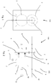
- Weitere Merkmale und Details der Erfindung gehen aus den Patentansprüchen und aus der folgenden Beschreibung einer bevorzugten, nicht begrenzenden, in den beigefügten Zeichnungen dargestellten Ausführungsform hervor. Es zeigen:
- Figur 1
- einen vertikalen Schnitt eines erfindungsgemäßen Getriebes, und
- Figur 2
- einen horizontalen Schnitt eines erfindungsgemäßen Getriebes.
- Mit 1 ist in
Figur 1 eine Eingangswelle des erfindungsgemäßen Getriebes 100 angegeben. Die Eingangswelle 1 des landwirtschaftlichen Anbaugerätes kann zum Beispiel mit der Zapfwelle einer landwirtschaftlichen Zugmaschine zum Beispiel eines Traktors verbunden, die/der die Eingangswelle 1 antreibt. Die Antriebsmittel der Eingangswelle 1 sind nicht dargestellt. Die Eingangswelle 1 ist mit einem Ritzel 2 verbunden. Vorteilhafter Weise weist die Verbindung zwischen Eingangswelle 1 und Ritzel2 einen Freilauf auf, um eine Kraftübertragung während des Abschaltens des Motors der Zugmaschine oder ähnlichen aufgrund der Trägheit von gewissen mechanischen Organen zu vermeiden. Die Eingangswelle 1 treibt das Ritzel 2 an, das mittels einer konischen und/oder hypoiden Zahnverbindung mit einem Zahnkranz 3 gekoppelt ist. - Der Zahnkranz 3 ist auf einer Zwischenwelle 12 fest angeordnet. Die Zwischenwelle 12 wird durch ein Lager drehbar getragen. Auf der Zwischenwelle 12 sind zwei Zahnräder 4 und 5 verschiedener Abmessungen angeordnet.
- Die Zahnräder 4 und 5 sind jeweils mit entsprechenden Zahnrädern 7 und 8 gekoppelt.
- Sowohl das Zahnrad 7 als auch das Zahnrad 8 sind auf einer Ausgangswelle 10 angeordnet. Die Ausgangswelle 10 liegt in derselben Ebene wie die Eingangswelle 1.
- Über eine Reibkupplung bzw. Kupplung 6 wird das Zahnrad 5, das Rad größerer Abmessung als das Zahnrad 4, mit der Zwischenwelle 12 gekoppelt. Ist das Zahnrad über die Reibkupplung bzw. Kupplung 6 nicht gekoppelt, ist dieses frei laufend. Über die Koppelung des Zahnrades 5 mit der Zwischenwelle 12 überträgt diese die Kraft über das Zahnrad 8 auf die Ausgangswelle 10.
- Das Zahnrad 7 oder das Zahnrad 4 sind mit der jeweiligen Welle über eine Freilaufverbindung verbunden, was bedeutet, dass sobald das Zahnrad 5 über die Reibkupplung bzw. Kupplung 6 verbunden ist, die Ausgangswelle 10 sich schneller dreht und eine der Verbindungen Zwischenwelle 12/Zahnrad 5 oder Ausgangswelle 10/Zahnrad 7 sich im Freilauf befindet.
- Durch dieses Freilaufsystem Reibkupplung/Kupplung Zahnräder und Wellen sind zwei verschiedene Ausganggeschwindigkeiten der Ausgangswelle 10 möglich. Die Ausgangswelle wird durch Lager auf den Seiten drehbar getragen. Die Ausgangswelle 1 ist bevorzugter Weise an ihren Enden mit jeweils einem Kopf eines Mähwerkes oder eines Mulchgerätes verbunden.
- Das gesamte Gehäuse 101 des Getriebes wird drehbar auf einem Rahmen (nicht dargestellt) über die Lager 9 getragen.
- Diese Ausbildung des Getriebes erlaubt, dass die Zapfwelle gegenüber der Ausgangswelle 10 gedreht werden kann und umgekehrt. Dies ist besonders vorteilhaft bei nicht ebenen Bodenbearbeitungen.
- Eine hydraulische Pumpe 11 kann zur Steuerung der Reibkupplung bzw. Kupplung 6 vorgesehen sein
- Als bevorzugte Ausführungsform ergibt sich eine Ausbildung, in der der Zahnkranz 3 auf einer Seite der Drehachse des Ritzels 2 im Rahmen 101 Getriebes angeordnet ist und die Zahnräder 4 und 5 und die Reibkupplung/Kupplung auf der anderen Seite der Drehachse des Ritzels 2 angeordnet sind. Auf diese Art und Weise kann die Reibkupplung/Kupplung 6 in einem Raum angeordnet werden, der zwischen dem Zahnkranz 3 und dem Ritzel 2 im Rahmen 101 des Getriebes 100 gebildet ist. Auf diese Weise ist das gesamte Getriebe 100 kompakter mit sich ergebenden Vorteilen .
- Es ist schließlich klar, dass an dem bis jetzt beschriebenen Getriebe 100 für den Fachmann naheliegende Zusätze, Änderungen oder Varianten vorgenommen werden können ohne den von den beigefügten Patentansprüchen festgelegten Schutzbereich zu verlassen.
- Legende der
- Bezugsziffern
- 1
- Eingangswelle
- 2
- Ritzel
- 3
- Zahnkranz
- 4,5,7,8
- Zahnrad
- 6
- Reibkupplung/Kupplung
- 9
- Lager
- 10
- Ausgangswelle
- 11
- Pumpe
- 12
- Zwischenwelle
- 100
- Getriebe
- 101
- Rahmen
Claims (7)
- Zwei- bzw. mehrstufiges Getriebe für ein landwirtschaftliches Anbaugerät zum Anbau an einer Zugmaschine, einem Schlepper oder ähnlichem, das über die Welle oder Zapfwelle der Zugmaschine, Schlepper oder ähnlichem angetrieben wird, umfassend eine Eingangswelle (1), die von der Zugmaschine, Schlepper oder ähnlichen angetrieben wird, dadurch gekennzeichnet, dass an der Eingangswelle (1) eintretend in das Gehäuse (101) ein Ritzel (2) angeordnet ist, wobei das Ritzel (2) von der Eingangswelle (1) angetrieben wird und über eine hypoide und/oder konische Zahnkoppelung einen an einer Zwischenwelle (12) befestigten Zahnkranz (3) antreibt, wobei die Zwischenwelle im Wesentlichen senkrecht zur Eingangswelle (1) angeordnet ist, wobei auf der Zwischenwelle (12) zwei Zahnräder (4, 5) mit verschiedenen Abmessungen angeordnet sind, und wobei mittels einer Reibkupplung bzw. Kupplung (6) eines der beiden Zahnräder (5) mit der Zwischenwelle (12) verbunden werden kann, wobei die Zahnräder (4,5) der Zwischenwelle jeweils mit einem an der Ausgangswelle (10) angeordneten Zahnrad (7,8) gekoppelt sind, und wobei in der Verbindung Zahnrad (4) der Zwischenwelle/Zahnrad (7) der Ausgangswelle (10) ohne Reibkupplung/Kupplung (6) mindestens eines der Zahnräder (4, 7) eine Freilaufverbindung mit der jeweiligen Welle (10, 12) aufweist, auf der es befestigt ist, und wobei die Ausgangswelle (10) in derselben Ebene der Eingangswelle angeordnet und das die Ausgangswelle (10) an mindestens einem Ende dieser außerhalb des Gehäuses (101) des Getriebes mit jeweils einem Antrieb einer Fräse, eines Brechers oder eines Mulchgerätes oder ähnlichem verbindbar ist.
- Zwei- bzw. mehrstufiges Getriebe (100) für ein landwirtschaftliches Anbaugerät nach Anspruch 1,
dadurch gekennzeichnet, dass das mit der Zwischenwelle (12) kuppelbare Zahnrad (5) das Rad mit der größeren Abmessungen der beiden auf der Zwischenwelle (12) angeordneten Zahnräder ist. - Zwei- bzw. mehrstufiges Getriebe (100) für ein landwirtschaftliches Anbaugerät nach einem der vorangehenden Ansprüche,
dadurch gekennzeichnet, dass das Zahnrad (4) mit kleinerer Abmessung der beiden auf der Zwischenwelle (12) angeordneten Zahnräder eine Freilaufverbindung mit der Zwischenwelle (12) aufweist. - Zwei- bzw. mehrstufiges Getriebe (100) für ein landwirtschaftliches Anbaugerät nach einem der Ansprüche von 1 bis 2,
dadurch gekennzeichnet, dass das Zahnrad (7) der Zwischenwelle (10), das mit dem Zahnrad (4) der Zwischenwelle mit kleinerer Abmessung der beiden auf der Zwischenwelle (12) angeordneten Zahnräder gekoppelt ist, eine Freilaufverbindung mit der Ausgangswelle (10) aufweist. - Zwei- bzw. mehrstufiges Getriebe (100) für ein landwirtschaftliches Anbaugerät nach einem der vorangehenden Ansprüche,
dadurch gekennzeichnet, dass die Verbindung zwischen Ritzel und Eingangswelle (1) und/oder zwischen dem Zahnrad (8), das mit dem Zahnrad (5) mit größerer Abmessung der beiden auf der Zwischenwelle (12) angeordneten Zahnräder gekoppelt ist, eine Freilaufverbindung mit der Ausgangswelle (10) aufweist. - Zwei- bzw. mehrstufiges Getriebe (100) für ein landwirtschaftliches Anbaugerät nach einem der vorangehenden Ansprüche,
dadurch gekennzeichnet, dass das Gehäuse (101) des Getriebes drehbar von zwei Lagern (9) getragen wird. - Zwei- bzw. mehrstufiges Getriebe (100) für ein landwirtschaftliches Anbaugerät nach einem der vorangehenden Ansprüche,
dadurch gekennzeichnet, dass auf einer Seite der Drehachse des Ritzels (2) im Rahmen (101) der Zahnkranz (3) und auf der anderen Seite der Drehachse des Ritzels (2) im Rahmen (101) die Zahnräder (4,5) und die Reibkupplung/Kupplung (6) angeordnet sind und die Reibkupplung/Kupplung (6) im Raum angeordnet ist, der zwischen dem Ritzel (2) und dem Zahnkranz (3) gebildet ist.
Applications Claiming Priority (1)
| Application Number | Priority Date | Filing Date | Title |
|---|---|---|---|
| IT201700136398 | 2017-11-28 |
Publications (2)
| Publication Number | Publication Date |
|---|---|
| EP3488676A1 true EP3488676A1 (de) | 2019-05-29 |
| EP3488676B1 EP3488676B1 (de) | 2020-05-27 |
Family
ID=61581528
Family Applications (1)
| Application Number | Title | Priority Date | Filing Date |
|---|---|---|---|
| EP18208499.6A Active EP3488676B1 (de) | 2017-11-28 | 2018-11-27 | Getriebe für ein landwirtschaftliches anbaugerät |
Country Status (3)
| Country | Link |
|---|---|
| US (1) | US10876597B2 (de) |
| EP (1) | EP3488676B1 (de) |
| ES (1) | ES2805104T3 (de) |
Cited By (1)
| Publication number | Priority date | Publication date | Assignee | Title |
|---|---|---|---|---|
| US10876597B2 (en) * | 2017-11-28 | 2020-12-29 | Seppi M. Spa | Transmission for towed agricultural equipment |
Citations (4)
| Publication number | Priority date | Publication date | Assignee | Title |
|---|---|---|---|---|
| FR1337291A (fr) * | 1961-06-23 | 1963-09-13 | Fahr Ag Maschf | Faneuse remorquée par tracteur |
| DE202007015176U1 (de) * | 2007-10-31 | 2009-03-12 | Alois Pöttinger Maschinenfabrik Gmbh | Landmaschine |
| EP2923541A1 (de) | 2014-03-28 | 2015-09-30 | Alois Pöttinger Maschinenfabrik GmbH | Landwirtschaftliches anbaugerät |
| CN106612641A (zh) * | 2016-12-14 | 2017-05-10 | 重庆茂旭科技有限责任公司 | 具有内外两侧传动结构的旋耕机 |
Family Cites Families (9)
| Publication number | Priority date | Publication date | Assignee | Title |
|---|---|---|---|---|
| GB805166A (en) | 1954-04-17 | 1958-12-03 | Degussa | Thickened liquids, pastes, sludges and suspensions |
| US3557879A (en) * | 1965-03-05 | 1971-01-26 | Lely Nv C Van Der | Cultivating implements |
| US3461656A (en) * | 1965-10-24 | 1969-08-19 | Carl Van Ausdall | Bed plate adjustment means relative to a lawnmower reel |
| US3457798A (en) * | 1967-09-25 | 1969-07-29 | Mast Foos Mfg Co Inc The | Transmission unit |
| US4805704A (en) * | 1985-10-12 | 1989-02-21 | Kobashi Kogyo Co., Ltd. | Rotary tilling device |
| JP4180981B2 (ja) * | 2003-06-13 | 2008-11-12 | 本田技研工業株式会社 | 差動装置 |
| DE102006005354A1 (de) * | 2006-02-07 | 2007-08-09 | Deere & Company, Moline | Getriebeanordnung |
| US9504203B2 (en) * | 2014-12-30 | 2016-11-29 | Deere & Company | Transmission arrangement for harvesting vehicles |
| ES2805104T3 (es) * | 2017-11-28 | 2021-02-10 | Seppi M Spa Ag | Transmisión para un apero agrícola |
-
2018
- 2018-11-27 ES ES18208499T patent/ES2805104T3/es active Active
- 2018-11-27 EP EP18208499.6A patent/EP3488676B1/de active Active
- 2018-11-28 US US16/202,404 patent/US10876597B2/en active Active
Patent Citations (4)
| Publication number | Priority date | Publication date | Assignee | Title |
|---|---|---|---|---|
| FR1337291A (fr) * | 1961-06-23 | 1963-09-13 | Fahr Ag Maschf | Faneuse remorquée par tracteur |
| DE202007015176U1 (de) * | 2007-10-31 | 2009-03-12 | Alois Pöttinger Maschinenfabrik Gmbh | Landmaschine |
| EP2923541A1 (de) | 2014-03-28 | 2015-09-30 | Alois Pöttinger Maschinenfabrik GmbH | Landwirtschaftliches anbaugerät |
| CN106612641A (zh) * | 2016-12-14 | 2017-05-10 | 重庆茂旭科技有限责任公司 | 具有内外两侧传动结构的旋耕机 |
Cited By (1)
| Publication number | Priority date | Publication date | Assignee | Title |
|---|---|---|---|---|
| US10876597B2 (en) * | 2017-11-28 | 2020-12-29 | Seppi M. Spa | Transmission for towed agricultural equipment |
Also Published As
| Publication number | Publication date |
|---|---|
| US10876597B2 (en) | 2020-12-29 |
| EP3488676B1 (de) | 2020-05-27 |
| US20190162273A1 (en) | 2019-05-30 |
| ES2805104T3 (es) | 2021-02-10 |
Similar Documents
| Publication | Publication Date | Title |
|---|---|---|
| DE102006047577B4 (de) | Antriebsanordnung für ein Aggregat eines landwirtschaftlichen Geräts oder einer landwirtschaftlichen Maschine | |
| DE68904246T2 (de) | Landmaschine mit mindestens einem waehrend der arbeit angetriebenen rechrad. | |
| EP3488676B1 (de) | Getriebe für ein landwirtschaftliches anbaugerät | |
| EP2457432B1 (de) | Getriebeanordnung für ein landwirtschaftliches Arbeitsgerät und zugehöriges Arbeitsgerät | |
| DE102012218912B4 (de) | Getriebe mit einem Grundgetriebe und schaltbarem Nebenabtrieb für einen Schiffsantrieb | |
| DE1013531B (de) | Antrieb fuer Ackerschlepper od. dgl. | |
| EP1258187A2 (de) | Antriebsanordnung für eine landwirtschaftliche Maschine | |
| DE602006000623T2 (de) | Endantrieb für ein Landwirtschaftsfahrzeug | |
| DE2611515A1 (de) | Einrichtung zur drehmomentuebertragung von einer antriebswelle auf zwei oder mehrere arbeitsorgane von landmaschinen | |
| DE720459C (de) | Rollgang mit Gruppenantrieb | |
| DE1036659B (de) | Getriebe, insbesondere fuer Ackerschlepper | |
| EP1466519A1 (de) | Rundballenpresse | |
| EP2184199B1 (de) | Selbstfahrende lenkbare Arbeitsmaschine | |
| DE689110C (de) | Bodenfraese | |
| DE1243531B (de) | Zapfwellen- und Hydraulikpumpenantrieb fuer landwirtschaftlich nutzbare Motorfahrzeuge | |
| DE678406C (de) | Antriebsgetriebe mit Schwungrad und Kupplung fuer Walzwerke | |
| DE882192C (de) | Getriebe fuer eine Zugmaschine, z. B. einen Schlepper | |
| DE326862C (de) | Maschinenanlasser | |
| DE828349C (de) | Zusatz-Untersetzungsgetriebe fuer Zugmaschinen | |
| EP0965258A1 (de) | Mähmaschine | |
| DE936183C (de) | Landwirtschaftlich genutztes Motorfahrzeug, insbesondere Zugmaschine | |
| AT226463B (de) | Getriebe für landwirtschaftliche Maschinen | |
| DE705574C (de) | Antriebsgetriebe fuer Walzwerke | |
| DE709796C (de) | Getriebeanordnung fuer Maschinen zum Ernten von Kartoffeln | |
| DE890456C (de) | Anordnung von Kraftabnahmestellen an Zugmaschinen und Ackerschleppern |
Legal Events
| Date | Code | Title | Description |
|---|---|---|---|
| PUAI | Public reference made under article 153(3) epc to a published international application that has entered the european phase |
Free format text: ORIGINAL CODE: 0009012 |
|
| STAA | Information on the status of an ep patent application or granted ep patent |
Free format text: STATUS: THE APPLICATION HAS BEEN PUBLISHED |
|
| AK | Designated contracting states |
Kind code of ref document: A1 Designated state(s): AL AT BE BG CH CY CZ DE DK EE ES FI FR GB GR HR HU IE IS IT LI LT LU LV MC MK MT NL NO PL PT RO RS SE SI SK SM TR |
|
| AX | Request for extension of the european patent |
Extension state: BA ME |
|
| STAA | Information on the status of an ep patent application or granted ep patent |
Free format text: STATUS: REQUEST FOR EXAMINATION WAS MADE |
|
| 17P | Request for examination filed |
Effective date: 20191126 |
|
| RBV | Designated contracting states (corrected) |
Designated state(s): AL AT BE BG CH CY CZ DE DK EE ES FI FR GB GR HR HU IE IS IT LI LT LU LV MC MK MT NL NO PL PT RO RS SE SI SK SM TR |
|
| GRAP | Despatch of communication of intention to grant a patent |
Free format text: ORIGINAL CODE: EPIDOSNIGR1 |
|
| STAA | Information on the status of an ep patent application or granted ep patent |
Free format text: STATUS: GRANT OF PATENT IS INTENDED |
|
| INTG | Intention to grant announced |
Effective date: 20200312 |
|
| RIN1 | Information on inventor provided before grant (corrected) |
Inventor name: SEPPI, LORENZ |
|
| GRAS | Grant fee paid |
Free format text: ORIGINAL CODE: EPIDOSNIGR3 |
|
| GRAA | (expected) grant |
Free format text: ORIGINAL CODE: 0009210 |
|
| STAA | Information on the status of an ep patent application or granted ep patent |
Free format text: STATUS: THE PATENT HAS BEEN GRANTED |
|
| AK | Designated contracting states |
Kind code of ref document: B1 Designated state(s): AL AT BE BG CH CY CZ DE DK EE ES FI FR GB GR HR HU IE IS IT LI LT LU LV MC MK MT NL NO PL PT RO RS SE SI SK SM TR |
|
| REG | Reference to a national code |
Ref country code: GB Ref legal event code: FG4D Free format text: NOT ENGLISH |
|
| REG | Reference to a national code |
Ref country code: CH Ref legal event code: EP |
|
| REG | Reference to a national code |
Ref country code: DE Ref legal event code: R096 Ref document number: 502018001533 Country of ref document: DE |
|
| REG | Reference to a national code |
Ref country code: AT Ref legal event code: REF Ref document number: 1273527 Country of ref document: AT Kind code of ref document: T Effective date: 20200615 |
|
| REG | Reference to a national code |
Ref country code: LT Ref legal event code: MG4D |
|
| PG25 | Lapsed in a contracting state [announced via postgrant information from national office to epo] |
Ref country code: PT Free format text: LAPSE BECAUSE OF FAILURE TO SUBMIT A TRANSLATION OF THE DESCRIPTION OR TO PAY THE FEE WITHIN THE PRESCRIBED TIME-LIMIT Effective date: 20200928 Ref country code: LT Free format text: LAPSE BECAUSE OF FAILURE TO SUBMIT A TRANSLATION OF THE DESCRIPTION OR TO PAY THE FEE WITHIN THE PRESCRIBED TIME-LIMIT Effective date: 20200527 Ref country code: FI Free format text: LAPSE BECAUSE OF FAILURE TO SUBMIT A TRANSLATION OF THE DESCRIPTION OR TO PAY THE FEE WITHIN THE PRESCRIBED TIME-LIMIT Effective date: 20200527 Ref country code: GR Free format text: LAPSE BECAUSE OF FAILURE TO SUBMIT A TRANSLATION OF THE DESCRIPTION OR TO PAY THE FEE WITHIN THE PRESCRIBED TIME-LIMIT Effective date: 20200828 Ref country code: IS Free format text: LAPSE BECAUSE OF FAILURE TO SUBMIT A TRANSLATION OF THE DESCRIPTION OR TO PAY THE FEE WITHIN THE PRESCRIBED TIME-LIMIT Effective date: 20200927 Ref country code: NO Free format text: LAPSE BECAUSE OF FAILURE TO SUBMIT A TRANSLATION OF THE DESCRIPTION OR TO PAY THE FEE WITHIN THE PRESCRIBED TIME-LIMIT Effective date: 20200827 Ref country code: SE Free format text: LAPSE BECAUSE OF FAILURE TO SUBMIT A TRANSLATION OF THE DESCRIPTION OR TO PAY THE FEE WITHIN THE PRESCRIBED TIME-LIMIT Effective date: 20200527 |
|
| REG | Reference to a national code |
Ref country code: NL Ref legal event code: MP Effective date: 20200527 |
|
| PG25 | Lapsed in a contracting state [announced via postgrant information from national office to epo] |
Ref country code: BG Free format text: LAPSE BECAUSE OF FAILURE TO SUBMIT A TRANSLATION OF THE DESCRIPTION OR TO PAY THE FEE WITHIN THE PRESCRIBED TIME-LIMIT Effective date: 20200827 Ref country code: RS Free format text: LAPSE BECAUSE OF FAILURE TO SUBMIT A TRANSLATION OF THE DESCRIPTION OR TO PAY THE FEE WITHIN THE PRESCRIBED TIME-LIMIT Effective date: 20200527 Ref country code: HR Free format text: LAPSE BECAUSE OF FAILURE TO SUBMIT A TRANSLATION OF THE DESCRIPTION OR TO PAY THE FEE WITHIN THE PRESCRIBED TIME-LIMIT Effective date: 20200527 Ref country code: LV Free format text: LAPSE BECAUSE OF FAILURE TO SUBMIT A TRANSLATION OF THE DESCRIPTION OR TO PAY THE FEE WITHIN THE PRESCRIBED TIME-LIMIT Effective date: 20200527 |
|
| PG25 | Lapsed in a contracting state [announced via postgrant information from national office to epo] |
Ref country code: AL Free format text: LAPSE BECAUSE OF FAILURE TO SUBMIT A TRANSLATION OF THE DESCRIPTION OR TO PAY THE FEE WITHIN THE PRESCRIBED TIME-LIMIT Effective date: 20200527 Ref country code: NL Free format text: LAPSE BECAUSE OF FAILURE TO SUBMIT A TRANSLATION OF THE DESCRIPTION OR TO PAY THE FEE WITHIN THE PRESCRIBED TIME-LIMIT Effective date: 20200527 |
|
| PG25 | Lapsed in a contracting state [announced via postgrant information from national office to epo] |
Ref country code: DK Free format text: LAPSE BECAUSE OF FAILURE TO SUBMIT A TRANSLATION OF THE DESCRIPTION OR TO PAY THE FEE WITHIN THE PRESCRIBED TIME-LIMIT Effective date: 20200527 Ref country code: SM Free format text: LAPSE BECAUSE OF FAILURE TO SUBMIT A TRANSLATION OF THE DESCRIPTION OR TO PAY THE FEE WITHIN THE PRESCRIBED TIME-LIMIT Effective date: 20200527 Ref country code: EE Free format text: LAPSE BECAUSE OF FAILURE TO SUBMIT A TRANSLATION OF THE DESCRIPTION OR TO PAY THE FEE WITHIN THE PRESCRIBED TIME-LIMIT Effective date: 20200527 Ref country code: RO Free format text: LAPSE BECAUSE OF FAILURE TO SUBMIT A TRANSLATION OF THE DESCRIPTION OR TO PAY THE FEE WITHIN THE PRESCRIBED TIME-LIMIT Effective date: 20200527 Ref country code: CZ Free format text: LAPSE BECAUSE OF FAILURE TO SUBMIT A TRANSLATION OF THE DESCRIPTION OR TO PAY THE FEE WITHIN THE PRESCRIBED TIME-LIMIT Effective date: 20200527 |
|
| REG | Reference to a national code |
Ref country code: ES Ref legal event code: FG2A Ref document number: 2805104 Country of ref document: ES Kind code of ref document: T3 Effective date: 20210210 |
|
| PG25 | Lapsed in a contracting state [announced via postgrant information from national office to epo] |
Ref country code: PL Free format text: LAPSE BECAUSE OF FAILURE TO SUBMIT A TRANSLATION OF THE DESCRIPTION OR TO PAY THE FEE WITHIN THE PRESCRIBED TIME-LIMIT Effective date: 20200527 Ref country code: SK Free format text: LAPSE BECAUSE OF FAILURE TO SUBMIT A TRANSLATION OF THE DESCRIPTION OR TO PAY THE FEE WITHIN THE PRESCRIBED TIME-LIMIT Effective date: 20200527 |
|
| REG | Reference to a national code |
Ref country code: DE Ref legal event code: R097 Ref document number: 502018001533 Country of ref document: DE |
|
| PLBE | No opposition filed within time limit |
Free format text: ORIGINAL CODE: 0009261 |
|
| STAA | Information on the status of an ep patent application or granted ep patent |
Free format text: STATUS: NO OPPOSITION FILED WITHIN TIME LIMIT |
|
| 26N | No opposition filed |
Effective date: 20210302 |
|
| PG25 | Lapsed in a contracting state [announced via postgrant information from national office to epo] |
Ref country code: SI Free format text: LAPSE BECAUSE OF FAILURE TO SUBMIT A TRANSLATION OF THE DESCRIPTION OR TO PAY THE FEE WITHIN THE PRESCRIBED TIME-LIMIT Effective date: 20200527 |
|
| PG25 | Lapsed in a contracting state [announced via postgrant information from national office to epo] |
Ref country code: MC Free format text: LAPSE BECAUSE OF FAILURE TO SUBMIT A TRANSLATION OF THE DESCRIPTION OR TO PAY THE FEE WITHIN THE PRESCRIBED TIME-LIMIT Effective date: 20200527 |
|
| PG25 | Lapsed in a contracting state [announced via postgrant information from national office to epo] |
Ref country code: LU Free format text: LAPSE BECAUSE OF NON-PAYMENT OF DUE FEES Effective date: 20201127 |
|
| REG | Reference to a national code |
Ref country code: BE Ref legal event code: MM Effective date: 20201130 |
|
| PG25 | Lapsed in a contracting state [announced via postgrant information from national office to epo] |
Ref country code: IE Free format text: LAPSE BECAUSE OF NON-PAYMENT OF DUE FEES Effective date: 20201127 |
|
| PG25 | Lapsed in a contracting state [announced via postgrant information from national office to epo] |
Ref country code: TR Free format text: LAPSE BECAUSE OF FAILURE TO SUBMIT A TRANSLATION OF THE DESCRIPTION OR TO PAY THE FEE WITHIN THE PRESCRIBED TIME-LIMIT Effective date: 20200527 Ref country code: MT Free format text: LAPSE BECAUSE OF FAILURE TO SUBMIT A TRANSLATION OF THE DESCRIPTION OR TO PAY THE FEE WITHIN THE PRESCRIBED TIME-LIMIT Effective date: 20200527 Ref country code: CY Free format text: LAPSE BECAUSE OF FAILURE TO SUBMIT A TRANSLATION OF THE DESCRIPTION OR TO PAY THE FEE WITHIN THE PRESCRIBED TIME-LIMIT Effective date: 20200527 |
|
| PG25 | Lapsed in a contracting state [announced via postgrant information from national office to epo] |
Ref country code: MK Free format text: LAPSE BECAUSE OF FAILURE TO SUBMIT A TRANSLATION OF THE DESCRIPTION OR TO PAY THE FEE WITHIN THE PRESCRIBED TIME-LIMIT Effective date: 20200527 |
|
| REG | Reference to a national code |
Ref country code: CH Ref legal event code: PL |
|
| PG25 | Lapsed in a contracting state [announced via postgrant information from national office to epo] |
Ref country code: BE Free format text: LAPSE BECAUSE OF NON-PAYMENT OF DUE FEES Effective date: 20201130 |
|
| REG | Reference to a national code |
Ref country code: DE Ref legal event code: R081 Ref document number: 502018001533 Country of ref document: DE Owner name: SEPPI M. AG, IT Free format text: FORMER OWNER: SEPPI M. SPA-AG, CALDARO, IT |
|
| GBPC | Gb: european patent ceased through non-payment of renewal fee |
Effective date: 20221127 |
|
| PG25 | Lapsed in a contracting state [announced via postgrant information from national office to epo] |
Ref country code: LI Free format text: LAPSE BECAUSE OF NON-PAYMENT OF DUE FEES Effective date: 20220630 Ref country code: CH Free format text: LAPSE BECAUSE OF NON-PAYMENT OF DUE FEES Effective date: 20220630 |
|
| PG25 | Lapsed in a contracting state [announced via postgrant information from national office to epo] |
Ref country code: GB Free format text: LAPSE BECAUSE OF NON-PAYMENT OF DUE FEES Effective date: 20221127 |
|
| REG | Reference to a national code |
Ref country code: AT Ref legal event code: MM01 Ref document number: 1273527 Country of ref document: AT Kind code of ref document: T Effective date: 20231127 |
|
| PG25 | Lapsed in a contracting state [announced via postgrant information from national office to epo] |
Ref country code: AT Free format text: LAPSE BECAUSE OF NON-PAYMENT OF DUE FEES Effective date: 20231127 |
|
| PG25 | Lapsed in a contracting state [announced via postgrant information from national office to epo] |
Ref country code: AT Free format text: LAPSE BECAUSE OF NON-PAYMENT OF DUE FEES Effective date: 20231127 |
|
| PGFP | Annual fee paid to national office [announced via postgrant information from national office to epo] |
Ref country code: DE Payment date: 20251128 Year of fee payment: 8 |
|
| PGFP | Annual fee paid to national office [announced via postgrant information from national office to epo] |
Ref country code: IT Payment date: 20251120 Year of fee payment: 8 |
|
| PGFP | Annual fee paid to national office [announced via postgrant information from national office to epo] |
Ref country code: FR Payment date: 20251125 Year of fee payment: 8 |
|
| PGFP | Annual fee paid to national office [announced via postgrant information from national office to epo] |
Ref country code: ES Payment date: 20251201 Year of fee payment: 8 |
|
| PGFP | Annual fee paid to national office [announced via postgrant information from national office to epo] |
Ref country code: AT Payment date: 20260410 Year of fee payment: 5 |