EP3488931A1 - Dispositif de séparation des mélanges de matières - Google Patents
Dispositif de séparation des mélanges de matières Download PDFInfo
- Publication number
- EP3488931A1 EP3488931A1 EP18000444.2A EP18000444A EP3488931A1 EP 3488931 A1 EP3488931 A1 EP 3488931A1 EP 18000444 A EP18000444 A EP 18000444A EP 3488931 A1 EP3488931 A1 EP 3488931A1
- Authority
- EP
- European Patent Office
- Prior art keywords
- container
- liquid
- screw conveyor
- conveyor
- screw
- Prior art date
- Legal status (The legal status is an assumption and is not a legal conclusion. Google has not performed a legal analysis and makes no representation as to the accuracy of the status listed.)
- Granted
Links
Images


Classifications
-
- B—PERFORMING OPERATIONS; TRANSPORTING
- B03—SEPARATION OF SOLID MATERIALS USING LIQUIDS OR USING PNEUMATIC TABLES OR JIGS; MAGNETIC OR ELECTROSTATIC SEPARATION OF SOLID MATERIALS FROM SOLID MATERIALS OR FLUIDS; SEPARATION BY HIGH-VOLTAGE ELECTRIC FIELDS
- B03B—SEPARATING SOLID MATERIALS USING LIQUIDS OR USING PNEUMATIC TABLES OR JIGS
- B03B5/00—Washing granular, powdered or lumpy materials; Wet separating
- B03B5/28—Washing granular, powdered or lumpy materials; Wet separating by sink-float separation
- B03B5/30—Washing granular, powdered or lumpy materials; Wet separating by sink-float separation using heavy liquids or suspensions
- B03B5/36—Devices therefor, other than using centrifugal force
-
- B—PERFORMING OPERATIONS; TRANSPORTING
- B03—SEPARATION OF SOLID MATERIALS USING LIQUIDS OR USING PNEUMATIC TABLES OR JIGS; MAGNETIC OR ELECTROSTATIC SEPARATION OF SOLID MATERIALS FROM SOLID MATERIALS OR FLUIDS; SEPARATION BY HIGH-VOLTAGE ELECTRIC FIELDS
- B03B—SEPARATING SOLID MATERIALS USING LIQUIDS OR USING PNEUMATIC TABLES OR JIGS
- B03B11/00—Feed or discharge devices integral with washing or wet-separating equipment
-
- B—PERFORMING OPERATIONS; TRANSPORTING
- B03—SEPARATION OF SOLID MATERIALS USING LIQUIDS OR USING PNEUMATIC TABLES OR JIGS; MAGNETIC OR ELECTROSTATIC SEPARATION OF SOLID MATERIALS FROM SOLID MATERIALS OR FLUIDS; SEPARATION BY HIGH-VOLTAGE ELECTRIC FIELDS
- B03B—SEPARATING SOLID MATERIALS USING LIQUIDS OR USING PNEUMATIC TABLES OR JIGS
- B03B5/00—Washing granular, powdered or lumpy materials; Wet separating
- B03B5/28—Washing granular, powdered or lumpy materials; Wet separating by sink-float separation
- B03B5/30—Washing granular, powdered or lumpy materials; Wet separating by sink-float separation using heavy liquids or suspensions
- B03B5/36—Devices therefor, other than using centrifugal force
- B03B5/40—Devices therefor, other than using centrifugal force of trough type
-
- B—PERFORMING OPERATIONS; TRANSPORTING
- B03—SEPARATION OF SOLID MATERIALS USING LIQUIDS OR USING PNEUMATIC TABLES OR JIGS; MAGNETIC OR ELECTROSTATIC SEPARATION OF SOLID MATERIALS FROM SOLID MATERIALS OR FLUIDS; SEPARATION BY HIGH-VOLTAGE ELECTRIC FIELDS
- B03B—SEPARATING SOLID MATERIALS USING LIQUIDS OR USING PNEUMATIC TABLES OR JIGS
- B03B11/00—Feed or discharge devices integral with washing or wet-separating equipment
- B03B2011/008—Screw dischargers
Definitions
- the invention relates to a device for separating material mixtures from buoyant and non-buoyant materials, such as stones, sand and wood, from waste mixtures with buoyant and non-floating materials, soils and / or biomass.
- Devices for separating material mixtures are known in the art.
- the known devices have the disadvantage that they do not separate the material mixtures clean from each other. As a result, it is necessary to send the mixtures several times through a separator to obtain a satisfactory result.
- Another disadvantage is that the known devices are regularly not feasible, so that a conversion to another site is often not possible, creating long transport routes for transporting the material mixtures arise. If the operator decides to implement the device nevertheless, this is associated with a high assembly and transport effort. Furthermore, there is a high level of wear on the devices caused, for example, by stones or sand.
- the object of the invention is therefore to propose a device for separating material mixtures, which no longer has at least one of the disadvantages described above.
- a device for separating material mixtures from buoyant and not buoyant materials such as from stones, sand, wood, waste mixtures or biomass, consisting of a provided in a frame, can be filled with liquid container, with a funnel-shaped filling opening and a unilaterally sloping bottom, wherein in the container at least two rotatably mounted and driven by at least one drive augers are arranged one above the other in the operating position, wherein the augers to the output side of the container rising or provided substantially parallel to the bottom of the container are so that they at least partially protrude during use of the device from the liquid, which is characterized in that between the upper screw conveyor and the lower screw conveyor at least one swirling device is provided.
- the swirling device ensures that buoyant components of the material mixture are carried to the surface of the liquid-filled container. There they are detected by the upper auger, which is provided ascending relative to the footprint, and transported out. At the end of the screw conveyor, the buoyant components, such as wood or other buoyant materials are conveyed by the screw conveyor on a conveyor belt.
- the non-buoyant components are detected by the lower auger and also transported out of the container. At the end of the container, these materials are also conveyed to a conveyor belt, which is of course provided separately from the conveyor belt with buoyant components.
- the swirling device can be designed as a nozzle, through which, for example, water at high pressure or overpressure is introduced into the container in order to swirl the material mixture.
- This mechanical swirling device can be designed, for example, in the manner of a whorl. Another possibility is the design of the swirling device in the manner of a turbine.
- the swirling device is a mechanical device in the form of an additional pan provided in the container, a sieve plate or a swirling plate or a rotatable shaft provided with vanes. Also With this type of formation of the swirling device, very good results can be achieved.
- the invention therefore comprises several variants.
- the disadvantages of the prior art are completely eliminated by the embodiment according to the invention.
- the wear in the device is also reduced by the swirling of the liquid. This results in longer operating times of the device according to the invention compared to the devices of the prior art.
- a first variant of the device according to the invention is characterized in that as swirling device at least one nozzle is provided, is pressed by the liquid with pressure in the container to fluidize the liquid in the container and to lead the buoyant components of the material mixture up to the upper auger ,
- This variant has already been briefly outlined before. It is advantageous if more than one nozzle is provided in the container, whereby the Verwirbelungs bin is still increased.
- At least one mechanical device such as. B. a separate tub for the upper screw conveyor with a sieve bottom between the upper and lower screw conveyor, a sieve plate itself as a swirling device, a swirling plate as a separating plate in the container, a rotatable, provided with wings shaft, a whirl, a Verwirbelungsschnecke or the like is provided.
- a separate tub for the upper screw conveyor with a sieve bottom between the upper and lower screw conveyor a sieve plate itself as a swirling device, a swirling plate as a separating plate in the container, a rotatable, provided with wings shaft, a whirl, a Verwirbelungsschnecke or the like is provided.
- a rotatable provided with wings shaft, a whirl, a Verwirbelungsschnecke or the like
- an additional tray with a sieve bottom is arranged below the upper conveyor screw in the container or that the sieve bottom comprises the upper conveyor screw at least halfway in the lower region, preferably in the form of a lattice.
- the additional tub also includes the upper auger approximately up to the Half of the diameter.
- the sieve tray is arranged in the lower region of the additional tray and preferably projects at least partially out of the upper liquid level in the container. The upper auger promotes cheaper way the liquid to the bottom of the sieve, creating a cycle through which the buoyant or light components get to the surface and can be removed by the upper auger.
- This design creates in the upper tub a cycle with buoyancy and water purification, whereby the light, buoyant components also get to the surface of the liquid.
- the heavier components reach the bottom of the additional tub to a heavy material opening provided there and from there into the area of the lower screw conveyor, which detects these heavy components and transported out of the device.
- the invention also works in a solution in which the sieve plate surrounds the circumference of the upper conveyor screw in the installed position below a grid.
- it is favorable for example, if the sieve bottom is arranged above the lower screw.
- This type of design already creates a suction through which the buoyant components above, d. H. remain in the detection range of the upper screw conveyor and can be transported away by this.
- the non-buoyant components arrive at the bottom of the sieve in the lower region seen in the conveying direction or at the lower end of the upper conveying screw. There they are lowered by a particular adjustable Schwerstoffö réelle in the region of the lower screw conveyor, whereby they can be detected by this and transported out.
- the nozzle is provided angle-adjustable in order to direct the liquid flow.
- the angle adjustment can be done for example via an externally controllable linkage.
- This angle adjustment can be configured both manually and engine operated.
- the angular adjustment of the liquid flow can also be done with appropriately arranged baffles.
- At least one adjusting device is provided for adjusting the liquid flow.
- This may be an adjusting device for adjusting the angle of the nozzle.
- the second embodiment of the invention described in a variant of this embodiment is characterized in that a tub as an additional tub in the container circumference upper auger in the installed position below, approximately up to half of the diameter surrounds and arranged the sieve bottom at the bottom of this additional tub is. It is advantageous if the sieve bottom preferably protrudes at least partially from the liquid or the upper liquid level. This creates the already described effect that the upper auger promotes the liquid to the bottom of the sieve, creating a buoyancy in the liquid. As a result, the light, floatable components reach the detection area of the upper auger, are caught by it and transported out. As already mentioned, the heavier components then reach the bottom of the additional tray. There they are passed through a heavy material opening in the container down into the area of the lower screw conveyor and detected by this and transported away.
- the variant of the invention described in the second place is also characterized in that a sieve bottom is provided between the lower and the upper conveyor screw. It is advantageous in this case if the sieve bottom surrounds the circumference of the upper conveyor worm in the installed position at least in the lattice-like manner in the lower region. Thus, the sieve bottom is located between the lower and upper auger.
- the sieve plate alone provides already in cooperation with at least one of the screw conveyors for a suction effect, whereby the buoyant components are conveyed upwards. As a result, they can then be transported out of the liquid mixture by the upper conveyor screw.
- the heavier components, such as stones stay down and slip down there due to the inclination of the sieve tray.
- at least one opening is provided as a passage for these heavy components in the lower region of the device, namely in the region of the lower screw conveyor.
- the upper screw conveyor has a larger diameter than the lower screw conveyor.
- the suction effect for the lighter or floating ingredients of the mixture is also increased, which significantly improves the removal.
- the distance of the screw helix of the upper screw conveyor is significantly greater than the distance of the lower screw helix of the lower screw conveyor.
- At least one opening is provided at the lower end of the sieve tray. It is particularly advantageous if this opening is designed as an adjustable heavy material opening. Thus one can react to different particle sizes of the heavy material to be removed. The non-buoyant material then passes through the heavy material opening into the area of the lower conveyor screw and is transported out of the device by it.
- a clever variant of the solution according to the invention proposes that a height adjustment between the frame and the container of the device is provided in order to change the position of the container in the frame.
- This can be reacted to different separating mixtures by the container can be positioned at a larger angle relative to the footprint or at a lower angle relative to the footprint. It has been found that thereby the separation effect can be significantly improved.
- the two screw conveyors can thus be reacted to different material mixtures.
- This can also affect the height of the liquid level in the container.
- the angular position of the container By adjusting the angular position of the container, the space in which the material mixture is introduced, narrower or seen from the volume smaller. This makes it clear that this also dividing effect can be favorably influenced.
- a level controller for controlling the water level and / or water inlet is provided on the device according to the invention. This, too, can influence the separation effect, ie. H. improve.
- the device according to the invention is characterized in that an angular adjustment of the container including the augers is provided, a water level and level change can be performed.
- At least two transport devices for the removal of the separated materials are arranged on the output side of the container so that the material passes from the screw conveyors to the respective associated transport device. This makes it possible to separate the buoyant and non-buoyant material components separately.
- the device according to the invention is characterized in that it can be implemented. It has, for example, at least one side wheels or rollers in a corresponding guide on the frame are arranged. On the side facing away from the rollers then, for example, a suspension device is arranged, by means of which the device can be moved by a motor-driven vehicle by means of a corresponding correspondingly designed pulling or towing device.
- FIG. 1 an embodiment of the device according to the invention is shown as a 3-dimensional representation.
- the device is schematically indicated by an arrow and the reference I.
- the entire device is arranged on a frame 1/2.
- a liquid-filled container 1 is arranged in the frame 1/2.
- This container 1 has seen from left to right on a sloping bottom 1/1.
- two screw conveyors 2, 3 are also arranged rising (seen from right to left).
- the lower screw conveyor 3 is provided for discharging non-buoyant materials, while the upper screw conveyor 2 detects the buoyant components and also out promotes. The conveyed out components arrive in each case on a conveyor belt.
- the non-buoyant components are transported to the lower conveyor belt as a transport device 5, while the buoyant components are transported by the screw conveyor 2 on the upper conveyor belt as a transport device 6.
- the arrow with the reference character C denotes the direction of the discharge.
- the filling opening for the material mixture is marked with the reference symbol A, while the reference symbol B schematically indicates the outlet of the material from the conveyor screw.
- the conveyor belts as transport devices 5, 6 are also attached to the frame 1/2. By means of unspecified adjusting the angle of attack of the conveyor belts can be changed. Below the lower transport device 5, two rollers 7/1 are provided in a guide 7. These are components for the implementation of the entire device I.
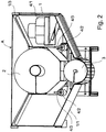
- FIG. 2 shows a view of the device according to the invention.
- the Fig. 1 from the back.
- the container 1 with its sloping bottom 1/1.
- the augers again bear the reference numerals 3 and 2.
- the swirling device 4 can be seen very nicely.
- a nozzle 4/2 is arranged in each case.
- the nozzles 4/2 are each angle-adjustable by means of a linkage as adjusting 4/3.
- FIG. 3 shows a 3-dimensional view of a section of the device according to the invention.
- the Fig. 1 to better illustrate an embodiment of the swirling device 4.
- the swirling device 4 has the following components, namely a pump 4/1, the nozzle 4/2 and the adjusting device 4/3, which is not recognizable here, for the nozzle 4/2.
- the nozzle has 4/2 three outlet openings for the exit of the liquid.
- FIG. 4 shows a similar view as FIG. 3 but from a different angle.
- the inventive device according to the Fig. 1 to 4 is filled for the separation process of the material mixture with liquid, such as water.
- the material mixture is filled by means of hoist or other suitable devices in the hopper A.
- the two screw conveyors 2 and 3 are set in a rotary motion.
- the material mixture is already set by the screw conveyors 2 and 3 in motion.
- the swirling device 4 then ensures that the buoyant components of the material mixture are guided to the upper screw conveyor 2.
- the upper screw conveyor 2 then conveys the upwardly swirled or guided, buoyant material to the upper conveyor belt as a transport device 6.
- the lower screw conveyor 3 promotes the non-buoyant, heavier material on the lower conveyor belt as a transport device 5.
- the swirling device is connected to a pump 4 / 1 equipped, which can be designed as a circulation pump, so not constantly new water must be added. Of course, according to fresh water must be refilled when the liquid level in the container 1 falls below a certain level. This embodiment of the invention makes it possible to obtain a very good separation result. At the same time a reduction of wear on the screw conveyor 2, 3 and on the container walls is achieved by the distribution of the liquid in the container 1.
- FIG. 5 a development of the device is shown, which is characterized in that the upper screw conveyor 2 in the lower region at least partially or in sections by an additional, arranged in the container 1 trough 43 is covered with a sieve bottom 41.
- the sieve bottom 41 is shown here schematically as a black area. In fact, however, the sieve bottom 41 is formed lattice-shaped, whereby liquid can drain down while the light, buoyant components of the material mixture remain above the sieve plate 41 and can be transported away by the upper screw conveyor 2.
- the upper conveyor screw 2 transports the liquid mixture to the sieve bottom 41.
- a turbulence with a buoyancy effect in the additional trough 43 is created, as a result of which the light, floatable components reach the top, are picked up by the conveyor worm 2 and transported out of the device.
- the liquid flows through the sieve bottom 41 into the lower region of the container 1.
- the heavy components of the material mixture slip down the bottom of the trough 43 and reach a heavy material opening 42. Through this heavy material opening 42, the heavy components slip into the lower region of the container 1. There they can be detected by the lower screw conveyor 3.
- the lower screw conveyor 3 then transports these components to the lower conveyor belt 5.
- the upper conveyor screw 2 is significantly larger, ie provided with a larger diameter.
- the spiral screw 2/1 are arranged at a greater distance c from each other than the screw spiral 3/1 of the lower screw conveyor 3.
- the distance of the lower spiral screw 3/1 is marked d.
- the sieve bottom 41 is provided as a swirling device 4 and ensures that a suction effect is produced, which also causes the light or floatable components of the material mixture in the area of the upper screw conveyor 3 arrive and can be removed by them.
- the solution according to the invention also works without an additional tub. In this case, for example, between the upper screw conveyor 2 and lower screw conveyor 3, only a sieve plate 41 may be provided which at least partially closed is. However, it is also possible to provide the container 1 with a separating plate, which also has an opening for receiving the sieve bottom 41. This is not shown in the drawing.
- a height adjustment 8 is provided.
- This height adjustment device 8 can be formed both purely mechanically, for example as a rack or as a hydraulic adjustment device. Consequently, the height of the container 1 can be changed via the axis 8/1.
- the maximum liquid level is indicated by a line which is touched by an arrow 10.
Landscapes
- Separation Of Solids By Using Liquids Or Pneumatic Power (AREA)
- Screw Conveyors (AREA)
Applications Claiming Priority (1)
| Application Number | Priority Date | Filing Date | Title |
|---|---|---|---|
| DE202017006034.5U DE202017006034U1 (de) | 2017-11-22 | 2017-11-22 | Vorrichtung zum Trennen von Materialgemischen |
Publications (2)
| Publication Number | Publication Date |
|---|---|
| EP3488931A1 true EP3488931A1 (fr) | 2019-05-29 |
| EP3488931B1 EP3488931B1 (fr) | 2021-09-08 |
Family
ID=62165293
Family Applications (1)
| Application Number | Title | Priority Date | Filing Date |
|---|---|---|---|
| EP18000444.2A Active EP3488931B1 (fr) | 2017-11-22 | 2018-05-11 | Dispositif de séparation des mélanges de matières |
Country Status (2)
| Country | Link |
|---|---|
| EP (1) | EP3488931B1 (fr) |
| DE (1) | DE202017006034U1 (fr) |
Cited By (2)
| Publication number | Priority date | Publication date | Assignee | Title |
|---|---|---|---|---|
| CN111940404A (zh) * | 2020-08-07 | 2020-11-17 | 王璐 | 一种生产大豆油的大豆清洗筛选设备及其使用方法 |
| EP3943194A1 (fr) * | 2020-07-22 | 2022-01-26 | Moerschen Mobile Aufbereitung GmbH | Séparateur de matières légères destiné au fractionnement d'un mélange de matières |
Families Citing this family (1)
| Publication number | Priority date | Publication date | Assignee | Title |
|---|---|---|---|---|
| CN111441463B (zh) * | 2020-04-05 | 2020-12-11 | 福建爱迪生科技有限公司 | 一种下水道污水分层处理装置的工作方法 |
Citations (5)
| Publication number | Priority date | Publication date | Assignee | Title |
|---|---|---|---|---|
| DE323835C (de) * | 1919-02-11 | 1920-08-09 | Adolf Mueller | Einrichtung zum Scheiden der Rueckstaende von Feuerungsanlagen u. dgl. |
| DE3743768A1 (de) * | 1987-12-23 | 1989-07-13 | He Anlagentechnik Hellmich Gmb | Sinkscheider, insbesondere zum trennen von schreddergut |
| JPH07185388A (ja) * | 1993-12-27 | 1995-07-25 | Hitachi Kiden Kogyo Ltd | 沈砂洗浄機 |
| WO1998045020A1 (fr) * | 1997-04-04 | 1998-10-15 | Spirac Engineering Ab | Separateur |
| WO2013182174A1 (fr) * | 2012-06-06 | 2013-12-12 | Herbold Meckesheim Gmbh | Dispositif pour prélaver des pièces de plastique fragmentées |
Family Cites Families (3)
| Publication number | Priority date | Publication date | Assignee | Title |
|---|---|---|---|---|
| US2491912A (en) * | 1947-01-30 | 1949-12-20 | Marcus A Walker | Apparatus for separating materials |
| US2680518A (en) * | 1953-03-30 | 1954-06-08 | William A E Hult | Minerals separator |
| US3886063A (en) * | 1970-01-08 | 1975-05-27 | Reinhardt Friesz | Wet concrete separator |
-
2017
- 2017-11-22 DE DE202017006034.5U patent/DE202017006034U1/de active Active
-
2018
- 2018-05-11 EP EP18000444.2A patent/EP3488931B1/fr active Active
Patent Citations (5)
| Publication number | Priority date | Publication date | Assignee | Title |
|---|---|---|---|---|
| DE323835C (de) * | 1919-02-11 | 1920-08-09 | Adolf Mueller | Einrichtung zum Scheiden der Rueckstaende von Feuerungsanlagen u. dgl. |
| DE3743768A1 (de) * | 1987-12-23 | 1989-07-13 | He Anlagentechnik Hellmich Gmb | Sinkscheider, insbesondere zum trennen von schreddergut |
| JPH07185388A (ja) * | 1993-12-27 | 1995-07-25 | Hitachi Kiden Kogyo Ltd | 沈砂洗浄機 |
| WO1998045020A1 (fr) * | 1997-04-04 | 1998-10-15 | Spirac Engineering Ab | Separateur |
| WO2013182174A1 (fr) * | 2012-06-06 | 2013-12-12 | Herbold Meckesheim Gmbh | Dispositif pour prélaver des pièces de plastique fragmentées |
Cited By (2)
| Publication number | Priority date | Publication date | Assignee | Title |
|---|---|---|---|---|
| EP3943194A1 (fr) * | 2020-07-22 | 2022-01-26 | Moerschen Mobile Aufbereitung GmbH | Séparateur de matières légères destiné au fractionnement d'un mélange de matières |
| CN111940404A (zh) * | 2020-08-07 | 2020-11-17 | 王璐 | 一种生产大豆油的大豆清洗筛选设备及其使用方法 |
Also Published As
| Publication number | Publication date |
|---|---|
| DE202017006034U1 (de) | 2019-02-25 |
| EP3488931B1 (fr) | 2021-09-08 |
Similar Documents
| Publication | Publication Date | Title |
|---|---|---|
| EP0040425B1 (fr) | Dispositif pour évacuer des matériaux flottants et débris d'un égout, notamment d'une installation d'épuration | |
| DE3206544C2 (fr) | ||
| EP2425725A1 (fr) | Appareil de lavage et/ou de rinçage de légumes ou de fruits non emballés | |
| DE2813056C2 (de) | Waschtrommel zur Aufbereitung von Restbeton | |
| EP3488931B1 (fr) | Dispositif de séparation des mélanges de matières | |
| DE2855907A1 (de) | Vorrichtung zum mechanischen reinigen von abwasser | |
| EP0630674B1 (fr) | Dispositif pour la séparation des râtelures d'un courant liquide pollué dans une ligole, spécialement pour installations d'épuration | |
| EP2452578B1 (fr) | Dispositif et procédé destinés à la séparation de parties de plantes | |
| DE3119484C2 (de) | Vorrichtung zum Trennen von Steinen, Kies und Sand von Hackfrüchten in einem Wasserstrom | |
| DE3732008A1 (de) | Verfahren zur aufbereitung von schadstoff-belasteten, insbesondere stichfesten sedimenten aus abwasserkanaelen und deren einrichtungen sowie von artverwandten stoffen und anlage zur durchfuehrung des verfahrens | |
| DE2415593C2 (de) | Silo zum Speichern von schüttfähigem, jedoch schwerfließendem Gut | |
| DE69308594T2 (de) | Einrichtung zur sink-schwimmscheidung von festen partikeln | |
| DE923880C (de) | Maschine zum Trennen der Festbestandteile pflanzlicher Erzeugnisse vom Saft | |
| DE2924306A1 (de) | Verfahren und vorrichtung zur aussortierung von schwermetallen, insbesondere von gold aus sand- und kieshaltigen lagerstaetten | |
| DE4410969C1 (de) | Vorrichtung zum Trennen von leichtlöslichen Stoffen, Schwebestoffen und schwerlöslichen Stoffen aus einem Feststoff- oder Flüssigkeit-Feststoffgemisch | |
| EP0180701B1 (fr) | Procédé et dispositif pour séparer des corps étrangers tels que pierres, gravier et sable de plantes sarclées, en particulier de betteraves à sucre | |
| EP0594167A1 (fr) | Dispositif pour extraire des matériaux séparables d'un liquide coulant dans une rigole | |
| DE19801070B4 (de) | Dosiereinrichtung zur Pufferung und Dosierung | |
| WO2021121632A1 (fr) | Lavage de produits en vrac | |
| DE3034451A1 (de) | Vorrichtung zum zerlegen von nicht abgebundenem beton | |
| EP1372859B1 (fr) | Procede de separation de matieres brutes minerales a grains fins par milieu dense | |
| DE6604382U (de) | Eindicker fuer feststoffhaltige fluessigkeiten | |
| DE3243835C2 (de) | Sandfang | |
| DE571830C (de) | Nasssetzmaschine, insbesondere zur Aufbereitung von Bimsstein | |
| DE590928C (de) | Trommelwaesche |
Legal Events
| Date | Code | Title | Description |
|---|---|---|---|
| PUAI | Public reference made under article 153(3) epc to a published international application that has entered the european phase |
Free format text: ORIGINAL CODE: 0009012 |
|
| STAA | Information on the status of an ep patent application or granted ep patent |
Free format text: STATUS: THE APPLICATION HAS BEEN PUBLISHED |
|
| AK | Designated contracting states |
Kind code of ref document: A1 Designated state(s): AL AT BE BG CH CY CZ DE DK EE ES FI FR GB GR HR HU IE IS IT LI LT LU LV MC MK MT NL NO PL PT RO RS SE SI SK SM TR |
|
| AX | Request for extension of the european patent |
Extension state: BA ME |
|
| STAA | Information on the status of an ep patent application or granted ep patent |
Free format text: STATUS: REQUEST FOR EXAMINATION WAS MADE |
|
| 17P | Request for examination filed |
Effective date: 20190716 |
|
| RBV | Designated contracting states (corrected) |
Designated state(s): AL AT BE BG CH CY CZ DE DK EE ES FI FR GB GR HR HU IE IS IT LI LT LU LV MC MK MT NL NO PL PT RO RS SE SI SK SM TR |
|
| STAA | Information on the status of an ep patent application or granted ep patent |
Free format text: STATUS: EXAMINATION IS IN PROGRESS |
|
| 17Q | First examination report despatched |
Effective date: 20191219 |
|
| GRAP | Despatch of communication of intention to grant a patent |
Free format text: ORIGINAL CODE: EPIDOSNIGR1 |
|
| STAA | Information on the status of an ep patent application or granted ep patent |
Free format text: STATUS: GRANT OF PATENT IS INTENDED |
|
| INTG | Intention to grant announced |
Effective date: 20210517 |
|
| RIN1 | Information on inventor provided before grant (corrected) |
Inventor name: DOPPSTADT, JOHANN |
|
| GRAS | Grant fee paid |
Free format text: ORIGINAL CODE: EPIDOSNIGR3 |
|
| GRAA | (expected) grant |
Free format text: ORIGINAL CODE: 0009210 |
|
| STAA | Information on the status of an ep patent application or granted ep patent |
Free format text: STATUS: THE PATENT HAS BEEN GRANTED |
|
| AK | Designated contracting states |
Kind code of ref document: B1 Designated state(s): AL AT BE BG CH CY CZ DE DK EE ES FI FR GB GR HR HU IE IS IT LI LT LU LV MC MK MT NL NO PL PT RO RS SE SI SK SM TR |
|
| REG | Reference to a national code |
Ref country code: GB Ref legal event code: FG4D Free format text: NOT ENGLISH |
|
| REG | Reference to a national code |
Ref country code: CH Ref legal event code: EP Ref country code: AT Ref legal event code: REF Ref document number: 1428088 Country of ref document: AT Kind code of ref document: T Effective date: 20210915 |
|
| REG | Reference to a national code |
Ref country code: DE Ref legal event code: R096 Ref document number: 502018006912 Country of ref document: DE |
|
| REG | Reference to a national code |
Ref country code: IE Ref legal event code: FG4D Free format text: LANGUAGE OF EP DOCUMENT: GERMAN |
|
| REG | Reference to a national code |
Ref country code: LT Ref legal event code: MG9D |
|
| REG | Reference to a national code |
Ref country code: NL Ref legal event code: MP Effective date: 20210908 |
|
| PG25 | Lapsed in a contracting state [announced via postgrant information from national office to epo] |
Ref country code: RS Free format text: LAPSE BECAUSE OF FAILURE TO SUBMIT A TRANSLATION OF THE DESCRIPTION OR TO PAY THE FEE WITHIN THE PRESCRIBED TIME-LIMIT Effective date: 20210908 Ref country code: SE Free format text: LAPSE BECAUSE OF FAILURE TO SUBMIT A TRANSLATION OF THE DESCRIPTION OR TO PAY THE FEE WITHIN THE PRESCRIBED TIME-LIMIT Effective date: 20210908 Ref country code: HR Free format text: LAPSE BECAUSE OF FAILURE TO SUBMIT A TRANSLATION OF THE DESCRIPTION OR TO PAY THE FEE WITHIN THE PRESCRIBED TIME-LIMIT Effective date: 20210908 Ref country code: FI Free format text: LAPSE BECAUSE OF FAILURE TO SUBMIT A TRANSLATION OF THE DESCRIPTION OR TO PAY THE FEE WITHIN THE PRESCRIBED TIME-LIMIT Effective date: 20210908 Ref country code: ES Free format text: LAPSE BECAUSE OF FAILURE TO SUBMIT A TRANSLATION OF THE DESCRIPTION OR TO PAY THE FEE WITHIN THE PRESCRIBED TIME-LIMIT Effective date: 20210908 Ref country code: NO Free format text: LAPSE BECAUSE OF FAILURE TO SUBMIT A TRANSLATION OF THE DESCRIPTION OR TO PAY THE FEE WITHIN THE PRESCRIBED TIME-LIMIT Effective date: 20211208 Ref country code: BG Free format text: LAPSE BECAUSE OF FAILURE TO SUBMIT A TRANSLATION OF THE DESCRIPTION OR TO PAY THE FEE WITHIN THE PRESCRIBED TIME-LIMIT Effective date: 20211208 Ref country code: LT Free format text: LAPSE BECAUSE OF FAILURE TO SUBMIT A TRANSLATION OF THE DESCRIPTION OR TO PAY THE FEE WITHIN THE PRESCRIBED TIME-LIMIT Effective date: 20210908 |
|
| PG25 | Lapsed in a contracting state [announced via postgrant information from national office to epo] |
Ref country code: LV Free format text: LAPSE BECAUSE OF FAILURE TO SUBMIT A TRANSLATION OF THE DESCRIPTION OR TO PAY THE FEE WITHIN THE PRESCRIBED TIME-LIMIT Effective date: 20210908 Ref country code: GR Free format text: LAPSE BECAUSE OF FAILURE TO SUBMIT A TRANSLATION OF THE DESCRIPTION OR TO PAY THE FEE WITHIN THE PRESCRIBED TIME-LIMIT Effective date: 20211209 |
|
| PG25 | Lapsed in a contracting state [announced via postgrant information from national office to epo] |
Ref country code: IS Free format text: LAPSE BECAUSE OF FAILURE TO SUBMIT A TRANSLATION OF THE DESCRIPTION OR TO PAY THE FEE WITHIN THE PRESCRIBED TIME-LIMIT Effective date: 20220108 Ref country code: SM Free format text: LAPSE BECAUSE OF FAILURE TO SUBMIT A TRANSLATION OF THE DESCRIPTION OR TO PAY THE FEE WITHIN THE PRESCRIBED TIME-LIMIT Effective date: 20210908 Ref country code: SK Free format text: LAPSE BECAUSE OF FAILURE TO SUBMIT A TRANSLATION OF THE DESCRIPTION OR TO PAY THE FEE WITHIN THE PRESCRIBED TIME-LIMIT Effective date: 20210908 Ref country code: RO Free format text: LAPSE BECAUSE OF FAILURE TO SUBMIT A TRANSLATION OF THE DESCRIPTION OR TO PAY THE FEE WITHIN THE PRESCRIBED TIME-LIMIT Effective date: 20210908 Ref country code: PT Free format text: LAPSE BECAUSE OF FAILURE TO SUBMIT A TRANSLATION OF THE DESCRIPTION OR TO PAY THE FEE WITHIN THE PRESCRIBED TIME-LIMIT Effective date: 20220110 Ref country code: PL Free format text: LAPSE BECAUSE OF FAILURE TO SUBMIT A TRANSLATION OF THE DESCRIPTION OR TO PAY THE FEE WITHIN THE PRESCRIBED TIME-LIMIT Effective date: 20210908 Ref country code: NL Free format text: LAPSE BECAUSE OF FAILURE TO SUBMIT A TRANSLATION OF THE DESCRIPTION OR TO PAY THE FEE WITHIN THE PRESCRIBED TIME-LIMIT Effective date: 20210908 Ref country code: EE Free format text: LAPSE BECAUSE OF FAILURE TO SUBMIT A TRANSLATION OF THE DESCRIPTION OR TO PAY THE FEE WITHIN THE PRESCRIBED TIME-LIMIT Effective date: 20210908 Ref country code: CZ Free format text: LAPSE BECAUSE OF FAILURE TO SUBMIT A TRANSLATION OF THE DESCRIPTION OR TO PAY THE FEE WITHIN THE PRESCRIBED TIME-LIMIT Effective date: 20210908 Ref country code: AL Free format text: LAPSE BECAUSE OF FAILURE TO SUBMIT A TRANSLATION OF THE DESCRIPTION OR TO PAY THE FEE WITHIN THE PRESCRIBED TIME-LIMIT Effective date: 20210908 |
|
| REG | Reference to a national code |
Ref country code: DE Ref legal event code: R097 Ref document number: 502018006912 Country of ref document: DE |
|
| PLBE | No opposition filed within time limit |
Free format text: ORIGINAL CODE: 0009261 |
|
| STAA | Information on the status of an ep patent application or granted ep patent |
Free format text: STATUS: NO OPPOSITION FILED WITHIN TIME LIMIT |
|
| PG25 | Lapsed in a contracting state [announced via postgrant information from national office to epo] |
Ref country code: DK Free format text: LAPSE BECAUSE OF FAILURE TO SUBMIT A TRANSLATION OF THE DESCRIPTION OR TO PAY THE FEE WITHIN THE PRESCRIBED TIME-LIMIT Effective date: 20210908 |
|
| 26N | No opposition filed |
Effective date: 20220609 |
|
| PG25 | Lapsed in a contracting state [announced via postgrant information from national office to epo] |
Ref country code: SI Free format text: LAPSE BECAUSE OF FAILURE TO SUBMIT A TRANSLATION OF THE DESCRIPTION OR TO PAY THE FEE WITHIN THE PRESCRIBED TIME-LIMIT Effective date: 20210908 |
|
| REG | Reference to a national code |
Ref country code: CH Ref legal event code: PL |
|
| REG | Reference to a national code |
Ref country code: BE Ref legal event code: MM Effective date: 20220531 |
|
| PG25 | Lapsed in a contracting state [announced via postgrant information from national office to epo] |
Ref country code: MC Free format text: LAPSE BECAUSE OF FAILURE TO SUBMIT A TRANSLATION OF THE DESCRIPTION OR TO PAY THE FEE WITHIN THE PRESCRIBED TIME-LIMIT Effective date: 20210908 Ref country code: LU Free format text: LAPSE BECAUSE OF NON-PAYMENT OF DUE FEES Effective date: 20220511 Ref country code: LI Free format text: LAPSE BECAUSE OF NON-PAYMENT OF DUE FEES Effective date: 20220531 Ref country code: IT Free format text: LAPSE BECAUSE OF FAILURE TO SUBMIT A TRANSLATION OF THE DESCRIPTION OR TO PAY THE FEE WITHIN THE PRESCRIBED TIME-LIMIT Effective date: 20210908 Ref country code: CH Free format text: LAPSE BECAUSE OF NON-PAYMENT OF DUE FEES Effective date: 20220531 |
|
| PG25 | Lapsed in a contracting state [announced via postgrant information from national office to epo] |
Ref country code: IE Free format text: LAPSE BECAUSE OF NON-PAYMENT OF DUE FEES Effective date: 20220511 Ref country code: FR Free format text: LAPSE BECAUSE OF NON-PAYMENT OF DUE FEES Effective date: 20220531 |
|
| PG25 | Lapsed in a contracting state [announced via postgrant information from national office to epo] |
Ref country code: BE Free format text: LAPSE BECAUSE OF NON-PAYMENT OF DUE FEES Effective date: 20220531 |
|
| PG25 | Lapsed in a contracting state [announced via postgrant information from national office to epo] |
Ref country code: HU Free format text: LAPSE BECAUSE OF FAILURE TO SUBMIT A TRANSLATION OF THE DESCRIPTION OR TO PAY THE FEE WITHIN THE PRESCRIBED TIME-LIMIT; INVALID AB INITIO Effective date: 20180511 |
|
| PG25 | Lapsed in a contracting state [announced via postgrant information from national office to epo] |
Ref country code: MK Free format text: LAPSE BECAUSE OF FAILURE TO SUBMIT A TRANSLATION OF THE DESCRIPTION OR TO PAY THE FEE WITHIN THE PRESCRIBED TIME-LIMIT Effective date: 20210908 Ref country code: CY Free format text: LAPSE BECAUSE OF FAILURE TO SUBMIT A TRANSLATION OF THE DESCRIPTION OR TO PAY THE FEE WITHIN THE PRESCRIBED TIME-LIMIT Effective date: 20210908 |
|
| PG25 | Lapsed in a contracting state [announced via postgrant information from national office to epo] |
Ref country code: TR Free format text: LAPSE BECAUSE OF FAILURE TO SUBMIT A TRANSLATION OF THE DESCRIPTION OR TO PAY THE FEE WITHIN THE PRESCRIBED TIME-LIMIT Effective date: 20210908 |
|
| PG25 | Lapsed in a contracting state [announced via postgrant information from national office to epo] |
Ref country code: MT Free format text: LAPSE BECAUSE OF FAILURE TO SUBMIT A TRANSLATION OF THE DESCRIPTION OR TO PAY THE FEE WITHIN THE PRESCRIBED TIME-LIMIT Effective date: 20210908 |
|
| PGFP | Annual fee paid to national office [announced via postgrant information from national office to epo] |
Ref country code: DE Payment date: 20250508 Year of fee payment: 8 |
|
| PGFP | Annual fee paid to national office [announced via postgrant information from national office to epo] |
Ref country code: GB Payment date: 20250527 Year of fee payment: 8 |
|
| PGFP | Annual fee paid to national office [announced via postgrant information from national office to epo] |
Ref country code: AT Payment date: 20250506 Year of fee payment: 8 |