EP3489142A2 - Flugzeugumweltkontrollsystem mit zapfluftturbinen in reihe - Google Patents
Flugzeugumweltkontrollsystem mit zapfluftturbinen in reihe Download PDFInfo
- Publication number
- EP3489142A2 EP3489142A2 EP18204552.6A EP18204552A EP3489142A2 EP 3489142 A2 EP3489142 A2 EP 3489142A2 EP 18204552 A EP18204552 A EP 18204552A EP 3489142 A2 EP3489142 A2 EP 3489142A2
- Authority
- EP
- European Patent Office
- Prior art keywords
- medium
- control system
- environmental control
- ram air
- flow
- Prior art date
- Legal status (The legal status is an assumption and is not a legal conclusion. Google has not performed a legal analysis and makes no representation as to the accuracy of the status listed.)
- Granted
Links
Images


Classifications
-
- B—PERFORMING OPERATIONS; TRANSPORTING
- B64—AIRCRAFT; AVIATION; COSMONAUTICS
- B64D—EQUIPMENT FOR FITTING IN OR TO AIRCRAFT; FLIGHT SUITS; PARACHUTES; ARRANGEMENT OR MOUNTING OF POWER PLANTS OR PROPULSION TRANSMISSIONS IN AIRCRAFT
- B64D13/00—Arrangements or adaptations of air-treatment apparatus for aircraft crew or passengers, or freight space
- B64D13/06—Arrangements or adaptations of air-treatment apparatus for aircraft crew or passengers, or freight space the air being conditioned
-
- B—PERFORMING OPERATIONS; TRANSPORTING
- B64—AIRCRAFT; AVIATION; COSMONAUTICS
- B64D—EQUIPMENT FOR FITTING IN OR TO AIRCRAFT; FLIGHT SUITS; PARACHUTES; ARRANGEMENT OR MOUNTING OF POWER PLANTS OR PROPULSION TRANSMISSIONS IN AIRCRAFT
- B64D13/00—Arrangements or adaptations of air-treatment apparatus for aircraft crew or passengers, or freight space
- B64D13/06—Arrangements or adaptations of air-treatment apparatus for aircraft crew or passengers, or freight space the air being conditioned
- B64D2013/0603—Environmental Control Systems
- B64D2013/0618—Environmental Control Systems with arrangements for reducing or managing bleed air, using another air source, e.g. ram air
-
- B—PERFORMING OPERATIONS; TRANSPORTING
- B64—AIRCRAFT; AVIATION; COSMONAUTICS
- B64D—EQUIPMENT FOR FITTING IN OR TO AIRCRAFT; FLIGHT SUITS; PARACHUTES; ARRANGEMENT OR MOUNTING OF POWER PLANTS OR PROPULSION TRANSMISSIONS IN AIRCRAFT
- B64D13/00—Arrangements or adaptations of air-treatment apparatus for aircraft crew or passengers, or freight space
- B64D13/06—Arrangements or adaptations of air-treatment apparatus for aircraft crew or passengers, or freight space the air being conditioned
- B64D2013/0603—Environmental Control Systems
- B64D2013/0648—Environmental Control Systems with energy recovery means, e.g. using turbines
-
- B—PERFORMING OPERATIONS; TRANSPORTING
- B64—AIRCRAFT; AVIATION; COSMONAUTICS
- B64D—EQUIPMENT FOR FITTING IN OR TO AIRCRAFT; FLIGHT SUITS; PARACHUTES; ARRANGEMENT OR MOUNTING OF POWER PLANTS OR PROPULSION TRANSMISSIONS IN AIRCRAFT
- B64D13/00—Arrangements or adaptations of air-treatment apparatus for aircraft crew or passengers, or freight space
- B64D13/06—Arrangements or adaptations of air-treatment apparatus for aircraft crew or passengers, or freight space the air being conditioned
- B64D2013/0603—Environmental Control Systems
- B64D2013/0662—Environmental Control Systems with humidity control
-
- B—PERFORMING OPERATIONS; TRANSPORTING
- B64—AIRCRAFT; AVIATION; COSMONAUTICS
- B64D—EQUIPMENT FOR FITTING IN OR TO AIRCRAFT; FLIGHT SUITS; PARACHUTES; ARRANGEMENT OR MOUNTING OF POWER PLANTS OR PROPULSION TRANSMISSIONS IN AIRCRAFT
- B64D13/00—Arrangements or adaptations of air-treatment apparatus for aircraft crew or passengers, or freight space
- B64D13/06—Arrangements or adaptations of air-treatment apparatus for aircraft crew or passengers, or freight space the air being conditioned
- B64D2013/0603—Environmental Control Systems
- B64D2013/0688—Environmental Control Systems with means for recirculating cabin air
-
- F—MECHANICAL ENGINEERING; LIGHTING; HEATING; WEAPONS; BLASTING
- F25—REFRIGERATION OR COOLING; COMBINED HEATING AND REFRIGERATION SYSTEMS; HEAT PUMP SYSTEMS; MANUFACTURE OR STORAGE OF ICE; LIQUEFACTION SOLIDIFICATION OF GASES
- F25B—REFRIGERATION MACHINES, PLANTS OR SYSTEMS; COMBINED HEATING AND REFRIGERATION SYSTEMS; HEAT PUMP SYSTEMS
- F25B9/00—Compression machines, plants or systems, in which the refrigerant is air or other gas of low boiling point
- F25B9/002—Compression machines, plants or systems, in which the refrigerant is air or other gas of low boiling point characterised by the refrigerant
- F25B9/004—Compression machines, plants or systems, in which the refrigerant is air or other gas of low boiling point characterised by the refrigerant the refrigerant being air
-
- Y—GENERAL TAGGING OF NEW TECHNOLOGICAL DEVELOPMENTS; GENERAL TAGGING OF CROSS-SECTIONAL TECHNOLOGIES SPANNING OVER SEVERAL SECTIONS OF THE IPC; TECHNICAL SUBJECTS COVERED BY FORMER USPC CROSS-REFERENCE ART COLLECTIONS [XRACs] AND DIGESTS
- Y02—TECHNOLOGIES OR APPLICATIONS FOR MITIGATION OR ADAPTATION AGAINST CLIMATE CHANGE
- Y02T—CLIMATE CHANGE MITIGATION TECHNOLOGIES RELATED TO TRANSPORTATION
- Y02T50/00—Aeronautics or air transport
- Y02T50/50—On board measures aiming to increase energy efficiency
Definitions
- Embodiments of the disclosure relate to environmental control systems, and more specifically to an environmental control system of an aircraft.
- Aircraft need to have their internal environment controlled.
- contemporary air conditioning systems are supplied a pressure at cruise that is approximately 2.1 kg/cm 2 to 2.5 kg/cm 2 (30 psig to 35 psig).
- the trend in the aerospace industry today is towards systems with higher efficiency.
- One approach to improve efficiency of an aircraft environmental control system is to eliminate the bleed air entirely and use electrical power to compress outside air.
- a second approach is to use lower engine pressure.
- the third approach is to use the energy in the cabin outflow air to compress outside air and bring it into the cabin.
- Each of these approaches provides a reduction in airplane fuel burn.
- an environmental control system of an aircraft includes a ram air circuit including a ram air shell having at least one heat exchanger positioned therein, at least one dehumidification system arranged in fluid communication with the ram air circuit, a compressing device arranged in fluid communication with the ram air circuit and the dehumidification system, and an expansion device separate from the compressing device and arranged in fluid communication with the ram air circuit and the at least one dehumidification system.
- the environmental control system receives a flow of a first medium and a flow of a second medium.
- the environmental control system is operable in a plurality of modes and in a first mode, a flow of the first medium is provided to the compressing device and the expansion device in series.
- the compressing device includes a first shaft
- the expansion device includes a second shaft, the first shaft being distinct from the second shaft
- the environmental control system is operable in the first mode when the aircraft is on the ground.
- the flow of the first medium output from the expansion device is provided to a compressor of compressing device.
- the flow of the first medium bypasses the expansion device.
- the environmental control system is operable in the third mode when the aircraft is in flight.
- the flow of the first medium bypasses the expansion device and is released into the ram air circuit.
- the expansion device is a simple cycle expansion device.
- the expansion device is operable to draw ram air through the ram air circuit.
- the compression device further includes: a turbine configured to provide energy by expanding a first medium and a compressor configured to receive energy from the first medium being expanded across the turbine, the compressor being configured to compress the second medium.
- the first medium is bleed air.
- the bleed air is drawn from at least one of an engine and an auxiliary power unit.
- the second medium is fresh air.
- the compression device further includes a power turbine configured to provide energy to the compressor by expanding a third medium.
- an environmental control system of an aircraft includes a ram air circuit including a ram air shell having at least one heat exchanger positioned therein, at least one dehumidification system arranged in fluid communication with the ram air circuit, a compressing device arranged in fluid communication with the ram air circuit and the dehumidification system and an expansion device separate from the compressing device and arranged in fluid communication with the ram air circuit and the at least one dehumidification system.
- the environmental control system receives at least one flow of a medium,
- the at least one dehumidification system is configured to remove moisture from the flow of medium when the medium is at a temperature above freezing.
- the at least one dehumidification system includes a condenser and a water extractor, and moisture is removed from the flow of medium in the condenser.
- the temperature of the medium is between 40°C and 50°C.
- the flow of medium is a fresh air.
- Embodiments herein provide an environmental control system of an aircraft that mixes mediums from different sources and uses energy from one or more of the different sources to power the environmental control system and to provide cabin pressurization and cooling at a high fuel burn efficiency.
- the mediums described herein are generally types of air; however, it should be understood that other mediums, such as gases, liquids, fluidized solids, or slurries are also contemplated herein.
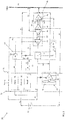
- FIG. 1 a schematic diagram of a portion of an environment control system (ECS) 20, such as a pack for example, is depicted according to non-limiting embodiments.
- ECS environment control system
- the system 20 can receive a first medium A1 at a first inlet 22.
- the first medium A1 is bleed air, which is pressurized air originating from i.e. being "bled" from, an engine or auxiliary power unit of the aircraft. It shall be understood that one or more of the temperature, humidity, and pressure of the bleed air can vary based upon the compressor stage and revolutions per minute of the engine or auxiliary power unit from which the air is drawn.
- the system 20 also receives a second medium A2 at an inlet 24 and may provide a conditioned form of at least one of the first medium A1 and the second medium A2 to a volume 26.
- the second medium A2 is fresh air, such as outside air for example.
- the outside air can be procured via one or more scooping mechanisms, such as an impact scoop or a flush scoop for example.
- the inlet 24 can be considered a fresh or outside air inlet.
- the fresh air A2 described herein is at an ambient pressure equal to an air pressure outside of the aircraft when the aircraft is on the ground, and is between an ambient pressure and a cabin pressure when the aircraft is in flight.
- the system 20 can further receive a third medium A3 from the volume 26.
- the volume 26 is the cabin of an aircraft and the third medium A3 is cabin discharge air, which is air leaving the volume 26 that would typically be discharged overboard.
- the system 20 is configured to extract work from the third medium A3. In this manner, the pressurized air A3 of the volume 26 can be utilized by the system 20 to achieve certain operations.
- the environmental control system 20 includes a RAM air circuit 30 including a shell or duct, illustrated schematically at 32, within which one or more heat exchangers are located.
- the shell 32 can receive and direct a medium, such as ram air for example, through a portion of the system 20.
- the one or more heat exchangers are devices built for efficient heat transfer from one medium to another. Examples of the type of heat exchangers that may be used, include, but are not limited to, double pipe, shell and tube, plate, plate and shell, adiabatic shell, plate fin, pillow plate, and fluid heat exchangers.
- the one or more heat exchangers arranged within the shell 32 may be referred to as ram heat exchangers.
- the ram heat exchangers include a first heat exchanger 34, a second heat exchanger 36, and a third heat exchanger 38.
- ram air such as outside air for example, acts as a heat sink to cool a medium passing there through, for example the first medium A1 and/or the second medium A2.
- the system 20 additionally comprises at least one compression device 40.
- the compression device 40 of the system 20 is a mechanical device that includes components for performing thermodynamic work on a medium (e.g., extracts work from or applies work to the first medium A1, the second medium A2, and/or the third medium A3 by raising and/or lowering pressure and by raising and/or lowering temperature).
- Examples of the compression device 40 include an air cycle machine, a three-wheel air cycle machine, a four-wheel air cycle machine, etc.
- the compression device 40 includes a compressor 42, a bleed air turbine 44, a fresh air turbine 46, and a power turbine 48 operably coupled to each other via a shaft 50.
- the compressor 42 is a mechanical device that raises a pressure of a medium and can be driven by another mechanical device (e.g., a motor or a medium via a turbine). Examples of compressor types include centrifugal, diagonal or mixed-flow, axial-flow, reciprocating, ionic liquid piston, rotary screw, rotary vane, scroll, diaphragm, air bubble, etc.
- the compressor 42 is configured to receive and pressurize the second medium A2.
- the bleed air turbine 44, the fresh air turbine 46, and the power turbine 48 are mechanical devices that expand a medium and extract work therefrom (also referred to as extracting energy).
- the turbines 44, 46, and 48 drive the compressor 42 via the shaft 50.
- the system 20 additionally comprises at least one expansion device 52.
- the expansion device 52 is a mechanical device, similar to the compression device 40, and includes components for performing thermodynamic work on a medium (e.g., extracts work from or applies work to the first medium A1 by raising and/or lowering pressure and by raising and/or lowering temperature). Examples of the expansion device 52 include, but are not limited to, a simple air cycle machine or a tip turbine fan etc.
- the expansion device 52 is a two-wheel air cycle machine including a turbine 54 and a fan 56 operably coupled via a shaft 58.
- the turbine 54 is a mechanical device that expands a medium and extracts work therefrom.
- the turbine 54 drives rotation of the fan 56 via the shaft 58.
- the turbine 54 can comprise a nozzle configured to accelerate a medium supplied thereto for entry into a turbine impeller (not shown).
- the fan 56 is a mechanical device that can force via push or pull methods a medium (e.g., ram air) through the shell 32 across the one or more ram heat exchangers 34, 36, 38 and at a variable cooling to control temperatures.
- the system 20 additionally includes at least one dehumidification system 60.
- the dehumidification system 60 includes a condenser 62 arranged in fluid communication with both the first medium A1 and the second medium A2, and a water extractor or collector 64 associated with each of the first medium A1 and the second medium A2.
- the condenser 62 is a particular type of heat exchanger and the water collectors 64 are mechanical devices that perform a process of removing water from a medium.
- the configuration of the at least one dehumidification system 60 may vary. For example, in the embodiment illustrated in FIGS.
- the system 20 includes a first dehumidification system 60a having a condenser 62a and a water extractor 64a located directly downstream from the condenser 62a.
- the system 20 additionally includes a second dehumidification system 60b having a condenser 62b and a water extractor 64b located directly downstream from the condenser 62b.
- the first dehumidification system 60a is arranged within the fluid flow path of the first medium A1 and the second dehumidification system 60b is arranged within the fluid flow path of the second medium A2
- the condensers of both dehumidification systems provide an interface for the first and second mediums.
- various configurations of the one or more dehumidification systems 60 are considered within the scope of the disclosure.
- Valves e.g., flow regulation device or mass flow valve
- Valves are devices that regulate, direct, and/or control a flow of a medium by opening, closing, or partially obstructing various passageways within the tubes, pipes, etc. of the system.
- Valves can be operated by actuators, such that flow rates of the medium in any portion of the system 20 can be regulated to a desired value.
- a first valve V1 is configured to control a supply of the first medium A1 to the system 20.
- a second valve V2 may be operable to allow a portion of a medium to bypass the expansion device 52, and a third valve V3 may be operable to control a flow of the first medium A1 to the inlet of the compressor 42.
- Operation of a fourth valve V4 allows a medium to selectively bypass the compression device 40 and a fifth valve V5 is configured to control a supply of a first medium A1 mixed with the second medium A2.
- Valve V6 may be configured to control a supply of the third medium A3 to the system 20, and the valve V7 is operable to control a flow of the first medium A1 provided to the ram air circuit 30.
- the system 20 is operable in a plurality of modes, selectable based on a flight condition of the aircraft.
- the system 20 is operable in a first mode when the aircraft is on the ground or at a low altitude.
- the system 20 may be operable in a second mode when the aircraft is on the ground, such as during hot humid days for example, or at low altitude.
- the system is operable in a third mode when the aircraft is in flight, such as high altitude cruise, climb, and/or descent, and is operable in a fourth mode when 100% fresh air is to be provided to the volume 26 for example.
- valve V6 for controlling a supply of the third medium A3 to the system 20 may, but need not be open. Accordingly, the supply of third medium A3 is not critical to operation of the system 20 in the first mode.
- each of valves V2, V5, and V7 is in a closed configuration.
- valve V3 may be arranged in either an open or a closed configuration.
- Valve V1 is open and the first medium A1 drawn through the inlet port 22 may pass through an ozone converter, illustrated at 70, before being provided to the first heat exchanger 34.
- the first medium A1 is cooled via a flow of ram air.
- the first medium A1 then passes from the first heat exchanger 34 to the third heat exchanger 38 within the series of ram heat exchangers where the moisture within the first medium A1 condenses.
- Moisture is removed from the wet first medium A1 within a water extractor 64 of the dehumidification system 60 before being provided to the inlet of the bleed air turbine 44.
- the first medium A1 is expanded and work is extracted, to power operation of the compressor 42.
- the first medium A1 output from the bleed air turbine 44 is provided to a condenser 62 where the first medium A1 is arranged in a heat exchange relationship with the second medium A2. Within the condenser 62, the cool first medium A1 is heated. The resulting warm first medium A1 is then provided to the turbine 54 of the expansion device 52. Within the turbine 54, the first medium A1 is expanded and work is extracted, thereby driving operation of the fan 56 which moves ram air through the ram air circuit 30. The first medium A1 output from the turbine 54 of the expansion device 52 may then be directed to one or more loads of the system 20. Accordingly, in the first mode of operation, the first medium A1 is provided through the bleed air turbine 44 of the compression device 40 and the bleed air turbine 54 of the expansion device in series.
- a supply of second medium A2 drawn from port 24 is compressed within the compressor 42 causing the temperature of the second medium A2 to increase.
- the second medium A2 output from the compressor 42 passes sequentially through an ozone converter 72 and the second heat exchanger 36 to cool the second medium A2 to about an ambient temperature.
- the compressed second medium A2 output from the second heat exchanger 36 is provided to the condenser 62 and then to a water extractor 64 to condense and remove moisture therefrom. Moisture is removed from the second medium A2 when the second medium is at a temperature above freezing.
- the temperature of the second medium is between about 40°C and about 50°C when the second medium A2 is provided to the condenser 62 and the water extractor 64.
- the cool second medium A2 having a medium pressure is then provided to the fresh air turbine 46 of the compression device 40 where it is expanded and work is extracted, thereby driving operation of the compressor 42.
- the second medium A2 output from the turbine 46 of the compression device 40 is combined with the first medium A1 output from the turbine 54 of the expansion device 52 before being sent to one or more loads, including the volume 26.
- the second mode of operation of the system of FIG. 1 is similar to the first mode; however, in the second mode of operation, valve V3 is open.
- valve V3 is open.
- at least a portion of the first medium A1 output from the bleed air turbine 54 of the expansion device 52 is mixed with the second medium A2 upstream from the inlet of the compressor 42.
- Mixing the first medium A1 output from the bleed air turbine 54 of the expansion device 52 with the second medium A2 upstream from the compressor 42 lowers the temperature of the air at the compressor inlet, thereby allowing the compressor 42 to achieve a higher discharge pressure.
- mixing the first medium A1 output from the bleed air turbine 54 of the expansion device 52 with the second medium A2 upstream from the compressor 42 lowers the humidity of the second medium A2, thereby reducing the heat load of the system 20.
- the first medium A1 is drawn through the inlet port 22 and passes through the ozone converter 70 before being provided to the first heat exchanger 34. From the first heat exchanger 34, the first medium A1 is provided to the third heat exchanger 38 where the moisture within the first medium A1 condenses. Moisture is removed from the wet first medium A1 within the water extractor 64 before being provided to the inlet of the bleed air turbine 44 of the compressing device 40. Within the turbine 44, the first medium A1 is expanded and work is extracted, to power operation of the compressor 42. From the turbine 44, the first medium A1 is provided to the condenser 62. In the third mode of operation, valve V2 is open.
- the first medium A1 output from the condenser 62 flows through the conduit including valve V2, thereby bypassing the expansion device 52. Accordingly, the first medium A1 output from the condenser 62 is directed to one or more loads of the system 20.
- the expansion device 52 is non-operational in the third mode.
- the system 20 is typically in the third mode when the aircraft is in flight (at altitude), the forward movement of the aircraft is sufficient to draw ram air through the ram air circuit 30 without the use of the fan 56.
- the second medium A2 is compressed within the compressor 42 causing the temperature of the second medium A2 to increase.
- the second medium A2 output from the compressor 42 passes sequentially through the ozone converter 72 and the second heat exchanger 36 to cool the second medium A2 to about an ambient temperature.
- the compressed second medium A2 output from the second heat exchanger 36 is provided to the condenser 62 and then to a water extractor 64 to condense and remove moisture therefrom.
- the cool second medium A2 having a medium pressure is then provided to the fresh air turbine 46 of the compression device 40 where it is expanded and work is extracted, thereby driving operation of the compressor 42.
- the second medium A2 output from the turbine 46 of the compression device 40 is combined with the first medium A1 output from the turbine 54 of the expansion device 52 before being sent to one or more loads, including the volume 26.
- valve V6 is open to provide the third medium A3 to the system 20.
- the third medium A3 is supplied to the power turbine 48 of the compression device 40. Within the turbine 48, the third medium A3 is expanded and work is extracted, to provide additional energy for operation of the compressor 42.
- the third medium A3 output from the power turbine 48 may be provided to a downstream portion of the system 20.
- the third medium A3 is directed to an inlet of the ram air circuit 30, where it is combined with the ram air before flowing across the ram air heat exchangers 34, 36, 38.
- a fourth mode of operation referred to as a "100% Fresh Air" mode
- the second medium A2 is provided to the volume 26 or other loads.
- valve V2 is closed and valve V7 is open.
- the first medium A1 output from the bleed air turbine 44 of the compression device 40 passes through the compressor before being directed to a downstream portion of the system 20.
- valve V7 is open, the first medium A1 is not provided to the expansion device 52. Rather, the first medium A1 is directed to an inlet of the ram air circuit 30, where it is combined with the ram air before flowing across the ram air heat exchangers 34, 36, 38.
Landscapes
- Health & Medical Sciences (AREA)
- General Health & Medical Sciences (AREA)
- Pulmonology (AREA)
- Engineering & Computer Science (AREA)
- Aviation & Aerospace Engineering (AREA)
- Structures Of Non-Positive Displacement Pumps (AREA)
- Control Of Turbines (AREA)
- Drying Of Gases (AREA)
Applications Claiming Priority (1)
| Application Number | Priority Date | Filing Date | Title |
|---|---|---|---|
| US201762581959P | 2017-11-06 | 2017-11-06 |
Publications (3)
| Publication Number | Publication Date |
|---|---|
| EP3489142A2 true EP3489142A2 (de) | 2019-05-29 |
| EP3489142A3 EP3489142A3 (de) | 2019-08-14 |
| EP3489142B1 EP3489142B1 (de) | 2021-12-29 |
Family
ID=64267490
Family Applications (1)
| Application Number | Title | Priority Date | Filing Date |
|---|---|---|---|
| EP18204552.6A Active EP3489142B1 (de) | 2017-11-06 | 2018-11-06 | Flugzeugumweltkontrollsystem mit zapfluftturbinen in reihe |
Country Status (2)
| Country | Link |
|---|---|
| US (1) | US11136130B2 (de) |
| EP (1) | EP3489142B1 (de) |
Cited By (5)
| Publication number | Priority date | Publication date | Assignee | Title |
|---|---|---|---|---|
| US11053010B2 (en) | 2018-01-19 | 2021-07-06 | Hamilton Sunstrand Corporation | Aircraft environmental control system |
| EP3945026A1 (de) * | 2020-07-30 | 2022-02-02 | Hamilton Sundstrand Corporation | Flugzeugklimaregelungssystem |
| EP4273044A1 (de) * | 2022-05-02 | 2023-11-08 | Hamilton Sundstrand Corporation | 100% umgebungsluft-umweltsteuersystem |
| US11840344B2 (en) | 2020-07-30 | 2023-12-12 | Hamilton Sundstrand Corporation | Aircraft environmental control system |
| US11878800B2 (en) | 2020-07-30 | 2024-01-23 | Hamilton Sundstrand Corporation | Aircraft environmental control system |
Families Citing this family (14)
| Publication number | Priority date | Publication date | Assignee | Title |
|---|---|---|---|---|
| US11192655B2 (en) * | 2017-11-03 | 2021-12-07 | Hamilton Sundstrand Corporation | Regenerative system ECOECS |
| DE102018126921A1 (de) * | 2018-10-29 | 2020-04-30 | Airbus Operations Gmbh | Flugzeugkälteanlage mit einer motor-unterstützten Kabinenabluftturbine |
| FR3093325B1 (fr) * | 2019-03-01 | 2021-02-12 | Liebherr Aerospace Toulouse Sas | Système de conditionnement d’air d’une cabine d’aéronef comprenant des moyens de réchauffage de l’eau récoltée par la boucle d’extraction d’eau |
| US11332252B2 (en) | 2019-06-11 | 2022-05-17 | Hamilton Sundstrand Corporation | Using bleed air to supply outside air to a cabin |
| US11377217B2 (en) | 2019-06-11 | 2022-07-05 | Hamilton Sundstrand Corporation | Using bleed air to supply outside air to a cabin |
| FR3097529B1 (fr) | 2019-06-21 | 2021-06-18 | Liebherr Aerospace Toulouse Sas | Système de conditionnement d’air électrique d’une cabine d’aéronef comprenant un motocompresseur et une turbomachine à cycle à air |
| FR3103140B1 (fr) * | 2019-11-19 | 2021-10-22 | Liebherr Aerospace Toulouse Sas | Système de conditionnement d’air d’une cabine d’un véhicule de transport aérien ou ferroviaire utilisant une source d’air pneumatique et thermique distincte de la source d’air de conditionnement |
| EP3845455B1 (de) * | 2019-12-31 | 2023-04-19 | Hamilton Sundstrand Corporation | Flugzeugklimaanlage |
| US12139260B2 (en) * | 2021-01-29 | 2024-11-12 | Hamilton Sundstrand Corporation | Ambient air architecture with single ACM without an ambient turbine |
| US11926422B2 (en) | 2021-04-29 | 2024-03-12 | Hamilton Sundstrand Corporation | 100% ambient air environmental control system with bleed turbine in series |
| US11781441B2 (en) | 2021-12-30 | 2023-10-10 | Hamilton Sundstrand Corporation | Air cycle machine with separate compressor and turbine and fan and turbine |
| US12054265B2 (en) * | 2022-03-23 | 2024-08-06 | Hamilton Sundstrand Corporation | Electric motor driven air cycle environmental control system |
| US12528589B2 (en) * | 2022-08-04 | 2026-01-20 | Hamilton Sundstrand Corporation | RAM air cooling power recovery |
| US20250074601A1 (en) * | 2023-09-05 | 2025-03-06 | Hamilton Sundstrand Corporation | Less bleed environmental control system |
Family Cites Families (20)
| Publication number | Priority date | Publication date | Assignee | Title |
|---|---|---|---|---|
| US5299763A (en) * | 1991-12-23 | 1994-04-05 | Allied-Signal Inc. | Aircraft cabin air conditioning system with improved fresh air supply |
| US5461882A (en) * | 1994-07-22 | 1995-10-31 | United Technologies Corporation | Regenerative condensing cycle |
| DE19963280C1 (de) | 1999-12-27 | 2001-08-23 | Liebherr Aerospace Gmbh | Klimatisierungssystem für Flugzeugkabinen |
| DE10036443A1 (de) * | 2000-07-26 | 2002-04-04 | Liebherr Aerospace Gmbh | Klimatisierungssystem für Flugzeuge |
| DE10047623C1 (de) | 2000-09-26 | 2002-05-23 | Liebherr Aerospace Gmbh | Klimatisierungssystem für Flugzeuge |
| DE10234968A1 (de) | 2002-07-31 | 2004-02-12 | Liebherr-Aerospace Lindenberg Gmbh | Flugzeugklimaanlage |
| GB0414341D0 (en) * | 2004-06-26 | 2004-07-28 | Honeywell Normalair Garrett | Closed loop air conditioning system |
| DE102006042584B4 (de) * | 2006-09-11 | 2008-11-20 | Airbus Deutschland Gmbh | Luftzufuhrsystem eines Flugzeuges sowie Verfahren zum Vermischen zweier Luftströme in einem Luftzufuhrsystem |
| US9003814B2 (en) * | 2011-11-11 | 2015-04-14 | Hamilton Sundstrand Corporation | Turbo air compressor with pressure recovery |
| US9669936B1 (en) * | 2012-10-24 | 2017-06-06 | The Boeing Company | Aircraft air conditioning systems and methods |
| EP2998223B1 (de) * | 2014-09-19 | 2018-12-05 | Airbus Operations GmbH | Flugzeugklimaanlage und Verfahren für den Betrieb einer Flugzeugklimaanlage |
| US10144519B2 (en) * | 2014-10-24 | 2018-12-04 | United Technologies Corporation | Compressor bleed air supply for an aircraft environmental control system |
| US9657648B2 (en) * | 2014-11-25 | 2017-05-23 | Hamilton Sundstrand Corporation | Environmental air conditioning system |
| US10160546B2 (en) * | 2015-03-20 | 2018-12-25 | Hamilton Sundstrand Corporation | Air cycle machine with cooling air flow path |
| EP3176089B1 (de) * | 2015-12-02 | 2019-02-06 | Airbus Operations GmbH | Kabinenluftsteuerungssystem für ein flugzeug |
| EP3184429A1 (de) * | 2015-12-21 | 2017-06-28 | Airbus Operations, S.L. | Flugzeug mit hybrider druckluftversorgung |
| DE102016204911A1 (de) * | 2016-03-24 | 2017-09-28 | Airbus Operations Gmbh | Flugzeugklimaanlage mit einem elektrisch angetriebenen Umgebungsluftkompressor und Verfahren zum Betreiben einer derartigen Flugzeugklimaanlage |
| US10850853B2 (en) | 2016-04-22 | 2020-12-01 | Hamilton Sunstrand Corporation | Environmental control system utilizing bleed pressure assist |
| US10829226B2 (en) * | 2016-05-24 | 2020-11-10 | Textron Innovations, Inc. | Compressor temperature control system and method |
| EP3248877B1 (de) * | 2016-05-26 | 2023-05-10 | Hamilton Sundstrand Corporation | Mischen von neben- und stauluft an einem turbineneinlass |
-
2018
- 2018-05-23 US US15/987,651 patent/US11136130B2/en active Active
- 2018-11-06 EP EP18204552.6A patent/EP3489142B1/de active Active
Non-Patent Citations (1)
| Title |
|---|
| None |
Cited By (11)
| Publication number | Priority date | Publication date | Assignee | Title |
|---|---|---|---|---|
| US11053010B2 (en) | 2018-01-19 | 2021-07-06 | Hamilton Sunstrand Corporation | Aircraft environmental control system |
| EP3514065B1 (de) * | 2018-01-19 | 2023-01-18 | Hamilton Sundstrand Corporation | Umweltkontrollsystem für flugzeug |
| EP3945026A1 (de) * | 2020-07-30 | 2022-02-02 | Hamilton Sundstrand Corporation | Flugzeugklimaregelungssystem |
| US11840344B2 (en) | 2020-07-30 | 2023-12-12 | Hamilton Sundstrand Corporation | Aircraft environmental control system |
| US11878800B2 (en) | 2020-07-30 | 2024-01-23 | Hamilton Sundstrand Corporation | Aircraft environmental control system |
| US11939065B2 (en) | 2020-07-30 | 2024-03-26 | Hamilton Sundstrand Corporation | Aircraft environmental control system |
| US11999491B2 (en) | 2020-07-30 | 2024-06-04 | Hamilton Sundstrand Corporation | Aircraft environmental control system |
| US12097962B2 (en) | 2020-07-30 | 2024-09-24 | Hamilton Sundstrand Corporation | Aircraft environmental control system |
| US12214888B2 (en) | 2020-07-30 | 2025-02-04 | Hamilton Sundstrand Corporation | Aircraft environmental control system |
| EP4273044A1 (de) * | 2022-05-02 | 2023-11-08 | Hamilton Sundstrand Corporation | 100% umgebungsluft-umweltsteuersystem |
| US12595065B2 (en) | 2022-05-02 | 2026-04-07 | Hamilton Sundstrand Corporation | 100% ambient air environmental control system |
Also Published As
| Publication number | Publication date |
|---|---|
| US11136130B2 (en) | 2021-10-05 |
| EP3489142A3 (de) | 2019-08-14 |
| US20190135440A1 (en) | 2019-05-09 |
| EP3489142B1 (de) | 2021-12-29 |
Similar Documents
| Publication | Publication Date | Title |
|---|---|---|
| EP3489142B1 (de) | Flugzeugumweltkontrollsystem mit zapfluftturbinen in reihe | |
| EP3514065B1 (de) | Umweltkontrollsystem für flugzeug | |
| EP3480113B1 (de) | Regeneratives system ecoecs | |
| EP3354573B1 (de) | Klimaregelungssystem in einer integrierten aggregatsanordnung mit einem zapfluft/kabinenabluft-wärmetauscher | |
| EP3760542B1 (de) | Umgebungsluftregelsystem eines flugzeugs | |
| EP3354576B1 (de) | Fortschrittliches umweltkontrollsystem in einer integrierten geteilten anordnung mit einem zapfluft wärmeübertrager | |
| EP3945030B1 (de) | Flugzeugklimaregelungssystem | |
| EP3587269A1 (de) | Flugzeugumgebungskontrollsystem | |
| EP3750808B1 (de) | Verwendung von zapfluft zur zuführung von aussenluft zu einer kabine | |
| EP3354574B1 (de) | Klimaregelungssystem in einer integrierten aggregatsanordnung mit zwei zapfluft/kabinenabluft-wärmetauschern | |
| EP3750809A1 (de) | Verwendung von zapfluft zur zuführung von aussenluft zu einer kabine | |
| EP4005925A1 (de) | Raumluftarchitektur mit einzelluftkreislaufmaschine und hochdruckwasserabscheider | |
| EP3882153A1 (de) | Frischluft-ecs | |
| EP3712070A1 (de) | Shoestring-umweltsteuersystem für ein flugzeug | |
| EP4331991A1 (de) | Klimaregelungssystem mit niedrigem einlassdruck | |
| EP4520664A1 (de) | Umweltkontrollsystem mit verringertem ablass | |
| US12234018B2 (en) | Environmental control system with no bleed driven throttle | |
| US20260103285A1 (en) | Series turbine simple cycle with integrated flow multiplier | |
| US20250026479A1 (en) | Environmental control system with adaptive turbine arrangement | |
| US20250282482A1 (en) | Environmental control system using architecture with dual entry turbine | |
| CA2992857C (en) | Advanced environmental control system in an integrated pack arrangement with one bleed/outflow heat exchanger |
Legal Events
| Date | Code | Title | Description |
|---|---|---|---|
| PUAI | Public reference made under article 153(3) epc to a published international application that has entered the european phase |
Free format text: ORIGINAL CODE: 0009012 |
|
| STAA | Information on the status of an ep patent application or granted ep patent |
Free format text: STATUS: THE APPLICATION HAS BEEN PUBLISHED |
|
| AK | Designated contracting states |
Kind code of ref document: A2 Designated state(s): AL AT BE BG CH CY CZ DE DK EE ES FI FR GB GR HR HU IE IS IT LI LT LU LV MC MK MT NL NO PL PT RO RS SE SI SK SM TR |
|
| AX | Request for extension of the european patent |
Extension state: BA ME |
|
| PUAL | Search report despatched |
Free format text: ORIGINAL CODE: 0009013 |
|
| RIC1 | Information provided on ipc code assigned before grant |
Ipc: B64D 13/06 20060101AFI20190704BHEP |
|
| AK | Designated contracting states |
Kind code of ref document: A3 Designated state(s): AL AT BE BG CH CY CZ DE DK EE ES FI FR GB GR HR HU IE IS IT LI LT LU LV MC MK MT NL NO PL PT RO RS SE SI SK SM TR |
|
| AX | Request for extension of the european patent |
Extension state: BA ME |
|
| STAA | Information on the status of an ep patent application or granted ep patent |
Free format text: STATUS: REQUEST FOR EXAMINATION WAS MADE |
|
| 17P | Request for examination filed |
Effective date: 20191126 |
|
| RBV | Designated contracting states (corrected) |
Designated state(s): AL AT BE BG CH CY CZ DE DK EE ES FI FR GB GR HR HU IE IS IT LI LT LU LV MC MK MT NL NO PL PT RO RS SE SI SK SM TR |
|
| STAA | Information on the status of an ep patent application or granted ep patent |
Free format text: STATUS: EXAMINATION IS IN PROGRESS |
|
| 17Q | First examination report despatched |
Effective date: 20200528 |
|
| GRAP | Despatch of communication of intention to grant a patent |
Free format text: ORIGINAL CODE: EPIDOSNIGR1 |
|
| STAA | Information on the status of an ep patent application or granted ep patent |
Free format text: STATUS: GRANT OF PATENT IS INTENDED |
|
| INTG | Intention to grant announced |
Effective date: 20210615 |
|
| GRAS | Grant fee paid |
Free format text: ORIGINAL CODE: EPIDOSNIGR3 |
|
| GRAA | (expected) grant |
Free format text: ORIGINAL CODE: 0009210 |
|
| STAA | Information on the status of an ep patent application or granted ep patent |
Free format text: STATUS: THE PATENT HAS BEEN GRANTED |
|
| AK | Designated contracting states |
Kind code of ref document: B1 Designated state(s): AL AT BE BG CH CY CZ DE DK EE ES FI FR GB GR HR HU IE IS IT LI LT LU LV MC MK MT NL NO PL PT RO RS SE SI SK SM TR |
|
| REG | Reference to a national code |
Ref country code: GB Ref legal event code: FG4D |
|
| REG | Reference to a national code |
Ref country code: CH Ref legal event code: EP |
|
| REG | Reference to a national code |
Ref country code: AT Ref legal event code: REF Ref document number: 1458518 Country of ref document: AT Kind code of ref document: T Effective date: 20220115 |
|
| REG | Reference to a national code |
Ref country code: IE Ref legal event code: FG4D |
|
| REG | Reference to a national code |
Ref country code: DE Ref legal event code: R096 Ref document number: 602018028734 Country of ref document: DE |
|
| REG | Reference to a national code |
Ref country code: LT Ref legal event code: MG9D |
|
| PG25 | Lapsed in a contracting state [announced via postgrant information from national office to epo] |
Ref country code: RS Free format text: LAPSE BECAUSE OF FAILURE TO SUBMIT A TRANSLATION OF THE DESCRIPTION OR TO PAY THE FEE WITHIN THE PRESCRIBED TIME-LIMIT Effective date: 20211229 Ref country code: LT Free format text: LAPSE BECAUSE OF FAILURE TO SUBMIT A TRANSLATION OF THE DESCRIPTION OR TO PAY THE FEE WITHIN THE PRESCRIBED TIME-LIMIT Effective date: 20211229 Ref country code: FI Free format text: LAPSE BECAUSE OF FAILURE TO SUBMIT A TRANSLATION OF THE DESCRIPTION OR TO PAY THE FEE WITHIN THE PRESCRIBED TIME-LIMIT Effective date: 20211229 Ref country code: BG Free format text: LAPSE BECAUSE OF FAILURE TO SUBMIT A TRANSLATION OF THE DESCRIPTION OR TO PAY THE FEE WITHIN THE PRESCRIBED TIME-LIMIT Effective date: 20220329 |
|
| REG | Reference to a national code |
Ref country code: NL Ref legal event code: MP Effective date: 20211229 |
|
| REG | Reference to a national code |
Ref country code: AT Ref legal event code: MK05 Ref document number: 1458518 Country of ref document: AT Kind code of ref document: T Effective date: 20211229 |
|
| PG25 | Lapsed in a contracting state [announced via postgrant information from national office to epo] |
Ref country code: SE Free format text: LAPSE BECAUSE OF FAILURE TO SUBMIT A TRANSLATION OF THE DESCRIPTION OR TO PAY THE FEE WITHIN THE PRESCRIBED TIME-LIMIT Effective date: 20211229 Ref country code: NO Free format text: LAPSE BECAUSE OF FAILURE TO SUBMIT A TRANSLATION OF THE DESCRIPTION OR TO PAY THE FEE WITHIN THE PRESCRIBED TIME-LIMIT Effective date: 20220329 Ref country code: LV Free format text: LAPSE BECAUSE OF FAILURE TO SUBMIT A TRANSLATION OF THE DESCRIPTION OR TO PAY THE FEE WITHIN THE PRESCRIBED TIME-LIMIT Effective date: 20211229 Ref country code: HR Free format text: LAPSE BECAUSE OF FAILURE TO SUBMIT A TRANSLATION OF THE DESCRIPTION OR TO PAY THE FEE WITHIN THE PRESCRIBED TIME-LIMIT Effective date: 20211229 Ref country code: GR Free format text: LAPSE BECAUSE OF FAILURE TO SUBMIT A TRANSLATION OF THE DESCRIPTION OR TO PAY THE FEE WITHIN THE PRESCRIBED TIME-LIMIT Effective date: 20220330 |
|
| PG25 | Lapsed in a contracting state [announced via postgrant information from national office to epo] |
Ref country code: NL Free format text: LAPSE BECAUSE OF FAILURE TO SUBMIT A TRANSLATION OF THE DESCRIPTION OR TO PAY THE FEE WITHIN THE PRESCRIBED TIME-LIMIT Effective date: 20211229 |
|
| PG25 | Lapsed in a contracting state [announced via postgrant information from national office to epo] |
Ref country code: SM Free format text: LAPSE BECAUSE OF FAILURE TO SUBMIT A TRANSLATION OF THE DESCRIPTION OR TO PAY THE FEE WITHIN THE PRESCRIBED TIME-LIMIT Effective date: 20211229 Ref country code: SK Free format text: LAPSE BECAUSE OF FAILURE TO SUBMIT A TRANSLATION OF THE DESCRIPTION OR TO PAY THE FEE WITHIN THE PRESCRIBED TIME-LIMIT Effective date: 20211229 Ref country code: RO Free format text: LAPSE BECAUSE OF FAILURE TO SUBMIT A TRANSLATION OF THE DESCRIPTION OR TO PAY THE FEE WITHIN THE PRESCRIBED TIME-LIMIT Effective date: 20211229 Ref country code: PT Free format text: LAPSE BECAUSE OF FAILURE TO SUBMIT A TRANSLATION OF THE DESCRIPTION OR TO PAY THE FEE WITHIN THE PRESCRIBED TIME-LIMIT Effective date: 20220429 Ref country code: ES Free format text: LAPSE BECAUSE OF FAILURE TO SUBMIT A TRANSLATION OF THE DESCRIPTION OR TO PAY THE FEE WITHIN THE PRESCRIBED TIME-LIMIT Effective date: 20211229 Ref country code: EE Free format text: LAPSE BECAUSE OF FAILURE TO SUBMIT A TRANSLATION OF THE DESCRIPTION OR TO PAY THE FEE WITHIN THE PRESCRIBED TIME-LIMIT Effective date: 20211229 Ref country code: CZ Free format text: LAPSE BECAUSE OF FAILURE TO SUBMIT A TRANSLATION OF THE DESCRIPTION OR TO PAY THE FEE WITHIN THE PRESCRIBED TIME-LIMIT Effective date: 20211229 |
|
| PG25 | Lapsed in a contracting state [announced via postgrant information from national office to epo] |
Ref country code: PL Free format text: LAPSE BECAUSE OF FAILURE TO SUBMIT A TRANSLATION OF THE DESCRIPTION OR TO PAY THE FEE WITHIN THE PRESCRIBED TIME-LIMIT Effective date: 20211229 Ref country code: AT Free format text: LAPSE BECAUSE OF FAILURE TO SUBMIT A TRANSLATION OF THE DESCRIPTION OR TO PAY THE FEE WITHIN THE PRESCRIBED TIME-LIMIT Effective date: 20211229 |
|
| PG25 | Lapsed in a contracting state [announced via postgrant information from national office to epo] |
Ref country code: IS Free format text: LAPSE BECAUSE OF FAILURE TO SUBMIT A TRANSLATION OF THE DESCRIPTION OR TO PAY THE FEE WITHIN THE PRESCRIBED TIME-LIMIT Effective date: 20220429 |
|
| REG | Reference to a national code |
Ref country code: DE Ref legal event code: R097 Ref document number: 602018028734 Country of ref document: DE |
|
| PG25 | Lapsed in a contracting state [announced via postgrant information from national office to epo] |
Ref country code: DK Free format text: LAPSE BECAUSE OF FAILURE TO SUBMIT A TRANSLATION OF THE DESCRIPTION OR TO PAY THE FEE WITHIN THE PRESCRIBED TIME-LIMIT Effective date: 20211229 Ref country code: AL Free format text: LAPSE BECAUSE OF FAILURE TO SUBMIT A TRANSLATION OF THE DESCRIPTION OR TO PAY THE FEE WITHIN THE PRESCRIBED TIME-LIMIT Effective date: 20211229 |
|
| PLBE | No opposition filed within time limit |
Free format text: ORIGINAL CODE: 0009261 |
|
| STAA | Information on the status of an ep patent application or granted ep patent |
Free format text: STATUS: NO OPPOSITION FILED WITHIN TIME LIMIT |
|
| 26N | No opposition filed |
Effective date: 20220930 |
|
| PG25 | Lapsed in a contracting state [announced via postgrant information from national office to epo] |
Ref country code: SI Free format text: LAPSE BECAUSE OF FAILURE TO SUBMIT A TRANSLATION OF THE DESCRIPTION OR TO PAY THE FEE WITHIN THE PRESCRIBED TIME-LIMIT Effective date: 20211229 |
|
| PG25 | Lapsed in a contracting state [announced via postgrant information from national office to epo] |
Ref country code: IT Free format text: LAPSE BECAUSE OF FAILURE TO SUBMIT A TRANSLATION OF THE DESCRIPTION OR TO PAY THE FEE WITHIN THE PRESCRIBED TIME-LIMIT Effective date: 20211229 |
|
| P01 | Opt-out of the competence of the unified patent court (upc) registered |
Effective date: 20230522 |
|
| PG25 | Lapsed in a contracting state [announced via postgrant information from national office to epo] |
Ref country code: MC Free format text: LAPSE BECAUSE OF FAILURE TO SUBMIT A TRANSLATION OF THE DESCRIPTION OR TO PAY THE FEE WITHIN THE PRESCRIBED TIME-LIMIT Effective date: 20211229 |
|
| REG | Reference to a national code |
Ref country code: CH Ref legal event code: PL |
|
| REG | Reference to a national code |
Ref country code: BE Ref legal event code: MM Effective date: 20221130 |
|
| PG25 | Lapsed in a contracting state [announced via postgrant information from national office to epo] |
Ref country code: LI Free format text: LAPSE BECAUSE OF NON-PAYMENT OF DUE FEES Effective date: 20221130 Ref country code: CH Free format text: LAPSE BECAUSE OF NON-PAYMENT OF DUE FEES Effective date: 20221130 |
|
| PG25 | Lapsed in a contracting state [announced via postgrant information from national office to epo] |
Ref country code: LU Free format text: LAPSE BECAUSE OF NON-PAYMENT OF DUE FEES Effective date: 20221106 |
|
| PG25 | Lapsed in a contracting state [announced via postgrant information from national office to epo] |
Ref country code: IE Free format text: LAPSE BECAUSE OF NON-PAYMENT OF DUE FEES Effective date: 20221106 |
|
| PG25 | Lapsed in a contracting state [announced via postgrant information from national office to epo] |
Ref country code: BE Free format text: LAPSE BECAUSE OF NON-PAYMENT OF DUE FEES Effective date: 20221130 |
|
| PG25 | Lapsed in a contracting state [announced via postgrant information from national office to epo] |
Ref country code: HU Free format text: LAPSE BECAUSE OF FAILURE TO SUBMIT A TRANSLATION OF THE DESCRIPTION OR TO PAY THE FEE WITHIN THE PRESCRIBED TIME-LIMIT; INVALID AB INITIO Effective date: 20181106 |
|
| PG25 | Lapsed in a contracting state [announced via postgrant information from national office to epo] |
Ref country code: CY Free format text: LAPSE BECAUSE OF FAILURE TO SUBMIT A TRANSLATION OF THE DESCRIPTION OR TO PAY THE FEE WITHIN THE PRESCRIBED TIME-LIMIT Effective date: 20211229 |
|
| PG25 | Lapsed in a contracting state [announced via postgrant information from national office to epo] |
Ref country code: MK Free format text: LAPSE BECAUSE OF FAILURE TO SUBMIT A TRANSLATION OF THE DESCRIPTION OR TO PAY THE FEE WITHIN THE PRESCRIBED TIME-LIMIT Effective date: 20211229 |
|
| PG25 | Lapsed in a contracting state [announced via postgrant information from national office to epo] |
Ref country code: TR Free format text: LAPSE BECAUSE OF FAILURE TO SUBMIT A TRANSLATION OF THE DESCRIPTION OR TO PAY THE FEE WITHIN THE PRESCRIBED TIME-LIMIT Effective date: 20211229 |
|
| PG25 | Lapsed in a contracting state [announced via postgrant information from national office to epo] |
Ref country code: MT Free format text: LAPSE BECAUSE OF FAILURE TO SUBMIT A TRANSLATION OF THE DESCRIPTION OR TO PAY THE FEE WITHIN THE PRESCRIBED TIME-LIMIT Effective date: 20211229 |
|
| PGFP | Annual fee paid to national office [announced via postgrant information from national office to epo] |
Ref country code: DE Payment date: 20251022 Year of fee payment: 8 |
|
| PGFP | Annual fee paid to national office [announced via postgrant information from national office to epo] |
Ref country code: GB Payment date: 20251023 Year of fee payment: 8 |
|
| PGFP | Annual fee paid to national office [announced via postgrant information from national office to epo] |
Ref country code: FR Payment date: 20251022 Year of fee payment: 8 |