EP3489431A1 - Panneau - Google Patents
Panneau Download PDFInfo
- Publication number
- EP3489431A1 EP3489431A1 EP17203608.9A EP17203608A EP3489431A1 EP 3489431 A1 EP3489431 A1 EP 3489431A1 EP 17203608 A EP17203608 A EP 17203608A EP 3489431 A1 EP3489431 A1 EP 3489431A1
- Authority
- EP
- European Patent Office
- Prior art keywords
- panel
- spring
- locking
- groove wall
- retaining
- Prior art date
- Legal status (The legal status is an assumption and is not a legal conclusion. Google has not performed a legal analysis and makes no representation as to the accuracy of the status listed.)
- Granted
Links
Images






Classifications
-
- E—FIXED CONSTRUCTIONS
- E04—BUILDING
- E04F—FINISHING WORK ON BUILDINGS, e.g. STAIRS, FLOORS
- E04F15/00—Flooring
- E04F15/02—Flooring or floor layers composed of a number of similar elements
- E04F15/02038—Flooring or floor layers composed of a number of similar elements characterised by tongue and groove connections between neighbouring flooring elements
-
- E—FIXED CONSTRUCTIONS
- E04—BUILDING
- E04F—FINISHING WORK ON BUILDINGS, e.g. STAIRS, FLOORS
- E04F13/00—Coverings or linings, e.g. for walls or ceilings
- E04F13/07—Coverings or linings, e.g. for walls or ceilings composed of covering or lining elements; Sub-structures therefor; Fastening means therefor
- E04F13/08—Coverings or linings, e.g. for walls or ceilings composed of covering or lining elements; Sub-structures therefor; Fastening means therefor composed of a plurality of similar covering or lining elements
- E04F13/0889—Coverings or linings, e.g. for walls or ceilings composed of covering or lining elements; Sub-structures therefor; Fastening means therefor composed of a plurality of similar covering or lining elements characterised by the joints between neighbouring elements, e.g. with joint fillings or with tongue and groove connections
- E04F13/0894—Coverings or linings, e.g. for walls or ceilings composed of covering or lining elements; Sub-structures therefor; Fastening means therefor composed of a plurality of similar covering or lining elements characterised by the joints between neighbouring elements, e.g. with joint fillings or with tongue and groove connections with tongue and groove connections
-
- E—FIXED CONSTRUCTIONS
- E04—BUILDING
- E04F—FINISHING WORK ON BUILDINGS, e.g. STAIRS, FLOORS
- E04F15/00—Flooring
- E04F15/02—Flooring or floor layers composed of a number of similar elements
-
- E—FIXED CONSTRUCTIONS
- E04—BUILDING
- E04F—FINISHING WORK ON BUILDINGS, e.g. STAIRS, FLOORS
- E04F2201/00—Joining sheets or plates or panels
- E04F2201/01—Joining sheets, plates or panels with edges in abutting relationship
- E04F2201/0107—Joining sheets, plates or panels with edges in abutting relationship by moving the sheets, plates or panels substantially in their own plane, perpendicular to the abutting edges
-
- E—FIXED CONSTRUCTIONS
- E04—BUILDING
- E04F—FINISHING WORK ON BUILDINGS, e.g. STAIRS, FLOORS
- E04F2201/00—Joining sheets or plates or panels
- E04F2201/01—Joining sheets, plates or panels with edges in abutting relationship
- E04F2201/0138—Joining sheets, plates or panels with edges in abutting relationship by moving the sheets, plates or panels perpendicular to the main plane
-
- E—FIXED CONSTRUCTIONS
- E04—BUILDING
- E04F—FINISHING WORK ON BUILDINGS, e.g. STAIRS, FLOORS
- E04F2201/00—Joining sheets or plates or panels
- E04F2201/01—Joining sheets, plates or panels with edges in abutting relationship
- E04F2201/0153—Joining sheets, plates or panels with edges in abutting relationship by rotating the sheets, plates or panels around an axis which is parallel to the abutting edges, possibly combined with a sliding movement
-
- E—FIXED CONSTRUCTIONS
- E04—BUILDING
- E04F—FINISHING WORK ON BUILDINGS, e.g. STAIRS, FLOORS
- E04F2201/00—Joining sheets or plates or panels
- E04F2201/02—Non-undercut connections, e.g. tongue and groove connections
- E04F2201/027—Non-undercut connections, e.g. tongue and groove connections connected by tongues and grooves, the centerline of the connection being inclined to the top surface
-
- E—FIXED CONSTRUCTIONS
- E04—BUILDING
- E04F—FINISHING WORK ON BUILDINGS, e.g. STAIRS, FLOORS
- E04F2201/00—Joining sheets or plates or panels
- E04F2201/04—Other details of tongues or grooves
- E04F2201/042—Other details of tongues or grooves with grooves positioned on the rear-side of the panel
-
- E—FIXED CONSTRUCTIONS
- E04—BUILDING
- E04F—FINISHING WORK ON BUILDINGS, e.g. STAIRS, FLOORS
- E04F2201/00—Joining sheets or plates or panels
- E04F2201/04—Other details of tongues or grooves
- E04F2201/043—Other details of tongues or grooves with tongues and grooves being formed by projecting or recessed parts of the panel layers
Definitions
- the invention relates to a panel having a panel core, a panel surface, a bottom panel surface and at least a first edge pair of complementary positive retaining profiles on opposite panel edges, wherein one of the retaining profiles a locking groove with a distally protruding upper groove wall and a lower groove wall, the distal protrudes further as the upper groove wall, as well as with a retaining strip which protrudes at the free end of the lower groove wall in the direction of the panel surface and having a free upper end of the strip and at least one undercut retaining surface, said retaining surface is directed to the panel core and a lying behind the retaining strip recess in the limited bottom groove wall, wherein the complementary retaining profile is provided with a locking spring having at least one undercut bearing surface which is directed to the panel core and in the assembled state with the holding surface the locking bar cooperates, the locking spring having a spring bottom and a spring top of which the spring top has a distal end and a proximal end and is straight or curved and inclined relative to the sold
- a generic prior art is known from DE 10 2014 114 250 A1 known.
- the panel is also suitable for a floating floor because of the game. In floating installation, it should be noted that the panels are constantly subject to changes in environmental conditions, such as changes in temperature and humidity. Such changes in environmental conditions result in shrinkage or stretching effects of the panels which can be offset by the play within the assembled locking means. For panels that are intended as wall covering / wall covering, this also applies.
- the term horizontal play refers to a horizontal application of the panels for a floor. The game referred to as horizontal play may no longer be aligned horizontally in a wall covering, but it is also advantageous here, because it can compensate for shrinkage or expansion effects of the panels.
- the panel core for a thin panel is made in practice from a plastic material or from a composite consisting of a plastic reinforced with fibers and / or containing other fillers.
- the locking means must be made exactly so that they fit into each other, and they must maintain their dimensional stability also.
- the material of the panel core is exposed and unprotected at the interlocking locking means. The thinner the panels are, the harder it is to retain their shape. Even small quirks can cause the locking means no longer fit together.
- the known panel is preferably made with a plastic panel core and generally has a smaller total thickness than, for example, conventional laminate panels having a MDF or HDF panel core.
- the well-known panel with panel core made of plastic is also produced in large format, eg in the format 40 x 80 cm or even 40 x 120 cm.
- the thinnest panels are currently produced in such a way that their total thickness is only 3.2 mm.
- the problem is the handling of such large panels, because a is given long lever, when the craftsman lifts the panel at one end of the ground and at the other end the locking means is to be positively engaged, wherein the ground can be both a floor, and a wall.
- the small interlocking locking means interfacing is difficult. You can misunderstand each other, which is difficult for the publisher / craftsman to see and barely noticeable. This can lead to breaks on locking means. If, on the other hand, the panel is very small, eg 10 x 30 cm, handling is much easier because the craftsman can grab the panel much closer to the locking means with his hands and see and feel it. The risk of damaging the locking means is then low.
- the invention has the object of developing the known panel so that it is less at risk to suffer damage, even if the panel is designed in a large format and / or has a small overall thickness.
- the object is achieved in that between the free upper edge end of the retaining strip and its lower support surface is provided an edge break, the edge refraction forms a free surface having a distal end and a proximal end and is formed straight or curved, and wherein the Free surface relative to the solder on the panel surface has an inclination angle ⁇ , provided that at a joining step, the spring underside of the locking spring can be placed on the retaining strip of the locking groove and then the spring top against the inside of the upper groove wall is pushed, and that at the end of said joining step the distal end of the spring top in the region of the panel core touches the inside of the upper groove wall.
- the new panel which has a spring top inclined from the plumb and, when assembled, has a clearance within the positive locking means, has the advantage of being nearly horizontal, i. locking in the panel plane.
- the locking means are designed so that the spring underside of a new panel on the retaining strip of a lying panel can be placed and the holding profiles are then moved towards each other by a displacement of the panel in a direction parallel to the panel plane, the spring top closer to the inside of the upper groove wall is movable and finally overlapped by the inside of the upper groove wall, without necessarily already come into contact with it.
- a new panel is to be locked to a previous panel that is already laying on a floor (floor or wall)
- the new panel can be placed so that its spring base rests on the retaining panel of the previous panel.
- the new panel may be slightly bent towards the opposite edge of the panel and a bent part may also rest on the ground.
- the deflection of the new panel is small and the smaller the larger the panel is, i.e., the smaller the panel size. the farther the opposing retaining profiles are away from each other.
- the overlap of the spring top through the inside of the upper groove wall is not significantly affected by a small deflection of the new panel.
- the new design is very useful for panels with low overall thickness and for large panels, because it is no longer necessary for the lock to tilt the new panel, as is the prior art DE 10 2014 114 250 A1 provides (eg Fig. 8a ). Consequently, none is Slewing down to the ground more necessary, which can lead to a large lever in the handling of the panel to damage to the locking means, if they are not exactly but tilted into each other.
- the redesigned panel allows large-format tiles, which were previously not possible, with an edge length of 100 x 100 cm and more. Square format tiles have been tested and surprisingly successfully locked without damaging the retaining profiles.
- the new panel is suitable for the floating laying of floors, i. without connection to the ground, loose on it. It shrinkages and strains of the panels, which can occur in practice, compensated by the built-in game.
- the panel is also very cheap if a floor or a wall covering is to be glued to the ground.
- the joining process which succeeds particularly simple with the panel proposed here, also favors this type of installation, because a panel to be locked deposited only with the spring underside on the retaining strip of the previous panel and the lower panel surface can be placed on a total of adhesive backed substrate , The further joining process can then be done by pushing the panel against the previous panel, the spring underside of the locking spring, as described above, is pushed over the retaining strip, then the free surface slides down and finally the spring underside down into the recess of the lower groove wall, where it is stored on its support surface.
- the design of the proposed panel also makes it possible, of course, to lift a new panel of this kind a little and to tilt it at a slight angle, if so desired. A high lift for tilting but is not necessary.
- the locking spring is gently brought into engagement with the locking groove even with an inclined lifting of the panel.
- the craftsman needs much less power to produce a floor. This on the one hand because he does not have to lift the panel so high and on the other hand, because the threading / joining together faster.
- MDF or OSB boards can be used as a starting material for the new panel carrier plates made of HDF. It may, however, be e.g. also be a support plate made of a wood-plastic composite, engl. Wood Particle Composite (WPC) or a mineral composite, engl. Mineral Particle Composite (MPC).
- WPC Wood Particle Composite
- MPC Mineral Particle Composite
- the plastic used, whether pure or processed with the additives mentioned, may be a thermoplastic elastomeric or thermosetting plastic.
- a support plate made of MPC for example, a composition of MPC comprising talc and polypropylene is well suited. Furthermore, recycled material consisting of the aforementioned plastic examples can be used.
- a rounding provided, which extends between the spring top and the spring underside.
- a flattened surface instead of the rounding or a surface with a preferably convex crown.
- the design is such that between the spring underside and the undercut bearing surface an edge refraction is provided, which has a cross section in relation to the edge refraction of the retaining strip, which is formed smaller by at least 50%.
- edge breakage on the locking spring protects the edge from damage. It then proves to be relatively small perform this edge refraction, because then more space for the undercut contact surface remains.
- the contact surface should be able to extend as far as possible in the direction of the lower panel surface, because the larger the contact surface, the better it counteracts a movement apart of the panels in the panel plane and perpendicular to the panel edges.
- the edge break can also have the same purpose as the free surface of the retaining strip, namely to create space so that the locking spring, which is pushed over the retaining strip, can go into a downward movement.
- the desired space can be created by removing material from the retaining strip only, or just dividing it by the locking spring or dividing it in the desired ratio and removing material in both places to create edge breaks.
- a distal end of the spring top is in the assembled state at a level between the upper free end of the retaining strip and a proximal end of the free surface or the distal end of the spring top is an amount corresponding to the height of the free surface, above the free end of the strip.
- the sliding surface and the sliding zone are provided for the relative movement of the assembled panel edges in the context of horizontal play.
- the spring underside provides a sliding surface, which is arranged parallel to the panel surface and in the assembled state superimposed on a sliding zone in the recess of the lower groove wall, wherein the sliding zone is in turn arranged parallel to the panel surface.
- the retaining strip forms a bearing surface on which the spring underside can be deposited during the joining process, and in that the locking spring has a recess open to the lower panel surface with a base surface.
- the retaining strip in the assembled state of the locked panel edges space in the recess of the locking spring.
- the support surface of the retaining strip and the base of the recess in the assembled state are parallel to each other and touch, so that they act as sliding surfaces parallel to the panel surface in the context of the existing game.
- the maximum height clearance Q when the undercut retaining surface of the locking groove and the undercut contact surface of the locking spring touch, to the height S of the support surface in a ratio Q / S, which is in the range of 0.5-2 , 0, preferably the ratio Q / S is in the range of 0.8-1.2.
- the height S of the support surface defined as the distance from the upper end of the support surface perpendicular to the plane of the support surface of the lower groove wall, respectively the sliding zone.
- the inclination angle ⁇ of the inside of the upper groove wall relative to the solder L on the panel surface is in the range of 30 ° to 60 °. Particularly preferably, the inclination angle ⁇ is 45 °. It has been shown that then the lock is easy to produce and the positive engagement produced achieves good strength.
- the handling of the panel can be improved if the free surface of the retaining strip is inclined relative to the solder on the panel surface by a clearance angle ⁇ , and that the clearance angle ⁇ ⁇ the inclination angle ⁇ of the inside of the upper groove wall. This causes a wedge-shaped narrowing opening of the locking groove results, which simplifies the insertion of the locking spring.
- the clearance angle ⁇ is suitably in the range of 1.0 to 1.5 times the inclination angle ⁇ .
- it is free angle ⁇ in the range of 1.1 to 1.3 times the inclination angle ⁇ .
- it is also possible to execute the inclination angle ⁇ ⁇ as the inclination angle ⁇ , for example in the range of 0.7 to 1.0 times the inclination angle ⁇ .
- a second distal holding surface facing the panel core may be provided on the retaining strip, and the locking spring may suitably have a proximal second contact surface.
- the assembled holding profiles are located at a high point of the ground or at a deep point of the ground.
- Two interlocked panels then no longer form a level surface. Instead, an angle between the surface of one panel and the surface of the other panel is> 180 °, if it is a high point of the ground, and if it is a deep point of the ground, an angle turns ⁇ 180 ° °.
- the proposed embodiment of the panel with two retaining surfaces on the retaining strip and two cooperating contact surfaces on the locking spring remedy because always a pair of holding surface / contact surface remains in contact, while the other pair of support surface / contact surface can lose contact somewhat.
- the positive locking retains the effectiveness.
- the second holding surface of the retaining strip is expediently arranged at the distal end of the free surface.
- the panel surface may have edge breakage at least on the side of the locking groove or on the side of the locking spring.
- edge breakage at least on the side of the locking groove or on the side of the locking spring.
- both sides, locking groove and locking spring can have an edge breakage.
- the panel is quadrangular and has a second edge pair, which is provided on opposite panel edges with complementary retaining profiles, wherein the retaining profiles are designed identically, as the retaining profiles of the first edge pair.
- a method for laying and locking of panels which has an edge pair with complementary retaining profiles according to the invention, wherein the spring underside of a new panel is placed on the retaining strip of a lying already on a background panel, then the new panel lying in the panel plane perpendicular is moved to the panel edge against the lying panel until the spring underside of the new panel has exceeded the retaining strip of the lying panel and descends into the recess located behind the retaining strip.
- a method for laying and locking of square panels with two identical edge pairs is proposed.
- a new square panel of this type which has two identical edge pairs, locked in a second row of panels with panels of an existing first row of panels and at the same time with a second row already existing panel by the new panel with a spring underside on the retaining strips of the panels first panel row and with the spring underside of its adjacent locking spring is placed on the retaining strip of the second row already existing panel, then the new panel is displaced in a diagonal direction, whereby its two adjacent locking springs are brought into engagement, namely a locking spring with the locking groove the panels in the first panel row and the other locking spring with the locking groove of the second row already existing panel, wherein the spring undersides of the two adjacent locking springs of the new panel, the retaining strips of the laid panel have exceeded and lower into each lying behind the retaining strip recess into it.
- both panel types A and B have an edge pair that is identically designed, that is, two types of panels.
- H. the type A locking groove is disposed on the same panel edge as the type B panel, and also the type A locking spring is disposed on the same panel edge as the type B panel.
- the other pair of edges are reversed to type A for type B, i.e. the type B side.
- H. the panel edge provided with the locking spring in type A has the locking groove in type B and vice versa.
- both types have a pair of long panel edges as well as a pair of short panel edges.
- the long panel edges are identical in type A, as in type B.
- the short panel edges differ.
- On the panel edge on which type A has the locking spring the locking groove is provided in type B. Where type A has the locking groove is again arranged in type B, the locking spring.
- the retaining profiles of the long edges are first milled. Subsequently, the panels are transported within the production plant to mill the short edges, with half of the panels of a batch must be rotated by 180 ° before the milling cycle to make the short edges on this part of the panels reversed.
- This laying pattern requires that long panel edges and short panel edges with each other are lockable. Different edge pairs, for example, long edge and short edge must therefore be milled compatible with each other at least. The easiest way to cut the long edges and short edges with the same or identical tools. In this way, a herringbone laying pattern can be produced.
- a particular feature is that the panels are in spite of the special laying pattern on all sides positively lockable, with a locking effect in the panel plane (horizontal) is achieved and perpendicular to the locked edges but also a locking effect in a direction perpendicular to the panel plane (vertical) is achieved. In a rectangular or square panel, the horizontal and vertical locking effect is therefore possible on both edge pairs.
- FIGS. 1a-1f show a first embodiment of a panel 1 according to the invention.
- the panel is divided in each case shown to illustrate its opposite panel edges 2 and 2 'in the course of the joining movement / joining process and to show in the locked state.
- the panel edges shown in sections may also be interpreted as a partial representation of two panels which are not severed.
- Fig. 1a the panel 1 is shown with a panel core 3, wherein the panel has a panel surface 4 and a lower panel surface 5 and a pair of complementary retaining profiles 6 and 7 at the opposite panel edges 2 and 2 ', wherein the retaining profiles are designed positively.
- a holding profile 6 is provided with a locking groove 8 and the complementary retaining profile 7 has a locking spring 9.
- the locking groove has an upper groove wall 10 and a lower groove wall 11 which projects distally farther from the panel core 3 than the upper groove wall.
- a retaining strip 12 is provided, which in turn protrudes in the direction of the panel surface 4 and a free upper edge end 12a and a support surface 12b, wherein the support surface is directed to the panel core 3.
- a recess 11a of the lower groove wall is formed, which has a support surface 11b arranged parallel to the panel surface 4 for the locking spring 9.
- a radius 13 is provided between the strip end 12a and the outwardly facing side of the retaining strip 12, a radius 13 is provided.
- the upper groove wall 10 has an inner side 10 a, which is arranged obliquely, that is, it is arranged obliquely relative to the Lot L on the panel surface 4. It has an inclination angle ⁇ such that a distal end 10b of the inner side reaches to the panel surface 4 and the proximal end 10c of the inner side is further away from the panel surface and oriented close to a middle plane of the panel core 3. In this case, the middle level of the panel core may also be slightly exceeded.
- the locking spring 9 has a spring bottom 9a, which is arranged parallel to the panel surface 4 '. Proximal the locking spring is associated with a downwardly open recess 14, which creates in the assembled state of the panel edges 2/2 'space for the retaining strip 12.
- the locking spring is further provided with an undercut bearing surface 15, which in the assembled state with the support surface 12 b of Holding bar cooperates, and she has a spring top 16, opposite to the Lot on the panel surface 4 'is inclined, wherein the inclination angle is as large as the inclination angle ⁇ of the inner side 10a of the upper groove wall.
- Fig. 1b is shown the further course of the joining movement.
- the spring underside 9a has passed the ledge end 12a and slides down on an edge ledge 12c provided on the retaining ledge 12c.
- the edge refraction forms an open surface 12d, which is arranged on the panel surface 4 by an angle of inclination ⁇ with respect to the solder L.
- the free surface 12d provides so much free space that a front distal end 9b of the locking spring or the locking spring can be moved into the locking groove 8 unhindered overall.
- Fig. 1c shows a horizontal play P between the spring top 16 and the inside 10 a of the upper groove wall.
- the game P allows the locking spring 9 parallel to the panel surface 4/4 'deeper into the locking groove. 8 to move in until the play between the spring top and the inside of the upper groove wall is zero; latter position is in Fig. 1d shown.
- the abutment surface 15 of the locking spring has moved away from the retaining surface 12b of the lower groove wall and so horizontal play P 'has arisen at this point.
- the spring underside 9a forms a sliding surface and the bearing surface 11b of the recess of the lower groove wall acts within the existing horizontal play P / P 'as a sliding zone.
- the holding profiles can assume intermediate positions relative to one another.
- An intermediate position is in Fig. 1e shown.
- a game share p 1 horizontal game exists, as well as between the spring top 16 and the inside 10 a of the upper groove wall a game share p 2 of the horizontal game available.
- Both game shares add up to the same amount as the horizontal game P / P ', which in the Figures 1c and 1d only present at one end.
- FIGS. 1c and 1e is to detect a vertical play or height clearance Q, so perpendicular to the panel surface.
- This vertical clearance is maximum when the undercut contact surface 15 and the support surface 12b are in contact.
- the spring bottom 9a moves upward and lifts off the support surface 11b of the lower groove wall, then arises, as in Fig. 1f shown a height offset K between the panel surface 4 and the panel surface 4 '.
- the higher panel surface 4 ' forms a small step with an obtuse angle, which has a certain stability because of its blunt shape.
- Two joined panels ideally assume a position relative to one another in which the panel surface 4 of one panel and the panel surface 4 'of the other panel enclose an angle of 180 °, then they lie exactly in one plane. However, it may occur when the substrate is undulating that the panel surfaces 4/4 'enclose an angle ⁇ 180 ° or> 180 °, wherein the deviations of 180 ° may be about ⁇ 3 °.
- the free surface has a height T, which in the present embodiment is greater than the height S of the support surface.
- a proximal end of the free surface coincides with an upper end 12e of the holding surface 12b.
- height S is meant the distance, measured from the upper end 12e of the support surface 12b to perpendicular to the level of the support surface 11b of the lower groove wall eleventh
- the spring top 16 has a distal end 16a, which in the assembled state according to Fig. 1c is at a level that is between the upper free edge end 12a and an upper end 12e of the support surface, respectively in the region of the height T of the free surface 12d is located.
- the inclination angle ⁇ of the inner side of the upper groove wall in the present exemplary embodiment is 45 ° relative to the solder L on the panel surface 4.
- the clearance angle ⁇ of the free surface of the retaining strip in the present embodiment is 50 ° relative to the solder L on the panel surface. 4
- a second embodiment is based on the FIGS. 2a to 2f shown. It differs in two aspects from the embodiment of the previous group of figures 1.
- One aspect is the design of the panel surface 4 on the side of the locking groove 8.
- an edge break 18 in the form of a chamfer 18 a is provided on the upper groove wall 10.
- the inner side 10a of the upper groove wall 10 is shorter than in the example of the previous group of figures.
- a V-groove 19 is formed in the assembled state. The V-groove is often considered more pleasing. It also protects the free end of the upper groove wall 10 from damage. This free end is compared to Fig. 1a blunt and lies deeper, that is at a certain distance away from the panel surface 4 and is thus protected.
- the second aspect which is different than in the embodiment of the previous group of figures 1, the ratio of the retaining bar 12 to the downwardly open recess 14 of the locking spring 9.
- the free end of the bar 12 a of the retaining strip forms a bearing surface 12 f, which Recess 14 at the base surface 14a touches and supports when the panels are joined together.
- the base 14 a of the recess 14 on the support surface 12 f This creates more stability when the panel is loaded from the top of the panel surface 4 '.
- a maximum gap W is formed, which is narrower than the measure of the game P.
- a third embodiment show the FIGS. 3a to 3c , It largely corresponds to the exemplary embodiment of the group of figures 2. It forms a V-groove 19 in the assembled state on the panel surface.
- the retaining strip 12 provided on the lower groove wall contacts the base surface 14a of the downwardly open recess 14 and supports this region of the locking spring.
- One difference is the design of the spring top 16, which here has a region with a convex curvature 20 (curve). Fits to the inside 10 a of the upper groove wall 10 is provided with a concave curvature 21 (curve).
- the flank 12d has a curvature 22.
- the curvature 22 is inclined to the solder L on the panel surface 4 at a slightly greater angle as the inside of the upper groove wall. Between this inside and the free surface is virtually formed an opening which has a larger width at the top and down to the lower groove wall is getting narrower.
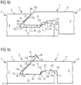
- a fourth embodiment show the FIGS. 4a to 4c , This is based on that embodiment of the group of figures 2. Like this, it has on the panel surface on the side of the locking groove a chamfer 18a, so that in the assembled state, a V-groove 19 is formed. Furthermore, together is a downwardly open recess 14 of the locking spring, which in the assembled state identical, as in Fig. 2c with a base surface 14a on a bearing surface 12f of the retaining strip 12 rests and is supported thereby.
- the embodiment of the group of figures 4 differs by a provided on the retaining bar 12 of the lower groove wall 11 second support surface 23 and a fittingly provided on the locking spring 9 second contact surface 24.
- two pairings of support surface / contact surface are effective. This doubling of holding / abutment surface in the assembled state improves the overall effect of the lock.
- the second support surface 23 sets at the upper end of the free surface 12d and ends at the free end of the strip 12a at the level of the support surface 12f of the retaining strip.
- the second contact surface 24 of the locking spring is arranged proximally relative to the first contact surface 15 and, in the assembled state, fits together with the second retaining surface 23 of the retaining strip.
- the design with doubled holding surfaces (12b / 23) and bearing surfaces (15/24) also has an advantage when the substrate U is uneven, that is, when it has a ripple.
- ripples is meant moderate slope / gradient of the subsurface, in the order of max. ⁇ 3 °. If two interlocked panels are laid on such a wavy ground and locked, then no more flat floor surface is formed. An angle of> 180 ° then arises between the panel surface of one panel and the panel surface of the other panel if the retaining profiles are located at a raised position of the ground. If they are at a low point of the ground, then an angle of ⁇ 180 ° is established between the two panel surfaces.
- each one of the pairs of support surface / contact surface remains in contact when the panel surfaces of the locked panels are in a position ⁇ 180 ° or> 180 ° to each other.
- a pair of holding surface / contact surface remains in good contact with each other, while the contact of the other pair of support surface / contact surface is lost, but the measure of loss of contact between holding surface / contact surface is only one tenth of a millimeter or even fractions of a tenth.
- a fifth exemplary embodiment is again based on the exemplary embodiment of the group of figures 2.
- an edge break 18 is provided on the upper groove wall 10.
- the edge refraction is in the form of a chamfer 18a .
- the retaining strip 12 protrudes into the recess 14 and supports its base 14a.
- the peculiarity of the fifth embodiment is the design of the spring top 16, which has a concave curvature 25, while the inner side 10a of the upper groove wall 10 matching a convex curvature 26 has.
- the two curvatures 25/26 abut each other.
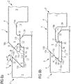
- a horizontal clearance P 'can be seen between the retaining surface 12b of the retaining strip and the contact surface 15 of the locking spring.
- the game P 'can of course be reduced to zero, creating a game P between the bends 25 and 26, as well as the game P in Fig. 2c ,
- Fig. 5a He starts as well as in Fig. 2a so that the spring underside 9 a store on the retaining strip 12 and then the locking spring 9 to push further in the direction of the locking groove 8.
- Fig. 5b the locking spring 9 abuts against the inside 10a of the upper groove wall. In the present example, this requires a lifting / angling of that panel with the locking spring by a small angle ⁇ .
- the design could also be changed and, for example, a larger clearance P could be provided, in order to be able to insert the locking spring 9 with less angulation or without any angling into the locking groove 8.
- a sixth embodiment is also based on the group of figures 2. Like this, it has on the panel surface 4 on that side of the locking groove 8 a chamfer 18a, so that in the assembled state, a V-groove 19 is formed. Furthermore, a downwardly open recess 14 of the locking spring 9 is provided in common, which in the assembled state identical, as in Fig. 2c , rests on the retaining strip 12 and the base 14a is supported thereby. New in the present embodiment, two recesses 27 in the spring base 9a and two recesses 28 in the support surface 11b of the lower groove wall 11. Each two recesses face each other and form together hollow chambers Y, in which, for example, dust or abrasion particles can collect. Alternatively, it is possible to arrange on the spring underside 9a or the support surface 11b fewer or more such recesses or recesses on only one side to be arranged on the support surface 11b or the lower spring side 9a.
- the group of figures 7 shows an embodiment, which in turn is based on the embodiment of the group of figures 2, because here on the panel surface 4 on that side of the locking groove 8 is a chamfer 18a, so that in the assembled state, a V-groove 19 is formed and because together with Figs. 2 a downwardly open recess 14 of the locking spring 9 is provided, which in the assembled state identical, as in Fig. 2c , rests on the support bar 12 and is supported by it.
- the retaining strip 12 of the lower groove wall 11 has a new design. It is namely at its, the recess 11a facing away from the outside with an edge refraction. This edge breakage is designed to serve as an inclined abutment surface 29 for the locking spring 9, as in FIG Fig. 7a indicated where the spring tip touches the contact surface and is moved upwards along this. In order for this to be possible, its distal end 29a reaches down to a level deep enough for the locking spring 9 of a new panel to abut against the start-up surface when the new panel rests on the ground U.
- FIGS. 8a to 8d An eighth embodiment is in the FIGS. 8a to 8d shown. It is based on that of the group of figures 1, to which it is changed in two aspects.
- the first aspect is the changed relation between the retaining strip 12 provided on the lower groove wall 11 and the downwardly open recess 14 of the locking spring 9.
- the design is such that in the assembled state the recess rests on the bearing surface 12f, as in FIG Fig. 8c / 8d shown.
- the other aspect is the particular design of the support surface 12b.
- the holding surface is executed undercut. It has a notch 30. The notch is arranged so that the support surface 11b of the lower groove wall is extended and merges into the notch.
- the contact surface 15 of the locking spring is further developed into a projection 31 which faces the panel core 3 'and practically forms an extension of the spring underside 9a.
- the projection 31 is designed so that it fits in the assembled state in the notch 30 and the position according to Fig. 8d counteracts a height offset.
- a rear positive locking is provided almost behind the spring underside 9a.
- Relative to the panel with locking groove is the rear positive locking on that side facing the panel core side of the retaining bar 12.
- Fig. 8b an intermediate position is shown during the joining movement.
- the underside of the spring is moved down along the free surface 12d, or the mentioned projection 31 slides down the free surface.
- Fig. 8c the position is shown with play P ', in which the spring top 16 bears against the inside 10a of the upper groove wall.
- Fig. 9 shows a plan view of a surface of laid panels, in which case use rectangular-format panels find that have at both edge pairs retaining profiles according to the group of figures 7.
- a first panel row of locked panels D1 and a second panel row D2 begun can be seen.
- the new panel has a first pair of edges with a locking spring 32a and opposite a locking groove 32c and a second pair of edges with a locking spring 32b opposite a locking groove 32d.
- a new panel 32 is to be connected. It must be locked for this purpose with panels 33 and 34 of the first panel row D1 and with the panel 35 of the second panel row D2.
- the new panel 32 is deposited on the underground U.
- the new panel is moved in the direction of the arrow V (diagonal). It approaches the locking grooves of the panels 33/34 of the first row of panels. At the same time, it approaches the locking groove of the panel 35.
- its locking springs 32a and 32b abut against abutment surfaces 35b and 33b / 34b respectively provided on the outside of the retaining strips of the adjacent panels 33, 34 and 35.
- the adhesive may be applied to the substrate and / or applied to the lower panel surface. It must have sufficient pot life to complete all laying steps before it hardens. After hardening / setting it causes a cohesive connection with the substrate U.
- the locking of the two involved locking springs 32a, 32b of the new panel 32 is generated almost simultaneously.
- locking of the locking spring of the new panel may begin with the locking groove of the already laid panel in that panel corner of the new panel, indicated by the arrow V, and starting in this panel corner, the generation of the latch zipper-like progressively takes place at both panel edges. It may be that a panel edge of the new panel is locked faster than the other; This is for example when the panel edges are of different lengths.
- Fig. 9 in that one locking spring is laid on the retaining strips of the panels of the first row of panels and the other locking spring is laid on the retaining strip of the panel already present in the second row of panels. Then slide diagonally, as indicated by the direction of arrow V, so that the new panel at both locking panel edges comes with the locking grooves of the adjacent panels in positive engagement.
- Fig. 10 shows a panel that follows the principle of Figure Group 8, ie it has a rear positive locking. This is realized by a notch 30 on the retaining strip of the locking groove and a suitably shaped projection 31 on the locking spring 9, which fits into the notch.
- the projection 31 is moved into the notch to the maximum depth so that the rear positive lock then achieves its best locking effect perpendicular to the panel surface.
- the projection 31 can pass freely through the proximal end of the free surface 12d and the spring underside 9a can reach the bearing surface 11b of the lower groove wall.
- a required during the joining process elastic deformation of the holding profiles is not provided in the present embodiment.
- the notch has a cross-section that is made using a milling tool.
- a dash-dotted line points in Fig. 10 the milling tool R and its drive spindle Z, around which rotates the milling tool.
- the locking groove is executed at its groove bottom with a larger radius.
- the distal end 16 a of the straight piece of the spring top 16 is at a slightly higher level than the support surface 12 f of the retaining strip 12, respectively, the strip end 12 a. It has the advantage that in the region of the enlarged radius, which forms the groove bottom of the locking groove, the risk of a crack can be reduced somewhat.
- An increased radius at the groove bottom is not only advantageous for the present embodiment, but also for all previous embodiments, a convenient option.
- the side of the notch closer to the panel surface has positive contact with an upper side of the projection. It can be provided between the free end of the projection and the bottom of the notch some air and thus formed a space.
- the space is used for the safe production of the positive connection and in addition, any dirt particles can be taken there.
- Fig. 11 shows an application of the panel according to the invention for the production of a covering surface in herringbone laying pattern.
- two different types of panel are needed, one type A and one type B.
- Both panel types A and B have an edge pair that is identically designed, ie the type A locking groove is located on the same panel edge as the type B and panel Similarly, the locking spring of type A on the same panel edge is arranged as in the panel type B.
- the other pair of edges is reversed to the type B designed for type A, ie that panel edge, which is provided in type A with the locking spring has type B the locking groove and vice versa.
- both types have a pair of long panel edges as well as a pair of short panel edges.
- the long panel edges are identical for type A designed as the type B.
- the short panel edges are different.
- the locking groove is provided in type B. Where type A has the locking groove is again arranged in type B, the locking spring.
- the retaining profiles of the long edges are first milled. Subsequently, the panels are transported within the production plant to mill the short edges, with half of the panels of a batch must be rotated by 180 ° before the milling cycle to make the short edges on this part of the panels reversed.
- This laying pattern requires that long panel edges and short panel edges can be locked together. Different edge pairs e.g. long edge short edge must therefore be compatible with each other. In this way, a herringbone laying pattern can be produced.
- the panels can be positively locked on all sides, with a locking effect being achieved in the panel plane (horizontal), perpendicular to the locked edges, but also achieving a locking action in a direction perpendicular to the panel plane (vertical).
- this horizontal and vertical locking action is possible on both edge pairs.
- FIG. 11 schematically shows an area of locked panels, which are arranged in herringbone laying pattern.
- a type A panel and a type B panel are distinguished by different hatching. It is indicated in each case with (F), where in the respective panel type a spring and with (N) respectively indicated, where there is a groove.
Landscapes
- Engineering & Computer Science (AREA)
- Architecture (AREA)
- Civil Engineering (AREA)
- Structural Engineering (AREA)
- Floor Finish (AREA)
- Connection Of Plates (AREA)
- Finishing Walls (AREA)
Priority Applications (6)
| Application Number | Priority Date | Filing Date | Title |
|---|---|---|---|
| EP17203608.9A EP3489431B1 (fr) | 2017-11-24 | 2017-11-24 | Panneau |
| PCT/EP2018/082383 WO2019101928A1 (fr) | 2017-11-24 | 2018-11-23 | Panneau |
| CA3083710A CA3083710C (fr) | 2017-11-24 | 2018-11-23 | Panneau |
| US16/766,406 US11168482B2 (en) | 2017-11-24 | 2018-11-23 | Panel |
| CN201880087503.3A CN111655949B (en) | 2017-11-24 | 2018-11-23 | Panel |
| RU2020120700A RU2751154C1 (ru) | 2017-11-24 | 2018-11-23 | Панель |
Applications Claiming Priority (1)
| Application Number | Priority Date | Filing Date | Title |
|---|---|---|---|
| EP17203608.9A EP3489431B1 (fr) | 2017-11-24 | 2017-11-24 | Panneau |
Publications (2)
| Publication Number | Publication Date |
|---|---|
| EP3489431A1 true EP3489431A1 (fr) | 2019-05-29 |
| EP3489431B1 EP3489431B1 (fr) | 2022-04-13 |
Family
ID=60569601
Family Applications (1)
| Application Number | Title | Priority Date | Filing Date |
|---|---|---|---|
| EP17203608.9A Active EP3489431B1 (fr) | 2017-11-24 | 2017-11-24 | Panneau |
Country Status (5)
| Country | Link |
|---|---|
| US (1) | US11168482B2 (fr) |
| EP (1) | EP3489431B1 (fr) |
| CA (1) | CA3083710C (fr) |
| RU (1) | RU2751154C1 (fr) |
| WO (1) | WO2019101928A1 (fr) |
Cited By (3)
| Publication number | Priority date | Publication date | Assignee | Title |
|---|---|---|---|---|
| CN114466962A (zh) * | 2019-09-25 | 2022-05-10 | 瓦林格创新股份有限公司 | 包括柔性沟槽的一组镶板 |
| CN114929978A (zh) * | 2019-12-23 | 2022-08-19 | 洁福有限公司 | 用于生产自锁式地面覆盖层的面板 |
| CN115419080A (zh) * | 2022-09-05 | 2022-12-02 | 中交二航局第四工程有限公司 | 一种狭小基坑水上钢支撑安装平台及其施工方法 |
Families Citing this family (7)
| Publication number | Priority date | Publication date | Assignee | Title |
|---|---|---|---|---|
| NL2020972B1 (en) | 2018-05-23 | 2019-12-02 | Innovations4Flooring Holding N V | Multi-purpose tile system, tile covering, and tile |
| US11136766B2 (en) * | 2019-05-18 | 2021-10-05 | Jiangsu Langyue New Materials Technology Co., Ltd. | Easy-to-assemble panel |
| JP7523528B2 (ja) * | 2019-09-06 | 2024-07-26 | アイ4エフ・ライセンシング・エヌヴィ | 床パネルおよび床 |
| US11840846B2 (en) * | 2020-05-12 | 2023-12-12 | Valinge Innovation Ab | Mineral-based panel |
| WO2022066087A1 (fr) | 2020-09-23 | 2022-03-31 | Välinge Innovation AB | Panneau de construction comprenant une couche à base minérale |
| DE202021003901U1 (de) * | 2021-12-30 | 2022-02-09 | Surface Technologies Gmbh & Co. Kg | Set aus zwei Paneelen zur Verkleidung einer Oberfläche und einem Paneelverbindungselement, Paneelverbindungselement und Verwendung eines Paneelverbindungselements |
| WO2025080195A1 (fr) * | 2023-10-13 | 2025-04-17 | Välinge Innovation AB | Dispositif de verrouillage mécanique pour panneaux de construction |
Citations (6)
| Publication number | Priority date | Publication date | Assignee | Title |
|---|---|---|---|---|
| US20040035077A1 (en) * | 1995-03-07 | 2004-02-26 | Goran Martensson | Flooring panel or wall panel and use thereof |
| US20090133353A1 (en) * | 2007-11-07 | 2009-05-28 | Valinge Innovation Ab | Mechanical Locking of Floor Panels with Vertical Snap Folding |
| DE202014008510U1 (de) * | 2014-10-28 | 2014-12-09 | Bfs Werkzeugsysteme Gmbh | Verbindungsanordnung zwischen stirnseitig aneinander angrenzenden flächigen, insbesondere plattenförmigen, Bauteilen, flächiges Bauteil sowie Bodenbelag |
| WO2015135533A1 (fr) * | 2014-03-10 | 2015-09-17 | Guido Schulte | Revêtement composé de panneaux pouvant être reliés les uns aux autres mécaniquement |
| DE102014114250A1 (de) | 2014-09-30 | 2016-03-31 | Akzenta Paneele + Profile Gmbh | Paneel |
| DE202016105668U1 (de) * | 2016-10-11 | 2016-11-10 | Franz Eschlbeck | Paneel und Paneelverbindung |
Family Cites Families (15)
| Publication number | Priority date | Publication date | Assignee | Title |
|---|---|---|---|---|
| US4426820A (en) * | 1979-04-24 | 1984-01-24 | Heinz Terbrack | Panel for a composite surface and a method of assembling same |
| SE9500810D0 (sv) | 1995-03-07 | 1995-03-07 | Perstorp Flooring Ab | Golvplatta |
| US7617651B2 (en) * | 2002-11-12 | 2009-11-17 | Kronotec Ag | Floor panel |
| EP1420125B1 (fr) * | 2002-11-15 | 2008-05-14 | Flooring Technologies Ltd. | Ensemble consistant en deux panneaux de construction interconnectables et un insert pour verrouiller ces panneaux |
| US8082717B2 (en) * | 2005-06-06 | 2011-12-27 | Dirk Dammers | Panel, in particular floor panel |
| DE102006006124A1 (de) * | 2006-02-10 | 2007-08-23 | Flooring Technologies Ltd. | Einrichtung zum Verriegeln zweier Bauplatten |
| US8499521B2 (en) | 2007-11-07 | 2013-08-06 | Valinge Innovation Ab | Mechanical locking of floor panels with vertical snap folding and an installation method to connect such panels |
| KR100958396B1 (ko) * | 2009-03-31 | 2010-05-18 | 오광석 | 바닥재 |
| DE102009019492A1 (de) * | 2009-05-04 | 2010-11-11 | Akzenta Paneele + Profile Gmbh | Verriegelungssystem für Paneele |
| EP4092213B1 (fr) * | 2010-01-11 | 2023-12-13 | Välinge Innovation AB | Revêtement de sol avec conception d'interverrouillage |
| EP2423410B1 (fr) | 2010-08-27 | 2013-02-13 | Barlinek S.A. | Panneau de construction doté de moyens de verrouillage améliorés pour la liaison amovible de panneaux de construction similaires |
| DE102010063976B4 (de) * | 2010-12-22 | 2013-01-17 | Akzenta Paneele + Profile Gmbh | Paneel |
| DE202011110452U1 (de) * | 2011-01-28 | 2014-02-11 | Akzenta Paneele + Profile Gmbh | Paneel |
| CN106164393B (zh) * | 2014-02-26 | 2018-11-23 | 创新四号地板控股有限公司 | 可与类似的镶板互连来形成覆盖装置的镶板 |
| DE102014106492A1 (de) * | 2014-05-08 | 2015-11-12 | Akzenta Paneele + Profile Gmbh | Paneel |
-
2017
- 2017-11-24 EP EP17203608.9A patent/EP3489431B1/fr active Active
-
2018
- 2018-11-23 WO PCT/EP2018/082383 patent/WO2019101928A1/fr not_active Ceased
- 2018-11-23 RU RU2020120700A patent/RU2751154C1/ru active
- 2018-11-23 US US16/766,406 patent/US11168482B2/en active Active
- 2018-11-23 CA CA3083710A patent/CA3083710C/fr active Active
Patent Citations (6)
| Publication number | Priority date | Publication date | Assignee | Title |
|---|---|---|---|---|
| US20040035077A1 (en) * | 1995-03-07 | 2004-02-26 | Goran Martensson | Flooring panel or wall panel and use thereof |
| US20090133353A1 (en) * | 2007-11-07 | 2009-05-28 | Valinge Innovation Ab | Mechanical Locking of Floor Panels with Vertical Snap Folding |
| WO2015135533A1 (fr) * | 2014-03-10 | 2015-09-17 | Guido Schulte | Revêtement composé de panneaux pouvant être reliés les uns aux autres mécaniquement |
| DE102014114250A1 (de) | 2014-09-30 | 2016-03-31 | Akzenta Paneele + Profile Gmbh | Paneel |
| DE202014008510U1 (de) * | 2014-10-28 | 2014-12-09 | Bfs Werkzeugsysteme Gmbh | Verbindungsanordnung zwischen stirnseitig aneinander angrenzenden flächigen, insbesondere plattenförmigen, Bauteilen, flächiges Bauteil sowie Bodenbelag |
| DE202016105668U1 (de) * | 2016-10-11 | 2016-11-10 | Franz Eschlbeck | Paneel und Paneelverbindung |
Cited By (4)
| Publication number | Priority date | Publication date | Assignee | Title |
|---|---|---|---|---|
| CN114466962A (zh) * | 2019-09-25 | 2022-05-10 | 瓦林格创新股份有限公司 | 包括柔性沟槽的一组镶板 |
| CN114929978A (zh) * | 2019-12-23 | 2022-08-19 | 洁福有限公司 | 用于生产自锁式地面覆盖层的面板 |
| CN114929978B (zh) * | 2019-12-23 | 2024-06-04 | 洁福有限公司 | 用于生产自锁式地面覆盖层的面板 |
| CN115419080A (zh) * | 2022-09-05 | 2022-12-02 | 中交二航局第四工程有限公司 | 一种狭小基坑水上钢支撑安装平台及其施工方法 |
Also Published As
| Publication number | Publication date |
|---|---|
| CA3083710C (fr) | 2022-04-26 |
| US11168482B2 (en) | 2021-11-09 |
| US20200378136A1 (en) | 2020-12-03 |
| CA3083710A1 (fr) | 2019-05-31 |
| WO2019101928A1 (fr) | 2019-05-31 |
| CN111655949A (zh) | 2020-09-11 |
| EP3489431B1 (fr) | 2022-04-13 |
| RU2751154C1 (ru) | 2021-07-08 |
Similar Documents
| Publication | Publication Date | Title |
|---|---|---|
| EP3489431B1 (fr) | Panneau | |
| EP2213812B1 (fr) | Panneau, en particulier panneau de sol | |
| EP2459818B1 (fr) | Revêtement composé de panneaux mécaniquement reliables entre eux | |
| EP2057327B1 (fr) | Panneau, notamment panneau de sol | |
| EP3298212B1 (fr) | Garniture de panneaux rectangulaires ou carrés joints les uns aux autres | |
| EP2226447B1 (fr) | Panneau, en particulier panneau de sol | |
| EP1224365B1 (fr) | Panneaux pour revêtement de sol | |
| EP1730366B1 (fr) | Panneau pour revêtement | |
| WO2010006684A2 (fr) | Procédé d'application de panneaux de sol | |
| DE10214972A1 (de) | Paneel sowie Verriegelungssystem für Paneele | |
| EP1891283A1 (fr) | Panneau pour plancher possedant une partie centrale en materiau derive du bois, une couche de decoration et des profils de verrouillage | |
| DE102007015048A1 (de) | Paneel, insbesondere Bodenpaneel | |
| WO2003069095A1 (fr) | Panneau, en particulier panneau de revetement de sol | |
| WO2010100046A1 (fr) | Panneau destiné à former un revêtement et procédé de fabrication d'un tel revêtement | |
| DE102011110071A1 (de) | Verfahren zum Verlegen und Verbinden von Gebäudeplatten sowie Verriegelungsvorrichtung für Gebäudeplatten | |
| EP1203854B1 (fr) | Panneau avec une mortaise et un double tenon | |
| DE202009011997U1 (de) | Paneel zur Bildung eines Belags | |
| EP1208274B1 (fr) | Systeme de pierres de construction | |
| EP1416103A1 (fr) | Revêtement de sol comprenant des panneaux assemblables | |
| EP3907346A1 (fr) | Panneau à profilés multiples | |
| DE29520712U1 (de) | Bausatz mit Mauersteinen | |
| DE29924536U1 (de) | Rechtwinklige Holz- oder Laminatbodenplatte | |
| DE20122682U1 (de) | Verriegelungssystem für Bodenplatten |
Legal Events
| Date | Code | Title | Description |
|---|---|---|---|
| PUAI | Public reference made under article 153(3) epc to a published international application that has entered the european phase |
Free format text: ORIGINAL CODE: 0009012 |
|
| STAA | Information on the status of an ep patent application or granted ep patent |
Free format text: STATUS: THE APPLICATION HAS BEEN PUBLISHED |
|
| AK | Designated contracting states |
Kind code of ref document: A1 Designated state(s): AL AT BE BG CH CY CZ DE DK EE ES FI FR GB GR HR HU IE IS IT LI LT LU LV MC MK MT NL NO PL PT RO RS SE SI SK SM TR |
|
| AX | Request for extension of the european patent |
Extension state: BA ME |
|
| STAA | Information on the status of an ep patent application or granted ep patent |
Free format text: STATUS: REQUEST FOR EXAMINATION WAS MADE |
|
| 17P | Request for examination filed |
Effective date: 20191129 |
|
| RBV | Designated contracting states (corrected) |
Designated state(s): AL AT BE BG CH CY CZ DE DK EE ES FI FR GB GR HR HU IE IS IT LI LT LU LV MC MK MT NL NO PL PT RO RS SE SI SK SM TR |
|
| STAA | Information on the status of an ep patent application or granted ep patent |
Free format text: STATUS: EXAMINATION IS IN PROGRESS |
|
| 17Q | First examination report despatched |
Effective date: 20200519 |
|
| GRAP | Despatch of communication of intention to grant a patent |
Free format text: ORIGINAL CODE: EPIDOSNIGR1 |
|
| STAA | Information on the status of an ep patent application or granted ep patent |
Free format text: STATUS: GRANT OF PATENT IS INTENDED |
|
| INTG | Intention to grant announced |
Effective date: 20210408 |
|
| GRAJ | Information related to disapproval of communication of intention to grant by the applicant or resumption of examination proceedings by the epo deleted |
Free format text: ORIGINAL CODE: EPIDOSDIGR1 |
|
| STAA | Information on the status of an ep patent application or granted ep patent |
Free format text: STATUS: EXAMINATION IS IN PROGRESS |
|
| INTC | Intention to grant announced (deleted) | ||
| GRAS | Grant fee paid |
Free format text: ORIGINAL CODE: EPIDOSNIGR3 |
|
| STAA | Information on the status of an ep patent application or granted ep patent |
Free format text: STATUS: GRANT OF PATENT IS INTENDED |
|
| GRAP | Despatch of communication of intention to grant a patent |
Free format text: ORIGINAL CODE: EPIDOSNIGR1 |
|
| GRAJ | Information related to disapproval of communication of intention to grant by the applicant or resumption of examination proceedings by the epo deleted |
Free format text: ORIGINAL CODE: EPIDOSDIGR1 |
|
| GRAS | Grant fee paid |
Free format text: ORIGINAL CODE: EPIDOSNIGR3 |
|
| GRAP | Despatch of communication of intention to grant a patent |
Free format text: ORIGINAL CODE: EPIDOSNIGR1 |
|
| GRAJ | Information related to disapproval of communication of intention to grant by the applicant or resumption of examination proceedings by the epo deleted |
Free format text: ORIGINAL CODE: EPIDOSDIGR1 |
|
| GRAL | Information related to payment of fee for publishing/printing deleted |
Free format text: ORIGINAL CODE: EPIDOSDIGR3 |
|
| STAA | Information on the status of an ep patent application or granted ep patent |
Free format text: STATUS: EXAMINATION IS IN PROGRESS |
|
| INTG | Intention to grant announced |
Effective date: 20211013 |
|
| INTG | Intention to grant announced |
Effective date: 20211027 |
|
| GRAP | Despatch of communication of intention to grant a patent |
Free format text: ORIGINAL CODE: EPIDOSNIGR1 |
|
| STAA | Information on the status of an ep patent application or granted ep patent |
Free format text: STATUS: GRANT OF PATENT IS INTENDED |
|
| INTC | Intention to grant announced (deleted) | ||
| INTG | Intention to grant announced |
Effective date: 20211203 |
|
| GRAA | (expected) grant |
Free format text: ORIGINAL CODE: 0009210 |
|
| STAA | Information on the status of an ep patent application or granted ep patent |
Free format text: STATUS: THE PATENT HAS BEEN GRANTED |
|
| AK | Designated contracting states |
Kind code of ref document: B1 Designated state(s): AL AT BE BG CH CY CZ DE DK EE ES FI FR GB GR HR HU IE IS IT LI LT LU LV MC MK MT NL NO PL PT RO RS SE SI SK SM TR |
|
| REG | Reference to a national code |
Ref country code: GB Ref legal event code: FG4D Free format text: NOT ENGLISH |
|
| REG | Reference to a national code |
Ref country code: CH Ref legal event code: EP |
|
| REG | Reference to a national code |
Ref country code: DE Ref legal event code: R096 Ref document number: 502017012952 Country of ref document: DE |
|
| REG | Reference to a national code |
Ref country code: IE Ref legal event code: FG4D Free format text: LANGUAGE OF EP DOCUMENT: GERMAN |
|
| REG | Reference to a national code |
Ref country code: AT Ref legal event code: REF Ref document number: 1483524 Country of ref document: AT Kind code of ref document: T Effective date: 20220515 |
|
| REG | Reference to a national code |
Ref country code: LT Ref legal event code: MG9D |
|
| REG | Reference to a national code |
Ref country code: NL Ref legal event code: MP Effective date: 20220413 |
|
| PG25 | Lapsed in a contracting state [announced via postgrant information from national office to epo] |
Ref country code: NL Free format text: LAPSE BECAUSE OF FAILURE TO SUBMIT A TRANSLATION OF THE DESCRIPTION OR TO PAY THE FEE WITHIN THE PRESCRIBED TIME-LIMIT Effective date: 20220413 |
|
| PG25 | Lapsed in a contracting state [announced via postgrant information from national office to epo] |
Ref country code: SE Free format text: LAPSE BECAUSE OF FAILURE TO SUBMIT A TRANSLATION OF THE DESCRIPTION OR TO PAY THE FEE WITHIN THE PRESCRIBED TIME-LIMIT Effective date: 20220413 Ref country code: PT Free format text: LAPSE BECAUSE OF FAILURE TO SUBMIT A TRANSLATION OF THE DESCRIPTION OR TO PAY THE FEE WITHIN THE PRESCRIBED TIME-LIMIT Effective date: 20220816 Ref country code: NO Free format text: LAPSE BECAUSE OF FAILURE TO SUBMIT A TRANSLATION OF THE DESCRIPTION OR TO PAY THE FEE WITHIN THE PRESCRIBED TIME-LIMIT Effective date: 20220713 Ref country code: LT Free format text: LAPSE BECAUSE OF FAILURE TO SUBMIT A TRANSLATION OF THE DESCRIPTION OR TO PAY THE FEE WITHIN THE PRESCRIBED TIME-LIMIT Effective date: 20220413 Ref country code: HR Free format text: LAPSE BECAUSE OF FAILURE TO SUBMIT A TRANSLATION OF THE DESCRIPTION OR TO PAY THE FEE WITHIN THE PRESCRIBED TIME-LIMIT Effective date: 20220413 Ref country code: FI Free format text: LAPSE BECAUSE OF FAILURE TO SUBMIT A TRANSLATION OF THE DESCRIPTION OR TO PAY THE FEE WITHIN THE PRESCRIBED TIME-LIMIT Effective date: 20220413 Ref country code: ES Free format text: LAPSE BECAUSE OF FAILURE TO SUBMIT A TRANSLATION OF THE DESCRIPTION OR TO PAY THE FEE WITHIN THE PRESCRIBED TIME-LIMIT Effective date: 20220413 Ref country code: BG Free format text: LAPSE BECAUSE OF FAILURE TO SUBMIT A TRANSLATION OF THE DESCRIPTION OR TO PAY THE FEE WITHIN THE PRESCRIBED TIME-LIMIT Effective date: 20220713 |
|
| PG25 | Lapsed in a contracting state [announced via postgrant information from national office to epo] |
Ref country code: RS Free format text: LAPSE BECAUSE OF FAILURE TO SUBMIT A TRANSLATION OF THE DESCRIPTION OR TO PAY THE FEE WITHIN THE PRESCRIBED TIME-LIMIT Effective date: 20220413 Ref country code: PL Free format text: LAPSE BECAUSE OF FAILURE TO SUBMIT A TRANSLATION OF THE DESCRIPTION OR TO PAY THE FEE WITHIN THE PRESCRIBED TIME-LIMIT Effective date: 20220413 Ref country code: LV Free format text: LAPSE BECAUSE OF FAILURE TO SUBMIT A TRANSLATION OF THE DESCRIPTION OR TO PAY THE FEE WITHIN THE PRESCRIBED TIME-LIMIT Effective date: 20220413 Ref country code: IS Free format text: LAPSE BECAUSE OF FAILURE TO SUBMIT A TRANSLATION OF THE DESCRIPTION OR TO PAY THE FEE WITHIN THE PRESCRIBED TIME-LIMIT Effective date: 20220813 |
|
| REG | Reference to a national code |
Ref country code: DE Ref legal event code: R097 Ref document number: 502017012952 Country of ref document: DE |
|
| PG25 | Lapsed in a contracting state [announced via postgrant information from national office to epo] |
Ref country code: SM Free format text: LAPSE BECAUSE OF FAILURE TO SUBMIT A TRANSLATION OF THE DESCRIPTION OR TO PAY THE FEE WITHIN THE PRESCRIBED TIME-LIMIT Effective date: 20220413 Ref country code: SK Free format text: LAPSE BECAUSE OF FAILURE TO SUBMIT A TRANSLATION OF THE DESCRIPTION OR TO PAY THE FEE WITHIN THE PRESCRIBED TIME-LIMIT Effective date: 20220413 Ref country code: RO Free format text: LAPSE BECAUSE OF FAILURE TO SUBMIT A TRANSLATION OF THE DESCRIPTION OR TO PAY THE FEE WITHIN THE PRESCRIBED TIME-LIMIT Effective date: 20220413 Ref country code: EE Free format text: LAPSE BECAUSE OF FAILURE TO SUBMIT A TRANSLATION OF THE DESCRIPTION OR TO PAY THE FEE WITHIN THE PRESCRIBED TIME-LIMIT Effective date: 20220413 Ref country code: DK Free format text: LAPSE BECAUSE OF FAILURE TO SUBMIT A TRANSLATION OF THE DESCRIPTION OR TO PAY THE FEE WITHIN THE PRESCRIBED TIME-LIMIT Effective date: 20220413 Ref country code: CZ Free format text: LAPSE BECAUSE OF FAILURE TO SUBMIT A TRANSLATION OF THE DESCRIPTION OR TO PAY THE FEE WITHIN THE PRESCRIBED TIME-LIMIT Effective date: 20220413 |
|
| PLBE | No opposition filed within time limit |
Free format text: ORIGINAL CODE: 0009261 |
|
| STAA | Information on the status of an ep patent application or granted ep patent |
Free format text: STATUS: NO OPPOSITION FILED WITHIN TIME LIMIT |
|
| 26N | No opposition filed |
Effective date: 20230116 |
|
| PG25 | Lapsed in a contracting state [announced via postgrant information from national office to epo] |
Ref country code: AL Free format text: LAPSE BECAUSE OF FAILURE TO SUBMIT A TRANSLATION OF THE DESCRIPTION OR TO PAY THE FEE WITHIN THE PRESCRIBED TIME-LIMIT Effective date: 20220413 |
|
| PG25 | Lapsed in a contracting state [announced via postgrant information from national office to epo] |
Ref country code: SI Free format text: LAPSE BECAUSE OF FAILURE TO SUBMIT A TRANSLATION OF THE DESCRIPTION OR TO PAY THE FEE WITHIN THE PRESCRIBED TIME-LIMIT Effective date: 20220413 |
|
| PG25 | Lapsed in a contracting state [announced via postgrant information from national office to epo] |
Ref country code: MC Free format text: LAPSE BECAUSE OF FAILURE TO SUBMIT A TRANSLATION OF THE DESCRIPTION OR TO PAY THE FEE WITHIN THE PRESCRIBED TIME-LIMIT Effective date: 20220413 |
|
| P01 | Opt-out of the competence of the unified patent court (upc) registered |
Effective date: 20230526 |
|
| GBPC | Gb: european patent ceased through non-payment of renewal fee |
Effective date: 20221124 |
|
| PG25 | Lapsed in a contracting state [announced via postgrant information from national office to epo] |
Ref country code: LU Free format text: LAPSE BECAUSE OF NON-PAYMENT OF DUE FEES Effective date: 20221124 |
|
| PG25 | Lapsed in a contracting state [announced via postgrant information from national office to epo] |
Ref country code: IE Free format text: LAPSE BECAUSE OF NON-PAYMENT OF DUE FEES Effective date: 20221124 Ref country code: GB Free format text: LAPSE BECAUSE OF NON-PAYMENT OF DUE FEES Effective date: 20221124 |
|
| PG25 | Lapsed in a contracting state [announced via postgrant information from national office to epo] |
Ref country code: IT Free format text: LAPSE BECAUSE OF FAILURE TO SUBMIT A TRANSLATION OF THE DESCRIPTION OR TO PAY THE FEE WITHIN THE PRESCRIBED TIME-LIMIT Effective date: 20220413 |
|
| PG25 | Lapsed in a contracting state [announced via postgrant information from national office to epo] |
Ref country code: HU Free format text: LAPSE BECAUSE OF FAILURE TO SUBMIT A TRANSLATION OF THE DESCRIPTION OR TO PAY THE FEE WITHIN THE PRESCRIBED TIME-LIMIT; INVALID AB INITIO Effective date: 20171124 |
|
| PG25 | Lapsed in a contracting state [announced via postgrant information from national office to epo] |
Ref country code: CY Free format text: LAPSE BECAUSE OF FAILURE TO SUBMIT A TRANSLATION OF THE DESCRIPTION OR TO PAY THE FEE WITHIN THE PRESCRIBED TIME-LIMIT Effective date: 20220413 |
|
| PG25 | Lapsed in a contracting state [announced via postgrant information from national office to epo] |
Ref country code: MK Free format text: LAPSE BECAUSE OF FAILURE TO SUBMIT A TRANSLATION OF THE DESCRIPTION OR TO PAY THE FEE WITHIN THE PRESCRIBED TIME-LIMIT Effective date: 20220413 |
|
| PG25 | Lapsed in a contracting state [announced via postgrant information from national office to epo] |
Ref country code: TR Free format text: LAPSE BECAUSE OF FAILURE TO SUBMIT A TRANSLATION OF THE DESCRIPTION OR TO PAY THE FEE WITHIN THE PRESCRIBED TIME-LIMIT Effective date: 20220413 |
|
| PG25 | Lapsed in a contracting state [announced via postgrant information from national office to epo] |
Ref country code: MT Free format text: LAPSE BECAUSE OF FAILURE TO SUBMIT A TRANSLATION OF THE DESCRIPTION OR TO PAY THE FEE WITHIN THE PRESCRIBED TIME-LIMIT Effective date: 20220413 |
|
| PG25 | Lapsed in a contracting state [announced via postgrant information from national office to epo] |
Ref country code: BG Free format text: LAPSE BECAUSE OF FAILURE TO SUBMIT A TRANSLATION OF THE DESCRIPTION OR TO PAY THE FEE WITHIN THE PRESCRIBED TIME-LIMIT Effective date: 20220413 |
|
| PG25 | Lapsed in a contracting state [announced via postgrant information from national office to epo] |
Ref country code: BG Free format text: LAPSE BECAUSE OF FAILURE TO SUBMIT A TRANSLATION OF THE DESCRIPTION OR TO PAY THE FEE WITHIN THE PRESCRIBED TIME-LIMIT Effective date: 20220413 |
|
| PG25 | Lapsed in a contracting state [announced via postgrant information from national office to epo] |
Ref country code: GR Free format text: LAPSE BECAUSE OF NON-PAYMENT OF DUE FEES Effective date: 20220413 |
|
| PG25 | Lapsed in a contracting state [announced via postgrant information from national office to epo] |
Ref country code: GR Free format text: LAPSE BECAUSE OF NON-PAYMENT OF DUE FEES Effective date: 20220413 |
|
| REG | Reference to a national code |
Ref country code: CH Ref legal event code: U11 Free format text: ST27 STATUS EVENT CODE: U-0-0-U10-U11 (AS PROVIDED BY THE NATIONAL OFFICE) Effective date: 20251201 |
|
| PGFP | Annual fee paid to national office [announced via postgrant information from national office to epo] |
Ref country code: AT Payment date: 20251117 Year of fee payment: 9 |
|
| PGFP | Annual fee paid to national office [announced via postgrant information from national office to epo] |
Ref country code: FR Payment date: 20251120 Year of fee payment: 9 |
|
| PGFP | Annual fee paid to national office [announced via postgrant information from national office to epo] |
Ref country code: BE Payment date: 20251118 Year of fee payment: 9 |
|
| PGFP | Annual fee paid to national office [announced via postgrant information from national office to epo] |
Ref country code: CH Payment date: 20251201 Year of fee payment: 9 |
|
| PGFP | Annual fee paid to national office [announced via postgrant information from national office to epo] |
Ref country code: DE Payment date: 20260128 Year of fee payment: 9 |