EP3489450A1 - Tor - Google Patents
Tor Download PDFInfo
- Publication number
- EP3489450A1 EP3489450A1 EP18198312.3A EP18198312A EP3489450A1 EP 3489450 A1 EP3489450 A1 EP 3489450A1 EP 18198312 A EP18198312 A EP 18198312A EP 3489450 A1 EP3489450 A1 EP 3489450A1
- Authority
- EP
- European Patent Office
- Prior art keywords
- spar
- holding plate
- transverse direction
- passage
- longitudinal guide
- Prior art date
- Legal status (The legal status is an assumption and is not a legal conclusion. Google has not performed a legal analysis and makes no representation as to the accuracy of the status listed.)
- Granted
Links
Images

Classifications
-
- E—FIXED CONSTRUCTIONS
- E06—DOORS, WINDOWS, SHUTTERS, OR ROLLER BLINDS IN GENERAL; LADDERS
- E06B—FIXED OR MOVABLE CLOSURES FOR OPENINGS IN BUILDINGS, VEHICLES, FENCES OR LIKE ENCLOSURES IN GENERAL, e.g. DOORS, WINDOWS, BLINDS, GATES
- E06B9/00—Screening or protective devices for wall or similar openings, with or without operating or securing mechanisms; Closures of similar construction
- E06B9/02—Shutters, movable grilles, or other safety closing devices, e.g. against burglary
- E06B9/08—Roll-type closures
- E06B9/11—Roller shutters
- E06B9/13—Roller shutters with closing members of one piece, e.g. of corrugated sheet metal
-
- E—FIXED CONSTRUCTIONS
- E06—DOORS, WINDOWS, SHUTTERS, OR ROLLER BLINDS IN GENERAL; LADDERS
- E06B—FIXED OR MOVABLE CLOSURES FOR OPENINGS IN BUILDINGS, VEHICLES, FENCES OR LIKE ENCLOSURES IN GENERAL, e.g. DOORS, WINDOWS, BLINDS, GATES
- E06B9/00—Screening or protective devices for wall or similar openings, with or without operating or securing mechanisms; Closures of similar construction
- E06B9/56—Operating, guiding or securing devices or arrangements for roll-type closures; Spring drums; Tape drums; Counterweighting arrangements therefor
- E06B9/58—Guiding devices
- E06B9/581—Means to prevent or induce disengagement of shutter from side rails
-
- E—FIXED CONSTRUCTIONS
- E06—DOORS, WINDOWS, SHUTTERS, OR ROLLER BLINDS IN GENERAL; LADDERS
- E06B—FIXED OR MOVABLE CLOSURES FOR OPENINGS IN BUILDINGS, VEHICLES, FENCES OR LIKE ENCLOSURES IN GENERAL, e.g. DOORS, WINDOWS, BLINDS, GATES
- E06B9/00—Screening or protective devices for wall or similar openings, with or without operating or securing mechanisms; Closures of similar construction
- E06B9/02—Shutters, movable grilles, or other safety closing devices, e.g. against burglary
- E06B9/08—Roll-type closures
- E06B9/11—Roller shutters
- E06B9/13—Roller shutters with closing members of one piece, e.g. of corrugated sheet metal
- E06B2009/135—Horizontal shutter reinforcements
Definitions
- the invention relates to a door with a guided in at least one longitudinal guide in a closing direction between an open position and a closed position door leaf.
- the door leaf extends in the closed position substantially in the closing direction in and perpendicular thereto transverse direction.
- the door leaf has a plurality of sections of a flexible material and at least one disposed between two adjacent in the closing direction and sections connected to these Holm.
- the spar extends in the transverse direction through an opening of the longitudinal guide, which has an opening width measured in a direction of passage perpendicular to the closing direction and to the transverse direction.
- Gates are used in particular for closing building openings and passages within walls. Generic gates have a flexible door leaf, which can be rolled up to save space.
- the flexibility of the door leaf hereby obtained by a plurality of sections of a flexible material.
- a flexible material may in particular be a plastic film or plastic tarpaulin.
- This is expediently reinforced by an embedded and / or laminated tissue.
- Such a flexible drapery has the advantage that, despite its low material thickness of a few millimeters, in particular less than 1 cm, it can form a vision-proof and hermetic seal and at the same time can be rolled up in a particularly space-saving manner.
- Another advantage is the low price of the sheet material.
- the sections of the flexible material may be formed of separate and / or contiguous pieces of material.
- the door leaf in the transverse direction is therefore provided at the generic gates at least one extending in the transverse direction spar.
- the stability of the door leaf is increased transversely to the intended winding, so that in normal operation, the door leaf can not leave the longitudinal guide.
- the invention has for its object to ensure the stability of a generic door leaf, even at high loads.
- a holding plate which is fastened in the transverse direction end to the spar and in the passage direction over the spar, preferably on both sides, constraintserstreckt.
- the opening of the longitudinal guide is bounded on both sides by two boundaries running in the passage direction. In the case of a load of the spar in the passage direction of this is first pressed against one of the boundaries. In a further load, the contact point between the boundary and the spar serves as a support point, so that a further load of the spar in the direction of passage leads to a bending moment. Due to the length shortening as a result of the deflection, the end region of the spar subsequently moves out of the opening of the longitudinal guide.
- the projecting retaining plate according to the invention now engages behind that edge of the opening with which the spar is in contact and thereby prevents complete removal of the spar. Traction forces can thus be absorbed by the positive-locking rear grip. At the same time, a holding plate can be produced and mounted with simple means.
- the spar on a receptacle in which a flexible portion of the door leaf is held in which a flexible portion of the door leaf is held.
- the holding plate holds this flexible portion in the transverse direction within the receptacle.
- the retaining plate thus has a dual function and does not wear only contributes to the stability of the door leaf under wind load, but also serves the cohesion of the individual components of the door leaf. Such a dual function is desirable in particular because of the reduced installation effort and because of the limited space within the spar.
- the receptacle has a cavity and an access opening with a reduced width compared to the cavity.
- a packing is arranged within the cavity.
- the flexible portion forms a loop which extends through the access opening of the cavity and surrounds the filling body therein.
- the filler body has an oversize relative to the access opening, so that the filler body - and thus the loop of the flexible section which wraps around it - can not leave the cavity through the access opening.
- the receptacle is uniform in the longitudinal direction of the spar (transverse direction). To connect the section with the spar, the loop and the filler must be inserted in the longitudinal direction of the spar in the recording. By subsequently mounted mounting plate, the loop with the filler can not leave the recording in this direction, so that it is securely fixed.
- the end of the piece of material forming the loop can be connected, in particular welded, to another part of this piece of material.
- the two adjacent, connected to a spar sections are formed from a contiguous piece of material.
- the piece of material can first be passed as a loop through a first cavity, then placed around the spar around, and then passed through a second cavity also as a loop.
- the spar is designed to save weight as a hollow profile, in particular as extruded hollow profile.
- a particularly preferred material for this is aluminum, which can be particularly easily processed in this manufacturing process.
- the extrusion process almost any cross-sectional shapes of hollow profiles can be extruded, which can be tailored to a suitable length (depending on the intended extent of the gate in the transverse direction) can be cut to length. It can thus extrude endless geometries, such as a cavity with through hole or corresponding screw holes for the attachment of the holding plate.
- the insert is expediently formed from a different material than the hollow profile.
- an insert is arranged within the hollow profile.
- the insert serves the additional stabilization of the spar.
- a steel rod is provided.
- steel As a material, it is also advantageous that it has better elastic bending properties than, for example, aluminum (as the material for the hollow profile).
- a (consuming, for example, steel) machining to achieve a special shape is not necessary.
- a simple steel rod with a rectangular cross section can be used.
- the retaining plate closes the cavity of the hollow profile in which the insert is located, so that this can not leave the hollow profile.
- the insert can also serve as additional weighting, especially in the case of vertically closing gates. As a result, the door leaf is held in tension in the closing direction.
- the width of the holding plate in the passage direction is greater than the opening width of the longitudinal guide.
- the supernatant of the holding plate with respect to the spar in the passage direction in particular on both sides, less than the difference between the opening width and the thickness of the spar in the passage direction. This ensures that only one of the two supernatants of the retaining plate is in positive engagement with an associated boundary of the opening at a load of the spar in the direction of passage. If the spar is pressed against a boundary by application of force and an associated projection of the retaining plate has hooked behind this associated boundary, the projection on the opposite side can not come into contact with the edge of the longitudinal guide. In a further force, the force acting direction facing away from the supernatant end of the holding plate can swing out of the longitudinal guide. The force acting on the retaining plate concentrates on the opposite side. Thus, the boundary of the longitudinal guide is loaded only on one side.
- the holding plate kinks and / or jumps out of the longitudinal guide, so that damage to the longitudinal guide is avoided.
- the holding plate is formed as a piece of sheet metal, in particular of sheet steel with a thickness of between 3 mm and 10 mm, preferably between 4 mm and 5 mm. Sheet metal pieces can be easily manufactured with little effort and low costs.
- the holding plate is - as the name implies - plate-shaped, with their width in the passage direction and their height in the closing direction by at least an order of magnitude greater than their thickness (in the transverse direction) are formed.
- the retaining plate is bolted to the spar.
- a screw connection By a screw connection, a particularly simple attachment to the spar can be achieved.
- This preferably has screw receptacles into which the screws can be screwed.
- the screw receptacles can be formed endless, in particular in an extruded profile.
- the screw receptacles on a prefabricated internal thread.
- the screws can also be designed self-tapping and screw into the material of the spar.
- the holding plate viewed in the transverse direction has a rounded profile.
- the outer contour of the retaining plate follows in particular a convex curve with a minimum radius of curvature of at least 5 mm.
- Boundaries of the opening of the longitudinal guide can in particular project flexible sealing elements in the direction of the opening. These can easily be deformed under the action of force and do not count towards the edge of the opening and also do not form an abutment for the retaining plate in the event of loading.
- the sealing elements may be formed in particular as bristle strips or as sealing lips made of an elastomeric material. The sealing elements provide - at least in normal operation - a sealing closure between the longitudinal guide and at least the spar of the door leaf ago.
- the door is designed as a vertical roller door. That is, the closing direction is identical to a vertical direction.
- the longitudinal guides are also referred to as side guides.
- a winding roller is provided for rolling up the door leaf.
- the roller door is designed in particular as a high-speed roll-up door with a travel speed of at least 1.5 m per second, preferably at least 2 m per second.
- the door is guided in the transverse direction on both sides on longitudinal guides, in particular side guides, and has on the spar at both ends, preferably identical holding plates.
- the longitudinal guide can be designed in particular as a multipart guide rail or as a C-shaped box section. Conveniently, the longitudinal guide is attached to a wall with an opening to be closed by the gate.
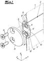
- FIG. 1 is a detailed view of the door leaf of a gate according to the invention in an exploded view.
- the door leaf comprises a first flexible section 1 and a second flexible section 1 ', which are both connected to a spar 2.
- the flexible sections 1, 1 ' are formed from a flexible plastic sheet.
- the flexible portions 1, 1 ' In the perpendicular thereto passage direction z of the gate, the flexible portions 1, 1 'only a small thickness of a few millimeters.
- a holding plate 3 is fastened to the end of the end 2, which on both sides protrudes beyond the spar 2 in the passage direction z.
- the holding plate 3 is by means of two screws 4 fastened to the Holm 2 designed as a hollow profile.
- the screws 4 engage in associated receptacles 5, which are formed as part of the extruded hollow profile of the spar 2.
- the two flexible sections 1, 1 'each have a loop 6, 6' which extends through an access opening 7, 7 'of the spar into a respective cavity 8, 8'.
- the flexible sections 1, 1 'in the pulling direction relative to the spar 2 are determined.
- the cavities 8, 8 'in the transverse direction x end closed, so that slipping out of the flexible sections 1, 1' in this direction is impossible.
- the hollow profile of the spar 2 includes an insert 10 in the form of a rectangular cross-section steel rod.
- the cross section of the steel rod is oriented so that it has a larger dimension in the passage direction z than in the closing direction y. This prevents bending of the beam 2 in the x-z plane.
- the spar 2 has a larger dimension in the closing direction y than in the passage direction z. The intrinsic stiffnesses of spar 2 and insert 10 thus complement each other.
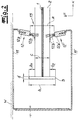
- the Fig. 2 shows a horizontal section in a conventional installation situation of a door according to the invention.
- the closing direction y coincides with the vertical direction together so that the illustrated horizontal section is in the xz plane.
- the door leaf is cut by a flexible section 1 so that it is visible in cross-section as well as the spar 2 and the holding plate 3 mounted end-to-end in the transverse direction x.
- the longitudinal guide or side guide of the door is designed as a C-shaped box profile, which is in two parts composed of two partial profiles 11, 11 '.
- the first part 11 is fixed to a wall W, which forms by the gate according to the invention to be closed door opening.
- sealing strips 12, 12' plugged. These comprise a holder 12a, 12a 'connected to the metal profile 11, 11' and bristle strips 12b, 12b 'protruding therefrom in the direction of the door leaf.
- the bristle strips extend in the unloaded, illustrated state at least to the spar 2 and stand in contact with this. Between the flexible curtain 1 and the bristle strips 12b, 12b 'remains at most a small distance. The distance between the unloaded bristles of the bristle strips 12b, 12b 'is less than half of the extension of the spar 2 in the passage direction z.
- the area between the two non-flexible retaining strips 12a, 12a ' forms the opening 13 of the longitudinal guide.
- the smallest distance in the passage direction z between the two retaining strips 12a, 12a ' is also referred to as opening width a.
- the door leaf extends including the flexible section 1, the spar 2 and the holding plate 3 in the box section of the longitudinal guide 11, 11 ', 12, 12' in.
- the holding plate 3 is arranged completely within the longitudinal guide.
- the holding plate has a width b in the passage direction z and stands relative to the spar 2 in a first direction facing the wall W by a first amount b 1 and in a second opposite direction by an amount b 2 in the passage direction z over.
- the width b of the holding plate 3 is greater than the opening width a of the longitudinal guide.
- the protrusion b 1 or b 2 of the holding plate 3 with respect to the spar 2 in the passage direction z is less than the difference between the opening width a and the thickness c of the spar 2 in the passage direction z.
- FIGS. 3a and 3b illustrated load fold clearly By a directed away from the wall 12 ( Fig. 3A ) or directed towards the wall ( Fig. 3B ) Force the spar 2 is pressed against the formed by the retaining strip 12a 'and 12a boundary of the longitudinal guide. In a further load, the spar 2 bends in the xz-plane, so that the end of the spar 2, on which the holding plate 3 is fixed in the transverse direction x in the direction of the opening 13 migrates. In this case, the projecting region of the retaining plate with the boundary 12a ', 12a engages and forms a positive holding point against further tensile stresses.
- the thickness d of the holding plate 3 is about 4.5 mm in the embodiment. This allows in case of overloading a buckling of the holding plate. 3
- the screw 4 between the support plate 3 and the spar 2 eccentrically on the wall 12 facing side of the flexible curtain 1 are arranged.
- the buckling takes place at a directed away from the wall load ( Fig. 3A ) earlier than in the opposite direction.
Landscapes
- Engineering & Computer Science (AREA)
- Structural Engineering (AREA)
- Architecture (AREA)
- Civil Engineering (AREA)
- Operating, Guiding And Securing Of Roll- Type Closing Members (AREA)
- Securing Of Glass Panes Or The Like (AREA)
Abstract
Description
- Die Erfindung betrifft ein Tor mit einem in zumindest einer Längsführung in einer Schließrichtung zwischen einer Öffnungsstellung und einer Schließstellung geführten Torblatt. Das Torblatt erstreckt sich in der Schließstellung im Wesentlichen in der Schließrichtung in und einer dazu senkrecht stehenden Querrichtung. Das Torblatt weist eine Mehrzahl von Abschnitten eines flexiblen Materials und zumindest einen zwischen zwei in Schließrichtung benachbarten Abschnitten angeordneten und mit diesen verbundenen Holm auf. Der Holm erstreckt sich in der Querrichtung durch eine Öffnung der Längsführung hindurch, welche eine in einer zu der Schließrichtung und zu der Querrichtung senkrecht stehenden Durchgangsrichtung gemessene Öffnungsbreite aufweist.
- Tore dienen insbesondere zum Verschließen von Gebäudeöffnungen und Durchgängen innerhalb von Wänden. Gattungsgemäße Tore weisen dabei ein flexibles Torblatt auf, welches besonders platzsparend aufgerollt werden kann.
- Die Flexibilität erhält das Torblatt hierbei durch eine Mehrzahl von Abschnitten aus einem flexiblen Material. Hierbei kann es sich insbesondere um eine Kunststofffolie oder Kunststoffplane handeln. Diese ist zweckmäßigerweise durch ein eingebettetes und/oder aufkaschiertes Gewebe verstärkt. Ein derartiger flexibler Behang hat den Vorteil, dass er trotz seiner geringen Materialstärke von einigen wenigen Millimetern, insbesondere weniger als 1 cm einen blick- und luftdichten Abschluss bilden kann und sich gleichzeitig besonders platzsparend aufrollen lässt. Ein weiterer Vorteil besteht in dem geringen Preis des Flächenmaterials. Die Abschnitte des flexiblen Materials können aus separaten und/oder zusammenhängenden Materialstücken gebildet sein.
- Da die Flexibilität eines solchen Behanges in der Regel nicht auf eine besondere Vorzugsrichtung beschränkt ist, ergibt sich hierbei jedoch der Nachteil einer unzureichenden Torstabilität. Während der Behang zur Öffnung eines Tores auf einer Wickelwelle aufgerollt werden soll und folglich eine Biegsamkeit um die Drehachse der Wickelwelle aufweisen muss, sollte das Torblatt senkrecht dazu eine möglichst große Steifigkeit aufweisen. Hierzu sind Verstärkungen notwendig. Bei einer unverstärkten Plane wäre auch eine Biegung senkrecht zur vorgesehenen Knickrichtung möglich, wodurch der Behang aus den seitlichen Führungen des Torblattes herausgleiten könnte.
- Um das Torblatt in Querrichtung auszusteifen ist daher bei den gattungsgemäßen Toren zumindest ein in der Querrichtung verlaufender Holm vorgesehen. Hierdurch wird die Stabilität des Torblattes quer zur vorgesehenen Aufwickelrichtung erhöht, so dass im Normalbetrieb das Torblatt die Längsführung nicht verlassen kann.
- Bei besonders hohen Belastungen - etwa durch Windlast - kann es jedoch vorkommen, dass sich der Holm durchbiegt, so dass eine sichere Führung des Torblattes innerhalb der Längsführung nicht mehr gewährleistet ist. Vor diesem Hintergrund liegt der Erfindung die Aufgabe zugrunde, die Stabilität eines gattungsgemäßen Torblattes auch bei hohen Belastungen zu gewährleisten.
- Aus
US 5 738 160 A ist ein Tor mit den Merkmalen des Oberbegriffs aus Patentanspruch 1 bekannt. - Gegenstand der Erfindung und Lösung dieser Aufgabe ist ein Tor nach Anspruch 1. Bevorzugte Ausgestaltungen sind in den abhängigen Unteransprüchen wiedergegeben.
- Ausgehend von einem gattungsgemäßen Tor ist erfindungsgemäß eine Halteplatte vorgesehen, welche in der Querrichtung endseitig an dem Holm befestigt ist und sich in der Durchgangsrichtung über dem Holm, vorzugsweise beidseitig, hinauserstreckt. Die Öffnung der Längsführung ist beidseitig durch zwei in der Durchgangsrichtung verlaufende Berandungen begrenzt. Im Fall einer Belastung des Holms in der Durchgangsrichtung wird dieser zunächst gegen eine der Berandungen gedrückt. Bei einer weiteren Belastung dient die Kontaktstelle zwischen der Berandung und dem Holm als Auflagepunkt, so dass eine weitere Belastung des Holmes in der Durchgangsrichtung zu einem Biegemoment führt. Durch die Längenverkürzung in Folge der Durchbiegung bewegt sich anschließend der endseitige Bereich des Holmes aus der Öffnung der Längsführung heraus. Die erfindungsgemäße überstehende Halteplatte hintergreift nunmehr diejenige Berandung der Öffnung, mit welcher der Holm in Kontakt steht und verhindert hierdurch ein vollständiges Herausziehen des Holmes. Durch den formschlüssigen Hintergriff können somit Zugkräfte aufgenommen werden. Gleichzeitig lässt sich eine Halteplatte mit einfachen Mitteln herstellen und montieren.
- In einer bevorzugten Ausgestaltung weist der Holm eine Aufnahme auf, in der ein flexibler Abschnitt des Torblattes gehalten ist. Erfindungsgemäß hält die Halteplatte diesen flexiblen Abschnitt in der Querrichtung innerhalb der Aufnahme. Die Halteplatte weist somit eine Doppelfunktion auf und trägt nicht nur zur Stabilität des Torblattes unter Windlast bei, sondern dient auch dem Zusammenhalt der einzelnen Bestandteile des Torblattes. Eine solche Doppelfunktion ist insbesondere aufgrund des reduzierten Montageaufwandes und aufgrund der beengten Platzverhältnisse innerhalb des Holmes wünschenswert.
- Besonders bevorzugt weist die Aufnahme eine Kavität und eine Zugangsöffnung mit einer gegenüber der Kavität reduzierten Breite auf. Innerhalb der Kavität ist ein Füllkörper angeordnet. Ferner ist vorgesehen, dass der flexible Abschnitt eine Schlaufe bildet, welche durch die Zugangsöffnung der Kavität hineinreicht und darin den Füllkörper umgreift. Der Füllkörper weist ein Übermaß gegenüber der Zugangsöffnung auf, so dass der Füllkörper - und dadurch die ihn umschlingende Schlaufe des flexiblen Abschnittes - die Kavität nicht durch die Zugangsöffnung verlassen kann. Die Aufnahme ist in Längserstreckungsrichtung des Holmes (Querrichtung) gleichförmig ausgebildet. Zur Verbindung des Abschnittes mit dem Holm müssen die Schlaufe und der Füllkörper in Längserstreckungsrichtung des Holmes in die Aufnahme eingeschoben werden. Durch die anschließend endseitig montierte Halteplatte kann die Schlaufe mit dem Füllkörper die Aufnahme auch in dieser Richtung nicht mehr verlassen, so dass sie sicher fixiert ist.
- Zweckmäßigerweise kann das Ende des die Schlaufe bildenden Materialstückes mit einem anderen Teil dieses Materialstücks verbunden, insbesondere verschweißt sein. Ebenso ist es möglich, dass die zwei benachbarten, mit einem Holm verbundenen Abschnitte aus einem zusammenhängenden Materialstück gebildet sind. Dabei kann das Materialstück zunächst als Schlaufe durch eine erste Kavität hindurchgeführt, anschließend um den Holm herum gelegt, um danach durch eine zweite Kavität ebenfalls als Schlaufe hindurchgeführt zu sein.
- Zweckmäßigerweise ist der Holm zur Gewichtsersparnis als Hohlprofil, insbesondere als Strangpresshohlprofil ausgebildet. Als besonders bevorzugtes Material hierfür eignet sich Aluminium, welches sich in diesem Herstellungsverfahren besonders leicht verarbeiten lässt. Mittels des Strangpressverfahrens können nahezu beliebige Querschnittsformen von Hohlprofilen extrudiert werden, welche bedarfsgerecht auf eine passende Länge (in Abhängigkeit von der vorgesehenen Erstreckung des Tores in der Querrichtung) abgelängt werden können. Es lassen sich damit auch Geometrien, wie beispielsweise eine Kavität mit Durchgangsöffnung oder entsprechende Schraublöcher für die Befestigung der Halteplatte endlos extrudieren.
- Die Einlage ist zweckmäßigerweise aus einem anderen Material als das Hohlprofil gebildet. Besonders bevorzugt ist innerhalb des Hohlprofils eine Einlage angeordnet. Die Einlage dient der zusätzlichen Stabilisierung des Holmes. Besonders bevorzugt ist ein Stahlstab vorgesehen. Bei Stahl als Material ist überdies vorteilhaft, dass es bessere elastische Biegeeigenschaften als beispielsweise Aluminium (als Material für das Hohlprofil) aufweist. Da die Einlage lediglich in einen Hohlraum des Hohlprofils angeordnet wird, ist eine besondere Formgebung nicht erforderlich. Eine (beispielsweise bei Stahl aufwendige) Bearbeitung zur Erreichung einer besonderen Form ist nicht notwendig. Es kann beispielsweise ein einfacher Stahlstab mit einem rechteckigen Querschnitt eingesetzt werden. Zweckmäßigerweise verschließt die Halteplatte den Hohlraum des Hohlprofils, in welchem die Einlage liegt, so dass diese das Hohlprofil nicht verlassen kann. Die Einlage kann überdies insbesondere bei vertikal schließenden Toren auch als zusätzliche Beschwerung dienen. Hierdurch wird das Torblatt in der Schließrichtung auf Spannung gehalten.
- In einer besonders bevorzugten Ausgestaltung ist die Breite der Halteplatte in Durchgangsrichtung größer als die Öffnungsweite der Längsführung. Somit ist ein gerades Herausgehen des Holmes aus der Längsführung in Querrichtung unmöglich.
- Erfindungsgemäß ist der Überstand der Halteplatte gegenüber dem Holm in der Durchgangsrichtung, insbesondere beidseits, geringer als die Differenz zwischen der Öffnungsweite und der Dicke des Holms in der Durchgangsrichtung. Somit ist sichergestellt, dass bei einer Belastung des Holms in Durchgangsrichtung immer nur einer der beiden Überstände der Halteplatte mit einer zugeordneten Berandung der Öffnung im formschlüssigen Eingriff steht. Wenn der Holm gegen eine Berandung durch Kraftbeaufschlagung gedrückt wird und sich ein zugeordneter Überstand der Halteplatte hinter dieser zugeordneten Berandung eingehakt hat, kann der Überstand auf der gegenüberliegenden Seite nicht mit der Berandung der Längsführung in Kontakt kommen. Bei einer weiteren Krafteinwirkung kann das der Kraftwirkungsrichtung abgewandte Überstandsende der Halteplatte aus der Längsführung herausschwenken. Die Kraftwirkung auf die Halteplatte konzentriert sich auf die gegenüberliegende Seite. Somit wird auch die Berandung der Längsführung nur einseitig belastet.
- Insbesondere kann vorgesehen sein, dass beim Erreichen einer Überbelastung die Halteplatte abknickt und/oder aus der Längsführung herausspringt, so dass eine Beschädigung der Längsführung vermieden wird.
- Vorzugsweise ist die Halteplatte als Blechstück, insbesondere aus Stahlblech mit einer Stärke zwischen 3 mm und 10 mm, vorzugsweise zwischen 4 mm und 5 mm, ausgebildet. Flächige Blechstücke lassen sich mit geringem Aufwand und geringen Kosten einfach herstellen. Die Halteplatte ist - wie der Name schon sagt - plattenförmig ausgebildet, wobei sich ihre Breite in Durchgangsrichtung und ihre Höhe in Schließrichtung um zumindest eine Größenordnung größer als ihre Stärke (in Querrichtung) ausgebildet sind.
- Zweckmäßigerweise ist die Halteplatte mit dem Holm verschraubt. Durch eine Schraubverbindung kann eine besonders einfache Befestigung an dem Holm erzielt werden. Dieser weist dazu vorzugsweise Schraubaufnahmen auf, in welche die Schrauben eingedreht werden können. Die Schraubaufnahmen können insbesondere bei einem Strangpressprofil endlos gebildet sein. In einer bevorzugten Ausgestaltung weisen die Schraubaufnahmen ein vorgefertigtes Innengewinde auf. Ebenso können die Schrauben auch selbstschneidend ausgebildet sein und sich in das Material des Holms eindrehen.
- In einer bevorzugten Ausgestaltung weist die Halteplatte in Querrichtung betrachtet ein abgerundetes Profil auf. Hierdurch wird ein Verkanten innerhalb der Längsführung vermieden. Der Außenumriss der Halteplatte folgt insbesondere einer konvexen Kurve mit einem minimalen Krümmungsradius von zumindest 5 mm.
- Von Berandungen der Öffnung der Längsführung können insbesondere flexible Dichtelemente in Richtung der Öffnung vorstehen. Diese lassen sich unter Krafteinwirkung leicht verformen und zählen nicht zur Berandung der Öffnung und bilden auch kein Widerlager für die Halteplatte im Belastungsfall. Die Dichtelemente können insbesondere als Borstenleisten oder als Dichtlippen aus einem elastomeren Material gebildet sein. Die Dichtelemente stellen - zumindest im Normalbetrieb - einen dichtenden Abschluss zwischen der Längsführung und zumindest dem Holm des Torblatts her.
- In einer besonders bevorzugten Ausgestaltung ist das Tor als vertikales Rolltor ausgebildet. Das heißt, dass die Schließrichtung mit einer Vertikalrichtung identisch ist. Hierbei werden die Längsführungen auch als Seitenführungen bezeichnet. In Vertikalrichtung oberhalb der Seitenführungen ist eine Wickelwalze zum Aufrollen des Torblattes vorgesehen. Das Rolltor ist insbesondere als ein Schnelllaufrolltor mit einer für Fahrgeschwindigkeit von zumindest 1,5 m pro Sekunde, vorzugsweise zumindest 2 m pro Sekunde ausgebildet.
- In einer bevorzugten Ausgestaltung ist das Tor in Querrichtung beidseits an Längsführungen, insbesondere Seitenführungen, geführt und weist an dem Holm an beiden Enden, vorzugsweise identische Halteplatten auf.
- Die Längsführung kann insbesondere als mehrteilige Führungsschiene oder als C-förmiges Kastenprofil ausgebildet sein. Zweckmäßigerweise ist die Längsführung an einer Wand mit einer durch das Tor zu verschließenden Öffnung befestigt.
- Die Erfindung wird nachfolgend anhand von lediglich ein Ausführungsbeispiel darstellenden Zeichnungen erläutert. Es zeigen schematisch:
- Fig. 1
- eine perspektivische Explosionsdarstellung des Endbereichs des Holmes im Rahmen eines erfindungsgemäßen Tors,
- Fig. 2
- einen Horizontalschnitt durch ein erfindungsgemäßes Tor im Bereich einer Längsführung,
- Fig. 3A
- die Darstellung aus
Fig. 2 im Belastungsfall in einer ersten Belastungsrichtung und - Fig. 3B
- die Darstellung aus
Fig. 3A bei einer zweiten Belastungsrichtung. - In der
Fig. 1 ist eine Detailansicht des Torblattes eines erfindungsgemäßen Tors in Explosionsdarstellung abgebildet. Das Torblatt umfasst einen ersten flexiblen Abschnitt 1 und einen zweiten flexiblen Abschnitt 1', welche beide mit einem Holm 2 verbunden sind. Die flexiblen Abschnitte 1, 1' sind aus einer flexiblen Kunststoffplane gebildet. Die beiden flexiblen Abschnitte 1, 1' erstrecken sich im Wesentlichen in einer Ebene, welche durch eine Schließrichtung y und eine Querrichtung x aufgespannt wird. In der senkrecht hierzu stehenden Durchgangsrichtung z des Tores weisen die flexiblen Abschnitte 1, 1' lediglich eine geringe Stärke von wenigen Millimetern auf. - Erfindungsgemäß ist in der Querrichtung x endseitig an dem Holm 2 eine Halteplatte 3 befestigt, welche in der Durchgangsrichtung z beidseitig über den Holm 2 hinaussteht. Die Halteplatte 3 ist dabei mittels zweier Schrauben 4 an dem als Hohlprofil ausgebildeten Holm 2 befestigt. Dabei greifen die Schrauben 4 in zugeordnete Aufnahmen 5 ein, welche als Teil des stranggepressten Hohlprofils des Holms 2 ausgebildet sind.
- Zur Befestigung weisen die beiden flexiblen Abschnitte 1, 1' jeweils eine Schlaufe 6, 6' auf, welche durch eine Zugangsöffnung 7, 7' des Holms in jeweils eine Kavität 8, 8' hineinreicht. Dabei umgreifen die Schlaufen 6, 6' einen Füllkörper 9, 9' welcher gegenüber der Zugangsöffnung 7, 7' ein Übermaß aufweist. Hierdurch werden die flexiblen Abschnitte 1, 1' in Zugrichtung gegenüber dem Holm 2 festgelegt. Die Endbereiche der Schlaufen 6, 6' sind mit dem Material der flexiblen Abschnitte 1, 1' verschweißt, so dass ein Herausrutschen der Schlaufe ebenfalls unmöglich ist. Durch die Halteplatten werden die Kavitäten 8, 8' in Querrichtung x endseitig abgeschlossen, so dass ein Herausrutschen der flexiblen Abschnitte 1, 1' in dieser Richtung unmöglich ist.
- Weiterhin enthält das Hohlprofil des Holms 2 eine Einlage 10 in der in Form eines im Querschnitt rechteckigen Stahlstabs. Der Querschnitt des Stahlstabs ist dabei so orientiert, dass er in Durchgangsrichtung z eine größere Abmessung als in Schließrichtung y aufweist. Hierdurch wird ein Durchbiegen des Holms 2 in der x-z-Ebene verhindert. Der Holm 2 weist im Ausführungsbeispiel hingegen in der Schließrichtung y eine größere Abmessung als in der Durchgangsrichtung z auf. Die intrinsischen Steifigkeiten von Holm 2 und Einlage 10 ergänzen sich somit gegenseitig.
- Die
Fig. 2 zeigt einen Horizontalschnitt bei einer üblichen Einbausituation eines erfindungsgemäßen Tores. Hierbei fällt die Schließrichtung y mit der Vertikalrichtung zusammen, so dass der dargestellte Horizontalschnitt in der x-z-Ebene verläuft. In der Ansicht wird das Torblatt durch einen flexiblen Abschnitt 1 geschnitten, so dass dieser im Querschnitt sowie der Holm 2 und die daran in Querrichtung x endseitig montierte Halteplatte 3 sichtbar sind. Die Längsführung bzw. Seitenführung des Tores ist als C-förmiges Kastenprofil ausgebildet, welches zweiteilig aus zwei Teilprofilen 11, 11' zusammengesetzt ist. Dabei ist das erste Teil 11 an einer Wand W befestigt, die durch das erfindungsgemäße Tor zu verschließende Toröffnung bildet. Auf die Teilprofile 11, 11' sind endseitig jeweils beidseitig Dichtleisten 12, 12' aufgesteckt. Diese umfassen einen mit dem Metallprofil 11, 11' verbundenen Halter 12a, 12a' sowie von diesem in Richtung des Torblattes abstehende Borstenleisten 12b, 12b'. Die Borstenleisten reichen dabei im unbelasteten, dargestellten Zustand zumindest an den Holm 2 heran und stehen mit diesem in Kontakt. Zwischen dem flexiblen Behang 1 und den Borstenleisten 12b, 12b' verbleibt allenfalls ein geringer Abstand. Der Abstand zwischen den unbelasteten Borsten der Borstenleisten 12b, 12b' beträgt dabei weniger als die Hälfte der Erstreckung des Holms 2 in der Durchgangsrichtung z. - Der Bereich zwischen den beiden nicht flexiblen Halteleisten 12a, 12a' bildet die Öffnung 13 der Längsführung. Der geringste Abstand in der Durchgangsrichtung z zwischen den beiden Halteleisten 12a, 12a' wird auch als Öffnungsbreite a bezeichnet.
- Das Torblatt erstreckt sich inklusive dem flexiblen Abschnitt 1, dem Holm 2 und der Halteplatte 3 in das Kastenprofil der Längsführung 11, 11', 12, 12' hinein. Dabei ist die Halteplatte 3 vollständig innerhalb der Längsführung angeordnet. Die Halteplatte weist in der Durchgangsrichtung z eine Breite b auf und steht gegenüber dem Holm 2 in einer ersten, der Wand W zugewandten Richtung um einen ersten Betrag b1 und in einer zweiten entgegengesetzten Richtung um einen Betrag b2 in der Durchgangsrichtung z über. Die Breite b der Halteplatte 3 ist dabei größer als die Öffnungsweite a der Längsführung. Gleichzeitig ist der Überstand b1 bzw. b2 der Halteplatte 3 gegenüber dem Holm 2 in der Durchgangsrichtung z geringer als die Differenz zwischen der Öffnungsweite a und der Dicke c des Holms 2 in der Durchgangsrichtung z.
- Die Bedeutung dieses Umstands wird bei einer Betrachtung des in den
Figuren 3a und 3b dargestellten Belastungsfalz deutlich. Durch eine von der Wand 12 weg gerichtete (Fig. 3A ) bzw. auf die Wand hin gerichtete (Fig. 3B ) Kraft wird der Holm 2 gegen die durch die Halteleiste 12a' bzw. 12a gebildete Berandung der Längsführung gedrückt. Bei einer weiteren Belastung biegt sich der Holm 2 in der x-z-Ebene durch, so dass sich das Ende des Holms 2, an dem die Halteplatte 3 befestigt ist in der Querrichtung x in Richtung der Öffnung 13 auswandert. Hierbei kommt der überstehende Bereich der Halteplatte mit der Berandung 12a', 12a in Eingriff und bildet einen formschlüssigen Haltepunkt gegenüber weiteren Zugbeanspruchungen. Da der Überstand b1, b2 in der jeweils anderen Richtung geringer ist als die Differenz zwischen der Dicke c des Holms 2 und der Öffnungsbreite a, kann das gegenüberliegende Ende der Halteplatte 3 wie in denFiguren 3A bzw. 3B dargestellt aus der Öffnung 13 ausschwenken. Die Kraftübertragung zwischen dem Torblatt und der Längsführung ist somit auf eine durch die Halteleisten 12a', 12a gebildete Berandung konzentriert. - Die Stärke d der Halteplatte 3 beträgt im Ausführungsbeispiel etwa 4,5 mm. Dies ermöglicht im Falle einer Überbelastung ein Wegknicken der Halteplatte 3.
- Weiterhin sind die Schraubverbindungen 4 zwischen der Halteplatte 3 und dem Holm 2 außermittig auf der der Wand 12 zugewandten Seite des flexiblen Behangs 1 angeordnet. Somit erfolgt das Ausknicken bei einer von der Wand weg gerichteten Belastung (
Fig. 3A ) früher als in der entgegengesetzten Richtung. Dies ist insofern vorteilhaft, als dass das Längsführungsprofil auf der von der Wand abgewandten Seite eine geringere Stabilität aufweist.
Claims (9)
- Tor mit einem in zumindest einer Längsführung (11, 11') in einer Schließrichtung (y) geführten Torblatt (1, 1', 2), welches sich in einer Schließstellung in der Schließrichtung (y) und in einer dazu senkrecht stehenden Querrichtung (x) erstreckt, wobei das Torblatt (1, 1', 2) eine Vielzahl von Abschnitten (1, 1') eines flexiblen Materials und zumindest einen zwischen zwei in Schließrichtung benachbarten Abschnitten (1, 1') angeordnet und mit diesen verbundenen Holm (2) aufweist, und wobei sich der Holm (2) in der Querrichtung (x) durch eine Öffnung der Längsführung (11, 11') hindurch erstreckt, welche eine in einer zu der Schließrichtung (y) und der Querrichtung (x) senkrecht stehenden Durchgangsrichtung (z) gemessene Öffnungsbreite (a) aufweist, mit einer Halteplatte (3), welche in der Querrichtung (x) endseitig an dem Holm (2) befestigt ist und sich in der Durchgangsrichtung (z) vorzugsweise beidseitig über dem Holm (2) hinaus erstreckt, dadurch gekennzeichnet dass der Überstand (b1, b2) der Halteplatte (3) gegenüber dem Holm (2) in der Durchgangsrichtung (z) geringer ist als die Differenz zwischen der Öffnungsweite (a) und der Dicke (c) des Holms (2) in der Durchgangsrichtung (z).
- Tor nach Anspruch 1, dadurch gekennzeichnet, dass der Holm (2) eine Aufnahme (8, 8') aufweist, in der ein flexibler Abschnitt (1, 1') des Torblattes gehalten ist und dass die Halteplatte (3) diesen flexiblen Abschnitt (1, 1') in der Querrichtung (x) innerhalb der Aufnahme (8, 8') hält.
- Tor nach Anspruch 2, dadurch gekennzeichnet, dass die Aufnahme eine Kavität (8, 8') und eine Zugangsöffnung (7, 7') mit einer gegenüber der Kavität (8, 8') reduzierten Breite aufweist, dass innerhalb der Kavität (8, 8') ein Füllkörper (9, 9') angeordnet ist und dass der flexible Abschnitt (1, 1') eine Schlaufe (6, 6') bildet, welche durch die Zugangsöffnung (7, 7') in die Kavität (8, 8') hineinreicht, und darin den Füllkörper (9, 9') umgreift.
- Tor nach einem der Ansprüche 1 bis 3, dadurch gekennzeichnet, dass der Holm (2) als Hohlprofil, insbesondere Strangpresshohlprofil ausgebildet ist.
- Tor nach Anspruch 4, dadurch gekennzeichnet, dass innerhalb des Hohlprofils (2) eine Einlage (10), insbesondere ein Stahlstab angeordnet ist.
- Tor nach einem der Ansprüche 1 bis 5, dadurch gekennzeichnet, dass die Breite (b) der Halteplatte (3) in Durchgangsrichtung (z) größer ist als die Öffnungsweite (a) der Längsführung (11, 11').
- Tor nach einem der Ansprüche 1 bis 6, dadurch gekennzeichnet, dass die Halteplatte (3) als Blechstück, insbesondere aus Stahlblech, mit einer Stärke (d) zwischen 3 mm und 10 mm, vorzugsweise zwischen 4 mm und 5 mm ausgebildet ist.
- Tor nach einem der Ansprüche 1 bis 7, dadurch gekennzeichnet, dass die Halteplatte (3) mit dem Holm (2) verschraubt ist.
- Tor nach einem der Ansprüche 1 bis 8, dadurch gekennzeichnet, dass die Halteplatte (3) in Querrichtung (x) betrachtet ein abgerundetes Profil aufweist.
Priority Applications (1)
| Application Number | Priority Date | Filing Date | Title |
|---|---|---|---|
| PL18198312T PL3489450T3 (pl) | 2017-11-27 | 2018-10-02 | Brama |
Applications Claiming Priority (1)
| Application Number | Priority Date | Filing Date | Title |
|---|---|---|---|
| DE102017128017.0A DE102017128017A1 (de) | 2017-11-27 | 2017-11-27 | Tor |
Publications (2)
| Publication Number | Publication Date |
|---|---|
| EP3489450A1 true EP3489450A1 (de) | 2019-05-29 |
| EP3489450B1 EP3489450B1 (de) | 2019-12-25 |
Family
ID=63722274
Family Applications (1)
| Application Number | Title | Priority Date | Filing Date |
|---|---|---|---|
| EP18198312.3A Active EP3489450B1 (de) | 2017-11-27 | 2018-10-02 | Tor |
Country Status (5)
| Country | Link |
|---|---|
| EP (1) | EP3489450B1 (de) |
| DE (1) | DE102017128017A1 (de) |
| DK (1) | DK3489450T3 (de) |
| ES (1) | ES2777875T3 (de) |
| PL (1) | PL3489450T3 (de) |
Families Citing this family (2)
| Publication number | Priority date | Publication date | Assignee | Title |
|---|---|---|---|---|
| DE102019126898A1 (de) * | 2019-10-07 | 2021-04-08 | Novoferm Nederland B.V. | Torblatt, Tor und Verfahren zur Herstellung eines Torblatts |
| GB2642974A (en) * | 2024-07-25 | 2026-02-04 | Galebreaker Group Ltd | Movable closure |
Citations (2)
| Publication number | Priority date | Publication date | Assignee | Title |
|---|---|---|---|---|
| US20030188837A1 (en) * | 2002-04-03 | 2003-10-09 | Overhead Door Corporation | Flexible curtain rollup door with combination stiffening struts and windlocks |
| US20170009524A1 (en) * | 2011-05-11 | 2017-01-12 | Rajiva A. Dwarka | Retractable curtain panel and enhanced stiffeners |
Family Cites Families (4)
| Publication number | Priority date | Publication date | Assignee | Title |
|---|---|---|---|---|
| FR2540175B1 (fr) * | 1983-01-28 | 1988-01-08 | Accoplas Fermetures | Persienne coulissante |
| DE4015216A1 (de) * | 1990-05-11 | 1991-11-14 | Efaflex Transport Lager | Abschlusselement fuer eine oeffnung |
| FR2673230B1 (fr) * | 1991-02-26 | 1994-07-01 | Kraemer Thierry | Rideau souple pour porte relevable dite porte "accordeon". |
| US5738160A (en) * | 1994-12-13 | 1998-04-14 | Brw Unlimited Services, Inc. | Removable cover for automobile service pit and method of installation |
-
2017
- 2017-11-27 DE DE102017128017.0A patent/DE102017128017A1/de not_active Withdrawn
-
2018
- 2018-10-02 ES ES18198312T patent/ES2777875T3/es active Active
- 2018-10-02 DK DK18198312.3T patent/DK3489450T3/da active
- 2018-10-02 EP EP18198312.3A patent/EP3489450B1/de active Active
- 2018-10-02 PL PL18198312T patent/PL3489450T3/pl unknown
Patent Citations (2)
| Publication number | Priority date | Publication date | Assignee | Title |
|---|---|---|---|---|
| US20030188837A1 (en) * | 2002-04-03 | 2003-10-09 | Overhead Door Corporation | Flexible curtain rollup door with combination stiffening struts and windlocks |
| US20170009524A1 (en) * | 2011-05-11 | 2017-01-12 | Rajiva A. Dwarka | Retractable curtain panel and enhanced stiffeners |
Also Published As
| Publication number | Publication date |
|---|---|
| DE102017128017A1 (de) | 2019-05-29 |
| EP3489450B1 (de) | 2019-12-25 |
| DK3489450T3 (da) | 2020-03-30 |
| PL3489450T3 (pl) | 2020-08-24 |
| ES2777875T3 (es) | 2020-08-06 |
Similar Documents
| Publication | Publication Date | Title |
|---|---|---|
| EP0613797B1 (de) | Fahrzeugtür | |
| EP2079895B1 (de) | Extrudiertes fenster- oder tür-hohlkammerprofil | |
| EP3122978B1 (de) | Kunststoff-hohlkammerprofil für den fenster- und türenbau sowie verwendung eines derartigen kunststoff-hohlkammerprofils | |
| EP0153758A2 (de) | Verbundstab, insbesondere für Fensterrahmen, Türrahmen und Rolläden | |
| DE3606024A1 (de) | Fahrzeugtuer mit aufprallprofil | |
| CH630991A5 (en) | Composite profile | |
| EP3339551A1 (de) | Isolierkörper für mehrschalige bauelemente | |
| WO2024002683A1 (de) | Profilrahmensysteme für schiebeelemente | |
| EP3489450B1 (de) | Tor | |
| EP3112577B1 (de) | Absenkdichtung | |
| WO1999002808A1 (de) | Befestigung eines beschlagteils | |
| EP0128391A2 (de) | Bogenförmig verschiebbares Schiebetor | |
| EP2354431B1 (de) | Rollladenkasten mit Lamellenführungsteilen | |
| EP1947281A2 (de) | Profilelement für ein Fenster oder eine Tür | |
| DE202008003912U1 (de) | Scharnier für ein Fenster oder eine Tür | |
| DE202020101025U1 (de) | Torblatt und Tor | |
| DE19929872B4 (de) | Schachtleiste für eine Kraftfahrzeugtür und Verfahren zur Herstellung einer Schachtleiste | |
| EP0379885B1 (de) | Teleskopierbare Führungsschienen für Schräg-oder Gerüstaufzüge | |
| DE102011056233A1 (de) | Trägerbauteil für einen Kraftfahrzeug-Fensterheber mit Versteifungsstruktur | |
| DE19961902A1 (de) | Kunststoff-Abstandshalterrahmen und Verfahren zu ihrer Herstellung | |
| EP2295701A2 (de) | Folientor mit Rollenführung | |
| EP3336296B1 (de) | Glasklotzbrücke sowie diese umfassender fenster- oder türflügel | |
| EP4123098A1 (de) | Tragprofil für eine fassade | |
| EP3156578B1 (de) | Sektionaltor | |
| EP4497616A1 (de) | Kastenförmiger fahrzeugaufbau, insbesondere für ein tiefkühlfahrzeug |
Legal Events
| Date | Code | Title | Description |
|---|---|---|---|
| PUAI | Public reference made under article 153(3) epc to a published international application that has entered the european phase |
Free format text: ORIGINAL CODE: 0009012 |
|
| STAA | Information on the status of an ep patent application or granted ep patent |
Free format text: STATUS: REQUEST FOR EXAMINATION WAS MADE |
|
| 17P | Request for examination filed |
Effective date: 20190118 |
|
| AK | Designated contracting states |
Kind code of ref document: A1 Designated state(s): AL AT BE BG CH CY CZ DE DK EE ES FI FR GB GR HR HU IE IS IT LI LT LU LV MC MK MT NL NO PL PT RO RS SE SI SK SM TR |
|
| AX | Request for extension of the european patent |
Extension state: BA ME |
|
| GRAP | Despatch of communication of intention to grant a patent |
Free format text: ORIGINAL CODE: EPIDOSNIGR1 |
|
| STAA | Information on the status of an ep patent application or granted ep patent |
Free format text: STATUS: GRANT OF PATENT IS INTENDED |
|
| RIC1 | Information provided on ipc code assigned before grant |
Ipc: E06B 9/58 20060101ALI20190628BHEP Ipc: E06B 9/13 20060101AFI20190628BHEP |
|
| INTG | Intention to grant announced |
Effective date: 20190725 |
|
| GRAS | Grant fee paid |
Free format text: ORIGINAL CODE: EPIDOSNIGR3 |
|
| GRAA | (expected) grant |
Free format text: ORIGINAL CODE: 0009210 |
|
| STAA | Information on the status of an ep patent application or granted ep patent |
Free format text: STATUS: THE PATENT HAS BEEN GRANTED |
|
| AK | Designated contracting states |
Kind code of ref document: B1 Designated state(s): AL AT BE BG CH CY CZ DE DK EE ES FI FR GB GR HR HU IE IS IT LI LT LU LV MC MK MT NL NO PL PT RO RS SE SI SK SM TR |
|
| REG | Reference to a national code |
Ref country code: GB Ref legal event code: FG4D Free format text: NOT ENGLISH |
|
| REG | Reference to a national code |
Ref country code: CH Ref legal event code: EP |
|
| REG | Reference to a national code |
Ref country code: DE Ref legal event code: R096 Ref document number: 502018000559 Country of ref document: DE |
|
| REG | Reference to a national code |
Ref country code: AT Ref legal event code: REF Ref document number: 1217306 Country of ref document: AT Kind code of ref document: T Effective date: 20200115 |
|
| REG | Reference to a national code |
Ref country code: IE Ref legal event code: FG4D Free format text: LANGUAGE OF EP DOCUMENT: GERMAN |
|
| REG | Reference to a national code |
Ref country code: SE Ref legal event code: TRGR |
|
| REG | Reference to a national code |
Ref country code: NL Ref legal event code: FP |
|
| REG | Reference to a national code |
Ref country code: DK Ref legal event code: T3 Effective date: 20200327 |
|
| PG25 | Lapsed in a contracting state [announced via postgrant information from national office to epo] |
Ref country code: LT Free format text: LAPSE BECAUSE OF FAILURE TO SUBMIT A TRANSLATION OF THE DESCRIPTION OR TO PAY THE FEE WITHIN THE PRESCRIBED TIME-LIMIT Effective date: 20191225 Ref country code: LV Free format text: LAPSE BECAUSE OF FAILURE TO SUBMIT A TRANSLATION OF THE DESCRIPTION OR TO PAY THE FEE WITHIN THE PRESCRIBED TIME-LIMIT Effective date: 20191225 Ref country code: NO Free format text: LAPSE BECAUSE OF FAILURE TO SUBMIT A TRANSLATION OF THE DESCRIPTION OR TO PAY THE FEE WITHIN THE PRESCRIBED TIME-LIMIT Effective date: 20200325 Ref country code: FI Free format text: LAPSE BECAUSE OF FAILURE TO SUBMIT A TRANSLATION OF THE DESCRIPTION OR TO PAY THE FEE WITHIN THE PRESCRIBED TIME-LIMIT Effective date: 20191225 Ref country code: BG Free format text: LAPSE BECAUSE OF FAILURE TO SUBMIT A TRANSLATION OF THE DESCRIPTION OR TO PAY THE FEE WITHIN THE PRESCRIBED TIME-LIMIT Effective date: 20200325 |
|
| REG | Reference to a national code |
Ref country code: LT Ref legal event code: MG4D |
|
| PG25 | Lapsed in a contracting state [announced via postgrant information from national office to epo] |
Ref country code: RS Free format text: LAPSE BECAUSE OF FAILURE TO SUBMIT A TRANSLATION OF THE DESCRIPTION OR TO PAY THE FEE WITHIN THE PRESCRIBED TIME-LIMIT Effective date: 20191225 Ref country code: HR Free format text: LAPSE BECAUSE OF FAILURE TO SUBMIT A TRANSLATION OF THE DESCRIPTION OR TO PAY THE FEE WITHIN THE PRESCRIBED TIME-LIMIT Effective date: 20191225 |
|
| PG25 | Lapsed in a contracting state [announced via postgrant information from national office to epo] |
Ref country code: AL Free format text: LAPSE BECAUSE OF FAILURE TO SUBMIT A TRANSLATION OF THE DESCRIPTION OR TO PAY THE FEE WITHIN THE PRESCRIBED TIME-LIMIT Effective date: 20191225 |
|
| PG25 | Lapsed in a contracting state [announced via postgrant information from national office to epo] |
Ref country code: PT Free format text: LAPSE BECAUSE OF FAILURE TO SUBMIT A TRANSLATION OF THE DESCRIPTION OR TO PAY THE FEE WITHIN THE PRESCRIBED TIME-LIMIT Effective date: 20200520 Ref country code: EE Free format text: LAPSE BECAUSE OF FAILURE TO SUBMIT A TRANSLATION OF THE DESCRIPTION OR TO PAY THE FEE WITHIN THE PRESCRIBED TIME-LIMIT Effective date: 20191225 Ref country code: RO Free format text: LAPSE BECAUSE OF FAILURE TO SUBMIT A TRANSLATION OF THE DESCRIPTION OR TO PAY THE FEE WITHIN THE PRESCRIBED TIME-LIMIT Effective date: 20191225 Ref country code: CZ Free format text: LAPSE BECAUSE OF FAILURE TO SUBMIT A TRANSLATION OF THE DESCRIPTION OR TO PAY THE FEE WITHIN THE PRESCRIBED TIME-LIMIT Effective date: 20191225 |
|
| REG | Reference to a national code |
Ref country code: ES Ref legal event code: FG2A Ref document number: 2777875 Country of ref document: ES Kind code of ref document: T3 Effective date: 20200806 |
|
| PG25 | Lapsed in a contracting state [announced via postgrant information from national office to epo] |
Ref country code: IS Free format text: LAPSE BECAUSE OF FAILURE TO SUBMIT A TRANSLATION OF THE DESCRIPTION OR TO PAY THE FEE WITHIN THE PRESCRIBED TIME-LIMIT Effective date: 20200425 Ref country code: SK Free format text: LAPSE BECAUSE OF FAILURE TO SUBMIT A TRANSLATION OF THE DESCRIPTION OR TO PAY THE FEE WITHIN THE PRESCRIBED TIME-LIMIT Effective date: 20191225 Ref country code: SM Free format text: LAPSE BECAUSE OF FAILURE TO SUBMIT A TRANSLATION OF THE DESCRIPTION OR TO PAY THE FEE WITHIN THE PRESCRIBED TIME-LIMIT Effective date: 20191225 |
|
| REG | Reference to a national code |
Ref country code: DE Ref legal event code: R097 Ref document number: 502018000559 Country of ref document: DE |
|
| REG | Reference to a national code |
Ref country code: CH Ref legal event code: PFA Owner name: NOVOFERM NEDERLAND B.V., NL Free format text: FORMER OWNER: NOVOFERM NEDERLAND B.V., NL |
|
| PLBE | No opposition filed within time limit |
Free format text: ORIGINAL CODE: 0009261 |
|
| STAA | Information on the status of an ep patent application or granted ep patent |
Free format text: STATUS: NO OPPOSITION FILED WITHIN TIME LIMIT |
|
| 26N | No opposition filed |
Effective date: 20200928 |
|
| PGFP | Annual fee paid to national office [announced via postgrant information from national office to epo] |
Ref country code: SE Payment date: 20201028 Year of fee payment: 3 Ref country code: DK Payment date: 20201026 Year of fee payment: 3 Ref country code: ES Payment date: 20201228 Year of fee payment: 3 Ref country code: FR Payment date: 20201022 Year of fee payment: 3 |
|
| PG25 | Lapsed in a contracting state [announced via postgrant information from national office to epo] |
Ref country code: MC Free format text: LAPSE BECAUSE OF FAILURE TO SUBMIT A TRANSLATION OF THE DESCRIPTION OR TO PAY THE FEE WITHIN THE PRESCRIBED TIME-LIMIT Effective date: 20191225 Ref country code: LU Free format text: LAPSE BECAUSE OF NON-PAYMENT OF DUE FEES Effective date: 20201002 |
|
| PG25 | Lapsed in a contracting state [announced via postgrant information from national office to epo] |
Ref country code: IE Free format text: LAPSE BECAUSE OF NON-PAYMENT OF DUE FEES Effective date: 20201002 |
|
| REG | Reference to a national code |
Ref country code: DK Ref legal event code: EBP Effective date: 20211031 |
|
| REG | Reference to a national code |
Ref country code: SE Ref legal event code: EUG |
|
| PG25 | Lapsed in a contracting state [announced via postgrant information from national office to epo] |
Ref country code: TR Free format text: LAPSE BECAUSE OF FAILURE TO SUBMIT A TRANSLATION OF THE DESCRIPTION OR TO PAY THE FEE WITHIN THE PRESCRIBED TIME-LIMIT Effective date: 20191225 Ref country code: MT Free format text: LAPSE BECAUSE OF FAILURE TO SUBMIT A TRANSLATION OF THE DESCRIPTION OR TO PAY THE FEE WITHIN THE PRESCRIBED TIME-LIMIT Effective date: 20191225 Ref country code: CY Free format text: LAPSE BECAUSE OF FAILURE TO SUBMIT A TRANSLATION OF THE DESCRIPTION OR TO PAY THE FEE WITHIN THE PRESCRIBED TIME-LIMIT Effective date: 20191225 |
|
| PG25 | Lapsed in a contracting state [announced via postgrant information from national office to epo] |
Ref country code: MK Free format text: LAPSE BECAUSE OF FAILURE TO SUBMIT A TRANSLATION OF THE DESCRIPTION OR TO PAY THE FEE WITHIN THE PRESCRIBED TIME-LIMIT Effective date: 20191225 |
|
| PG25 | Lapsed in a contracting state [announced via postgrant information from national office to epo] |
Ref country code: SE Free format text: LAPSE BECAUSE OF NON-PAYMENT OF DUE FEES Effective date: 20211003 Ref country code: GR Free format text: LAPSE BECAUSE OF FAILURE TO SUBMIT A TRANSLATION OF THE DESCRIPTION OR TO PAY THE FEE WITHIN THE PRESCRIBED TIME-LIMIT Effective date: 20191225 |
|
| PG25 | Lapsed in a contracting state [announced via postgrant information from national office to epo] |
Ref country code: FR Free format text: LAPSE BECAUSE OF NON-PAYMENT OF DUE FEES Effective date: 20211031 |
|
| PG25 | Lapsed in a contracting state [announced via postgrant information from national office to epo] |
Ref country code: DK Free format text: LAPSE BECAUSE OF NON-PAYMENT OF DUE FEES Effective date: 20211031 |
|
| REG | Reference to a national code |
Ref country code: ES Ref legal event code: FD2A Effective date: 20221125 |
|
| PGFP | Annual fee paid to national office [announced via postgrant information from national office to epo] |
Ref country code: PL Payment date: 20220930 Year of fee payment: 5 |
|
| PG25 | Lapsed in a contracting state [announced via postgrant information from national office to epo] |
Ref country code: ES Free format text: LAPSE BECAUSE OF NON-PAYMENT OF DUE FEES Effective date: 20211003 |
|
| PGFP | Annual fee paid to national office [announced via postgrant information from national office to epo] |
Ref country code: IT Payment date: 20221026 Year of fee payment: 5 Ref country code: GB Payment date: 20221020 Year of fee payment: 5 |
|
| PGFP | Annual fee paid to national office [announced via postgrant information from national office to epo] |
Ref country code: CH Payment date: 20221024 Year of fee payment: 5 Ref country code: BE Payment date: 20221019 Year of fee payment: 5 |
|
| PG25 | Lapsed in a contracting state [announced via postgrant information from national office to epo] |
Ref country code: SI Free format text: LAPSE BECAUSE OF FAILURE TO SUBMIT A TRANSLATION OF THE DESCRIPTION OR TO PAY THE FEE WITHIN THE PRESCRIBED TIME-LIMIT Effective date: 20191225 |
|
| REG | Reference to a national code |
Ref country code: CH Ref legal event code: PL |
|
| REG | Reference to a national code |
Ref country code: BE Ref legal event code: MM Effective date: 20231031 |
|
| GBPC | Gb: european patent ceased through non-payment of renewal fee |
Effective date: 20231002 |
|
| PG25 | Lapsed in a contracting state [announced via postgrant information from national office to epo] |
Ref country code: GB Free format text: LAPSE BECAUSE OF NON-PAYMENT OF DUE FEES Effective date: 20231002 |
|
| PG25 | Lapsed in a contracting state [announced via postgrant information from national office to epo] |
Ref country code: CH Free format text: LAPSE BECAUSE OF NON-PAYMENT OF DUE FEES Effective date: 20231031 |
|
| PG25 | Lapsed in a contracting state [announced via postgrant information from national office to epo] |
Ref country code: GB Free format text: LAPSE BECAUSE OF NON-PAYMENT OF DUE FEES Effective date: 20231002 Ref country code: CH Free format text: LAPSE BECAUSE OF NON-PAYMENT OF DUE FEES Effective date: 20231031 |
|
| PG25 | Lapsed in a contracting state [announced via postgrant information from national office to epo] |
Ref country code: BE Free format text: LAPSE BECAUSE OF NON-PAYMENT OF DUE FEES Effective date: 20231031 |
|
| PGFP | Annual fee paid to national office [announced via postgrant information from national office to epo] |
Ref country code: NL Payment date: 20241021 Year of fee payment: 7 |
|
| PG25 | Lapsed in a contracting state [announced via postgrant information from national office to epo] |
Ref country code: IT Free format text: LAPSE BECAUSE OF NON-PAYMENT OF DUE FEES Effective date: 20231002 |
|
| REG | Reference to a national code |
Ref country code: AT Ref legal event code: MM01 Ref document number: 1217306 Country of ref document: AT Kind code of ref document: T Effective date: 20231002 |
|
| PG25 | Lapsed in a contracting state [announced via postgrant information from national office to epo] |
Ref country code: IT Free format text: LAPSE BECAUSE OF NON-PAYMENT OF DUE FEES Effective date: 20231002 |
|
| PGFP | Annual fee paid to national office [announced via postgrant information from national office to epo] |
Ref country code: DE Payment date: 20241018 Year of fee payment: 7 |
|
| PG25 | Lapsed in a contracting state [announced via postgrant information from national office to epo] |
Ref country code: AT Free format text: LAPSE BECAUSE OF NON-PAYMENT OF DUE FEES Effective date: 20231002 |
|
| PG25 | Lapsed in a contracting state [announced via postgrant information from national office to epo] |
Ref country code: AT Free format text: LAPSE BECAUSE OF NON-PAYMENT OF DUE FEES Effective date: 20231002 |
|
| PG25 | Lapsed in a contracting state [announced via postgrant information from national office to epo] |
Ref country code: PL Free format text: LAPSE BECAUSE OF NON-PAYMENT OF DUE FEES Effective date: 20231002 |
|
| PGFP | Annual fee paid to national office [announced via postgrant information from national office to epo] |
Ref country code: AT Payment date: 20260410 Year of fee payment: 5 |