EP3489535B1 - Gleitlager - Google Patents
Gleitlager Download PDFInfo
- Publication number
- EP3489535B1 EP3489535B1 EP17831016.5A EP17831016A EP3489535B1 EP 3489535 B1 EP3489535 B1 EP 3489535B1 EP 17831016 A EP17831016 A EP 17831016A EP 3489535 B1 EP3489535 B1 EP 3489535B1
- Authority
- EP
- European Patent Office
- Prior art keywords
- ring
- lower case
- shaped
- upper case
- case
- Prior art date
- Legal status (The legal status is an assumption and is not a legal conclusion. Google has not performed a legal analysis and makes no representation as to the accuracy of the status listed.)
- Active
Links
Images





Classifications
-
- B—PERFORMING OPERATIONS; TRANSPORTING
- B60—VEHICLES IN GENERAL
- B60G—VEHICLE SUSPENSION ARRANGEMENTS
- B60G15/00—Resilient suspensions characterised by arrangement, location or type of combined spring and vibration damper, e.g. telescopic type
- B60G15/02—Resilient suspensions characterised by arrangement, location or type of combined spring and vibration damper, e.g. telescopic type having mechanical spring
- B60G15/06—Resilient suspensions characterised by arrangement, location or type of combined spring and vibration damper, e.g. telescopic type having mechanical spring and fluid damper
- B60G15/067—Resilient suspensions characterised by arrangement, location or type of combined spring and vibration damper, e.g. telescopic type having mechanical spring and fluid damper characterised by the mounting on the vehicle body or chassis of the spring and damper unit
-
- B—PERFORMING OPERATIONS; TRANSPORTING
- B60—VEHICLES IN GENERAL
- B60G—VEHICLE SUSPENSION ARRANGEMENTS
- B60G15/00—Resilient suspensions characterised by arrangement, location or type of combined spring and vibration damper, e.g. telescopic type
- B60G15/02—Resilient suspensions characterised by arrangement, location or type of combined spring and vibration damper, e.g. telescopic type having mechanical spring
- B60G15/06—Resilient suspensions characterised by arrangement, location or type of combined spring and vibration damper, e.g. telescopic type having mechanical spring and fluid damper
- B60G15/067—Resilient suspensions characterised by arrangement, location or type of combined spring and vibration damper, e.g. telescopic type having mechanical spring and fluid damper characterised by the mounting on the vehicle body or chassis of the spring and damper unit
- B60G15/068—Resilient suspensions characterised by arrangement, location or type of combined spring and vibration damper, e.g. telescopic type having mechanical spring and fluid damper characterised by the mounting on the vehicle body or chassis of the spring and damper unit specially adapted for MacPherson strut-type suspension
-
- F—MECHANICAL ENGINEERING; LIGHTING; HEATING; WEAPONS; BLASTING
- F16—ENGINEERING ELEMENTS AND UNITS; GENERAL MEASURES FOR PRODUCING AND MAINTAINING EFFECTIVE FUNCTIONING OF MACHINES OR INSTALLATIONS; THERMAL INSULATION IN GENERAL
- F16C—SHAFTS; FLEXIBLE SHAFTS; ELEMENTS OR CRANKSHAFT MECHANISMS; ROTARY BODIES OTHER THAN GEARING ELEMENTS; BEARINGS
- F16C17/00—Sliding-contact bearings for exclusively rotary movement
- F16C17/04—Sliding-contact bearings for exclusively rotary movement for axial load only
-
- F—MECHANICAL ENGINEERING; LIGHTING; HEATING; WEAPONS; BLASTING
- F16—ENGINEERING ELEMENTS AND UNITS; GENERAL MEASURES FOR PRODUCING AND MAINTAINING EFFECTIVE FUNCTIONING OF MACHINES OR INSTALLATIONS; THERMAL INSULATION IN GENERAL
- F16C—SHAFTS; FLEXIBLE SHAFTS; ELEMENTS OR CRANKSHAFT MECHANISMS; ROTARY BODIES OTHER THAN GEARING ELEMENTS; BEARINGS
- F16C17/00—Sliding-contact bearings for exclusively rotary movement
- F16C17/10—Sliding-contact bearings for exclusively rotary movement for both radial and axial load
-
- F—MECHANICAL ENGINEERING; LIGHTING; HEATING; WEAPONS; BLASTING
- F16—ENGINEERING ELEMENTS AND UNITS; GENERAL MEASURES FOR PRODUCING AND MAINTAINING EFFECTIVE FUNCTIONING OF MACHINES OR INSTALLATIONS; THERMAL INSULATION IN GENERAL
- F16C—SHAFTS; FLEXIBLE SHAFTS; ELEMENTS OR CRANKSHAFT MECHANISMS; ROTARY BODIES OTHER THAN GEARING ELEMENTS; BEARINGS
- F16C33/00—Parts of bearings; Special methods for making bearings or parts thereof
- F16C33/02—Parts of sliding-contact bearings
- F16C33/04—Brasses; Bushes; Linings
- F16C33/06—Sliding surface mainly made of metal
- F16C33/10—Construction relative to lubrication
-
- F—MECHANICAL ENGINEERING; LIGHTING; HEATING; WEAPONS; BLASTING
- F16—ENGINEERING ELEMENTS AND UNITS; GENERAL MEASURES FOR PRODUCING AND MAINTAINING EFFECTIVE FUNCTIONING OF MACHINES OR INSTALLATIONS; THERMAL INSULATION IN GENERAL
- F16C—SHAFTS; FLEXIBLE SHAFTS; ELEMENTS OR CRANKSHAFT MECHANISMS; ROTARY BODIES OTHER THAN GEARING ELEMENTS; BEARINGS
- F16C33/00—Parts of bearings; Special methods for making bearings or parts thereof
- F16C33/02—Parts of sliding-contact bearings
- F16C33/04—Brasses; Bushes; Linings
- F16C33/20—Sliding surface consisting mainly of plastics
-
- F—MECHANICAL ENGINEERING; LIGHTING; HEATING; WEAPONS; BLASTING
- F16—ENGINEERING ELEMENTS AND UNITS; GENERAL MEASURES FOR PRODUCING AND MAINTAINING EFFECTIVE FUNCTIONING OF MACHINES OR INSTALLATIONS; THERMAL INSULATION IN GENERAL
- F16C—SHAFTS; FLEXIBLE SHAFTS; ELEMENTS OR CRANKSHAFT MECHANISMS; ROTARY BODIES OTHER THAN GEARING ELEMENTS; BEARINGS
- F16C33/00—Parts of bearings; Special methods for making bearings or parts thereof
- F16C33/72—Sealings
- F16C33/74—Sealings of sliding-contact bearings
-
- B—PERFORMING OPERATIONS; TRANSPORTING
- B60—VEHICLES IN GENERAL
- B60G—VEHICLE SUSPENSION ARRANGEMENTS
- B60G2204/00—Indexing codes related to suspensions per se or to auxiliary parts
- B60G2204/40—Auxiliary suspension parts; Adjustment of suspensions
- B60G2204/418—Bearings, e.g. ball or roller bearings
-
- F—MECHANICAL ENGINEERING; LIGHTING; HEATING; WEAPONS; BLASTING
- F16—ENGINEERING ELEMENTS AND UNITS; GENERAL MEASURES FOR PRODUCING AND MAINTAINING EFFECTIVE FUNCTIONING OF MACHINES OR INSTALLATIONS; THERMAL INSULATION IN GENERAL
- F16C—SHAFTS; FLEXIBLE SHAFTS; ELEMENTS OR CRANKSHAFT MECHANISMS; ROTARY BODIES OTHER THAN GEARING ELEMENTS; BEARINGS
- F16C2202/00—Solid materials defined by their properties
- F16C2202/50—Lubricating properties
- F16C2202/52—Graphite
-
- F—MECHANICAL ENGINEERING; LIGHTING; HEATING; WEAPONS; BLASTING
- F16—ENGINEERING ELEMENTS AND UNITS; GENERAL MEASURES FOR PRODUCING AND MAINTAINING EFFECTIVE FUNCTIONING OF MACHINES OR INSTALLATIONS; THERMAL INSULATION IN GENERAL
- F16C—SHAFTS; FLEXIBLE SHAFTS; ELEMENTS OR CRANKSHAFT MECHANISMS; ROTARY BODIES OTHER THAN GEARING ELEMENTS; BEARINGS
- F16C2204/00—Metallic materials; Alloys
- F16C2204/10—Alloys based on copper
- F16C2204/14—Alloys based on copper with zinc as the next major constituent
-
- F—MECHANICAL ENGINEERING; LIGHTING; HEATING; WEAPONS; BLASTING
- F16—ENGINEERING ELEMENTS AND UNITS; GENERAL MEASURES FOR PRODUCING AND MAINTAINING EFFECTIVE FUNCTIONING OF MACHINES OR INSTALLATIONS; THERMAL INSULATION IN GENERAL
- F16C—SHAFTS; FLEXIBLE SHAFTS; ELEMENTS OR CRANKSHAFT MECHANISMS; ROTARY BODIES OTHER THAN GEARING ELEMENTS; BEARINGS
- F16C2208/00—Plastics; Synthetic resins, e.g. rubbers
- F16C2208/20—Thermoplastic resins
- F16C2208/30—Fluoropolymers
- F16C2208/32—Polytetrafluorethylene [PTFE]
-
- F—MECHANICAL ENGINEERING; LIGHTING; HEATING; WEAPONS; BLASTING
- F16—ENGINEERING ELEMENTS AND UNITS; GENERAL MEASURES FOR PRODUCING AND MAINTAINING EFFECTIVE FUNCTIONING OF MACHINES OR INSTALLATIONS; THERMAL INSULATION IN GENERAL
- F16C—SHAFTS; FLEXIBLE SHAFTS; ELEMENTS OR CRANKSHAFT MECHANISMS; ROTARY BODIES OTHER THAN GEARING ELEMENTS; BEARINGS
- F16C2208/00—Plastics; Synthetic resins, e.g. rubbers
- F16C2208/20—Thermoplastic resins
- F16C2208/60—Polyamides [PA]
-
- F—MECHANICAL ENGINEERING; LIGHTING; HEATING; WEAPONS; BLASTING
- F16—ENGINEERING ELEMENTS AND UNITS; GENERAL MEASURES FOR PRODUCING AND MAINTAINING EFFECTIVE FUNCTIONING OF MACHINES OR INSTALLATIONS; THERMAL INSULATION IN GENERAL
- F16C—SHAFTS; FLEXIBLE SHAFTS; ELEMENTS OR CRANKSHAFT MECHANISMS; ROTARY BODIES OTHER THAN GEARING ELEMENTS; BEARINGS
- F16C2208/00—Plastics; Synthetic resins, e.g. rubbers
- F16C2208/20—Thermoplastic resins
- F16C2208/66—Acetals, e.g. polyoxymethylene [POM]
-
- F—MECHANICAL ENGINEERING; LIGHTING; HEATING; WEAPONS; BLASTING
- F16—ENGINEERING ELEMENTS AND UNITS; GENERAL MEASURES FOR PRODUCING AND MAINTAINING EFFECTIVE FUNCTIONING OF MACHINES OR INSTALLATIONS; THERMAL INSULATION IN GENERAL
- F16C—SHAFTS; FLEXIBLE SHAFTS; ELEMENTS OR CRANKSHAFT MECHANISMS; ROTARY BODIES OTHER THAN GEARING ELEMENTS; BEARINGS
- F16C2208/00—Plastics; Synthetic resins, e.g. rubbers
- F16C2208/20—Thermoplastic resins
- F16C2208/70—Polyesters, e.g. polyethylene-terephthlate [PET], polybutylene-terephthlate [PBT]
-
- F—MECHANICAL ENGINEERING; LIGHTING; HEATING; WEAPONS; BLASTING
- F16—ENGINEERING ELEMENTS AND UNITS; GENERAL MEASURES FOR PRODUCING AND MAINTAINING EFFECTIVE FUNCTIONING OF MACHINES OR INSTALLATIONS; THERMAL INSULATION IN GENERAL
- F16C—SHAFTS; FLEXIBLE SHAFTS; ELEMENTS OR CRANKSHAFT MECHANISMS; ROTARY BODIES OTHER THAN GEARING ELEMENTS; BEARINGS
- F16C2208/00—Plastics; Synthetic resins, e.g. rubbers
- F16C2208/20—Thermoplastic resins
- F16C2208/76—Polyolefins, e.g. polyproylene [PP]
-
- F—MECHANICAL ENGINEERING; LIGHTING; HEATING; WEAPONS; BLASTING
- F16—ENGINEERING ELEMENTS AND UNITS; GENERAL MEASURES FOR PRODUCING AND MAINTAINING EFFECTIVE FUNCTIONING OF MACHINES OR INSTALLATIONS; THERMAL INSULATION IN GENERAL
- F16C—SHAFTS; FLEXIBLE SHAFTS; ELEMENTS OR CRANKSHAFT MECHANISMS; ROTARY BODIES OTHER THAN GEARING ELEMENTS; BEARINGS
- F16C2326/00—Articles relating to transporting
- F16C2326/01—Parts of vehicles in general
- F16C2326/05—Vehicle suspensions, e.g. bearings, pivots or connecting rods used therein
-
- F—MECHANICAL ENGINEERING; LIGHTING; HEATING; WEAPONS; BLASTING
- F16—ENGINEERING ELEMENTS AND UNITS; GENERAL MEASURES FOR PRODUCING AND MAINTAINING EFFECTIVE FUNCTIONING OF MACHINES OR INSTALLATIONS; THERMAL INSULATION IN GENERAL
- F16C—SHAFTS; FLEXIBLE SHAFTS; ELEMENTS OR CRANKSHAFT MECHANISMS; ROTARY BODIES OTHER THAN GEARING ELEMENTS; BEARINGS
- F16C2361/00—Apparatus or articles in engineering in general
- F16C2361/53—Spring-damper, e.g. gas springs
-
- F—MECHANICAL ENGINEERING; LIGHTING; HEATING; WEAPONS; BLASTING
- F16—ENGINEERING ELEMENTS AND UNITS; GENERAL MEASURES FOR PRODUCING AND MAINTAINING EFFECTIVE FUNCTIONING OF MACHINES OR INSTALLATIONS; THERMAL INSULATION IN GENERAL
- F16C—SHAFTS; FLEXIBLE SHAFTS; ELEMENTS OR CRANKSHAFT MECHANISMS; ROTARY BODIES OTHER THAN GEARING ELEMENTS; BEARINGS
- F16C33/00—Parts of bearings; Special methods for making bearings or parts thereof
- F16C33/02—Parts of sliding-contact bearings
- F16C33/04—Brasses; Bushes; Linings
- F16C33/06—Sliding surface mainly made of metal
- F16C33/10—Construction relative to lubrication
- F16C33/102—Construction relative to lubrication with grease as lubricant
-
- F—MECHANICAL ENGINEERING; LIGHTING; HEATING; WEAPONS; BLASTING
- F16—ENGINEERING ELEMENTS AND UNITS; GENERAL MEASURES FOR PRODUCING AND MAINTAINING EFFECTIVE FUNCTIONING OF MACHINES OR INSTALLATIONS; THERMAL INSULATION IN GENERAL
- F16C—SHAFTS; FLEXIBLE SHAFTS; ELEMENTS OR CRANKSHAFT MECHANISMS; ROTARY BODIES OTHER THAN GEARING ELEMENTS; BEARINGS
- F16C33/00—Parts of bearings; Special methods for making bearings or parts thereof
- F16C33/02—Parts of sliding-contact bearings
- F16C33/04—Brasses; Bushes; Linings
- F16C33/06—Sliding surface mainly made of metal
- F16C33/10—Construction relative to lubrication
- F16C33/1025—Construction relative to lubrication with liquid, e.g. oil, as lubricant
- F16C33/103—Construction relative to lubrication with liquid, e.g. oil, as lubricant retained in or near the bearing
Definitions
- the present invention relates to a slide bearing for supporting a load of an object to be supported, and in particular to a slide bearing for supporting a vehicle body's load applied to a suspension.
- a strut type suspension used for a front wheel of an automobile has structure in which a strut assembly comprising a piston rod and a hydraulic shock absorber is combined with a coil spring.
- a steering When a steering is operated, the strut assembly is rotated together with the coil spring.
- a bearing is placed between an upper mount which is a mounting mechanism for mounting the strut assembly onto the automobile body, and an upper spring seat which is a spring seat for the upper end of the coil spring.
- the Patent Literature 1 discloses a slide bearing of synthetic resin as a bearing for a strut type suspension.
- This slide bearing comprises: an upper case of synthetic resin which is mounted on the side of an upper mount; a lower case of synthetic resin which is mounted on the side of an upper spring seat and is rotatably combined with the upper case; and a center plate of synthetic resin for smooth rotation between the upper case and the lower case.
- a plurality of grooves functioning as lubricating grease reservoir are formed in a bearing surface of the center plate, and these grooves are filled with lubricating grease .
- a dust seal is located in a ring-shaped space so as to close a gap which is formed between the upper case and the lower case and leads to the ring-shaped space.
- the gap which is formed by combining the upper case and the lower case and leads to the outside of the ring-shaped space is closed; intrusion of dust, muddy water, or the like into the ring-shaped space can be prevented even under severe conditions; and thus it is possible to prevent deterioration of sliding performance owing to intrusion of dust, muddy water, or the like onto the bearing surface of the center plate placed in the ring-shaped space.
- WO 2016/088782 A1 discloses a slide bearing with only one end of the outer dust seal abutting the opposite case, and without lubricating sheet.
- WO 2015/199022 A1 discloses a slide bearing without any ring-shaped center plate.
- EP 1 548 303 A1 discloses the possibility to add a lubricating sheet, but without and seal end.
- Patent Literature 1 Japanese Unexamined Patent Application Laid-Open No. 2012-172814
- the dust seal comprises a cylindrical seal body and a ring-shaped lip part formed integrally with the seal body.
- the dust seal is made of elastic material such as polyurethane resin, polyester elastomer, synthetic rubber, or the like.
- a metal core is embedded in the seal body to increase the rigidity of the seal body.
- the present invention has been made taking the above conditions into consideration, and an object of the present invention is to provide a slide bearing which can prevent intrusion of dust, muddy water, or the like at low cost and, at the same time, has superior sliding performance.
- the present invention provides a slide bearing according to claim 1.
- the present invention provides a slide bearing, comprising:
- the slide bearing may be, for example, one which supports a load of a vehicle body applied to a strut type suspension while allowing rotation of a strut-assembly of the strut type suspension, wherein:
- the ring-shaped outer dust seal whose one end abuts against the upper case or the lower case is positioned on the outer peripheral side of the ring-shaped center plate placed between the upper case and the lower case, which are rotatably combined with each other, and the outer dust seal is formed integrally with the center plate. Accordingly, without embedding a metal core in the outer dust seal to increase the rigidity, it is possible to obtain sufficient sealing performance to close the gap formed between the upper case and the lower case between which the center plate is placed, owing to reaction force generated when the outer dust seal is deflected by the load of the object to be supported applied in the axial direction. Further, it is not necessary to prepare the outer dust seal as a separate part, and accordingly cost can be reduced.
- the lubricating sheet is placed between the center plate and the upper case and/or between the center plate and the lower case, and thus it is possible to realize superior sliding performance even in the case where, for example, elastic material is used as material of the outer dust seal and material of the center plate formed integrally with the outer dust seal to give elasticity to the outer dust seal.
- elastic material is used as material of the outer dust seal and material of the center plate formed integrally with the outer dust seal to give elasticity to the outer dust seal.
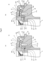
- Figs. 1(A), 1(B) and 1(C) are respectively a plan view, a bottom view, and a front view of a slide bearing 1 according to the present embodiment
- Fig. 1(D) is an A-A cross-section view of the slide bearing 1 shown in Fig. 1(A)
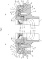
- Fig. 2 (A) is an enlarged view of the part A of the slide bearing 1 shown in Fig. 1(D)
- Fig. 2(B) is an enlarged view of the part B of the slide bearing 1 shown in Fig. 1(D) .
- the slide bearing 1 of the present embodiment has a receiving hole 10 for receiving a strut assembly (not shown) of a strut type suspension, and supports a load of a vehicle body applied to the strut type suspension while allowing rotation of the strut assembly received in the receiving hole 10.
- the slide bearing 1 comprises: an upper case 2; a lower case 3 which is rotatably combined with the upper case 2, to form a ring-shaped space 5 between the lower case 3 and the upper case 2; a dust-seal-integrated center plate 4 which is placed in the ring-shaped space 5; and a lubricating sheet 6 which is placed between the upper case 2 and the dust-seal-integrated center plate 4; and, although not shown, lubricating grease which is filled in the ring-shaped space 5.
- the upper case 2 is formed of thermoplastic resin superior in sliding characteristics such as polyacetal resin impregnated with lubricating oil as needed.
- the upper case 2 is mounted on an upper support (not shown) as a mounting mechanism for the strut assembly of the strut type suspension onto the vehicle body in a state that the strut assembly is inserted in the upper case 2.
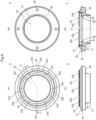
- Figs. 3(A), 3(B), and 3(C) are respectively a plan view, a bottom view, and a front view of the upper case 2, and Fig. 3 (D) is a B-B cross-section view of the upper case shown in Fig. 3(A) .
- the upper case 2 comprises: a ring-shaped upper case body 21 having an insertion hole 20 for inserting the strut assembly; an attaching surface 23 which is formed in the upper surface 22 of the upper case body 21 for attaching to the upper support; a ring-shaped groove 25 which is formed in the lower surface 24 of the upper case body 21 facing the lower case 3, to form a ring-shaped space 5 when the upper case 2 is rotatably combined with the lower case 3; a ring-shaped support object surface 27 which is formed in the groove bottom 26 of the ring-shaped groove 25 and rotates relative to a thrust bearing surface 402 (See Fig. 5 ) of the below-mentioned thrust bearing part 40 of the dust-seal-integrated center plate 4; and a snap fit part 29 for fitting the upper case 2 to the lower case 3.
- a thrust bearing surface 402 See Fig. 5
- the snap fit part 29 has a cylindrical shape extending toward the lower case 3 along the direction of the axis O on the inner side (inner diameter side) from the below-mentioned inner peripheral surface 37 (See Fig. 4 ) of the lower case 3.
- the end portion 291 of the snap fit part 29 protrudes outward in the radial direction, to engage with an engaging portion 38 (See Fig. 4 ) of the lower case 3.
- the end portion 291 of the snap fit part 29 protrudes outermost toward the lower case 3, on the side of the lower surface 24 of the upper case 2.
- a ring-shaped protective wall 28 is formed on the outer peripheral side of the support object surface 27, to protrude in the direction of the lower surface 24 from the groove bottom 26.
- This protective wall 28 encloses the outer peripheral side of the thrust bearing part 40 of the dust-seal-integrated center plate 4 placed in the ring-shaped space 5.
- the protective wall 28 prevents the lubricating grease filled in the ring-shaped space 5 from being pushed outward in the radial direction from the thrust bearing surface 402 of the thrust bearing part 40 of the dust-seal-integrated center plate 4.
- the lower case 3 is a resin body molded of thermoplastic resin such as polyamide . And the lower case 3 is fixed to an upper spring seat (not shown) as a spring seat for the upper end of a coil spring (not shown) of the strut type suspension in a state that the strut assembly of the strut type suspension is inserted in the lower case 3.
- Figs. 4 (A), 4 (B), and 4 (C) are respectively a plan view, a bottom view, and a front view of the lower case 3, and Fig. 4(D) is a C-C cross-section view of the lower case 3 shown in Fig. 4(A) .
- the lower case 3 comprises: a ring-shaped lower case body 31 having an insertion hole 30 for inserting the strut assembly; a ring-shaped projection 33 which is formed on the upper surface 32 of the lower case body 31 facing the upper case 2, and is inserted into the ring-shaped groove 25 formed in the lower surface 24 of the upper case body 21 of the upper case 2 to form the ring-shaped space 5, when the lower case 3 is rotatably combined with the upper case 2; and a ring-shaped mud guard 35 which protrudes outward in the radial direction from the outer peripheral surface 34 of the lower case body 31.
- a mounting surface 331 is formed for mounting the thrust bearing part 40 of the dust-seal-integrated center plate 4.
- a plurality of arc-shaped rotation locks 332 are formed at regular intervals in the circumferential direction.
- the rotation locks 332 engage with the below-mentioned connecting parts 43 (See Fig. 5 ) of the dust-seal-integrated center plate 4, to prevent rotation of the dust-seal-integrated center plate 4.
- the rotation locks 332 abut against the outer peripheral side of the thrust bearing part 40 of the dust-seal-integrated center plate 4, to prevent deformation in the radially outward direction of the thrust bearing part 40.
- rotation locks 332 are provided. However, it is sufficient to provide the rotation locks 332 equal in number to the connecting parts 43 of the dust-seal-integrated center plate 4. In that case, it is favorable that the arc lengths of the rotation locks 332 are adjusted so that gaps 334 in which the connecting parts 43 are placed become equal in width.
- the mud guard 35 protrudes from the outer peripheral surface 34 of the lower case body 31 outward in the radial direction beyond the outer peripheral surface 250 of the ring-shaped groove 25 of the upper case 2.
- the upper spring seal is fixed to the lower surface 36 of the mud guard 35.
- the engaging portion 38 is formed so as to engage with the end portion 291 of the snap fit part 29 of the upper case 2.
- the dust-seal-integrated center plate 4 is formed of elastic material superior in sliding characteristics such as polyolefin-based thermoplastic elastomer, polyester-based thermoplastic elastomer, polyurethane-based thermoplastic elastomer, polyamide-based thermoplastic elastomer, or the like, and is added with lubricant such as polytetrafluoroethylene (PTFE), lubricating oil, silicone, or the like as needed.
- PTFE polytetrafluoroethylene
- the dust-seal-integrated center plate 4 supports the load of the vehicle body which is applied to the strut type suspension and transmitted to the upper case 2, while allowing free rotation between the upper case 2 and the lower case 3. Further, the dust-seal-integrated center plate 4 closes the gap leading to the outside of the ring-shaped space 5, to prevent intrusion of foreign matters such as dust into the ring-shaped space 5.
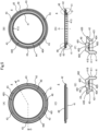
- Figs. 5(A), 5(B), and 5(C) are respectively a plan view, a bottom view, and a front view of the dust-seal-integrated center plate 4
- Fig. 5(D) is a D-D cross-section view of the dust-seal-integrated center plater 4 shown in Fig. 5(A)
- Fig. 5(E) is an enlarged view of the part C of the dust-seal-integrated center plate 4 shown in Fig. 5(D)
- Fig. 5(F) is an enlarged view of the part D of the dust-seal-integrated center plate 4 shown in Fig. 5(D) .
- the dust-seal-integrated center plate 4 comprises: a ring-shaped thrust bearing part 40; a cylindrical radial bearing part 41 which is formed integrally with the thrust bearing part 40, to protrude downward in the axial direction from the inner peripheral edge of the thrust bearing part 40; a cylindrical outer dust seal part 42 which is positioned on the outer peripheral side of the thrust bearing part 40; and the connecting parts 43 which connect the thrust bearing part 40 and the outer dust seal part 42.
- the thrust bearing part 40 comprises: a thrust bearing surface 402 formed in the upper surface 401; and a ring-shaped grease groove 403 which is formed in the thrust bearing surface 402 and functions as a grease reservoir.
- the radial bearing part 41 comprises: a radial bearing surface 411 formed in the inner peripheral surface 410; and grease grooves 413 in the direction of the axis O which are formed in the radial bearing surface 411 and function as grease reservoirs.
- one end 420 in the axial direction abuts against the protective wall 28 formed to protrude downward from the groove bottom 26 of the ring-shaped groove 25 of the upper case 2, and the other end 421 in the axial direction abuts against the upper surface 330 of the ring-shaped projection 33 of the lower case 3.
- the gap leading to the outside of the ring-shaped space 5 is closed, to prevent intrusion of foreign matters such as dust into the ring-shaped space 5.
- the outer dust seal part 42 is formed to be thinner than the thrust bearing part 40 and the radial bearing part 41, and the one end 420 which abuts against the upper case 2 is inclined outward in the radial direction seen in the axial cross-section. Accordingly, the one end 420 of the outer dust seal part 42 comes in contact with the protective wall 28 of the ring-shaped groove 25 of the upper case 2, while being deflected (See Fig. 2 ). The reaction force of the outer dust seal part 42 acting against the load of the vehicle body applied to the strut type suspension gives sufficient sealing performance to close the gap leading to the outside of the ring-shaped space 5.
- the connecting parts 43 extend outward in the radial direction from the outer peripheral side of the thrust bearing part 40, to connect with the outer dust seal part 42. Further, the connecting parts 43 have narrower width in the circumferential direction than the gaps 334 between the rotation locks 332 themselves formed on the mounting surface 331 of the ring-shaped projection 33 of the lower case body 31 of the lower case 3. And the connecting parts 43 are positioned in the respective gaps 334, to place the thrust bearing part 40 on the mounting surface 331. By engagement of the connecting parts 43 with the respective rotation locks 332 in the circumferential direction, the dust-seal-integrated center plate 4 is prevented from rotating. Although six connecting parts 43 are provided in the present embodiment, it is sufficient to provide at least one connecting part 43.
- the lubricating sheet 6 is formed of thermoplastic material superior in sliding characteristics such as fluorine resin (such as PTFE, modified PTFE obtained by copolymerizing tetrafluoroethylene (TFE) with a small amount of another material (comonomer), or the like), polyacetal resin, polyethylene resin, polyamide resin, polyphenylene sulfide resin, or the like, and, as needed, is added with lubricant such as PTFE (excepting the case where the thermoplastic material is PTFE or modified PTFE), lubricant such as lubricating oil, silicone, or graphite, and/or reinforcing material such as aramid fiber, glass fiber, carbon fiber, or the like.
- fluorine resin such as PTFE, modified PTFE obtained by copolymerizing tetrafluoroethylene (TFE) with a small amount of another material (comonomer), or the like
- polyacetal resin polyethylene resin, polyamide resin, polyphenylene sulf
- the lubricating sheet 6 is formed of metal superior in sliding characteristics such as brass alloy.
- the lubricating sheet 6 is a ring-shaped member, and is placed between the support object surface 27 formed in the groove bottom 26 of the ring-shaped groove 25 of the upper case 2 and the thrust bearing surface 402 of the thrust bearing part 40 of the dust-seal-integrated center plate 4. Owing to this arrangement, the thrust bearing surface 402 can rotate relative to the support object surface 27 via the lubricating sheet 6.
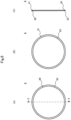
- Figs. 6(A) and 6(B) are respectively a plan view and a bottom view of the lubricating sheet 6, and Fig. 6(C) is an E-E cross-section view of the lubricating sheet 6 shown in Fig. 6(A) .
- the lubricating sheet 6 comprises: a sliding surface 62 which is formed in the upper surface 60, to slide on the support object surface 27 formed in the groove bottom 26 of the ring-shaped groove 25 of the upper case 2; and a sliding surface 63 which is formed in the lower surface 61, to slide on the thrust bearing surface 402 of the thrust bearing part 40 of the dust-seal-integrated center plate 4.
- the thickness of the lubricating sheet 6 depends on the material used, and, for example, 0.1 mm - 1 mm, and favorably 0.2 mm - 0.7 mm. Further, it is favorable that the lubricating sheet 6 is flat in both the front and back surfaces.
- the thrust bearing part 40 of the dust-seal-integrated center plate 4 is mounted on the mounting surface 331 of the ring-shaped projection 33 of the lower case 33, in a state that the dust-seal-integrated center plate 4 is prevented from rotating owing to engagement of the connecting parts 43 in the circumferential direction with the rotation locks 332 formed on the mounting surface 331. And the thrust bearing surface 402 of the thrust bearing part 40 rotates relative to the support object surface 27 of the ring-shaped groove 25 of the upper case 2 via the lubricating sheet 6.
- the radial bearing part 41 is inserted into the inside of the ring-shaped projection 33, and the radial bearing surface 411 of the radial bearing part 41 slides on the inner peripheral surface 251 of the ring-shaped groove 25 of the upper case 2. Accordingly, the dust-seal-integrated center plate 4 is supported by the upper spring seat fixed to the lower surface 36 of the mud guard 35 of the lower case 3 and by the coil spring of the strut type suspension, and thus supports the load of the vehicle body applied to the strut type suspension which is transmitted to the upper case 4, while allowing rotation between the upper case 2 and the lower case 3.
- the dust-seal-integrated center plate 4 is placed in the ring-shaped space 5 formed by combining the upper case 2 with the lower case 3 such that the one end 420 in the axial direction of the outer dust seal part 42 abuts against the protective wall 28 in the ring-shaped groove 25 of the upper case 2 and the other end 421 in the axial direction abuts against the upper surface 330 of the ring-shaped projection 33 of the lower case 3.
- the reaction force of the outer dust seal part 42 acting against the load of the vehicle body applied to the strut type suspension gives sufficient sealing performance to close the gap leading to the outside of the ring-shaped space 5, without embedding a metal core in the outer dust seal part 42 to increase the rigidity.
- the outer dust seal part 42 is connected to the thrust bearing part 40 via the connecting parts 43 extending outward in the radial direction from the outer peripheral side of the thrust bearing part 40, and the outer dust seal part 42 is formed integrally with the thrust bearing part 40. Accordingly, it is not necessary to provide the outer dust seal part 42 as a separate part, and, as a result, cost can be reduced.
- the lubricating sheet 6 is placed between the thrust bearing surface 402 of the thrust bearing part 40 and the support object surface 27 of the ring-shaped groove 25 of the upper case 2. Accordingly, even if elastomer is used as the material of the dust-seal-integrated center plate 4 to give elasticity to the outer dust seal part 42, it is possible to realize superior sliding performance.
- the dust-seal-integrated center plate 4 is provided with the cylindrical radial bearing part 41 formed integrally with the thrust bearing part 40, to protrude downward in the axial direction from the inner peripheral edge of the thrust bearing part 40, so that the radial bearing surface 411 slides on the inner peripheral surface 251 of the ring-shaped groove 25 of the upper case 2.
- the present embodiment it is possible to support the load in the radial direction in addition to the load of the vehicle body in the thrust direction, while allowing rotation between the upper case 2 and the lower case 3.
- the ring-shaped grease groove 403 functioning as a grease reservoir is formed in the thrust bearing surface 402 of the thrust bearing part 40. Accordingly, it is possible to hold more lubricating grease on the thrust bearing surface 402. As a result, according to the present invention, the thrust bearing surface 402 is covered with lubricating grease film, and it is possible to support over a longer period of time the load of the vehicle body applied to the strut type suspension, while allowing smooth rotation of the strut assembly of the strut type suspension.
- the ring-shaped recess 405 is formed at the position opposite to the grease groove 403 of the thrust bearing surface. Accordingly, it is possible to prevent that force applied from the mounting surface 331 of the ring-shaped projection 33 of the lower case 3 to the thrust bearing part 40 raises the groove bottom of the grease groove 403 of the thrust bearing surface 402 toward the upper case 2. As a result, according to the present embodiment, it is possible to prevent the grease in the grease groove 403 from overflowing from the grease groove 403, and thereby to keep the grease in the grease groove 403 and to maintain the sliding performance for a longer period.
- the arc-shaped rotation locks 332 are formed on the outer peripheral side of the mounting surface 331 formed in the upper surface 330 of the ring-shaped projection 33 of the lower case 3. These rotation locks 332 engages in the circumferential direction with the respective connecting parts 43 of the dust-seal-integrated center plate 4, to prevent rotation of the dust-seal-integrated center plate 4. And at the same time, the rotation locks 332 abut against the outer peripheral side of the thrust bearing part 40 of the dust-seal-integrated center plate 4, to prevent deformation of the thrust bearing part 40 outward in the radial direction owing to the load of the vehicle body applied to the strut type suspension.
- the lower case 3 is provided with the ring-shaped mud guard 35, which protrudes from the outer peripheral surface 34 of the lower case body 31 on the side of the upper surface 32 of the lower case body 31 and outward in the radial direction beyond the outer peripheral surface 250 of the ring-shaped groove 25 of the upper case 2. Accordingly, the mud guard 35 can prevent muddy water or the like which jumps into the vehicle body from road surface while the vehicle is moving, so as to prevent more efficiently intrusion of the muddy water or the like into the ring-shaped space 5 of the slide bearing 1.
- the snap fit part 29 which has the cylindrical shape extending toward the lower case 3 along the direction of the axis O and whose end portion 291 engages with the engaging portion 38 of the lower case 3 is formed on the inner peripheral side of the upper case 2 (on the inner side from the inner peripheral surface 37 of the lower case 3).
- the end portion 291 of the snap fit part 29 protrudes outward in the radial direction and protrudes outermost toward the lower case 3 on the side of the lower surface 24 of the upper case 2.
- the present embodiment it is possible to simplify the structure of the mold required for resin molding of the upper case 2, in comparison with the case where a snap fit part is provided on the outer peripheral side of the upper case 2 and the end portion of the snap fit part is made to protrude inward in the radial direction.
- a snap fit part is provided on the outer peripheral side of the upper case 2 such that the end portion of the snap fit part protrudes inward in the radial direction
- the ring-shaped protective wall 28 is provided in the groove bottom 26 of the ring-shaped groove 25 of the upper case, to enclose the outer peripheral side of the thrust bearing part 40 of the dust-seal-integrated center plate 4 placed in the ring-shaped space 5 formed by combining the upper case 2 with the lower case 3. Owing to this protective wall 28, it is possible to prevent the lubricating grease filled in the ring-shaped space 5 from being pushed outward in the radial direction from the thrust bearing surface 402 of the thrust bearing part 40, when the load is applied to the strut type suspension. Accordingly, the thrust bearing surface 402 can be covered with the lubricating grease more reliably. Thus, according to the present embodiment, it is possible to support over a longer period of time the load of the vehicle body applied to the strut type suspension while allowing smooth rotation of the strut assembly of the strut type suspension.
- the dust-seal-integrated center plate 4 is placed in the ring-shaped space 5 which is formed by combining the upper case 2 with the lower case 3, such that the one end 420 in the axial direction of the outer dust seal part 42 abuts against the protective wall 28 in the ring-shaped groove 25 of the upper case 2 and the other end 421 in the axial direction abuts against the upper surface 330 of the ring-shaped projection 33 of the lower case 3.
- the present invention is not limited to this.
- the dust-seal-integrated center plate 4 is placed in the ring-shaped space 5 such that the one end 420 in the axial direction of the outer dust seal part 42 is abutted against the protective wall 28 in the ring-shaped groove 25 of the upper case 2.
- the thrust bearing part 40 formed integrally with the outer dust seal part 42 is fixed on the mounting surface 331 of the ring-shaped projection 33 of the lower case 3, sufficient sealing performance to close the gap leading to the outside of the ring-shaped space 5 can be obtained by reaction force generated by deflection of the outer dust seal part 42.
- the other end 421 in the axial direction can be omitted.
- a plurality of lubricating sheets 6 may be placed to overlap each other between the support object surface 27 and the thrust bearing surface 402.
- a plurality of lubricating sheets 6 are laid to overlap each other and slide on each other, it is possible to shorten slide lengths between the lubricating sheet 6 themselves, between the support object surface 27 and the lubricating sheet 6, and between the thrust bearing surface 402 and the lubricating sheet 6, and this decreases abrasion at each sliding location and extends lifetime.
- this recess is set to the thickness of lubricating sheet 6 or more, for example.
- a lubricating sheet may be placed also between the radial bearing surface 411 of the radial bearing part 41 and the inner peripheral surface 251 of the ring-shaped groove 25 of the upper case 2.
- a lubricating sheet 6a which is formed such that a ring-shaped thrust sheet part 64 is integrated with a radial sheet part 65.
- the thrust sheet part 64 is positioned between the thrust bearing surface 402 of the thrust bearing part 40 and the support object surface 27 of the ring-shaped groove 25 of the upper case 2.
- the radial sheet part 65 is formed integrally with the inner peripheral edge of the thrust sheet part 64 and is positioned between the radial bearing surface 411 of the radial bearing part 41 and the inner peripheral surface 251 of the ring-shaped groove 25 of the upper case 2. This arrangement can realize more superior sliding performance.
- the rotation locks 332 are formed on the outer peripheral side of the mounting surface 331 formed in the upper surface 330 of the ring-shaped projection 33 of the lower case 3.
- the present invention is not limited to this. It is possible to form rotation locks on the outer peripheral side of the support object surface 27 formed in the groove bottom 26 of the ring-shaped groove 25 of the upper case 2, and to make these rotation locks to engage with the connecting parts 43 of the dust-seal-integrated center plate 4, so as to prevent rotation of the dust-seal-integrated center plate 4.
- these rotation locks may be abuts against the outer peripheral side of the thrust bearing part 40 of the dust-seal-integrated center plate 4, to prevent deformation of the thrust bearing part 40 outward in the radial direction owing to the load of the vehicle body applied to the strut type suspension.
- a thrust bearing surface is formed in the lower surface 404 of the thrust bearing part 40, and this thrust bearing surface is made to come in slidable contact with the mounting surface 331 of the ring-shaped projection 33 of the lower case 3.
- the one end 420 in the axial direction of the outer dust seal part 42 of the dust-seal-integrated center plate 4 is made to abut against the protective wall 28 which is formed to protrude downward from the groove bottom 26 of the ring-shaped groove 25 of the upper case 2, in order to abut against the groove bottom 26 of the ring-shaped groove 25.
- the present invention is not limited to this.
- the one end 420 of the outer dust seal part 42 may be directly abutted against the groove bottom 26 of the ring-shaped groove 25.
- the one end 420 of the outer dust seal part 42 which abuts on the side of the groove bottom 26 of the ring-shaped groove 25 of the upper case 2 is inclined outward in the radial direction seen in the axial cross-section of the dust-seal-integrated center plate 4 (See Fig. 2 ).
- the present invention is not limited to this. It is sufficient that, seen in the axial cross-section, at least one of both the ends 420 and 421 of the outer dust seal part 42 is inclined outward or inward in the axial direction.
- a dust seal may be added to close this gap 50.
- a dust seal may be added to close this gap 50.
- a dust-seal-integrated center plate 4c with which an inner dust seal part 44 to close the gap 50 leading to the ring-shaped space 5 is formed integrally at the end 412 of the radial bearing part 41 on the side of the lower case 3.
- a grease groove functioning as a grease reservoir may be formed also in the radial bearing surface 411 of the radial bearing part 41.
- a dust-seal-integrated center plate 4d having a radial bearing part 41a whose radial bearing surface 411 has a ring-shaped grease groove 413 functioning as a grease reservoir formed therein.
- the dust-seal-integrated center plate 4 is placed and fixed on the lower case 3.
- the dust-seal-integrated center plate 4 may be placed rotatably on the lower case 3.
- a thrust bearing surface may be formed also in the lower surface 404 of the thrust bearing part 40, so that this thrust bearing surface comes in slidable contact with the mounting surface 331 of the ring-shaped projection 33 of the lower case 3.
- the rotation locks 332 positioned on the outer peripheral side of the mounting surface 331 of the ring-shaped projection 33 are omitted.
- the recess 405 is not needed in the lower surface 404 of the thrust bearing part 40.
- a grease groove may be formed also in this thrust bearing surface.
- at least one lubricating sheet 6 may be placed also between the thrust bearing surface formed in the lower surface 404 of the thrust bearing part 40 and the mounting surface 331 of the ring-shaped projection 33 of the lower case 3. Further, it is favorable that both the ends 420 and 421 of the outer dust seal part 42 of the dust-seal-integrated center plate 4 are inclined, so that both the ends 420 and 421 are respectively abutted against the groove bottom 26 of the ring-shaped groove 25 of the upper case 2 and the upper surface 330 of the ring-shaped projection 33 of the lower case 3.
- the dust-seal-integrated center plate 4 may be formed integrally with the lower case 3. In this case, it is not necessary to form the arc-shaped rotational locks 332 on the outer peripheral side of the mounting surface 331 of the lower case 3. Further, in the ring-shaped space 5 formed by combining the upper case 2 with the lower case 3, the dust-seal-integrated center plate 4 formed integrally with the lower case 3 is positioned in the ring-shaped space 5 such that the one end 420 in the axial direction of the outer dust seal part 42 abuts against the groove bottom 26 including the protective wall 28 in the ring-shaped groove 25 of the upper case 2.
- the dust-seal-integrated center plate 4 may be formed integrally with the upper case 2. In this case also, it is not necessary to form the arc-shaped rotation locks 332 on the outer peripheral side of the mounting surface 331 of the lower case 3. Further, the lubricating sheet 6 is placed between the dust-seal-integrated center plate 4 formed integrally with the upper case 2 and the mounting surface 331 of the ring-shaped projection 33 of the lower case 3.
- the dust-seal-integrated center plate 4 formed integrally with the upper case 2 is positioned in the ring-shaped space 5 such that the other end 421 in the axial direction of the outer dust seal part 42 abuts against the upper surface 330 of the ring-shaped projection 33 of the lower case 3.
- the ring-shaped recess 405 is formed at the position opposite to the grease groove 403 of the thrust bearing surface 402 in the lower surface 404 on the opposite side to the upper surface 401.
- the present invention is not limited to this.
- the lower surface 404 of the thrust bearing part 40 may be a flat surface.
- similar effects to those of the above embodiment can be obtained except for the effect owing to the ring-shaped recess 405.
- a ring-shaped recess may be provided in the mounting surface 331 of the ring-shaped projection 33 of the lower case. In this case, similar effects to those of the above embodiment can be obtained.
- the slide bearing of the present embodiment is applied to the strut type suspension.
- the present invention is limited to the scope defined by the appended claims.
- the slide bearing of the present invention can be widely applied to slide bearings which support load while allowing rotation in various mechanisms including a double wishbone type suspension, a multilink type suspension, an air suspension, or the like.
- 1, 1a - 1g slide bearing; 2: upper case; 3: lower case; 4, 4a - 4d: dust-seal-integrated center plate; 5: ring-shaped space; 6, 6a: lubricating sheet; 10: receiving hole for the slide bearing 1; 20: insertion hole of the upper case 2; 21: upper case body; 22: upper surface of the upper case body 21; 23: attaching surface of the upper case body 21; 24: lower surface of the upper case body 21; 25: ring-shaped groove of the upper case body 21; 26: groove bottom of the ring-shaped groove 25; 27: support object surface of the upper case body 21; 28: protective wall of the upper case body 21; 29: snap fit part; 30: insertion hole of the lower case 3; 31: lower case body; 32: upper surface of the lower case body 31; 33: ring-shaped projection of the lower case body 31; 34: outer peripheral surface of the lower case body 31; 35: mud guard; 36: lower surface of the mud guard 35; 37: inner peripheral surface of the lower case
Landscapes
- Engineering & Computer Science (AREA)
- General Engineering & Computer Science (AREA)
- Mechanical Engineering (AREA)
- Sealing Of Bearings (AREA)
- Vehicle Body Suspensions (AREA)
- Sliding-Contact Bearings (AREA)
- Fluid-Damping Devices (AREA)
Claims (13)
- Gleitlager, umfassend:ein oberes Gehäuse (2) mit einer ringförmigen Rille (25), die in einer unteren Fläche (24) eines oberen Gehäusekörpers (21) des oberen Gehäuses ausgebildet ist;ein unteres Gehäuse (3), das drehbar mit dem oberen Gehäuse kombiniert ist und einen ringförmigen unteren Gehäusekörper (31) mit einem Einführungsloch zum Einfügen der Federbeinanordnung aufweist und einen ringförmigen Vorsprung (33) aufweist, der in einer oberen Fläche (32) des unteren Gehäuses, die dem oberen Gehäuse zugewandt ist, ausgebildet ist und in die ringförmige Nut eingesetzt ist, die in der unteren Fläche, die dem unteren Gehäuse zugewandt ist, ausgebildet ist, um einen ringförmigen Raum (5) zu bilden, wobei das untere Gehäuse einen ringförmigen Schlammschutz (35) aufweist, der in einer radialen Richtung von einer äußeren Umfangsfläche des unteren Gehäuses nach außen vorsteht;eine ringförmige Mittelplatte (4; 4a-d), die zwischen das obere Gehäuse und das untere Gehäuse platziert ist; undeine ringförmige äußere Staubdichtung (42), die auf einer äußeren Umfangsseite der Mittelplatte positioniert ist;wobeidas Gleitlager ferner ein ringförmiges Schmierblatt (6; 6a) umfasst, das zwischen die Mittelplatte und das obere Gehäuse und/oder zwischen die Mittelplatte und das untere Gehäuse platziert ist;die ringförmige äußere Staubdichtung ein Ende (420) in der axialen Richtung aufweist, das in der radialen Richtung nach außen geneigt ist und, während es gebogen wird, unmittelbar gegen einen Nutboden (26) der ringförmigen Nut des oberen Gehäuses oder gegen eine Schutzwand (28), die so ausgebildet ist, dass sie vom Nutboden der ringförmigen Nut des oberen Gehäuses nach unten vorsteht, anstößt, und ein anderes Ende (421) in der axialen Richtung aufweist, das gegen eine obere Fläche (330) des ringförmigen Vorsprungs des unteren Gehäuses anstößt;die Mittelplatte ein Verbindungsteil (43) aufweist, das sich in radialer Richtung von der äußeren Umfangsseite der Mittelplatte nach außen erstreckt und mit der äußeren Staubdichtung verbunden ist; undmindestens eine der Vorder- und Rückseitenflächen (60, 61) des Schmierblatts eine Gleitfläche (63) aufweist, die auf einer dem Schmierblatt zugewandten Gegenfläche gleitet.
- Gleitlager nach Anspruch 1, wobei:
der ringförmige Schlammschutz (35) in radialer Richtung von einer äußeren Umfangsfläche des unteren Gehäuses über eine äußere Umfangsfläche der ringförmigen Nut (25) des oberen Gehäuses (2) hinaus nach außen vorsteht. - Gleitlager nach Anspruch 1 oder 2, wobei:
das obere Gehäuse (2) ferner eine Ausnehmung aufweist, die in der ringförmigen Nut (25) des oberen Gehäuses zum Aufnehmen des Schmierblatts (6; 6a) ausgebildet ist. - Gleitlager nach einem der Ansprüche 1 bis 3, umfassend:
mehrere Schmierblätter (6; 6a), die gleitend übereinander gelegt sind. - Gleitlager nach einem der Ansprüche 1 bis 4, dadurch gekennzeichnet, dass:
die Mittelplatte (4; 4a-d) umfasst:ein ringförmiges Stoßlagerteil (40), das zwischen das obere Gehäuse (2) und das untere Gehäuse (3) in einer Stoßrichtung platziert ist; undein Radiallagerteil (41; 41a), das einstückig mit einer inneren Umfangskante des Stoßlagerteils ausgebildet und zwischen das obere Gehäuse und das untere Gehäuse in radialer Richtung platziert ist. - Gleitlager nach Anspruch 5, wobei:
das Schmierblatt (6a) umfasst:eine ringförmiges Stoßblatt (64), die zwischen das Stoßlagerteil (40) und das obere Gehäuse (2) und/oder zwischen das Stoßlagerteil und das untere Gehäuse (3) platziert ist; undein zylindrisches Radialblatt (65), das einstückig mit einer inneren Umfangskante des Stoßblatts ausgebildet ist und zwischen dem Radiallagerteil (41; 41a) und dem oberen Gehäuse und/oder zwischen dem Radiallagerteil und dem unteren Gehäuse positioniert ist. - Gleitlager nach Anspruch 5 oder 6, das ferner umfasst:
eine ringförmige innere Staubdichtung (44), die einstückig mit einem Ende des Radiallagerteils (41a) ausgebildet ist und gegen das obere Gehäuse (2) oder das untere Gehäuse (3) anstößt. - Gleitlager nach einem der Ansprüche 5 bis 7, dadurch gekennzeichnet, dass:
das Stoßlagerteil (40) eine ringförmige Schmiernut (403) aufweist, die in einer dem Schmierblatt (6; 6a) zugewandten Oberfläche ausgebildet ist und als ein Schmiermittelreservoir fungiert, wobei das Axiallagerteil optional ferner eine ringförmige Ausnehmung (405) aufweist, die in einer Oberfläche ausgebildet ist, die der Oberfläche mit der Schmiernut gegenüberliegt. - Gleitlager nach einem der Ansprüche 5 bis 8, umfassend:
eine Rotationssperre (332), die in einer Oberfläche des unteren Gehäuses (3), die dem oberen Gehäuse (2) zugewandt ist, oder in einer Oberfläche des oberen Gehäuses, die dem unteren Gehäuse zugewandt ist, ausgebildet ist und mit dem Verbindungsteil (43) des Stoßlagerteils (40) in einer Umfangsrichtung in Eingriff steht, um eine Rotation des Stoßlagerteils und der äußeren Staubdichtung (42) zu verhindern, und gegen eine äußere Umfangsseite des Stoßlagerteils anstößt, um eine Verformung des Stoßlagerteils nach außen in radialer Richtung zu verhindern. - Gleitlager nach einem der Ansprüche 5 bis 9, wobei:das Stoßlagerteil (40) auf dem ringförmigen Vorsprung (33) des unteren Gehäuses (3) angebracht ist und auf einer Stützobjektfläche, die in der dem unteren Gehäuse zugewandten Oberfläche des oberen Gehäuses ausgebildet ist, gleitet, um dadurch eine auf das obere Gehäuse (2) ausgeübte Last abzustützen, während Rotation zwischen dem oberen Gehäuse und dem unteren Gehäuse ermöglicht wird; unddie äußere Staubdichtung (42) auf einer äußeren Umfangsseite des ringförmigen Vorsprungs des unteren Gehäuses positioniert ist.
- Gleitlager nach einem der Ansprüche 1 bis 8, dadurch gekennzeichnet, dass:die Mittelplatte (4; 4a-d) einstückig mit dem unteren Gehäuse (3) ausgebildet ist, wobei das Schmierblatt (6; 6a) zwischen die Mittelplatte und das obere Gehäuse (2) platziert ist, oderdie Mittelplatte einstückig mit dem oberen Gehäuse (3) ausgebildet ist, wobei das Schmierblatt zwischen die Mittelplatte und das untere Gehäuse platziert ist.
- Gleitlager nach einem der Ansprüche 1 bis 11, wobei:das untere Gehäuse (3) ein ringförmiges Element mit einer inneren Umfangsfläche, die mit einem Eingriffsteil (38) versehen ist, ist;das obere Gehäuse (2) ein Schnapppassteil (29) aufweist, das sich entlang einer axialen Richtung zum unteren Gehäuse hin auf einer Innenseite von der inneren Umfangsfläche des unteren Gehäuses erstreckt, und ein Endabschnitt (291) des Schnapppassteils in der radialen Richtung nach außen vorsteht, um mit dem Eingriffsteil der inneren Umfangsfläche des unteren Gehäuses in Eingriff zu kommen; undder Endabschnitt des Schnapppassteils auf einer Seite der Oberfläche, die dem unteren Gehäuse zugewandt ist, am weitesten nach außen zum unteren Gehäuse hin vorsteht.
- Gleitlager nach einem der Ansprüche 1 bis 12, wobei:das Gleitlager eine auf eine Federbeinaufhängung wirkende Fahrzeuglast abstützt, während es die Rotation einer Federbeinanordnung der Federbeinaufhängung ermöglicht;das obere Gehäuse (2) in einem Zustand, in dem die Federbeinanordnung in das obere Gehäuse eingesetzt ist, an einem Befestigungsmechanismus zur Befestigung der Federbeinanordnung am Fahrzeugkörper angebracht ist; unddas untere Gehäuse (3) an einem Federsitz für ein oberes Ende einer mit der Federbeinanordnung kombinierten Schraubenfeder in einem Zustand befestigt ist, in dem die Federbeinanordnung in das untere Gehäuse eingesetzt ist.
Applications Claiming Priority (2)
| Application Number | Priority Date | Filing Date | Title |
|---|---|---|---|
| JP2016141651 | 2016-07-19 | ||
| PCT/JP2017/025998 WO2018016500A1 (ja) | 2016-07-19 | 2017-07-18 | 滑り軸受 |
Publications (3)
| Publication Number | Publication Date |
|---|---|
| EP3489535A1 EP3489535A1 (de) | 2019-05-29 |
| EP3489535A4 EP3489535A4 (de) | 2020-03-11 |
| EP3489535B1 true EP3489535B1 (de) | 2024-10-09 |
Family
ID=60992488
Family Applications (1)
| Application Number | Title | Priority Date | Filing Date |
|---|---|---|---|
| EP17831016.5A Active EP3489535B1 (de) | 2016-07-19 | 2017-07-18 | Gleitlager |
Country Status (6)
| Country | Link |
|---|---|
| US (1) | US10746224B2 (de) |
| EP (1) | EP3489535B1 (de) |
| JP (1) | JP6909789B2 (de) |
| KR (1) | KR102361216B1 (de) |
| CN (1) | CN109416078B (de) |
| WO (1) | WO2018016500A1 (de) |
Families Citing this family (7)
| Publication number | Priority date | Publication date | Assignee | Title |
|---|---|---|---|---|
| JP7177074B2 (ja) * | 2017-10-06 | 2022-11-22 | オイレス工業株式会社 | 滑り軸受 |
| JP7002366B2 (ja) * | 2018-03-06 | 2022-01-20 | オイレス工業株式会社 | サスペンション取付構造 |
| EP3892873B1 (de) * | 2020-04-10 | 2022-08-31 | Roller Bearing Company of America, Inc. | Innere und äussere dichtungsvorrichtung; axiallagervorrichtung mit solchen dichtungsvorrichtungen für wartungsfreien betrieb |
| KR102745134B1 (ko) * | 2020-06-03 | 2024-12-23 | 현대모비스 주식회사 | 차량용 회전유도장치 |
| FR3125463B1 (fr) * | 2021-07-23 | 2023-06-16 | Skf Svenska Kullagerfab Ab | Dispositif de butée de suspension à joint d’étanchéité |
| CN114087344B (zh) * | 2021-11-19 | 2023-09-01 | 广东华于科技股份有限公司 | 一种用于输出轴上的油封座 |
| KR102939794B1 (ko) * | 2022-07-15 | 2026-03-16 | 주식회사 일진 | 차량용 스트럿 베어링 어셈블리 |
Citations (1)
| Publication number | Priority date | Publication date | Assignee | Title |
|---|---|---|---|---|
| EP2679843A1 (de) * | 2011-02-23 | 2014-01-01 | Oiles Corporation | Kunstharz-axialgleitlager |
Family Cites Families (15)
| Publication number | Priority date | Publication date | Assignee | Title |
|---|---|---|---|---|
| US4503549A (en) | 1982-07-16 | 1985-03-05 | The Babcock & Wilcox Company | Interpolating function generator for transmitter square root extraction |
| JPS5927347U (ja) * | 1982-08-16 | 1984-02-20 | オイレス工業株式会社 | ストラツトスラスト軸受 |
| JPS60161737A (ja) | 1984-01-30 | 1985-08-23 | Hitachi Metals Ltd | ドラムフイ−ダ |
| JPS60161737U (ja) * | 1984-04-05 | 1985-10-26 | 日産自動車株式会社 | ストラツトスラスト軸受 |
| JP4288930B2 (ja) | 2002-10-03 | 2009-07-01 | オイレス工業株式会社 | 滑り軸受 |
| US7993061B2 (en) * | 2002-10-03 | 2011-08-09 | Oiles Corporation | Sliding bearing |
| CN101688878B (zh) | 2007-05-16 | 2011-06-22 | Ntn株式会社 | 结合有轮速检测装置的车轮轴承装置 |
| BR112012004313B1 (pt) * | 2009-10-06 | 2021-01-12 | Nsk Ltd | Suporte de unidade de cubo |
| JP5516210B2 (ja) | 2010-08-06 | 2014-06-11 | オイレス工業株式会社 | スラスト滑り軸受 |
| WO2012145610A1 (en) * | 2011-04-21 | 2012-10-26 | Illinois Tool Works Inc. | Sealing for thrust bearing |
| DE102013201965A1 (de) * | 2013-02-07 | 2014-08-07 | Schaeffler Technologies Gmbh & Co. Kg | Federbeinlager |
| JP5755277B2 (ja) | 2013-03-27 | 2015-07-29 | 東レプラスチック精工株式会社 | 軸受用受け皿およびその製造方法、ならびに軸受用受け皿を用いてなる軸受 |
| FR3014992B1 (fr) * | 2013-12-13 | 2017-09-22 | O S C Offshore Systems Concepts | Joint d'etancheite a levres elastiques |
| JP6326657B2 (ja) * | 2014-06-26 | 2018-05-23 | オイレス工業株式会社 | スラスト滑り軸受 |
| JP6479444B2 (ja) * | 2014-12-03 | 2019-03-06 | オイレス工業株式会社 | 滑り軸受およびストラット式サスペンション |
-
2017
- 2017-07-18 EP EP17831016.5A patent/EP3489535B1/de active Active
- 2017-07-18 JP JP2018528819A patent/JP6909789B2/ja active Active
- 2017-07-18 WO PCT/JP2017/025998 patent/WO2018016500A1/ja not_active Ceased
- 2017-07-18 CN CN201780039984.6A patent/CN109416078B/zh active Active
- 2017-07-18 KR KR1020197002510A patent/KR102361216B1/ko active Active
- 2017-07-18 US US16/318,834 patent/US10746224B2/en active Active
Patent Citations (1)
| Publication number | Priority date | Publication date | Assignee | Title |
|---|---|---|---|---|
| EP2679843A1 (de) * | 2011-02-23 | 2014-01-01 | Oiles Corporation | Kunstharz-axialgleitlager |
Also Published As
| Publication number | Publication date |
|---|---|
| EP3489535A4 (de) | 2020-03-11 |
| US10746224B2 (en) | 2020-08-18 |
| BR112019001017A2 (pt) | 2019-05-14 |
| JPWO2018016500A1 (ja) | 2019-05-09 |
| EP3489535A1 (de) | 2019-05-29 |
| WO2018016500A1 (ja) | 2018-01-25 |
| JP6909789B2 (ja) | 2021-07-28 |
| US20190277336A1 (en) | 2019-09-12 |
| KR102361216B1 (ko) | 2022-02-10 |
| CN109416078B (zh) | 2021-02-02 |
| KR20190031247A (ko) | 2019-03-25 |
| CN109416078A (zh) | 2019-03-01 |
Similar Documents
| Publication | Publication Date | Title |
|---|---|---|
| EP3489535B1 (de) | Gleitlager | |
| EP3404275B1 (de) | Gleitlager | |
| EP2428693B1 (de) | Gleitlager | |
| CN107110201B (zh) | 滑动轴承支柱型悬架 | |
| CN111133208B (zh) | 滑动轴承 | |
| WO2019116887A1 (ja) | 滑り軸受 | |
| JP6581448B2 (ja) | 滑り軸受 | |
| EP3141769B1 (de) | Schubgleitlager | |
| EP3401561B1 (de) | Gleitlager | |
| JP7105697B2 (ja) | 滑り軸受 | |
| JP7288759B2 (ja) | 滑り軸受 | |
| JP7111745B2 (ja) | 滑り軸受 | |
| JP2019124291A (ja) | 滑り軸受 |
Legal Events
| Date | Code | Title | Description |
|---|---|---|---|
| STAA | Information on the status of an ep patent application or granted ep patent |
Free format text: STATUS: THE INTERNATIONAL PUBLICATION HAS BEEN MADE |
|
| PUAI | Public reference made under article 153(3) epc to a published international application that has entered the european phase |
Free format text: ORIGINAL CODE: 0009012 |
|
| STAA | Information on the status of an ep patent application or granted ep patent |
Free format text: STATUS: REQUEST FOR EXAMINATION WAS MADE |
|
| 17P | Request for examination filed |
Effective date: 20190125 |
|
| AK | Designated contracting states |
Kind code of ref document: A1 Designated state(s): AL AT BE BG CH CY CZ DE DK EE ES FI FR GB GR HR HU IE IS IT LI LT LU LV MC MK MT NL NO PL PT RO RS SE SI SK SM TR |
|
| AX | Request for extension of the european patent |
Extension state: BA ME |
|
| DAV | Request for validation of the european patent (deleted) | ||
| DAX | Request for extension of the european patent (deleted) | ||
| A4 | Supplementary search report drawn up and despatched |
Effective date: 20200210 |
|
| RIC1 | Information provided on ipc code assigned before grant |
Ipc: F16C 17/10 20060101ALI20200204BHEP Ipc: F16C 33/20 20060101ALI20200204BHEP Ipc: B60G 15/06 20060101ALI20200204BHEP Ipc: F16C 33/74 20060101AFI20200204BHEP Ipc: F16C 33/10 20060101ALI20200204BHEP Ipc: F16C 17/04 20060101ALI20200204BHEP |
|
| STAA | Information on the status of an ep patent application or granted ep patent |
Free format text: STATUS: EXAMINATION IS IN PROGRESS |
|
| 17Q | First examination report despatched |
Effective date: 20210326 |
|
| GRAP | Despatch of communication of intention to grant a patent |
Free format text: ORIGINAL CODE: EPIDOSNIGR1 |
|
| STAA | Information on the status of an ep patent application or granted ep patent |
Free format text: STATUS: GRANT OF PATENT IS INTENDED |
|
| INTG | Intention to grant announced |
Effective date: 20240627 |
|
| RAP3 | Party data changed (applicant data changed or rights of an application transferred) |
Owner name: OILES CORPORATION |
|
| GRAJ | Information related to disapproval of communication of intention to grant by the applicant or resumption of examination proceedings by the epo deleted |
Free format text: ORIGINAL CODE: EPIDOSDIGR1 |
|
| STAA | Information on the status of an ep patent application or granted ep patent |
Free format text: STATUS: EXAMINATION IS IN PROGRESS |
|
| GRAP | Despatch of communication of intention to grant a patent |
Free format text: ORIGINAL CODE: EPIDOSNIGR1 |
|
| STAA | Information on the status of an ep patent application or granted ep patent |
Free format text: STATUS: GRANT OF PATENT IS INTENDED |
|
| GRAS | Grant fee paid |
Free format text: ORIGINAL CODE: EPIDOSNIGR3 |
|
| INTC | Intention to grant announced (deleted) | ||
| GRAA | (expected) grant |
Free format text: ORIGINAL CODE: 0009210 |
|
| STAA | Information on the status of an ep patent application or granted ep patent |
Free format text: STATUS: THE PATENT HAS BEEN GRANTED |
|
| INTG | Intention to grant announced |
Effective date: 20240812 |
|
| AK | Designated contracting states |
Kind code of ref document: B1 Designated state(s): AL AT BE BG CH CY CZ DE DK EE ES FI FR GB GR HR HU IE IS IT LI LT LU LV MC MK MT NL NO PL PT RO RS SE SI SK SM TR |
|
| REG | Reference to a national code |
Ref country code: CH Ref legal event code: EP |
|
| REG | Reference to a national code |
Ref country code: DE Ref legal event code: R096 Ref document number: 602017085404 Country of ref document: DE |
|
| REG | Reference to a national code |
Ref country code: IE Ref legal event code: FG4D |
|
| REG | Reference to a national code |
Ref country code: LT Ref legal event code: MG9D |
|
| REG | Reference to a national code |
Ref country code: NL Ref legal event code: MP Effective date: 20241009 |
|
| REG | Reference to a national code |
Ref country code: AT Ref legal event code: MK05 Ref document number: 1730887 Country of ref document: AT Kind code of ref document: T Effective date: 20241009 |
|
| PG25 | Lapsed in a contracting state [announced via postgrant information from national office to epo] |
Ref country code: NL Free format text: LAPSE BECAUSE OF FAILURE TO SUBMIT A TRANSLATION OF THE DESCRIPTION OR TO PAY THE FEE WITHIN THE PRESCRIBED TIME-LIMIT Effective date: 20241009 |
|
| PG25 | Lapsed in a contracting state [announced via postgrant information from national office to epo] |
Ref country code: NL Free format text: LAPSE BECAUSE OF FAILURE TO SUBMIT A TRANSLATION OF THE DESCRIPTION OR TO PAY THE FEE WITHIN THE PRESCRIBED TIME-LIMIT Effective date: 20241009 |
|
| PG25 | Lapsed in a contracting state [announced via postgrant information from national office to epo] |
Ref country code: HR Free format text: LAPSE BECAUSE OF FAILURE TO SUBMIT A TRANSLATION OF THE DESCRIPTION OR TO PAY THE FEE WITHIN THE PRESCRIBED TIME-LIMIT Effective date: 20241009 Ref country code: IS Free format text: LAPSE BECAUSE OF FAILURE TO SUBMIT A TRANSLATION OF THE DESCRIPTION OR TO PAY THE FEE WITHIN THE PRESCRIBED TIME-LIMIT Effective date: 20250209 Ref country code: PT Free format text: LAPSE BECAUSE OF FAILURE TO SUBMIT A TRANSLATION OF THE DESCRIPTION OR TO PAY THE FEE WITHIN THE PRESCRIBED TIME-LIMIT Effective date: 20250210 |
|
| PG25 | Lapsed in a contracting state [announced via postgrant information from national office to epo] |
Ref country code: FI Free format text: LAPSE BECAUSE OF FAILURE TO SUBMIT A TRANSLATION OF THE DESCRIPTION OR TO PAY THE FEE WITHIN THE PRESCRIBED TIME-LIMIT Effective date: 20241009 |
|
| PG25 | Lapsed in a contracting state [announced via postgrant information from national office to epo] |
Ref country code: BG Free format text: LAPSE BECAUSE OF FAILURE TO SUBMIT A TRANSLATION OF THE DESCRIPTION OR TO PAY THE FEE WITHIN THE PRESCRIBED TIME-LIMIT Effective date: 20241009 |
|
| PG25 | Lapsed in a contracting state [announced via postgrant information from national office to epo] |
Ref country code: ES Free format text: LAPSE BECAUSE OF FAILURE TO SUBMIT A TRANSLATION OF THE DESCRIPTION OR TO PAY THE FEE WITHIN THE PRESCRIBED TIME-LIMIT Effective date: 20241009 |
|
| PG25 | Lapsed in a contracting state [announced via postgrant information from national office to epo] |
Ref country code: NO Free format text: LAPSE BECAUSE OF FAILURE TO SUBMIT A TRANSLATION OF THE DESCRIPTION OR TO PAY THE FEE WITHIN THE PRESCRIBED TIME-LIMIT Effective date: 20250109 |
|
| PG25 | Lapsed in a contracting state [announced via postgrant information from national office to epo] |
Ref country code: LV Free format text: LAPSE BECAUSE OF FAILURE TO SUBMIT A TRANSLATION OF THE DESCRIPTION OR TO PAY THE FEE WITHIN THE PRESCRIBED TIME-LIMIT Effective date: 20241009 Ref country code: GR Free format text: LAPSE BECAUSE OF FAILURE TO SUBMIT A TRANSLATION OF THE DESCRIPTION OR TO PAY THE FEE WITHIN THE PRESCRIBED TIME-LIMIT Effective date: 20250110 Ref country code: AT Free format text: LAPSE BECAUSE OF FAILURE TO SUBMIT A TRANSLATION OF THE DESCRIPTION OR TO PAY THE FEE WITHIN THE PRESCRIBED TIME-LIMIT Effective date: 20241009 |
|
| PG25 | Lapsed in a contracting state [announced via postgrant information from national office to epo] |
Ref country code: PL Free format text: LAPSE BECAUSE OF FAILURE TO SUBMIT A TRANSLATION OF THE DESCRIPTION OR TO PAY THE FEE WITHIN THE PRESCRIBED TIME-LIMIT Effective date: 20241009 |
|
| PG25 | Lapsed in a contracting state [announced via postgrant information from national office to epo] |
Ref country code: RS Free format text: LAPSE BECAUSE OF FAILURE TO SUBMIT A TRANSLATION OF THE DESCRIPTION OR TO PAY THE FEE WITHIN THE PRESCRIBED TIME-LIMIT Effective date: 20250109 |
|
| PG25 | Lapsed in a contracting state [announced via postgrant information from national office to epo] |
Ref country code: SM Free format text: LAPSE BECAUSE OF FAILURE TO SUBMIT A TRANSLATION OF THE DESCRIPTION OR TO PAY THE FEE WITHIN THE PRESCRIBED TIME-LIMIT Effective date: 20241009 |
|
| PG25 | Lapsed in a contracting state [announced via postgrant information from national office to epo] |
Ref country code: DK Free format text: LAPSE BECAUSE OF FAILURE TO SUBMIT A TRANSLATION OF THE DESCRIPTION OR TO PAY THE FEE WITHIN THE PRESCRIBED TIME-LIMIT Effective date: 20241009 |
|
| REG | Reference to a national code |
Ref country code: DE Ref legal event code: R097 Ref document number: 602017085404 Country of ref document: DE |
|
| PG25 | Lapsed in a contracting state [announced via postgrant information from national office to epo] |
Ref country code: EE Free format text: LAPSE BECAUSE OF FAILURE TO SUBMIT A TRANSLATION OF THE DESCRIPTION OR TO PAY THE FEE WITHIN THE PRESCRIBED TIME-LIMIT Effective date: 20241009 |
|
| PGFP | Annual fee paid to national office [announced via postgrant information from national office to epo] |
Ref country code: FR Payment date: 20250610 Year of fee payment: 9 |
|
| PG25 | Lapsed in a contracting state [announced via postgrant information from national office to epo] |
Ref country code: RO Free format text: LAPSE BECAUSE OF FAILURE TO SUBMIT A TRANSLATION OF THE DESCRIPTION OR TO PAY THE FEE WITHIN THE PRESCRIBED TIME-LIMIT Effective date: 20241009 |
|
| PG25 | Lapsed in a contracting state [announced via postgrant information from national office to epo] |
Ref country code: SK Free format text: LAPSE BECAUSE OF FAILURE TO SUBMIT A TRANSLATION OF THE DESCRIPTION OR TO PAY THE FEE WITHIN THE PRESCRIBED TIME-LIMIT Effective date: 20241009 |
|
| PG25 | Lapsed in a contracting state [announced via postgrant information from national office to epo] |
Ref country code: IT Free format text: LAPSE BECAUSE OF FAILURE TO SUBMIT A TRANSLATION OF THE DESCRIPTION OR TO PAY THE FEE WITHIN THE PRESCRIBED TIME-LIMIT Effective date: 20241009 |
|
| PLBE | No opposition filed within time limit |
Free format text: ORIGINAL CODE: 0009261 |
|
| STAA | Information on the status of an ep patent application or granted ep patent |
Free format text: STATUS: NO OPPOSITION FILED WITHIN TIME LIMIT |
|
| PG25 | Lapsed in a contracting state [announced via postgrant information from national office to epo] |
Ref country code: SE Free format text: LAPSE BECAUSE OF FAILURE TO SUBMIT A TRANSLATION OF THE DESCRIPTION OR TO PAY THE FEE WITHIN THE PRESCRIBED TIME-LIMIT Effective date: 20241009 |
|
| 26N | No opposition filed |
Effective date: 20250710 |
|
| PGFP | Annual fee paid to national office [announced via postgrant information from national office to epo] |
Ref country code: DE Payment date: 20250528 Year of fee payment: 9 |
|
| PGFP | Annual fee paid to national office [announced via postgrant information from national office to epo] |
Ref country code: CZ Payment date: 20250701 Year of fee payment: 9 |
|
| REG | Reference to a national code |
Ref country code: CH Ref legal event code: H13 Free format text: ST27 STATUS EVENT CODE: U-0-0-H10-H13 (AS PROVIDED BY THE NATIONAL OFFICE) Effective date: 20260224 |
|
| PG25 | Lapsed in a contracting state [announced via postgrant information from national office to epo] |
Ref country code: LU Free format text: LAPSE BECAUSE OF NON-PAYMENT OF DUE FEES Effective date: 20250718 |
|
| GBPC | Gb: european patent ceased through non-payment of renewal fee |
Effective date: 20250718 |
|
| REG | Reference to a national code |
Ref country code: BE Ref legal event code: MM Effective date: 20250731 |
|
| PG25 | Lapsed in a contracting state [announced via postgrant information from national office to epo] |
Ref country code: GB Free format text: LAPSE BECAUSE OF NON-PAYMENT OF DUE FEES Effective date: 20250718 |
|
| PG25 | Lapsed in a contracting state [announced via postgrant information from national office to epo] |
Ref country code: BE Free format text: LAPSE BECAUSE OF NON-PAYMENT OF DUE FEES Effective date: 20250731 |
|
| PG25 | Lapsed in a contracting state [announced via postgrant information from national office to epo] |
Ref country code: CH Free format text: LAPSE BECAUSE OF NON-PAYMENT OF DUE FEES Effective date: 20250731 |