EP3489559B1 - Soupape à fluide rotative magnétique - Google Patents
Soupape à fluide rotative magnétique Download PDFInfo
- Publication number
- EP3489559B1 EP3489559B1 EP18203017.1A EP18203017A EP3489559B1 EP 3489559 B1 EP3489559 B1 EP 3489559B1 EP 18203017 A EP18203017 A EP 18203017A EP 3489559 B1 EP3489559 B1 EP 3489559B1
- Authority
- EP
- European Patent Office
- Prior art keywords
- valve
- drive
- rotor
- rotary slide
- magnetic
- Prior art date
- Legal status (The legal status is an assumption and is not a legal conclusion. Google has not performed a legal analysis and makes no representation as to the accuracy of the status listed.)
- Active
Links
Images


Classifications
-
- F—MECHANICAL ENGINEERING; LIGHTING; HEATING; WEAPONS; BLASTING
- F16—ENGINEERING ELEMENTS AND UNITS; GENERAL MEASURES FOR PRODUCING AND MAINTAINING EFFECTIVE FUNCTIONING OF MACHINES OR INSTALLATIONS; THERMAL INSULATION IN GENERAL
- F16K—VALVES; TAPS; COCKS; ACTUATING-FLOATS; DEVICES FOR VENTING OR AERATING
- F16K31/00—Actuating devices; Operating means; Releasing devices
- F16K31/02—Actuating devices; Operating means; Releasing devices electric; magnetic
- F16K31/06—Actuating devices; Operating means; Releasing devices electric; magnetic using a magnet, e.g. diaphragm valves, cutting off by means of a liquid
- F16K31/08—Actuating devices; Operating means; Releasing devices electric; magnetic using a magnet, e.g. diaphragm valves, cutting off by means of a liquid using a permanent magnet
- F16K31/086—Actuating devices; Operating means; Releasing devices electric; magnetic using a magnet, e.g. diaphragm valves, cutting off by means of a liquid using a permanent magnet the magnet being movable and actuating a second magnet connected to the closing element
- F16K31/088—Actuating devices; Operating means; Releasing devices electric; magnetic using a magnet, e.g. diaphragm valves, cutting off by means of a liquid using a permanent magnet the magnet being movable and actuating a second magnet connected to the closing element the movement of the first magnet being a rotating or pivoting movement
-
- F—MECHANICAL ENGINEERING; LIGHTING; HEATING; WEAPONS; BLASTING
- F16—ENGINEERING ELEMENTS AND UNITS; GENERAL MEASURES FOR PRODUCING AND MAINTAINING EFFECTIVE FUNCTIONING OF MACHINES OR INSTALLATIONS; THERMAL INSULATION IN GENERAL
- F16K—VALVES; TAPS; COCKS; ACTUATING-FLOATS; DEVICES FOR VENTING OR AERATING
- F16K31/00—Actuating devices; Operating means; Releasing devices
- F16K31/44—Mechanical actuating means
- F16K31/53—Mechanical actuating means with toothed gearing
- F16K31/535—Mechanical actuating means with toothed gearing for rotating valves
-
- F—MECHANICAL ENGINEERING; LIGHTING; HEATING; WEAPONS; BLASTING
- F16—ENGINEERING ELEMENTS AND UNITS; GENERAL MEASURES FOR PRODUCING AND MAINTAINING EFFECTIVE FUNCTIONING OF MACHINES OR INSTALLATIONS; THERMAL INSULATION IN GENERAL
- F16K—VALVES; TAPS; COCKS; ACTUATING-FLOATS; DEVICES FOR VENTING OR AERATING
- F16K37/00—Special means in or on valves or other cut-off apparatus for indicating or recording operation thereof, or for enabling an alarm to be given
- F16K37/0025—Electrical or magnetic means
- F16K37/0033—Electrical or magnetic means using a permanent magnet, e.g. in combination with a reed relays
-
- F—MECHANICAL ENGINEERING; LIGHTING; HEATING; WEAPONS; BLASTING
- F16—ENGINEERING ELEMENTS AND UNITS; GENERAL MEASURES FOR PRODUCING AND MAINTAINING EFFECTIVE FUNCTIONING OF MACHINES OR INSTALLATIONS; THERMAL INSULATION IN GENERAL
- F16K—VALVES; TAPS; COCKS; ACTUATING-FLOATS; DEVICES FOR VENTING OR AERATING
- F16K5/00—Plug valves; Taps or cocks comprising only cut-off apparatus having at least one of the sealing faces shaped as a more or less complete surface of a solid of revolution, the opening and closing movement being predominantly rotary
- F16K5/04—Plug valves; Taps or cocks comprising only cut-off apparatus having at least one of the sealing faces shaped as a more or less complete surface of a solid of revolution, the opening and closing movement being predominantly rotary with plugs having cylindrical surfaces; Packings therefor
- F16K5/0442—Spindles and actuating means
Definitions
- the invention relates to a magnetic rotary slide fluid valve, in particular for use in the cooling circuit of a motor vehicle.
- the magnetic rotary slide fluid valve comprises a valve housing with a housing pot and a housing cover, which has a valve chamber, a valve body rotatably mounted inside the valve chamber about an axis of rotation, and a magnetic coupling with an output rotor connected to the valve body with at least one output rotor permanent magnet and one outside the valve chamber arranged drive rotor with at least one drive rotor permanent magnet, wherein the drive rotor and the output rotor are coupled via magnetic forces and are fluid-tightly separated from each other, for coupling the valve body to a valve drive, the output rotor being magnetized alternately on the radial outer side along the circumference, the drive rotor is magnetized alternately on the radial inside along the circumference, and the drive rotor is annular and at least partially encloses the output rotor in the axial direction.
- Magnetic rotary slide fluid valves are known in the art.
- Magnetic rotary slide fluid valves have a rotatable valve member and a magnetic coupling for coupling the valve member to a valve drive.
- the magnetic coupling comprises at least two magnetic coupling elements which form a magnetic circuit.
- the contactless magnetic coupling enables the valve drive to be separated in a fluid-tight manner from the valve chamber through which the fluid flows, without special sealing elements, for example by means of a housing wall.
- a three-way magnetic rotary slide fluid valve From the FR 2 947 606 B1 there is known a three-way magnetic rotary slide fluid valve.
- the rotatable valve body is connected to an output rotor provided with permanent magnets.
- a drive rotor provided with permanent magnets is connected to the rotor shaft of an electric motor.
- the drive rotor and the output rotor are arranged coaxially one above the other and separated from one another by a housing wall.
- the drive rotor and the output rotor are magnetically coupled, whereby a rotation of the electric motor shaft is transmitted directly to the valve body.
- a generic magnetic rotary slide fluid valve is, for example, from U.S. 4,327,892 A known.
- the rotary slide fluid valve comprises a valve housing with a pot-like housing part and a cover-like housing part.
- the output rotor is alternately magnetized here on the radial outside along the circumference.
- the drive rotor is ring-shaped, is magnetized alternately along the circumference on the radial inside and surrounds the output rotor in the axial direction. Due to the radial arrangement of the two coupling elements, i.e. the drive rotor and the output rotor, only a small amount of installation space is required in the axial direction for the magnetic coupling and thus for the magnetic rotary slide fluid valve. Similar arrangements are from the US 2013/175463 A1 , the U.S. 3,347,262 A and the DE 10 2009 033 160 A1 known. An exact determination of the position of the output rotor is not possible with the arrangements mentioned.
- a rotary slide fluid valve is also known, a permanently magnetized output magnet being mounted in a bearing pin formed on the axial end of a valve body directed towards a housing cover, and several drive electromagnets being arranged outside the valve chamber, by means of which the output magnet and thus the valve body can be rotated.
- the object is therefore to create a magnetic rotary slide fluid valve which has a small installation space, can therefore be used flexibly and enables the position of the output rotor to be determined precisely.
- the magnetic rotary slide fluid valve has a magnetic field sensor, which is arranged outside the valve chamber in an actuator housing placed on the housing cover, for detecting the angular position of the valve body, a permanently magnetized sensor magnet being attached to the valve body in a bearing pin formed on the axial end of the valve body directed towards the housing cover and the magnetic field sensor detects the magnetic field generated by the sensor magnet.
- the magnetic field sensor is arranged outside the valve chamber through which fluid flows, so that no electrical connections are necessary in the valve chamber through which fluid flows.
- a Hall sensor for example, could be used as the magnetic field sensor.
- a magnetic return path for example in the form of a ferromagnetic sleeve, can be provided for both the drive rotor and the output rotor.
- the ring-shaped drive rotor is integrated into a bell-shaped drive part which at least partially surrounds the output rotor in the axial direction.
- the bell-shaped drive part allows the drive rotor to be easily supported in the axial and radial directions.
- the valve housing preferably comprises a substantially cylindrical housing pot with a first central axial valve body bearing point, a housing cover with a second central axial valve body bearing point, which closes the housing pot in a fluid-tight manner, and an actuator housing placed on the housing cover.
- the valve chamber is formed here by the housing pot and the housing cover. This structure enables simple and inexpensive manufacture of the valve housing.
- the actuator housing placed on the housing cover also allows easy maintenance of the rotary slide valve.
- valve drive is arranged in the attached actuator housing and is thus separated in a fluid-tight manner from the valve chamber through which the fluid flows by the housing cover.
- valve drive is easily accessible and therefore easy to maintain.
- the drive rotor of the magnetic coupling is arranged in the actuator housing and slidably mounted on the housing cover. This enables easy storage of the Drive rotor, the drive rotor being separated from the valve chamber through which the fluid flows by the housing cover in a fluid-tight manner. Furthermore, this arrangement allows a modular construction of the rotary slide valve, since the complete drive unit, i.e. the valve drive and the drive rotor of the magnetic coupling, can be arranged in the attached actuator housing and can thus be easily exchanged.
- the drive rotor is preferably connected to the valve drive via a self-locking gear.
- a suitable translation of the transmission this enables an optimized control of the rotary slide fluid valve.
- the valve drive and the drive rotor no longer have to be arranged coaxially, which enables the valve drive to be arranged in a space-optimized manner.
- the self-locking gear has a spur gear stage and a worm gear stage. This multi-stage self-locking gear allows high torque transmission in a small space.
- the drive rotor of the magnetic coupling is integrated into the worm wheel of the worm gear stage of the self-locking gear.
- the drive rotor can be designed in a simple manner without the provision of further components and thus in a space-saving manner.
- the drive rotor or the driven rotor has permanently magnetized magnet segments alternating along the circumference.
- the use of permanently magnetized magnet segments allows a simple design of the drive rotor and the output rotor.
- the output rotor can be attached to the radial outside of the valve body or along the Perimeter embedded in the valve body magnet segments are executed.
- the drive rotor or the driven rotor can have a magnet ring that is permanently magnetized alternately along the circumference. This allows a simple design of the drive rotor or the output rotor without the provision of further components.
- the at least one drive rotor permanent magnet and the at least one driven rotor permanent magnet are arranged at different axial heights. In this way, a magnetic force can be generated in the axial direction on the valve body, which fixes the valve body, for example, in an axial valve body bearing point and thus reduces the movement play of the valve body.
- the at least one drive rotor permanent magnet and the at least one output rotor permanent magnet are arranged in such a way that the mutually facing magnetic surfaces of the at least one drive rotor permanent magnet and the at least one output rotor permanent magnet are at an angle ⁇ between 5 ° and 45 ° exhibit.
- the drive rotor and the driven rotor have a different number of magnetic poles. This allows the magnetic coupling to be pretensioned in the tangential direction, as a result of which the movement play of the valve body in the tangential direction can be reduced.
- the valve body is preferably supported axially within the valve chamber by at least one bearing journal.
- Bearing pins can be formed as part of the valve body, whereby the valve body can be stored in the valve chamber in a simple manner without the provision of further components.
- the valve drive is an electric motor.
- the electric motor allows a particularly simple and precise drive of the valve in both directions of rotation.
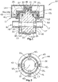
- FIG. 1 shows a schematic side view in section of a magnetic rotary slide fluid valve 10.
- the rotary slide fluid valve 10 comprises a valve housing 11 with a cylindrical housing pot 12, a bell-shaped housing cover 13 and with an actuator housing 14 placed on the housing cover 13.
- the housing pot 12 and the housing cover 13 are above the entire
- the periphery is connected to one another in a fluid-tight manner, preferably by laser welding, and form a valve chamber 15.
- the valve chamber 15 has an inlet 16 with an inlet connector 16 'and an outlet 17 with an outlet connector 17'. Furthermore, a first central valve body bearing point 19 is formed in the housing pot bottom 18 and a second central valve body bearing point 20 is formed in the housing cover 13.
- a cylindrical valve body 25 is arranged in the valve chamber 15. At the axial end of the valve body 25 directed towards the housing pot base 18, a hemispherical bearing recess 26 is formed. A bearing pin 27 is formed on the axial end of the valve body 25 directed towards the housing cover 13. The hemispherical bearing formation 26 protrudes into the valve body bearing point 19 and the bearing pin 27 protrudes into the valve body bearing point 20. In this way, the valve body 25 is rotatably supported in the valve chamber 15 about the axis of rotation 32.
- a diametrically permanently magnetized rod-shaped sensor magnet 33 is embedded in the bearing journal 27 in such a way that the cylinder axis of the sensor magnet 33 lies on the axis of rotation 32.
- the valve body 25 has, at the axial height of the inlet connection 16 ′ and the outlet connection 17 ′, a passage 28 running in the radial direction, via which the inlet 16 and the outlet 17 can be fluidically connected to one another.
- a schematically illustrated sealing element 29, 30 surrounding the inlet connector 16 'and the outlet connector 17' is arranged, which sealing element rests against an outer circumferential surface 31 of the valve body 25.
- output rotor permanent magnets 35 1 -35 4 are attached on the outer circumferential surface 31, evenly distributed over the circumference.
- the output rotor permanent magnets 35 1 -35 4 are arranged in such a way that they form an annular output rotor 36 which is alternately magnetized on the radial outer side along the circumference and which is rotatable about the axis of rotation 32.
- a bell-shaped drive part 40 is mounted on the housing cover 13 so as to be rotatable relative to the axis of rotation 32 and is fixed in the axial direction by a centrally arranged locking washer 41.
- a magnetic field sensor 45 which detects the magnetic field generated by the sensor magnet 33 in order to determine the angular position of the valve body 25, is embedded in a central position in the locking washer 41.
- each cuboid diametrically magnetized drive rotor permanent magnets 42 1 -42 4 are embedded evenly distributed over the circumference.
- the drive rotor permanent magnets 42 1 -42 4 are arranged in such a way that they form an annular drive rotor 43 which is alternately magnetized on the radially inner side along the circumference and which is rotatable about the axis of rotation 32.
- the drive rotor 43 and the output rotor 36 are coupled to one another via the magnetic fields generated by the drive rotor permanent magnets 42 1 -42 4 and by the output rotor permanent magnets 35 1 -35 4 and form as in FIG Figure 2 shown schematically a Contactless magnetic coupling 44.
- the two coupling elements i.e. the drive rotor 43 integrated in the drive part 40 with the drive rotor permanent magnets 42 1 -42 4 and the output rotor 36 attached to the valve body 25 with the output rotor permanent magnets 35 1 -35 4 are here through the housing cover 13 separated from each other in a fluid-tight manner.
- An actuator unit 50 with a valve drive 51 and with a self-locking gear 52 is also arranged in the actuator housing 14.
- the Figure 3 shows schematically an embodiment of the actuator unit 50 according to the invention.
- the valve drive 51 is formed by an electric motor 51 'which, with the aid of the self-locking gear 52 and the magnetic coupling 44, enables the valve body 25 to be rotated easily in both directions of rotation.
- the self-locking gear 52 is multi-stage and comprises a spur gear stage 53 with the spur gears 54, 55, a worm gear stage 56 with a worm 57 and a worm gear 58, which is integrated in the drive part 40, and includes two shafts 59, 60.
- a rotation of the first shaft 59 driven by the valve drive 51 about the axis of rotation 61 generates a rotation of the second shaft 59 about the axis of rotation 62 via the spur gear stage 53.
- the rotation of the shaft 59 in turn generates a rotation of the worm wheel 58 about the axis of rotation 32 via the worm 57 Since the worm wheel 58 is integrated into the drive part 40, this corresponds to a rotation of the drive part 40 about the axis of rotation 32.
- the Figure 4 shows two alternative arrangements according to the invention of the drive rotor permanent magnets 42 1 -42 4 within the drive part 40.
- the drive rotor permanent magnets 70 arranged offset from the output rotor permanent magnets 35 in the axial direction. This results in an axial component of the magnetic force acting between the drive rotor permanent magnets 70 and the driven rotor permanent magnets 35, as a result of which the valve body 25 with its bearing journal 27 is drawn into the valve body bearing point 20 in the axial direction. As a result, the axial movement play of the valve body 25 in the valve chamber 15 can be reduced.
- the drive rotor permanent magnets 71 When running after the Figure 4b the drive rotor permanent magnets 71 are tilted relative to the output rotor permanent magnets 35 so that the mutually facing magnetic surfaces of the drive rotor permanent magnets 71 and the output rotor permanent magnets 35 have an angle ⁇ between 5 ° and 45 ° to one another.
- the tilted arrangement of the drive rotor permanent magnets 71 also generates a magnetic force in the axial direction on the valve body 25, as a result of which the axial play of the valve body 25 in the valve chamber 15 can be reduced.
- the Figure 5 shows alternative versions of the drive rotor 80, 82 and the output rotor 84.
- the drive rotor 80 is designed as a magnet ring 81 which is permanently magnetized alternately along the circumference.
- the driven rotor 84 is also designed as a magnet ring 85 that is permanently magnetized alternately along the circumference.
- the drive rotor 82 has twelve drive rotor permanent magnets 83 1 -83 12 evenly distributed over the circumference of the drive rotor 82.
- the output rotor 36 and thus also the valve body 25 can be preloaded in the tangential direction. This allows the movement play of the valve body 25 to be reduced in the tangential direction.
- the magnetic rotary slide valve according to the invention is not limited to the rotary slide valve described.
- the number of inlet nozzles, outlet nozzles and passage channels can differ from the exemplary embodiment described.
- the multi-stage self-locking gearing also allows the components of the actuator unit, i.e. the valve drive and the gearing, to be arranged in a space-optimized manner, whereby the space required can also be reduced.
Landscapes
- Engineering & Computer Science (AREA)
- General Engineering & Computer Science (AREA)
- Mechanical Engineering (AREA)
- Electrically Driven Valve-Operating Means (AREA)
Claims (15)
- Vanne de fluide à tiroir rotatif magnétique (10) avec un carter de vanne (11) comportant un pot de carter (12) cylindrique et un couvercle de carter (13) en forme de cloche comprenant une chambre de vanne (15),un corps de vanne (25) supporté dans la chambre de vanne (15) de manière rotative autour d'un axe de rotation (32),un couplage magnétique (44) avec un rotor de sortie (36) monté sur le corps de vanne (25) et comprenant au moins un aimant permanent du rotor de sortie (351-354) et un rotor d'entrainement (43) disposé hors de la chambre de vanne (15) et comprenant au moins un aimant permanent du rotor d'entrainement (421-424), ledit rotor d'entrainement (43) et ledit rotor de sortie (36) étant couplé par des forces magnétiques et étant séparé l'un de l'autre de manière étanche à fluide pour le couplage du corps de vanne (25) avec un entrainement de vanne (51), ledit rotor de sortie (36) étant magnétisé en alternance sur l'extérieur radial le long de la circonférence,ledit rotor d'entrainement (43) étant magnétisé en alternance sur l'intérieur radial le long de la circonférence, etledit rotor d'entrainement (43) est en forme annulaire et entoure le rotor de sortie (36) au moins partiellement dans la direction axiale,caractérisée en ce quela vanne de fluide à tiroir rotatif magnétique (10) comprend un capteur de champ magnétique (45) pour la détection de la position angulaire du corps de vanne (25), le capteur étant disposé hors de la chambre de vanne (15) dans un carter d'actionneur (14) placé sur le couvercle de carter (13), un aimant de capteur (33) magnétisé en permanence étant monté sur ledit corps de vanne (25) dans une broche de support (27) formée dans une extrémité axiale du corps de vanne (25) tournée vers le couvercle de carter (13) et ledit capteur de champ magnétique (45) détecte le champ magnétique généré par l'aimant de capteur (33).
- Vanne de fluide à tiroir rotatif magnétique (10) selon la revendication 1, caractérisée en ce que le rotor d'entrainement (43) est intégré dans un élément d'entrainement (40) en forme de cloche entourant ledit rotor de sortie (36) au moins partiellement dans la direction axiale.
- Vanne de fluide à tiroir rotatif magnétique (10) selon la revendication 1 ou 2, caractérisée en ce que le pot de carter (12) cylindrique du carter de vanne (11) comprend une première position de support du corps de vanne (10) centrale axiale, et le couvercle de carter (13) renfermant le pot de carter (12) de manière étanche à fluide comprend une deuxième position de support du corps de vanne (20) centrale axiale.
- Vanne de fluide à tiroir rotatif magnétique (10) selon la revendication 3, caractérisée en ce que l'entrainement (51) apte à être couplé avec le corps de vanne (25) peut être disposé dans le carter d'actionneur (14).
- Vanne de fluide à tiroir rotatif magnétique (10) selon la revendication 3 ou 4, caractérisée en ce que dans le carter d'actionneur (14), le rotor d'entrainement (43) est supporté de manière glissante sur le couvercle de carter (13).
- Vanne de fluide à tiroir rotatif magnétique (10) selon l'une quelconque des revendications précédentes, caractérisée en ce que le rotor d'entrainement (43) peut être couplé avec l'entrainement de vanne (51) par l'intermédiaire d'un engrenage autobloquant (57).
- Vanne de fluide à tiroir rotatif magnétique (10) selon la revendication 6, caractérisée en ce que l'engrenage autobloquant (52) comprend un étage d'engrenage droit (53) et un étage d'engrenage à vis sans fin (56).
- Vanne de fluide à tiroir rotatif magnétique (10) selon la revendication 7, caractérisée en ce que le rotor d'entrainement (43) est intégré dans la vis sans fin (58) de l'étage d'engrenage à vis sans fin (56).
- Vanne de fluide à tiroir rotatif magnétique (10) selon l'une quelconque des revendications précédentes, caractérisée en ce que le rotor d'entrainement (43) ou le rotor de sortie (36) comprend des segments d'aimant (421-424) magnétisés en permanence en alternance le long de la circonférence.
- Vanne de fluide à tiroir rotatif magnétique (10) selon l'une quelconque des revendications précédentes, caractérisée en ce que le rotor d'entrainement (80) ou le rotor de sortie (84) comprend un anneau d'aimant (81, 85) magnétisé en permanence en alternance le long de la circonférence.
- Vanne de fluide à tiroir rotatif magnétique (10) selon l'une quelconque des revendications précédentes, caractérisée en ce que ledit au moins un aimant permanent du rotor d'entrainement (70) et ledit au moins un aimant permanent du rotor de sortie (351-354) sont disposés à des niveaux axiaux différents.
- Vanne de fluide à tiroir rotatif magnétique (10) selon l'une quelconque des revendications précédentes, caractérisée en ce que ledit au moins un aimant permanent du rotor d'entrainement (71) et ledit au moins un aimant permanent du rotor de sortie (351-354) sont disposés de sorte que les surfaces d'aimant dudit au moins un aimant permanent du rotor d'entrainement (71) et dudit au moins un aimant permanent du rotor de sortie (351-354) tournées l'une vers l'autre présentent un angle α entre 5° et 45° l'une par rapport à l'autre.
- Vanne de fluide à tiroir rotatif magnétique (10) selon l'une quelconque des revendications précédentes, caractérisée en ce que le rotor d'entrainement (80) et le rotor de sortie (84) comprennent différents nombres de pôles magnétiques.
- Vanne de fluide à tiroir rotatif magnétique (10) selon l'une quelconque des revendications précédentes, caractérisée en ce que, dans la chambre de vanne (15), le corps de vanne (25) est supporté axialement par la broche de support (27).
- Vanne de fluide à tiroir rotatif magnétique (10) selon l'une quelconque des revendications précédentes, caractérisée en ce que l'entrainement de vanne (51) est un moteur électrique (51').
Applications Claiming Priority (1)
| Application Number | Priority Date | Filing Date | Title |
|---|---|---|---|
| DE102017128127.4A DE102017128127B4 (de) | 2017-11-28 | 2017-11-28 | Magnetisches Drehschieberfluidventil |
Publications (2)
| Publication Number | Publication Date |
|---|---|
| EP3489559A1 EP3489559A1 (fr) | 2019-05-29 |
| EP3489559B1 true EP3489559B1 (fr) | 2021-12-01 |
Family
ID=64082903
Family Applications (1)
| Application Number | Title | Priority Date | Filing Date |
|---|---|---|---|
| EP18203017.1A Active EP3489559B1 (fr) | 2017-11-28 | 2018-10-29 | Soupape à fluide rotative magnétique |
Country Status (2)
| Country | Link |
|---|---|
| EP (1) | EP3489559B1 (fr) |
| DE (1) | DE102017128127B4 (fr) |
Families Citing this family (3)
| Publication number | Priority date | Publication date | Assignee | Title |
|---|---|---|---|---|
| US12072040B2 (en) * | 2019-10-10 | 2024-08-27 | Avk Holding A/S | Method for determining a position of a blocking element in a valve, a sensor system and use of a sensor system |
| DE102021201319A1 (de) * | 2021-02-12 | 2022-08-18 | Robert Bosch Gesellschaft mit beschränkter Haftung | Stellvorrichtung, insbesondere für den Einsatz unter Wasser, mit einer Magnetkupplung |
| DE102022111976A1 (de) | 2022-05-12 | 2023-11-16 | Woco Industrietechnik Gmbh | Stellventil und Leitungssystem |
Citations (2)
| Publication number | Priority date | Publication date | Assignee | Title |
|---|---|---|---|---|
| US3134404A (en) * | 1961-02-27 | 1964-05-26 | William B Jaspert | Electro-magnetically operated floating armature valves |
| WO2003100950A1 (fr) * | 2002-05-25 | 2003-12-04 | Robert Bosch Gmbh | Servomoteur electrique |
Family Cites Families (13)
| Publication number | Priority date | Publication date | Assignee | Title |
|---|---|---|---|---|
| US3347262A (en) * | 1965-09-22 | 1967-10-17 | Mark Associates Inc | Magnet actuated sealed valve |
| US4327892A (en) * | 1980-09-08 | 1982-05-04 | Autoclave Engineers, Inc. | Normally magnetically actuated valve with novel nonmagnetic override |
| DE8715977U1 (de) * | 1987-12-03 | 1988-01-21 | Franz Klaus Union Armaturen, Pumpen Gmbh & Co, 4630 Bochum | Gas- und flüssigkeitsdichter Antrieb für ein Absperrorgan |
| US5083744A (en) * | 1991-03-08 | 1992-01-28 | Morotta Scientific Controls, Inc. | Motor-operated valve |
| DE102005041973A1 (de) * | 2005-09-03 | 2007-09-13 | Werth, Vladimir, Dipl.-Ing. | Einstellbares-Permanentmagnetkupplung |
| FR2947606B1 (fr) | 2009-07-03 | 2015-02-20 | Inst Francais Du Petrole | Distributeur hydraulique a trois voies et commande a entrainement magnetique |
| DE102009033160A1 (de) * | 2009-07-13 | 2011-01-27 | Porep Gmbh | Ventil |
| IT1397055B1 (it) * | 2009-12-29 | 2012-12-28 | Soldo S R L Socio Unico | Dispositivo indicatore di posizione di una valvola rotativa e metodo per indicare la posizione di una valvola rotativa |
| JP5858220B2 (ja) * | 2011-10-05 | 2016-02-10 | 日本電産株式会社 | モータ |
| US9377121B2 (en) * | 2011-12-03 | 2016-06-28 | Big Horn Valve, Inc. | Leak-free rotary valve with internal worm gear |
| CA2855315C (fr) * | 2013-06-28 | 2021-08-10 | DePuy Synthes Products, LLC | Methode et outil de dispositif implante |
| DE102014224151A1 (de) * | 2014-11-26 | 2016-06-02 | Mahle International Gmbh | Vorrichtung zur berührungslosen Übertragung von Drehbewegungen |
| US9797521B1 (en) * | 2016-08-09 | 2017-10-24 | Edward P Davis | Rotary magnetic coupling actuated valve with external magnets and internal magnetic flux path |
-
2017
- 2017-11-28 DE DE102017128127.4A patent/DE102017128127B4/de active Active
-
2018
- 2018-10-29 EP EP18203017.1A patent/EP3489559B1/fr active Active
Patent Citations (2)
| Publication number | Priority date | Publication date | Assignee | Title |
|---|---|---|---|---|
| US3134404A (en) * | 1961-02-27 | 1964-05-26 | William B Jaspert | Electro-magnetically operated floating armature valves |
| WO2003100950A1 (fr) * | 2002-05-25 | 2003-12-04 | Robert Bosch Gmbh | Servomoteur electrique |
Also Published As
| Publication number | Publication date |
|---|---|
| EP3489559A1 (fr) | 2019-05-29 |
| DE102017128127A1 (de) | 2019-05-29 |
| DE102017128127B4 (de) | 2023-05-04 |
Similar Documents
| Publication | Publication Date | Title |
|---|---|---|
| EP3489559B1 (fr) | Soupape à fluide rotative magnétique | |
| DE2312486C2 (de) | Elektromagnetisch betätigbare Schlingfederkupplung | |
| EP0981696B1 (fr) | Transmission a roue dentee excentrique | |
| EP2473690B2 (fr) | Dispositif de verrouillage | |
| EP3824249B1 (fr) | Système de mesure d'angle de rotation | |
| DE202021106468U1 (de) | Fluidvorrichtung | |
| DE102019134949B4 (de) | Ventilvorrichtung | |
| DE202014103691U1 (de) | Motorisierte Servorrichtung | |
| DE102007020525A1 (de) | Nockenwellenversteller für eine Brennkraftmaschine mit integriertem Ventilschieber | |
| EP3913267B1 (fr) | Dispositif d'entraînement permettant d'actionner une soupape à boisseau | |
| EP1529144A1 (fr) | Dispositif de verrouillage destine a des vehicules, notamment a des avions | |
| DE102022100369B3 (de) | Elektromotor zum Antrieb einer Fahrzeugklappe, Verwendung und Verfahren zur Herstellung des Elektromotors | |
| EP2818725A1 (fr) | Pompe centrifuge avec roue à aubes déplaçable axialement et obturable | |
| DE102012207748A1 (de) | Schwenkeinrichtung für eine Schiffspropellergondel | |
| DE112017006417B4 (de) | Untersetzungsgetriebe, fahrzeugsitz | |
| WO2010031683A2 (fr) | Pompe à vide | |
| WO2020074605A1 (fr) | Actionneur rotatif magnétique et unité de commande de véhicule automobile | |
| EP3953619B1 (fr) | Soupape à tiroir rotatif pour un véhicule automobile | |
| DE102022118426B4 (de) | Planetengetriebe | |
| EP0866543A2 (fr) | Entraínement de positionneur | |
| EP4194720A1 (fr) | Unité de verrouillage | |
| EP1563587B1 (fr) | Dispositif d'entrainement pour dispositifs de reglage de vehicules automobiles | |
| DE102020210407A1 (de) | Rotationsmaschine mit Positionssensor | |
| EP1477714B1 (fr) | Actionneur pour soupape | |
| WO2021223797A1 (fr) | Dispositif de commutation |
Legal Events
| Date | Code | Title | Description |
|---|---|---|---|
| PUAI | Public reference made under article 153(3) epc to a published international application that has entered the european phase |
Free format text: ORIGINAL CODE: 0009012 |
|
| STAA | Information on the status of an ep patent application or granted ep patent |
Free format text: STATUS: THE APPLICATION HAS BEEN PUBLISHED |
|
| AK | Designated contracting states |
Kind code of ref document: A1 Designated state(s): AL AT BE BG CH CY CZ DE DK EE ES FI FR GB GR HR HU IE IS IT LI LT LU LV MC MK MT NL NO PL PT RO RS SE SI SK SM TR |
|
| AX | Request for extension of the european patent |
Extension state: BA ME |
|
| STAA | Information on the status of an ep patent application or granted ep patent |
Free format text: STATUS: REQUEST FOR EXAMINATION WAS MADE |
|
| 17P | Request for examination filed |
Effective date: 20191129 |
|
| RBV | Designated contracting states (corrected) |
Designated state(s): AL AT BE BG CH CY CZ DE DK EE ES FI FR GB GR HR HU IE IS IT LI LT LU LV MC MK MT NL NO PL PT RO RS SE SI SK SM TR |
|
| STAA | Information on the status of an ep patent application or granted ep patent |
Free format text: STATUS: EXAMINATION IS IN PROGRESS |
|
| 17Q | First examination report despatched |
Effective date: 20200408 |
|
| GRAJ | Information related to disapproval of communication of intention to grant by the applicant or resumption of examination proceedings by the epo deleted |
Free format text: ORIGINAL CODE: EPIDOSDIGR1 |
|
| STAA | Information on the status of an ep patent application or granted ep patent |
Free format text: STATUS: GRANT OF PATENT IS INTENDED |
|
| GRAP | Despatch of communication of intention to grant a patent |
Free format text: ORIGINAL CODE: EPIDOSNIGR1 |
|
| INTG | Intention to grant announced |
Effective date: 20210614 |
|
| GRAS | Grant fee paid |
Free format text: ORIGINAL CODE: EPIDOSNIGR3 |
|
| GRAA | (expected) grant |
Free format text: ORIGINAL CODE: 0009210 |
|
| STAA | Information on the status of an ep patent application or granted ep patent |
Free format text: STATUS: THE PATENT HAS BEEN GRANTED |
|
| AK | Designated contracting states |
Kind code of ref document: B1 Designated state(s): AL AT BE BG CH CY CZ DE DK EE ES FI FR GB GR HR HU IE IS IT LI LT LU LV MC MK MT NL NO PL PT RO RS SE SI SK SM TR |
|
| REG | Reference to a national code |
Ref country code: GB Ref legal event code: FG4D Free format text: NOT ENGLISH |
|
| REG | Reference to a national code |
Ref country code: AT Ref legal event code: REF Ref document number: 1452065 Country of ref document: AT Kind code of ref document: T Effective date: 20211215 Ref country code: CH Ref legal event code: EP |
|
| REG | Reference to a national code |
Ref country code: IE Ref legal event code: FG4D Free format text: LANGUAGE OF EP DOCUMENT: GERMAN |
|
| REG | Reference to a national code |
Ref country code: DE Ref legal event code: R096 Ref document number: 502018008028 Country of ref document: DE |
|
| REG | Reference to a national code |
Ref country code: LT Ref legal event code: MG9D |
|
| REG | Reference to a national code |
Ref country code: NL Ref legal event code: MP Effective date: 20211201 |
|
| PG25 | Lapsed in a contracting state [announced via postgrant information from national office to epo] |
Ref country code: RS Free format text: LAPSE BECAUSE OF FAILURE TO SUBMIT A TRANSLATION OF THE DESCRIPTION OR TO PAY THE FEE WITHIN THE PRESCRIBED TIME-LIMIT Effective date: 20211201 Ref country code: LT Free format text: LAPSE BECAUSE OF FAILURE TO SUBMIT A TRANSLATION OF THE DESCRIPTION OR TO PAY THE FEE WITHIN THE PRESCRIBED TIME-LIMIT Effective date: 20211201 Ref country code: FI Free format text: LAPSE BECAUSE OF FAILURE TO SUBMIT A TRANSLATION OF THE DESCRIPTION OR TO PAY THE FEE WITHIN THE PRESCRIBED TIME-LIMIT Effective date: 20211201 Ref country code: BG Free format text: LAPSE BECAUSE OF FAILURE TO SUBMIT A TRANSLATION OF THE DESCRIPTION OR TO PAY THE FEE WITHIN THE PRESCRIBED TIME-LIMIT Effective date: 20220301 |
|
| PG25 | Lapsed in a contracting state [announced via postgrant information from national office to epo] |
Ref country code: SE Free format text: LAPSE BECAUSE OF FAILURE TO SUBMIT A TRANSLATION OF THE DESCRIPTION OR TO PAY THE FEE WITHIN THE PRESCRIBED TIME-LIMIT Effective date: 20211201 Ref country code: PL Free format text: LAPSE BECAUSE OF FAILURE TO SUBMIT A TRANSLATION OF THE DESCRIPTION OR TO PAY THE FEE WITHIN THE PRESCRIBED TIME-LIMIT Effective date: 20211201 Ref country code: NO Free format text: LAPSE BECAUSE OF FAILURE TO SUBMIT A TRANSLATION OF THE DESCRIPTION OR TO PAY THE FEE WITHIN THE PRESCRIBED TIME-LIMIT Effective date: 20220301 Ref country code: LV Free format text: LAPSE BECAUSE OF FAILURE TO SUBMIT A TRANSLATION OF THE DESCRIPTION OR TO PAY THE FEE WITHIN THE PRESCRIBED TIME-LIMIT Effective date: 20211201 Ref country code: HR Free format text: LAPSE BECAUSE OF FAILURE TO SUBMIT A TRANSLATION OF THE DESCRIPTION OR TO PAY THE FEE WITHIN THE PRESCRIBED TIME-LIMIT Effective date: 20211201 Ref country code: GR Free format text: LAPSE BECAUSE OF FAILURE TO SUBMIT A TRANSLATION OF THE DESCRIPTION OR TO PAY THE FEE WITHIN THE PRESCRIBED TIME-LIMIT Effective date: 20220302 Ref country code: ES Free format text: LAPSE BECAUSE OF FAILURE TO SUBMIT A TRANSLATION OF THE DESCRIPTION OR TO PAY THE FEE WITHIN THE PRESCRIBED TIME-LIMIT Effective date: 20211201 |
|
| PG25 | Lapsed in a contracting state [announced via postgrant information from national office to epo] |
Ref country code: NL Free format text: LAPSE BECAUSE OF FAILURE TO SUBMIT A TRANSLATION OF THE DESCRIPTION OR TO PAY THE FEE WITHIN THE PRESCRIBED TIME-LIMIT Effective date: 20211201 |
|
| PG25 | Lapsed in a contracting state [announced via postgrant information from national office to epo] |
Ref country code: SM Free format text: LAPSE BECAUSE OF FAILURE TO SUBMIT A TRANSLATION OF THE DESCRIPTION OR TO PAY THE FEE WITHIN THE PRESCRIBED TIME-LIMIT Effective date: 20211201 Ref country code: SK Free format text: LAPSE BECAUSE OF FAILURE TO SUBMIT A TRANSLATION OF THE DESCRIPTION OR TO PAY THE FEE WITHIN THE PRESCRIBED TIME-LIMIT Effective date: 20211201 Ref country code: RO Free format text: LAPSE BECAUSE OF FAILURE TO SUBMIT A TRANSLATION OF THE DESCRIPTION OR TO PAY THE FEE WITHIN THE PRESCRIBED TIME-LIMIT Effective date: 20211201 Ref country code: PT Free format text: LAPSE BECAUSE OF FAILURE TO SUBMIT A TRANSLATION OF THE DESCRIPTION OR TO PAY THE FEE WITHIN THE PRESCRIBED TIME-LIMIT Effective date: 20220401 Ref country code: EE Free format text: LAPSE BECAUSE OF FAILURE TO SUBMIT A TRANSLATION OF THE DESCRIPTION OR TO PAY THE FEE WITHIN THE PRESCRIBED TIME-LIMIT Effective date: 20211201 Ref country code: CZ Free format text: LAPSE BECAUSE OF FAILURE TO SUBMIT A TRANSLATION OF THE DESCRIPTION OR TO PAY THE FEE WITHIN THE PRESCRIBED TIME-LIMIT Effective date: 20211201 |
|
| REG | Reference to a national code |
Ref country code: DE Ref legal event code: R097 Ref document number: 502018008028 Country of ref document: DE |
|
| PG25 | Lapsed in a contracting state [announced via postgrant information from national office to epo] |
Ref country code: IS Free format text: LAPSE BECAUSE OF FAILURE TO SUBMIT A TRANSLATION OF THE DESCRIPTION OR TO PAY THE FEE WITHIN THE PRESCRIBED TIME-LIMIT Effective date: 20220401 |
|
| PLBE | No opposition filed within time limit |
Free format text: ORIGINAL CODE: 0009261 |
|
| STAA | Information on the status of an ep patent application or granted ep patent |
Free format text: STATUS: NO OPPOSITION FILED WITHIN TIME LIMIT |
|
| PG25 | Lapsed in a contracting state [announced via postgrant information from national office to epo] |
Ref country code: DK Free format text: LAPSE BECAUSE OF FAILURE TO SUBMIT A TRANSLATION OF THE DESCRIPTION OR TO PAY THE FEE WITHIN THE PRESCRIBED TIME-LIMIT Effective date: 20211201 Ref country code: AL Free format text: LAPSE BECAUSE OF FAILURE TO SUBMIT A TRANSLATION OF THE DESCRIPTION OR TO PAY THE FEE WITHIN THE PRESCRIBED TIME-LIMIT Effective date: 20211201 |
|
| 26N | No opposition filed |
Effective date: 20220902 |
|
| PG25 | Lapsed in a contracting state [announced via postgrant information from national office to epo] |
Ref country code: SI Free format text: LAPSE BECAUSE OF FAILURE TO SUBMIT A TRANSLATION OF THE DESCRIPTION OR TO PAY THE FEE WITHIN THE PRESCRIBED TIME-LIMIT Effective date: 20211201 |
|
| PG25 | Lapsed in a contracting state [announced via postgrant information from national office to epo] |
Ref country code: MC Free format text: LAPSE BECAUSE OF FAILURE TO SUBMIT A TRANSLATION OF THE DESCRIPTION OR TO PAY THE FEE WITHIN THE PRESCRIBED TIME-LIMIT Effective date: 20211201 Ref country code: IT Free format text: LAPSE BECAUSE OF FAILURE TO SUBMIT A TRANSLATION OF THE DESCRIPTION OR TO PAY THE FEE WITHIN THE PRESCRIBED TIME-LIMIT Effective date: 20211201 |
|
| REG | Reference to a national code |
Ref country code: CH Ref legal event code: PL |
|
| REG | Reference to a national code |
Ref country code: BE Ref legal event code: MM Effective date: 20221031 |
|
| GBPC | Gb: european patent ceased through non-payment of renewal fee |
Effective date: 20221029 |
|
| PG25 | Lapsed in a contracting state [announced via postgrant information from national office to epo] |
Ref country code: LU Free format text: LAPSE BECAUSE OF NON-PAYMENT OF DUE FEES Effective date: 20221029 |
|
| PG25 | Lapsed in a contracting state [announced via postgrant information from national office to epo] |
Ref country code: LI Free format text: LAPSE BECAUSE OF NON-PAYMENT OF DUE FEES Effective date: 20221031 Ref country code: CH Free format text: LAPSE BECAUSE OF NON-PAYMENT OF DUE FEES Effective date: 20221031 |
|
| PG25 | Lapsed in a contracting state [announced via postgrant information from national office to epo] |
Ref country code: BE Free format text: LAPSE BECAUSE OF NON-PAYMENT OF DUE FEES Effective date: 20221031 |
|
| PG25 | Lapsed in a contracting state [announced via postgrant information from national office to epo] |
Ref country code: IE Free format text: LAPSE BECAUSE OF NON-PAYMENT OF DUE FEES Effective date: 20221029 Ref country code: GB Free format text: LAPSE BECAUSE OF NON-PAYMENT OF DUE FEES Effective date: 20221029 |
|
| PG25 | Lapsed in a contracting state [announced via postgrant information from national office to epo] |
Ref country code: HU Free format text: LAPSE BECAUSE OF FAILURE TO SUBMIT A TRANSLATION OF THE DESCRIPTION OR TO PAY THE FEE WITHIN THE PRESCRIBED TIME-LIMIT; INVALID AB INITIO Effective date: 20181029 |
|
| PG25 | Lapsed in a contracting state [announced via postgrant information from national office to epo] |
Ref country code: CY Free format text: LAPSE BECAUSE OF FAILURE TO SUBMIT A TRANSLATION OF THE DESCRIPTION OR TO PAY THE FEE WITHIN THE PRESCRIBED TIME-LIMIT Effective date: 20211201 |
|
| PG25 | Lapsed in a contracting state [announced via postgrant information from national office to epo] |
Ref country code: MK Free format text: LAPSE BECAUSE OF FAILURE TO SUBMIT A TRANSLATION OF THE DESCRIPTION OR TO PAY THE FEE WITHIN THE PRESCRIBED TIME-LIMIT Effective date: 20211201 |
|
| PG25 | Lapsed in a contracting state [announced via postgrant information from national office to epo] |
Ref country code: TR Free format text: LAPSE BECAUSE OF FAILURE TO SUBMIT A TRANSLATION OF THE DESCRIPTION OR TO PAY THE FEE WITHIN THE PRESCRIBED TIME-LIMIT Effective date: 20211201 |
|
| PG25 | Lapsed in a contracting state [announced via postgrant information from national office to epo] |
Ref country code: MT Free format text: LAPSE BECAUSE OF FAILURE TO SUBMIT A TRANSLATION OF THE DESCRIPTION OR TO PAY THE FEE WITHIN THE PRESCRIBED TIME-LIMIT Effective date: 20211201 |
|
| REG | Reference to a national code |
Ref country code: AT Ref legal event code: MM01 Ref document number: 1452065 Country of ref document: AT Kind code of ref document: T Effective date: 20231029 |
|
| PG25 | Lapsed in a contracting state [announced via postgrant information from national office to epo] |
Ref country code: AT Free format text: LAPSE BECAUSE OF NON-PAYMENT OF DUE FEES Effective date: 20231029 |
|
| PG25 | Lapsed in a contracting state [announced via postgrant information from national office to epo] |
Ref country code: AT Free format text: LAPSE BECAUSE OF NON-PAYMENT OF DUE FEES Effective date: 20231029 |
|
| PGFP | Annual fee paid to national office [announced via postgrant information from national office to epo] |
Ref country code: DE Payment date: 20251021 Year of fee payment: 8 |
|
| PGFP | Annual fee paid to national office [announced via postgrant information from national office to epo] |
Ref country code: FR Payment date: 20251030 Year of fee payment: 8 |
|
| REG | Reference to a national code |
Ref country code: DE Ref legal event code: R082 Ref document number: 502018008028 Country of ref document: DE |
|
| PGFP | Annual fee paid to national office [announced via postgrant information from national office to epo] |
Ref country code: AT Payment date: 20260410 Year of fee payment: 5 |