EP3489573A1 - Taschenlampe - Google Patents
Taschenlampe Download PDFInfo
- Publication number
- EP3489573A1 EP3489573A1 EP18204775.3A EP18204775A EP3489573A1 EP 3489573 A1 EP3489573 A1 EP 3489573A1 EP 18204775 A EP18204775 A EP 18204775A EP 3489573 A1 EP3489573 A1 EP 3489573A1
- Authority
- EP
- European Patent Office
- Prior art keywords
- light source
- actuating element
- flashlight according
- lever
- slide
- Prior art date
- Legal status (The legal status is an assumption and is not a legal conclusion. Google has not performed a legal analysis and makes no representation as to the accuracy of the status listed.)
- Granted
Links
Images




Classifications
-
- F—MECHANICAL ENGINEERING; LIGHTING; HEATING; WEAPONS; BLASTING
- F21—LIGHTING
- F21L—LIGHTING DEVICES OR SYSTEMS THEREOF, BEING PORTABLE OR SPECIALLY ADAPTED FOR TRANSPORTATION
- F21L4/00—Electric lighting devices with self-contained electric batteries or cells
- F21L4/04—Electric lighting devices with self-contained electric batteries or cells characterised by the provision of a light source housing portion adjustably fixed to the remainder of the device
- F21L4/045—Pocket lamps
-
- F—MECHANICAL ENGINEERING; LIGHTING; HEATING; WEAPONS; BLASTING
- F21—LIGHTING
- F21V—FUNCTIONAL FEATURES OR DETAILS OF LIGHTING DEVICES OR SYSTEMS THEREOF; STRUCTURAL COMBINATIONS OF LIGHTING DEVICES WITH OTHER ARTICLES, NOT OTHERWISE PROVIDED FOR
- F21V14/00—Controlling the distribution of the light emitted by adjustment of elements
- F21V14/04—Controlling the distribution of the light emitted by adjustment of elements by movement of reflectors
- F21V14/045—Controlling the distribution of the light emitted by adjustment of elements by movement of reflectors in portable lighting devices
-
- F—MECHANICAL ENGINEERING; LIGHTING; HEATING; WEAPONS; BLASTING
- F21—LIGHTING
- F21V—FUNCTIONAL FEATURES OR DETAILS OF LIGHTING DEVICES OR SYSTEMS THEREOF; STRUCTURAL COMBINATIONS OF LIGHTING DEVICES WITH OTHER ARTICLES, NOT OTHERWISE PROVIDED FOR
- F21V14/00—Controlling the distribution of the light emitted by adjustment of elements
- F21V14/06—Controlling the distribution of the light emitted by adjustment of elements by movement of refractors
- F21V14/065—Controlling the distribution of the light emitted by adjustment of elements by movement of refractors in portable lighting devices
-
- F—MECHANICAL ENGINEERING; LIGHTING; HEATING; WEAPONS; BLASTING
- F21—LIGHTING
- F21V—FUNCTIONAL FEATURES OR DETAILS OF LIGHTING DEVICES OR SYSTEMS THEREOF; STRUCTURAL COMBINATIONS OF LIGHTING DEVICES WITH OTHER ARTICLES, NOT OTHERWISE PROVIDED FOR
- F21V23/00—Arrangement of electric circuit elements in or on lighting devices
- F21V23/04—Arrangement of electric circuit elements in or on lighting devices the elements being switches
- F21V23/0414—Arrangement of electric circuit elements in or on lighting devices the elements being switches specially adapted to be used with portable lighting devices
- F21V23/0428—Arrangement of electric circuit elements in or on lighting devices the elements being switches specially adapted to be used with portable lighting devices the switch being part of, or disposed on the lamp head portion thereof
-
- F—MECHANICAL ENGINEERING; LIGHTING; HEATING; WEAPONS; BLASTING
- F21—LIGHTING
- F21V—FUNCTIONAL FEATURES OR DETAILS OF LIGHTING DEVICES OR SYSTEMS THEREOF; STRUCTURAL COMBINATIONS OF LIGHTING DEVICES WITH OTHER ARTICLES, NOT OTHERWISE PROVIDED FOR
- F21V31/00—Gas-tight or water-tight arrangements
- F21V31/005—Sealing arrangements therefor
-
- F—MECHANICAL ENGINEERING; LIGHTING; HEATING; WEAPONS; BLASTING
- F21—LIGHTING
- F21Y—INDEXING SCHEME ASSOCIATED WITH SUBCLASSES F21K, F21L, F21S and F21V, RELATING TO THE FORM OR THE KIND OF THE LIGHT SOURCES OR OF THE COLOUR OF THE LIGHT EMITTED
- F21Y2115/00—Light-generating elements of semiconductor light sources
- F21Y2115/10—Light-emitting diodes [LED]
Definitions
- the invention relates to a flashlight with a lamp housing arranged in a light source and an optical attachment, which is movable for focusing the light cone emitted by the light source by means of a slider relative to the light source in the longitudinal axial direction.
- Older known flashlights had as light source an incandescent lamp, which was surrounded by a reflector body, which was closed at the front with a glass plate or a lens. By turning the conical lamp head, the lamp head was moved longitudinally axially via a slotted guide, which also allowed the cone angle of the light cone to be changed.
- the light source an LED
- the lamp head which is fixedly connected to the attachment optics, relative to the longitudinal axis axially displaceable.
- the determination of the set distance between the LED and the attachment optics should be effected in that by pivoting a clamping body is pivoted or spread in the radial direction, so that a friction or positive fixing of the lamp head is made.
- the flashlight according to claim 1 which is characterized according to the invention by a two-armed lever, with the first end of the slider is actuated and the second end protrudes as an actuator from the lamp housing.
- the lever arm equipped with the actuating element is shorter than the other lever arm connected to the slider.
- the "gear ratio" that is, the ratio of the pivoting path of the actuator to the path over which the slide by means of the preferably longer lever arm is determined solely by the ratio of the lever arms.
- short lever arms on the control side have the advantage that, unlike sliding pins, a high density can be achieved.
- the actuating element of the lever arm is designed simultaneously for actuating the pressure switch. In this way, with just a single control element, both the focusing and the switching on and off of the lamp can be obtained with one-handed or one-finger operation. In addition, the sealing of only a single actuator is less expensive.
- the arm of the two-armed lever used for switching on and off the light source is mounted longitudinally axially movable, wherein in a longitudinal axial movement via a driver a push-button for switching on and off of the light source can be actuated.
- a preferred embodiment consists in the use of an elastic ring body as the axis of rotation of the two-armed lever, wherein preferably an annular collar of the annular body engages in an annular groove of the actuating element.
- the ring body is inserted into an opening of the lamp housing shell and further preferably designed as a seal.
- the end opposite the actuating element of the two-armed lever serves to displace the slide or the attachment optics with respect to the LED.
- the lever arm engages at its end opposite the actuating element between two profile body, which are part of the slide or which are firmly connected to the slider.
- a support member mounted as a lever is used as a driver whose legs engage recesses formed in both sides of the two-armed lever, so that in a longitudinal axial movement of the two-armed lever, the slit body in the direction of the pressure switch is pivotable.
- the structure of the flashlight, in particular the displacement mechanism is simple and due to the parts used largely wear-free and correspondingsunanriz.
- Battery powered flashlights equipped with diodes are well known in the art, so the following description will be concerned essentially with the recliner mechanisms as well as the power on and off parts.
- Flashlight shown is cylindrical in shape and consists of a housing part 10, which serves as a battery compartment and a lamp head 11, in which, inter alia, the preferably designed as a LED light source and an attachment optics are arranged.
- the end face 12 of the lamp head 11 represents the Light exit opening is on the outer surface of the lamp head 11, an actuating element 13 is arranged, which is formed simultaneously as an on-off switch as well as an actuator for focusing the lamp.
- the actuator 13 is mounted in an elastic ring body 14, which also serves as a seal to prevent ingress of moisture.
- Fig. 2 and 3 show individual parts of the lamp head 11 in an exploded view and in a cross-sectional view in the assembled state.
- the essential parts of the lamp head are arranged on a board 15 LED 16 and the attachment optics 17, which may be formed for example as a Fresnel lens and by means of a slider 18 relative to the LED 16 by linear displacement of the slider 18 in the longitudinal direction of the flashlight 10, 11 is displaceable.
- the attachment optics 17 For linear displacement of the attachment optics 17 is a two-armed lever 19, at the first end of the actuator 13 is arranged and the opposite end 20 consists of a plate-shaped pin, which, as from Fig.
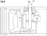
- Fig. 6 shows the displacement of the attachment optics 17 with the greatest possible distance from the LED 16 and Fig. 7 the linear displacement of the attachment optics 17 with the smallest possible distance to the LED 16.
- the linear displacement of the attachment optics within the lamp head 11 is achieved exclusively by pivoting the two-armed lever 19.
- the position of the axis of rotation is determined by the interaction of the actuating element 13 and the annular body 14.
- the actuating element 13 has on its underside an annular groove 131 in which an annular collar 141 engages.
- the elastic ring body 14 has on its outer shell an annular groove 142, in which engages an annular projection 111 of the lamp head 11.
- the annular collar 141 forms with the annular base body an integral part, which prevents penetration of moisture or dust into the lamp head, because the annular collar 141 tightly against the bottom of the groove 131 and the outer shell 132 also sealingly abuts against the ring inner wall 143.
- the two-armed lever 19 also has on both sides a recess 191, against which the legs 261 and 262 of a driver 26. By displacement of the two-armed lever 19 in its longitudinal axial direction, that is, by pressing on the head of the actuating element 13, the driver 26 is as in Fig. 5 shown pivoted and at the same time the key switch 27 is actuated, which serves for switching on and off of the LED 16.
- the driver 26 is formed as a slit body, which allows pivoting of the lever 19 along the slot between the two legs 261 and 262, so that the actuator 13 both as an on-off switch and as an actuator for the longitudinal axial displacement of the attachment optics 17 in the lamp head 11 serves.
- apparent pins 28 and 29 serve to supply power to the Patine 15 and the LED 16.
- a translucent disc-shaped glass body 30 is mounted in the lamp head, which is attached via a screw-on by means of a thread ring 31 on the lamp head, so that in the front area on the apparatus a dust and liquid-tight training is guaranteed.
- Fig. 5 shows a middle position of the attachment optics unlike those in Fig. 6 and 7 end positions shown.
Landscapes
- Engineering & Computer Science (AREA)
- General Engineering & Computer Science (AREA)
- Arrangement Of Elements, Cooling, Sealing, Or The Like Of Lighting Devices (AREA)
Abstract
Description
- Die Erfindung betrifft eine Taschenlampe mit einer in einem Lampengehäuse angeordneten Lichtquelle und einer Vorsatzoptik, die zur Fokussierung des von der Lichtquelle abgestrahlten Lichtkegels mittels eines Schiebers relativ zur Lichtquelle in längsaxialer Richtung beweglich ist.
- Ältere bekannte Taschenlampen besaßen als Lichtquelle eine Glühlampe, die von einem Reflektorkörper umgeben war, der frontseitig mit einer Glasplatte oder einer Linse verschlossen war. Durch eine Drehung des kegeligen Lampenkopfes wurde der Lampenkopf über eine Kulissenführung längsaxial verschoben, womit sich auch der Kegelwinkel des Lichtkegels verändern ließ.
- Zunehmend leuchtstärkere LED haben die Glühfaden-Lampe mehr und mehr verdrängt, nicht zuletzt wegen der längeren Lebensdauer, der mechanischen Robustheit bis hin zur Schlagfestigkeit und des geringeren Strombedarfs.
- In der
EP 2 415 214 B1 wird eine Taschenlampe beschrieben, bei der die Lichtquelle, eine LED, ortsfest im Lampengehäuse auf einem Sockel montiert ist und der Lampenkopf, der fest mit der Vorsatzoptik verbunden ist, relativ zur LED längsaxial verschiebbar ist. Die Feststellung des eingestellten Abstandes zwischen der LED und der Vorsatzoptik soll dadurch erfolgen, dass durch Drehung ein Klemmkörper in radialer Richtung geschwenkt oder gespreizt wird, so dass eine reib- oder formschlüssige Fixierung des Lampenkopfes hergestellt wird. - Alternativ sind auch solche Ausführungsformen bekannt, bei der die in einem Lampenkopf angeordnete Vorsatzoptik durch Drehen des Lampenkopfes, der in einem Gewinde gelagert ist, ermöglicht wird.
- Der Nachteil sämtlicher nach dem Stand der Technik beschriebenen Verstellmechanismen liegt darin, dass Gewindeführungen oder längsaxial über weitere Wege führbare Stifte nur unzulänglich gegen Feuchtigkeitseintritte abgedichtet werden können, so dass diese Lampen im Regelfall nicht als Taucherlampen und nur bedingt als spritzwassergeschützte Lampen verwendet werden können.
- Es sind auch bereits Unterwasser-Handlampen vorgeschlagen worden, bei denen Schiebeschalter mit einem Magneten verbunden worden sind, der auf einem Magneten oder eine magnetisierbare Region eines Schiebers für die Linearverschiebung der Vorsatzoptik dient. Solche Lampen können zwar weitgehend flüssigkeitsdicht gebaut werden, jedoch haben sich diese magnetischen Zwangsführungen in der Praxis als störungsanfällig erwiesen, insbesondere da ein Verkanten des Schiebers häufig nicht zu vermeiden ist.
- Es ist daher die Aufgabe der vorliegenden Erfindung, eine weitgehend feuchtigkeits- bzw. wasserdichte Taschenlampe der eingangs genannten Art zu schaffen, bei der die Fokussierung mittels einer Linearbewegung des Schiebers im Lampengehäuse störungsunanfälliger und leichter handhabbar ist.
- Diese Aufgabe wird durch die Taschenlampe nach Anspruch 1 gelöst, die erfindungsgemäß durch einen zweiarmigen Hebel gekennzeichnet ist, mit dessen erstem Ende der Schieber betätigbar ist und dessen zweites Ende als Betätigungselement aus dem Lampengehäuse herausragt.
- Vorzugsweise ist der mit dem Betätigungselement ausgestattete Hebelarm kürzer als der andere, mit dem Schieber verbundene Hebelarm. Durch Verschwenken des zweiarmigen Hebels kann der Schieber und damit die Vorsatzoptik im Lampengehäuse längsaxial hin- und her bewegt werden, wobei das "Übersetzungsverhältnis", das heißt das Verhältnis des Schwenkweges des Betätigungsorgans zu dem Weg, über den der Schieber mittels des vorzugsweise längeren Hebelarms geführt werden kann, allein durch das Verhältnis der Hebelarme bestimmt ist. Insbesondere kurze Hebelarme an der Bedienelement-Seite bieten den Vorteil, dass, anders als bei Schiebestiften, eine hohe Dichtigkeit erzielbar ist. Vorzugsweise ist das Betätigungselement des Hebelarms gleichzeitig zur Betätigung des Druckschalters ausgebildet. Auf diese Weise kann mit nur einem einzigen Bedienungselement sowohl die Fokussierung als auch die Ein- und Ausschaltung der Lampe mit einer Einhand- beziehungsweise einer Einfingerbedienung besorgt werden. Zudem ist die Abdichtung nur eines einzigen Betätigungselementes weniger aufwendig.
- Vorzugsweise ist der verwendete Arm des zweiarmigen Hebels zum Ein- und Ausschalten der Lichtquelle längsaxial beweglich gelagert, wobei bei einer längsaxialen Bewegung über einen Mitnehmer ein Drucktaster zum Ein- und Ausschalten der Lichtquelle betätigbar ist. Durch diese einfache Maßnahme werden Fehlbedienungen vermieden, weil das Ein- und Ausschalten durch ein Herunterdrücken des Betätigungselementes und das Fokussieren durch ein Verschwenken desselben Betätigungselementes besorgt wird.
- Eine bevorzugte Ausführungsform besteht in der Verwendung eines elastischen Ringkörpers als Drehachse des zweiarmigen Hebels, wobei vorzugsweise ein ringförmiger Kragen des Ringkörpers in eine Ringnut des Betätigungselementes eingreift. Der Ringkörper ist in einer Öffnung des Lampengehäusemantels eingesetzt und weiterhin vorzugsweise als Dichtung ausgebildet.
- Das dem Betätigungselement des zweiarmigen Hebels gegenüberliegende Ende dient zum Verschieben des Schiebers bzw. der Vorsatzoptik gegenüber der LED. Hierzu greift der Hebelarm an seinem dem Betätigungselement gegenüberliegenden Ende zwischen zwei Profilkörper ein, die Teil des Schiebers sind oder die mit dem Schieber fest verbunden sind. Diese Lösung ist mechanisch einfach ausgebildet und praktisch störungsfrei, weil auf Gelenke oder ähnliches verzichtet wird. Wie bereits erwähnt wird bevorzugt der Schieber mit der Vorsatzoptik verbunden und die Lichtquelle im Lampengehäuse ortsfest angeordnet, womit vermieden wird, dass die Stromzufuhr durch Kabelbruch oder Korrosionsprobleme an den Kontaktstellen unterbrochen wird.
- Um den Linearweg zum Ein- und Ausschalten der Lampe zu minimieren, wird als Mitnehmer ein als Hebel gelagerter Stützkörper verwendet, dessen Schenkel in beiderseits des zweiarmigen Hebels ausgebildete Ausnehmungen eingreifen, so dass bei einer längsaxialen Bewegung des zweiarmigen Hebels der Schlitzkörper in Richtung auf den Druckschalter verschwenkbar ist.
- Insgesamt ist der Aufbau der Taschenlampe, insbesondere des Verschiebemechanismus einfach und aufgrund der verwendeten Teile weitgehend verschleißfrei und störungsunanfällig.
- Weitere Details der Erfindung werden im Folgenden anhand der Zeichnungen erläutert. Es zeigen:
- Fig. 1
- eine perspektivische Ansicht einer Taschenlampe,
- Fig. 2
- eine Explosionsdarstellung der einzelnen im Lampenkopf angeordneten Teile,
- Fig. 3
- eine Querschnittsansicht des Lampenkopfes und
- Fig. 4 bis 7
- verschiedene Querschnittsansichten des Lampenkopfes in verschiedenen Einstellungen.
- Batteriebetriebene Taschenlampen, die mit Dioden bestückt sind, sind aus dem Stand der Technik hinlänglich bekannt, so dass sich die folgende Beschreibung im Wesentlichen mit den Verstellmechanismen sowie den Teilen zum Ein- und Ausschalten befasst.
- Die in
Fig. 1 dargestellte Taschenlampe ist zylinderförmig ausgebildet und besteht aus einem Gehäuseteil 10, das als Batteriefach dient und ein Lampenkopf 11, in dem unter anderem die vorzugsweise als LED ausgestaltete Lichtquelle sowie eine Vorsatzoptik angeordnet sind. Die Stirnfläche 12 des Lampenkopfes 11 stellt die Lichtaustrittsöffnung dar. Am Außenmantel des Lampenkopfes 11 ist ein Betätigungselement 13 angeordnet, das gleichzeitig als Ein- und Ausschalter wie auch als Betätigungselement zur Fokussierung der Lampe ausgebildet ist. Das Betätigungselement 13 ist in einem elastischen Ringkörper 14 befestigt, der gleichzeitig als Dichtung dient, um ein Eindringen von Feuchtigkeit zu verhindern. -
Fig. 2 und3 zeigen einzelne Teile des Lampenkopfes 11 in einer Explosionsdarstellung sowie in einer Querschnittsansicht im zusammengebauten Zustand. - Die wesentlichen Teile des Lampenkopfes sind die auf einer Platine 15 angeordnete LED 16 sowie die Vorsatzoptik 17, die beispielsweise als Fresnel-Linse ausgebildet sein kann und die mittels eines Schiebers 18 relativ zur LED 16 durch Linearverschiebung des Schiebers 18 in längsaxialer Richtung der Taschenlampe 10, 11 verschiebbar ist. Zur Linearverschiebung der Vorsatzoptik 17 dient ein zweiarmiger Hebel 19, an dessen ersten Ende das Betätigungselement 13 angeordnet ist und dessen gegenüberliegendes Ende 20 aus einem plattenförmigen Stift besteht, der, wie aus
Fig. 4 bis 7 ersichtlich, zwischen zwei Profilkörpern 21, 22 eingreift, die zueinander beabstandet sind und über Stege 23, 24 mit einem Ring 25 des Schiebers verbunden sind, der wiederum in Verbindung mit der Vorsatzoptik 17 steht, so dass bei einer Linearverschiebung des Ringes 25 die Vorsatzoptik 17 längsaxial mitbewegt wird. -
Fig. 6 zeigt die Verschiebung der Vorsatzoptik 17 mit größtmöglichem Abstand zur LED 16 undFig. 7 die Linearverschiebung der Vorsatzoptik 17 mit geringstmöglichen Abstand zur LED 16. Wie aus einem Vergleich derFig. 5 ,6 und7 deutlich wird, wird die Linearverschiebung der Vorsatzoptik innerhalb des Lampenkopfes 11 ausschließlich durch Verschwenken des zweiarmigen Hebels 19 erreicht. Die Lage der Drehachse wird durch das Zusammenwirken des Betätigungselementes 13 und des Ringkörpers 14 bestimmt. Hierzu besitzt das Betätigungselement 13 an seiner Unterseite eine Ringnut 131, in welche ein ringförmiger Kragen 141 eingreift. Der elastische Ringkörper 14 besitzt an seinem Außenmantel eine Ringnut 142, in welche ein ringförmiger Vorsprung 111 des Lampenkopfes 11 eingreift. Der ringförmige Kragen 141 bildet mit dem ringförmigen Grundkörper ein einstückiges Teil, das ein Eindringen von Feuchtigkeit oder Staub in den Lampenkopf verhindert, weil der ringförmige Kragen 141 dicht an dem Grund der Nut 131 und der Außenmantel 132 ebenso abdichtend an der Ringinnenwandung 143 anliegt. Der zweiarmige Hebel 19 besitzt zudem beidseitig eine Ausnehmung 191, an der die Schenkel 261 und 262 eines Mitnehmers 26 anliegen. Durch Verschiebung des zweiarmigen Hebels 19 in seiner längsaxialen Richtung, das heißt durch Drücken auf den Kopf des Betätigungselementes 13, wird der Mitnehmer 26 wie inFig. 5 dargestellt verschwenkt und gleichzeitig der Tastschalter 27 betätigt, der zum Ein- und Ausschalten der LED 16 dient. Der Mitnehmer 26 ist als Schlitzkörper ausgebildet, der ein Verschwenken des Hebels 19 entlang des Schlitzes zwischen den beiden Schenkeln 261 und 262 zulässt, so dass das Betätigungselement 13 sowohl als Ein- und Ausschalter als auch als Betätigungselement für die längsaxiale Verschiebung der Vorsatzoptik 17 im Lampenkopf 11 dient. Die inFig. 2 ersichtlichen Stifte 28 und 29 dienen der Stromzufuhr zur Patine 15 beziehungsweise zur LED 16. Zur Lichtaustrittsöffnung 12 hin ist ein lichtdurchlässiger scheibenförmiger Glaskörper 30 im Lampenkopf gehaltert, der über einen mittels eines Gewindes aufschraubbaren Ring 31 am Lampenkopf befestigt wird, so dass auch im vorderen Bereich an der Apparatur eine staub- und flüssigkeitsdichte Ausbildung gewährleistet ist. - Aus
Fig. 4 wird ersichtlich, wie durch ein Niederdrücken des Betätigungselementes 13 (siehe Pfeil 32) die LED 16 über den Tastschalter 27 mit der Stromquelle (nicht dargestellte Batterien) verbunden wird. Eine Veränderung des abgestrahlten Lichtkegels wird bewirkt, indem das Betätigungselement entweder in Richtung des Pfeiles 33 (sieheFig. 6 ) oder des Pfeiles 34 (sieheFig. 7 ) verschwenkt wird. Der Schwenkbewegung in Richtung des Pfeils 33 oder Pfeils 34 kann der Hebel 19 um die Schwenkachse 192 bewirkt werden, die inmitten des Kragens 141 liegt. Der in den Figuren dargestellte "obere" Hebelarm ist vergleichsweise zu dem unteren "langen" Hebelarm relativ kurz, so dass sich über kleine Schwenkbewegungen des Betätigungselementes 13 große Linearverschiebungen des Schiebers 18 und damit der Vorsatzoptik 17 erzielen lassen. -
Fig. 5 zeigt eine mittlere Stellung der Vorsatzoptik im Gegensatz zu den inFig. 6 und7 dargestellten Endstellungen.
Claims (9)
- Taschenlampe mit einer in einem Lampengehäuse angeordneten Lichtquelle (16) und einer Vorsatzoptik (17), die zur Fokussierung des von der Lichtquelle (16) abgestrahlten Lichtkegels mittels eines Schiebers (18) relativ zur Lichtquelle (16) in längsaxialer Richtung beweglich ist,
gekennzeichnet durch
einen zweiarmigen Hebel (19), mit dessen erstem Ende der Schieber (18) betätigbar ist und dessen zweites Ende als Betätigungselement (13) aus dem Lampengehäuse herausragt. - Taschenlampe nach Anspruch 1, dadurch gekennzeichnet, dass der mit dem Betätigungselement (13) ausgestattete Hebelarm kürzer ist als der andere Hebelarm.
- Taschenlampe nach Anspruch 1 oder 2, dadurch gekennzeichnet, dass das Betätigungselement (13) des Hebelarms gleichzeitig zur Betätigung eines Druckschalters (26, 27) ausgebildet ist.
- Taschenlampe nach einem der Ansprüche 1 bis 3, dadurch gekennzeichnet, dass der Hebelarm zum Ein- und Ausschalten der Lichtquelle längsaxial beweglich gelagert ist und dass bei einer längsaxialen Bewegung über einen Mitnehmer (26) ein Drucktaster (27) zum Ein- und Ausschalten der Lichtquelle (16) betätigbar ist.
- Taschenlampe nach Anspruch 4, dadurch gekennzeichnet, dass der Mitnehmer (26) ein als Hebel gelagerter Schlitzkörper ist, dessen Schenkel (261, 262) in beiderseits des zweiarmigen Hebels (19) ausgebildete Ausnehmungen (191) eingreifen und dass bei einer längsaxialen Bewegung des zweiarmigen Hebels (19) der Schlitzkörper in Richtung auf den Drucktaster (27) verschwenkbar ist.
- Taschenlampe nach einem der Ansprüche 1 bis 5, dadurch gekennzeichnet, dass ein elastischer Ringkörper (14) die Drehachse des zweiarmigen Hebels (19) bestimmt, wobei vorzugsweise ein ringförmiger Kragen (141) des Ringkörpers (14) in eine Ringnut (131) des Betätigungselementes (13) eingreift.
- Taschenlampe nach Anspruch 6, dadurch gekennzeichnet, dass der elastische Ringkörper (14) als Dichtung ausgebildet ist.
- Taschenlampe nach einem der Ansprüche 1 bis 7, dadurch gekennzeichnet, dass der Hebelarm (19) an seinen dem Betätigungselement (13) gegenüberliegenden Ende zwischen zwei Profilkörper (21, 22) eingreift, die Teil des Schiebers (18) oder die mit dem Schieber (18) verbunden sind.
- Taschenlampe nach einem der Ansprüche 1 bis 8, dadurch gekennzeichnet, dass der Schieber (18) mit der Vorsatzoptik (17) verbunden ist und dass die Lichtquelle (16) im Lampengehäuse (11) ortsfest angeordnet ist.
Applications Claiming Priority (1)
| Application Number | Priority Date | Filing Date | Title |
|---|---|---|---|
| DE102017127809.5A DE102017127809A1 (de) | 2017-11-24 | 2017-11-24 | Taschenlampe |
Publications (2)
| Publication Number | Publication Date |
|---|---|
| EP3489573A1 true EP3489573A1 (de) | 2019-05-29 |
| EP3489573B1 EP3489573B1 (de) | 2020-08-26 |
Family
ID=64267578
Family Applications (1)
| Application Number | Title | Priority Date | Filing Date |
|---|---|---|---|
| EP18204775.3A Active EP3489573B1 (de) | 2017-11-24 | 2018-11-07 | Taschenlampe |
Country Status (2)
| Country | Link |
|---|---|
| EP (1) | EP3489573B1 (de) |
| DE (1) | DE102017127809A1 (de) |
Families Citing this family (2)
| Publication number | Priority date | Publication date | Assignee | Title |
|---|---|---|---|---|
| DE102020109967A1 (de) | 2020-04-09 | 2021-10-14 | Ledlenser GmbH & Co. KG | Taschenlampe |
| CN221592607U (zh) | 2021-01-05 | 2024-08-23 | 米沃奇电动工具公司 | 手电筒 |
Citations (3)
| Publication number | Priority date | Publication date | Assignee | Title |
|---|---|---|---|---|
| US1849506A (en) * | 1929-12-12 | 1932-03-15 | Firm Elektrotechnische Fabrik | Focusing device for electric lamps |
| US2947851A (en) * | 1960-08-02 | Focussing headpiece for miner s electric cap lamp | ||
| US20020018343A1 (en) * | 2000-08-11 | 2002-02-14 | Wilfried Steger | Focusing waterproof flashlight |
Family Cites Families (2)
| Publication number | Priority date | Publication date | Assignee | Title |
|---|---|---|---|---|
| GB2309073A (en) * | 1996-01-12 | 1997-07-16 | Steven Andrew Griffiths | A variable focus torch |
| WO2010114439A1 (en) | 2009-03-31 | 2010-10-07 | Telefonaktiebolaget L M Ericsson (Publ) | Energy efficient ethernet network nodes and methods for use in ethernet network nodes |
-
2017
- 2017-11-24 DE DE102017127809.5A patent/DE102017127809A1/de not_active Withdrawn
-
2018
- 2018-11-07 EP EP18204775.3A patent/EP3489573B1/de active Active
Patent Citations (3)
| Publication number | Priority date | Publication date | Assignee | Title |
|---|---|---|---|---|
| US2947851A (en) * | 1960-08-02 | Focussing headpiece for miner s electric cap lamp | ||
| US1849506A (en) * | 1929-12-12 | 1932-03-15 | Firm Elektrotechnische Fabrik | Focusing device for electric lamps |
| US20020018343A1 (en) * | 2000-08-11 | 2002-02-14 | Wilfried Steger | Focusing waterproof flashlight |
Also Published As
| Publication number | Publication date |
|---|---|
| EP3489573B1 (de) | 2020-08-26 |
| DE102017127809A1 (de) | 2019-05-29 |
Similar Documents
| Publication | Publication Date | Title |
|---|---|---|
| EP2314912B1 (de) | LED-Lampe mit stufenlos einstellbarem Abstrahlwinkel | |
| DE102004023358B3 (de) | Leuchte, insbesondere Einbau- oder Aufbauleuchte | |
| DE9410886U1 (de) | Tragbares Mini-Beleuchtungsgerät | |
| DE69429110T2 (de) | Taschenlampe | |
| EP3489573B1 (de) | Taschenlampe | |
| DE102019220005A1 (de) | Drehsteller mit einer optischen Erfassung der Drehposition | |
| WO2019105503A1 (de) | Taschenlampe | |
| EP2593711B1 (de) | Taschenlampe mit rotationssymmetrischer vorsatzoptik | |
| EP3604895B1 (de) | Taschenlampe | |
| DE102014200998B4 (de) | Verstelleinrichtung für einen Strahler einer Leuchte sowie Leuchte mit selbiger | |
| DE9315627U1 (de) | Leuchte mit einer höhenverschiebbaren Nebenreflektoreinrichtung | |
| DE19907393C2 (de) | Kraftfahrzeugscheinwerfer für Abblendlicht und Fernlicht mit einer lageveränderbaren Lichtquelle | |
| DE102013101794A1 (de) | Stabtaschenlampe | |
| DE1655840C3 (de) | Lenkstockschalter fuer Kraftfahrzeuge | |
| DE202016101541U1 (de) | Taschenlampe mit Magnetregler | |
| DE202018104404U1 (de) | Taschenlampe | |
| AT517427A2 (de) | Leuchtenvorrichtung | |
| EP0347700B1 (de) | Leuchte | |
| EP0560216B1 (de) | Brennpunktverstellung eines Leuchtmittels in einem Gehäuse | |
| DE19933035C2 (de) | Verstelleinrichtung für einen Kraftfahrzeugscheinwerfer zum Verstellen einer bewegbaren Lichtquelle relativ zu einem Reflektor des Kraftfahrzeugscheinwerfers | |
| DE3104391C2 (de) | Fahrlichtum- und Lichthupenschaltanordnung in Lenkstockschaltern für Kraftfahrzeuge | |
| DE102013006320A1 (de) | Operationsleuchte mit LED-Lichtführung und Fokussierungs-Vorrichtung sowie Verfahren hierzu | |
| DE2618605A1 (de) | Fern-abblendlicht-lichthupen- schalter | |
| DE202020102465U1 (de) | Taschenlampe | |
| DE102017124920B4 (de) | Leuchte mit einstellbarer Leuchtenoptik |
Legal Events
| Date | Code | Title | Description |
|---|---|---|---|
| PUAI | Public reference made under article 153(3) epc to a published international application that has entered the european phase |
Free format text: ORIGINAL CODE: 0009012 |
|
| STAA | Information on the status of an ep patent application or granted ep patent |
Free format text: STATUS: THE APPLICATION HAS BEEN PUBLISHED |
|
| AK | Designated contracting states |
Kind code of ref document: A1 Designated state(s): AL AT BE BG CH CY CZ DE DK EE ES FI FR GB GR HR HU IE IS IT LI LT LU LV MC MK MT NL NO PL PT RO RS SE SI SK SM TR |
|
| AX | Request for extension of the european patent |
Extension state: BA ME |
|
| STAA | Information on the status of an ep patent application or granted ep patent |
Free format text: STATUS: REQUEST FOR EXAMINATION WAS MADE |
|
| 17P | Request for examination filed |
Effective date: 20190610 |
|
| RBV | Designated contracting states (corrected) |
Designated state(s): AL AT BE BG CH CY CZ DE DK EE ES FI FR GB GR HR HU IE IS IT LI LT LU LV MC MK MT NL NO PL PT RO RS SE SI SK SM TR |
|
| GRAP | Despatch of communication of intention to grant a patent |
Free format text: ORIGINAL CODE: EPIDOSNIGR1 |
|
| STAA | Information on the status of an ep patent application or granted ep patent |
Free format text: STATUS: GRANT OF PATENT IS INTENDED |
|
| RIC1 | Information provided on ipc code assigned before grant |
Ipc: F21V 31/00 20060101ALN20200225BHEP Ipc: F21V 14/06 20060101ALI20200225BHEP Ipc: F21L 4/04 20060101AFI20200225BHEP Ipc: F21Y 115/10 20160101ALN20200225BHEP Ipc: F21V 14/04 20060101ALI20200225BHEP Ipc: F21V 23/04 20060101ALI20200225BHEP |
|
| INTG | Intention to grant announced |
Effective date: 20200327 |
|
| GRAS | Grant fee paid |
Free format text: ORIGINAL CODE: EPIDOSNIGR3 |
|
| GRAA | (expected) grant |
Free format text: ORIGINAL CODE: 0009210 |
|
| STAA | Information on the status of an ep patent application or granted ep patent |
Free format text: STATUS: THE PATENT HAS BEEN GRANTED |
|
| AK | Designated contracting states |
Kind code of ref document: B1 Designated state(s): AL AT BE BG CH CY CZ DE DK EE ES FI FR GB GR HR HU IE IS IT LI LT LU LV MC MK MT NL NO PL PT RO RS SE SI SK SM TR |
|
| REG | Reference to a national code |
Ref country code: GB Ref legal event code: FG4D Free format text: NOT ENGLISH |
|
| REG | Reference to a national code |
Ref country code: CH Ref legal event code: EP Ref country code: CH Ref legal event code: NV Representative=s name: RENTSCH PARTNER AG, CH |
|
| REG | Reference to a national code |
Ref country code: DE Ref legal event code: R096 Ref document number: 502018002287 Country of ref document: DE |
|
| REG | Reference to a national code |
Ref country code: AT Ref legal event code: REF Ref document number: 1306721 Country of ref document: AT Kind code of ref document: T Effective date: 20200915 |
|
| REG | Reference to a national code |
Ref country code: IE Ref legal event code: FG4D Free format text: LANGUAGE OF EP DOCUMENT: GERMAN |
|
| REG | Reference to a national code |
Ref country code: LT Ref legal event code: MG4D |
|
| PG25 | Lapsed in a contracting state [announced via postgrant information from national office to epo] |
Ref country code: FI Free format text: LAPSE BECAUSE OF FAILURE TO SUBMIT A TRANSLATION OF THE DESCRIPTION OR TO PAY THE FEE WITHIN THE PRESCRIBED TIME-LIMIT Effective date: 20200826 Ref country code: NO Free format text: LAPSE BECAUSE OF FAILURE TO SUBMIT A TRANSLATION OF THE DESCRIPTION OR TO PAY THE FEE WITHIN THE PRESCRIBED TIME-LIMIT Effective date: 20201126 Ref country code: BG Free format text: LAPSE BECAUSE OF FAILURE TO SUBMIT A TRANSLATION OF THE DESCRIPTION OR TO PAY THE FEE WITHIN THE PRESCRIBED TIME-LIMIT Effective date: 20201126 Ref country code: SE Free format text: LAPSE BECAUSE OF FAILURE TO SUBMIT A TRANSLATION OF THE DESCRIPTION OR TO PAY THE FEE WITHIN THE PRESCRIBED TIME-LIMIT Effective date: 20200826 Ref country code: GR Free format text: LAPSE BECAUSE OF FAILURE TO SUBMIT A TRANSLATION OF THE DESCRIPTION OR TO PAY THE FEE WITHIN THE PRESCRIBED TIME-LIMIT Effective date: 20201127 Ref country code: LT Free format text: LAPSE BECAUSE OF FAILURE TO SUBMIT A TRANSLATION OF THE DESCRIPTION OR TO PAY THE FEE WITHIN THE PRESCRIBED TIME-LIMIT Effective date: 20200826 Ref country code: PT Free format text: LAPSE BECAUSE OF FAILURE TO SUBMIT A TRANSLATION OF THE DESCRIPTION OR TO PAY THE FEE WITHIN THE PRESCRIBED TIME-LIMIT Effective date: 20201228 Ref country code: HR Free format text: LAPSE BECAUSE OF FAILURE TO SUBMIT A TRANSLATION OF THE DESCRIPTION OR TO PAY THE FEE WITHIN THE PRESCRIBED TIME-LIMIT Effective date: 20200826 |
|
| REG | Reference to a national code |
Ref country code: NL Ref legal event code: MP Effective date: 20200826 |
|
| PG25 | Lapsed in a contracting state [announced via postgrant information from national office to epo] |
Ref country code: PL Free format text: LAPSE BECAUSE OF FAILURE TO SUBMIT A TRANSLATION OF THE DESCRIPTION OR TO PAY THE FEE WITHIN THE PRESCRIBED TIME-LIMIT Effective date: 20200826 Ref country code: LV Free format text: LAPSE BECAUSE OF FAILURE TO SUBMIT A TRANSLATION OF THE DESCRIPTION OR TO PAY THE FEE WITHIN THE PRESCRIBED TIME-LIMIT Effective date: 20200826 Ref country code: NL Free format text: LAPSE BECAUSE OF FAILURE TO SUBMIT A TRANSLATION OF THE DESCRIPTION OR TO PAY THE FEE WITHIN THE PRESCRIBED TIME-LIMIT Effective date: 20200826 Ref country code: RS Free format text: LAPSE BECAUSE OF FAILURE TO SUBMIT A TRANSLATION OF THE DESCRIPTION OR TO PAY THE FEE WITHIN THE PRESCRIBED TIME-LIMIT Effective date: 20200826 Ref country code: IS Free format text: LAPSE BECAUSE OF FAILURE TO SUBMIT A TRANSLATION OF THE DESCRIPTION OR TO PAY THE FEE WITHIN THE PRESCRIBED TIME-LIMIT Effective date: 20201226 |
|
| PG25 | Lapsed in a contracting state [announced via postgrant information from national office to epo] |
Ref country code: SM Free format text: LAPSE BECAUSE OF FAILURE TO SUBMIT A TRANSLATION OF THE DESCRIPTION OR TO PAY THE FEE WITHIN THE PRESCRIBED TIME-LIMIT Effective date: 20200826 Ref country code: EE Free format text: LAPSE BECAUSE OF FAILURE TO SUBMIT A TRANSLATION OF THE DESCRIPTION OR TO PAY THE FEE WITHIN THE PRESCRIBED TIME-LIMIT Effective date: 20200826 Ref country code: CZ Free format text: LAPSE BECAUSE OF FAILURE TO SUBMIT A TRANSLATION OF THE DESCRIPTION OR TO PAY THE FEE WITHIN THE PRESCRIBED TIME-LIMIT Effective date: 20200826 Ref country code: DK Free format text: LAPSE BECAUSE OF FAILURE TO SUBMIT A TRANSLATION OF THE DESCRIPTION OR TO PAY THE FEE WITHIN THE PRESCRIBED TIME-LIMIT Effective date: 20200826 Ref country code: RO Free format text: LAPSE BECAUSE OF FAILURE TO SUBMIT A TRANSLATION OF THE DESCRIPTION OR TO PAY THE FEE WITHIN THE PRESCRIBED TIME-LIMIT Effective date: 20200826 |
|
| REG | Reference to a national code |
Ref country code: DE Ref legal event code: R097 Ref document number: 502018002287 Country of ref document: DE |
|
| PG25 | Lapsed in a contracting state [announced via postgrant information from national office to epo] |
Ref country code: AL Free format text: LAPSE BECAUSE OF FAILURE TO SUBMIT A TRANSLATION OF THE DESCRIPTION OR TO PAY THE FEE WITHIN THE PRESCRIBED TIME-LIMIT Effective date: 20200826 Ref country code: ES Free format text: LAPSE BECAUSE OF FAILURE TO SUBMIT A TRANSLATION OF THE DESCRIPTION OR TO PAY THE FEE WITHIN THE PRESCRIBED TIME-LIMIT Effective date: 20200826 |
|
| PG25 | Lapsed in a contracting state [announced via postgrant information from national office to epo] |
Ref country code: SK Free format text: LAPSE BECAUSE OF FAILURE TO SUBMIT A TRANSLATION OF THE DESCRIPTION OR TO PAY THE FEE WITHIN THE PRESCRIBED TIME-LIMIT Effective date: 20200826 Ref country code: MC Free format text: LAPSE BECAUSE OF FAILURE TO SUBMIT A TRANSLATION OF THE DESCRIPTION OR TO PAY THE FEE WITHIN THE PRESCRIBED TIME-LIMIT Effective date: 20200826 |
|
| PLBE | No opposition filed within time limit |
Free format text: ORIGINAL CODE: 0009261 |
|
| STAA | Information on the status of an ep patent application or granted ep patent |
Free format text: STATUS: NO OPPOSITION FILED WITHIN TIME LIMIT |
|
| PG25 | Lapsed in a contracting state [announced via postgrant information from national office to epo] |
Ref country code: LU Free format text: LAPSE BECAUSE OF NON-PAYMENT OF DUE FEES Effective date: 20201107 Ref country code: IT Free format text: LAPSE BECAUSE OF FAILURE TO SUBMIT A TRANSLATION OF THE DESCRIPTION OR TO PAY THE FEE WITHIN THE PRESCRIBED TIME-LIMIT Effective date: 20200826 |
|
| 26N | No opposition filed |
Effective date: 20210527 |
|
| REG | Reference to a national code |
Ref country code: BE Ref legal event code: MM Effective date: 20201130 |
|
| PG25 | Lapsed in a contracting state [announced via postgrant information from national office to epo] |
Ref country code: SI Free format text: LAPSE BECAUSE OF FAILURE TO SUBMIT A TRANSLATION OF THE DESCRIPTION OR TO PAY THE FEE WITHIN THE PRESCRIBED TIME-LIMIT Effective date: 20200826 |
|
| PG25 | Lapsed in a contracting state [announced via postgrant information from national office to epo] |
Ref country code: IE Free format text: LAPSE BECAUSE OF NON-PAYMENT OF DUE FEES Effective date: 20201107 Ref country code: FR Free format text: LAPSE BECAUSE OF NON-PAYMENT OF DUE FEES Effective date: 20201130 |
|
| PG25 | Lapsed in a contracting state [announced via postgrant information from national office to epo] |
Ref country code: TR Free format text: LAPSE BECAUSE OF FAILURE TO SUBMIT A TRANSLATION OF THE DESCRIPTION OR TO PAY THE FEE WITHIN THE PRESCRIBED TIME-LIMIT Effective date: 20200826 Ref country code: MT Free format text: LAPSE BECAUSE OF FAILURE TO SUBMIT A TRANSLATION OF THE DESCRIPTION OR TO PAY THE FEE WITHIN THE PRESCRIBED TIME-LIMIT Effective date: 20200826 Ref country code: CY Free format text: LAPSE BECAUSE OF FAILURE TO SUBMIT A TRANSLATION OF THE DESCRIPTION OR TO PAY THE FEE WITHIN THE PRESCRIBED TIME-LIMIT Effective date: 20200826 |
|
| PG25 | Lapsed in a contracting state [announced via postgrant information from national office to epo] |
Ref country code: MK Free format text: LAPSE BECAUSE OF FAILURE TO SUBMIT A TRANSLATION OF THE DESCRIPTION OR TO PAY THE FEE WITHIN THE PRESCRIBED TIME-LIMIT Effective date: 20200826 |
|
| PG25 | Lapsed in a contracting state [announced via postgrant information from national office to epo] |
Ref country code: BE Free format text: LAPSE BECAUSE OF NON-PAYMENT OF DUE FEES Effective date: 20201130 |
|
| PGFP | Annual fee paid to national office [announced via postgrant information from national office to epo] |
Ref country code: CH Payment date: 20221114 Year of fee payment: 5 |
|
| GBPC | Gb: european patent ceased through non-payment of renewal fee |
Effective date: 20221107 |
|
| PG25 | Lapsed in a contracting state [announced via postgrant information from national office to epo] |
Ref country code: GB Free format text: LAPSE BECAUSE OF NON-PAYMENT OF DUE FEES Effective date: 20221107 |
|
| REG | Reference to a national code |
Ref country code: DE Ref legal event code: R082 Ref document number: 502018002287 Country of ref document: DE Representative=s name: RGTH PATENTANWAELTE PARTGMBB, DE Ref country code: DE Ref legal event code: R082 Ref document number: 502018002287 Country of ref document: DE Representative=s name: RGTH RICHTER GERBAULET THIELEMANN HOFMANN PATE, DE |
|
| REG | Reference to a national code |
Ref country code: CH Ref legal event code: PL |
|
| PG25 | Lapsed in a contracting state [announced via postgrant information from national office to epo] |
Ref country code: CH Free format text: LAPSE BECAUSE OF NON-PAYMENT OF DUE FEES Effective date: 20231130 |
|
| PG25 | Lapsed in a contracting state [announced via postgrant information from national office to epo] |
Ref country code: CH Free format text: LAPSE BECAUSE OF NON-PAYMENT OF DUE FEES Effective date: 20231130 |
|
| REG | Reference to a national code |
Ref country code: AT Ref legal event code: MM01 Ref document number: 1306721 Country of ref document: AT Kind code of ref document: T Effective date: 20231107 |
|
| PG25 | Lapsed in a contracting state [announced via postgrant information from national office to epo] |
Ref country code: AT Free format text: LAPSE BECAUSE OF NON-PAYMENT OF DUE FEES Effective date: 20231107 |
|
| PG25 | Lapsed in a contracting state [announced via postgrant information from national office to epo] |
Ref country code: AT Free format text: LAPSE BECAUSE OF NON-PAYMENT OF DUE FEES Effective date: 20231107 |
|
| PGFP | Annual fee paid to national office [announced via postgrant information from national office to epo] |
Ref country code: DE Payment date: 20251016 Year of fee payment: 8 |
|
| PGFP | Annual fee paid to national office [announced via postgrant information from national office to epo] |
Ref country code: AT Payment date: 20260410 Year of fee payment: 5 |