EP3489574A1 - Phare adaptatif à semi-conducteur - Google Patents
Phare adaptatif à semi-conducteur Download PDFInfo
- Publication number
- EP3489574A1 EP3489574A1 EP18200095.0A EP18200095A EP3489574A1 EP 3489574 A1 EP3489574 A1 EP 3489574A1 EP 18200095 A EP18200095 A EP 18200095A EP 3489574 A1 EP3489574 A1 EP 3489574A1
- Authority
- EP
- European Patent Office
- Prior art keywords
- illumination
- mla
- optical elements
- led
- projection
- Prior art date
- Legal status (The legal status is an assumption and is not a legal conclusion. Google has not performed a legal analysis and makes no representation as to the accuracy of the status listed.)
- Granted
Links
Images



Classifications
-
- G—PHYSICS
- G02—OPTICS
- G02B—OPTICAL ELEMENTS, SYSTEMS OR APPARATUS
- G02B19/00—Condensers, e.g. light collectors or similar non-imaging optics
- G02B19/0033—Condensers, e.g. light collectors or similar non-imaging optics characterised by the use
- G02B19/0047—Condensers, e.g. light collectors or similar non-imaging optics characterised by the use for use with a light source
- G02B19/0061—Condensers, e.g. light collectors or similar non-imaging optics characterised by the use for use with a light source the light source comprising a LED
- G02B19/0066—Condensers, e.g. light collectors or similar non-imaging optics characterised by the use for use with a light source the light source comprising a LED in the form of an LED array
-
- B—PERFORMING OPERATIONS; TRANSPORTING
- B60—VEHICLES IN GENERAL
- B60Q—ARRANGEMENT OF SIGNALLING OR LIGHTING DEVICES, THE MOUNTING OR SUPPORTING THEREOF OR CIRCUITS THEREFOR, FOR VEHICLES IN GENERAL
- B60Q1/00—Arrangement of optical signalling or lighting devices, the mounting or supporting thereof or circuits therefor
- B60Q1/02—Arrangement of optical signalling or lighting devices, the mounting or supporting thereof or circuits therefor the devices being primarily intended to illuminate the way ahead or to illuminate other areas of way or environments
- B60Q1/04—Arrangement of optical signalling or lighting devices, the mounting or supporting thereof or circuits therefor the devices being primarily intended to illuminate the way ahead or to illuminate other areas of way or environments the devices being headlights
- B60Q1/06—Arrangement of optical signalling or lighting devices, the mounting or supporting thereof or circuits therefor the devices being primarily intended to illuminate the way ahead or to illuminate other areas of way or environments the devices being headlights adjustable, e.g. remotely-controlled from inside vehicle
- B60Q1/08—Arrangement of optical signalling or lighting devices, the mounting or supporting thereof or circuits therefor the devices being primarily intended to illuminate the way ahead or to illuminate other areas of way or environments the devices being headlights adjustable, e.g. remotely-controlled from inside vehicle automatically
- B60Q1/085—Arrangement of optical signalling or lighting devices, the mounting or supporting thereof or circuits therefor the devices being primarily intended to illuminate the way ahead or to illuminate other areas of way or environments the devices being headlights adjustable, e.g. remotely-controlled from inside vehicle automatically due to special conditions, e.g. adverse weather, type of road, badly illuminated road signs or potential dangers
-
- B—PERFORMING OPERATIONS; TRANSPORTING
- B60—VEHICLES IN GENERAL
- B60Q—ARRANGEMENT OF SIGNALLING OR LIGHTING DEVICES, THE MOUNTING OR SUPPORTING THEREOF OR CIRCUITS THEREFOR, FOR VEHICLES IN GENERAL
- B60Q1/00—Arrangement of optical signalling or lighting devices, the mounting or supporting thereof or circuits therefor
- B60Q1/02—Arrangement of optical signalling or lighting devices, the mounting or supporting thereof or circuits therefor the devices being primarily intended to illuminate the way ahead or to illuminate other areas of way or environments
- B60Q1/04—Arrangement of optical signalling or lighting devices, the mounting or supporting thereof or circuits therefor the devices being primarily intended to illuminate the way ahead or to illuminate other areas of way or environments the devices being headlights
- B60Q1/14—Arrangement of optical signalling or lighting devices, the mounting or supporting thereof or circuits therefor the devices being primarily intended to illuminate the way ahead or to illuminate other areas of way or environments the devices being headlights having dimming means
- B60Q1/1415—Dimming circuits
- B60Q1/1423—Automatic dimming circuits, i.e. switching between high beam and low beam due to change of ambient light or light level in road traffic
- B60Q1/143—Automatic dimming circuits, i.e. switching between high beam and low beam due to change of ambient light or light level in road traffic combined with another condition, e.g. using vehicle recognition from camera images or activation of wipers
-
- B—PERFORMING OPERATIONS; TRANSPORTING
- B60—VEHICLES IN GENERAL
- B60Q—ARRANGEMENT OF SIGNALLING OR LIGHTING DEVICES, THE MOUNTING OR SUPPORTING THEREOF OR CIRCUITS THEREFOR, FOR VEHICLES IN GENERAL
- B60Q1/00—Arrangement of optical signalling or lighting devices, the mounting or supporting thereof or circuits therefor
- B60Q1/02—Arrangement of optical signalling or lighting devices, the mounting or supporting thereof or circuits therefor the devices being primarily intended to illuminate the way ahead or to illuminate other areas of way or environments
- B60Q1/04—Arrangement of optical signalling or lighting devices, the mounting or supporting thereof or circuits therefor the devices being primarily intended to illuminate the way ahead or to illuminate other areas of way or environments the devices being headlights
- B60Q1/16—Arrangement of optical signalling or lighting devices, the mounting or supporting thereof or circuits therefor the devices being primarily intended to illuminate the way ahead or to illuminate other areas of way or environments the devices being headlights illuminating the way asymmetrically
-
- F—MECHANICAL ENGINEERING; LIGHTING; HEATING; WEAPONS; BLASTING
- F21—LIGHTING
- F21S—NON-PORTABLE LIGHTING DEVICES; SYSTEMS THEREOF; VEHICLE LIGHTING DEVICES SPECIALLY ADAPTED FOR VEHICLE EXTERIORS
- F21S41/00—Illuminating devices specially adapted for vehicle exteriors, e.g. headlamps
- F21S41/10—Illuminating devices specially adapted for vehicle exteriors, e.g. headlamps characterised by the light source
- F21S41/14—Illuminating devices specially adapted for vehicle exteriors, e.g. headlamps characterised by the light source characterised by the type of light source
- F21S41/141—Light emitting diodes [LED]
- F21S41/143—Light emitting diodes [LED] the main emission direction of the LED being parallel to the optical axis of the illuminating device
-
- F—MECHANICAL ENGINEERING; LIGHTING; HEATING; WEAPONS; BLASTING
- F21—LIGHTING
- F21S—NON-PORTABLE LIGHTING DEVICES; SYSTEMS THEREOF; VEHICLE LIGHTING DEVICES SPECIALLY ADAPTED FOR VEHICLE EXTERIORS
- F21S41/00—Illuminating devices specially adapted for vehicle exteriors, e.g. headlamps
- F21S41/10—Illuminating devices specially adapted for vehicle exteriors, e.g. headlamps characterised by the light source
- F21S41/14—Illuminating devices specially adapted for vehicle exteriors, e.g. headlamps characterised by the light source characterised by the type of light source
- F21S41/141—Light emitting diodes [LED]
- F21S41/147—Light emitting diodes [LED] the main emission direction of the LED being angled to the optical axis of the illuminating device
-
- F—MECHANICAL ENGINEERING; LIGHTING; HEATING; WEAPONS; BLASTING
- F21—LIGHTING
- F21S—NON-PORTABLE LIGHTING DEVICES; SYSTEMS THEREOF; VEHICLE LIGHTING DEVICES SPECIALLY ADAPTED FOR VEHICLE EXTERIORS
- F21S41/00—Illuminating devices specially adapted for vehicle exteriors, e.g. headlamps
- F21S41/10—Illuminating devices specially adapted for vehicle exteriors, e.g. headlamps characterised by the light source
- F21S41/14—Illuminating devices specially adapted for vehicle exteriors, e.g. headlamps characterised by the light source characterised by the type of light source
- F21S41/141—Light emitting diodes [LED]
- F21S41/151—Light emitting diodes [LED] arranged in one or more lines
- F21S41/153—Light emitting diodes [LED] arranged in one or more lines arranged in a matrix
-
- F—MECHANICAL ENGINEERING; LIGHTING; HEATING; WEAPONS; BLASTING
- F21—LIGHTING
- F21S—NON-PORTABLE LIGHTING DEVICES; SYSTEMS THEREOF; VEHICLE LIGHTING DEVICES SPECIALLY ADAPTED FOR VEHICLE EXTERIORS
- F21S41/00—Illuminating devices specially adapted for vehicle exteriors, e.g. headlamps
- F21S41/20—Illuminating devices specially adapted for vehicle exteriors, e.g. headlamps characterised by refractors, transparent cover plates, light guides or filters
- F21S41/24—Light guides
-
- F—MECHANICAL ENGINEERING; LIGHTING; HEATING; WEAPONS; BLASTING
- F21—LIGHTING
- F21S—NON-PORTABLE LIGHTING DEVICES; SYSTEMS THEREOF; VEHICLE LIGHTING DEVICES SPECIALLY ADAPTED FOR VEHICLE EXTERIORS
- F21S41/00—Illuminating devices specially adapted for vehicle exteriors, e.g. headlamps
- F21S41/20—Illuminating devices specially adapted for vehicle exteriors, e.g. headlamps characterised by refractors, transparent cover plates, light guides or filters
- F21S41/25—Projection lenses
-
- F—MECHANICAL ENGINEERING; LIGHTING; HEATING; WEAPONS; BLASTING
- F21—LIGHTING
- F21S—NON-PORTABLE LIGHTING DEVICES; SYSTEMS THEREOF; VEHICLE LIGHTING DEVICES SPECIALLY ADAPTED FOR VEHICLE EXTERIORS
- F21S41/00—Illuminating devices specially adapted for vehicle exteriors, e.g. headlamps
- F21S41/20—Illuminating devices specially adapted for vehicle exteriors, e.g. headlamps characterised by refractors, transparent cover plates, light guides or filters
- F21S41/285—Refractors, transparent cover plates, light guides or filters not provided in groups F21S41/24 - F21S41/2805
-
- F—MECHANICAL ENGINEERING; LIGHTING; HEATING; WEAPONS; BLASTING
- F21—LIGHTING
- F21S—NON-PORTABLE LIGHTING DEVICES; SYSTEMS THEREOF; VEHICLE LIGHTING DEVICES SPECIALLY ADAPTED FOR VEHICLE EXTERIORS
- F21S41/00—Illuminating devices specially adapted for vehicle exteriors, e.g. headlamps
- F21S41/30—Illuminating devices specially adapted for vehicle exteriors, e.g. headlamps characterised by reflectors
- F21S41/32—Optical layout thereof
- F21S41/322—Optical layout thereof the reflector using total internal reflection
-
- F—MECHANICAL ENGINEERING; LIGHTING; HEATING; WEAPONS; BLASTING
- F21—LIGHTING
- F21S—NON-PORTABLE LIGHTING DEVICES; SYSTEMS THEREOF; VEHICLE LIGHTING DEVICES SPECIALLY ADAPTED FOR VEHICLE EXTERIORS
- F21S41/00—Illuminating devices specially adapted for vehicle exteriors, e.g. headlamps
- F21S41/40—Illuminating devices specially adapted for vehicle exteriors, e.g. headlamps characterised by screens, non-reflecting members, light-shielding members or fixed shades
-
- F—MECHANICAL ENGINEERING; LIGHTING; HEATING; WEAPONS; BLASTING
- F21—LIGHTING
- F21S—NON-PORTABLE LIGHTING DEVICES; SYSTEMS THEREOF; VEHICLE LIGHTING DEVICES SPECIALLY ADAPTED FOR VEHICLE EXTERIORS
- F21S41/00—Illuminating devices specially adapted for vehicle exteriors, e.g. headlamps
- F21S41/60—Illuminating devices specially adapted for vehicle exteriors, e.g. headlamps characterised by a variable light distribution
- F21S41/65—Illuminating devices specially adapted for vehicle exteriors, e.g. headlamps characterised by a variable light distribution by acting on light sources
- F21S41/663—Illuminating devices specially adapted for vehicle exteriors, e.g. headlamps characterised by a variable light distribution by acting on light sources by switching light sources
-
- G—PHYSICS
- G02—OPTICS
- G02B—OPTICAL ELEMENTS, SYSTEMS OR APPARATUS
- G02B19/00—Condensers, e.g. light collectors or similar non-imaging optics
- G02B19/0004—Condensers, e.g. light collectors or similar non-imaging optics characterised by the optical means employed
- G02B19/0009—Condensers, e.g. light collectors or similar non-imaging optics characterised by the optical means employed having refractive surfaces only
- G02B19/0014—Condensers, e.g. light collectors or similar non-imaging optics characterised by the optical means employed having refractive surfaces only at least one surface having optical power
-
- G—PHYSICS
- G02—OPTICS
- G02B—OPTICAL ELEMENTS, SYSTEMS OR APPARATUS
- G02B27/00—Optical systems or apparatus not provided for by any of the groups G02B1/00 - G02B26/00, G02B30/00
- G02B27/09—Beam shaping, e.g. changing the cross-sectional area, not otherwise provided for
- G02B27/0938—Using specific optical elements
- G02B27/095—Refractive optical elements
- G02B27/0955—Lenses
- G02B27/0961—Lens arrays
-
- G—PHYSICS
- G02—OPTICS
- G02B—OPTICAL ELEMENTS, SYSTEMS OR APPARATUS
- G02B3/00—Simple or compound lenses
- G02B3/0006—Arrays
- G02B3/0037—Arrays characterized by the distribution or form of lenses
- G02B3/0062—Stacked lens arrays, i.e. refractive surfaces arranged in at least two planes, without structurally separate optical elements in-between
- G02B3/0068—Stacked lens arrays, i.e. refractive surfaces arranged in at least two planes, without structurally separate optical elements in-between arranged in a single integral body or plate, e.g. laminates or hybrid structures with other optical elements
-
- B—PERFORMING OPERATIONS; TRANSPORTING
- B60—VEHICLES IN GENERAL
- B60Q—ARRANGEMENT OF SIGNALLING OR LIGHTING DEVICES, THE MOUNTING OR SUPPORTING THEREOF OR CIRCUITS THEREFOR, FOR VEHICLES IN GENERAL
- B60Q2300/00—Indexing codes for automatically adjustable headlamps or automatically dimmable headlamps
- B60Q2300/05—Special features for controlling or switching of the light beam
- B60Q2300/056—Special anti-blinding beams, e.g. a standard beam is chopped or moved in order not to blind
-
- B—PERFORMING OPERATIONS; TRANSPORTING
- B60—VEHICLES IN GENERAL
- B60Q—ARRANGEMENT OF SIGNALLING OR LIGHTING DEVICES, THE MOUNTING OR SUPPORTING THEREOF OR CIRCUITS THEREFOR, FOR VEHICLES IN GENERAL
- B60Q2300/00—Indexing codes for automatically adjustable headlamps or automatically dimmable headlamps
- B60Q2300/10—Indexing codes relating to particular vehicle conditions
- B60Q2300/11—Linear movements of the vehicle
- B60Q2300/112—Vehicle speed
-
- B—PERFORMING OPERATIONS; TRANSPORTING
- B60—VEHICLES IN GENERAL
- B60Q—ARRANGEMENT OF SIGNALLING OR LIGHTING DEVICES, THE MOUNTING OR SUPPORTING THEREOF OR CIRCUITS THEREFOR, FOR VEHICLES IN GENERAL
- B60Q2300/00—Indexing codes for automatically adjustable headlamps or automatically dimmable headlamps
- B60Q2300/10—Indexing codes relating to particular vehicle conditions
- B60Q2300/14—Other vehicle conditions
- B60Q2300/142—Turn signal actuation
-
- B—PERFORMING OPERATIONS; TRANSPORTING
- B60—VEHICLES IN GENERAL
- B60Q—ARRANGEMENT OF SIGNALLING OR LIGHTING DEVICES, THE MOUNTING OR SUPPORTING THEREOF OR CIRCUITS THEREFOR, FOR VEHICLES IN GENERAL
- B60Q2300/00—Indexing codes for automatically adjustable headlamps or automatically dimmable headlamps
- B60Q2300/20—Indexing codes relating to the driver or the passengers
- B60Q2300/21—Manual control
-
- B—PERFORMING OPERATIONS; TRANSPORTING
- B60—VEHICLES IN GENERAL
- B60Q—ARRANGEMENT OF SIGNALLING OR LIGHTING DEVICES, THE MOUNTING OR SUPPORTING THEREOF OR CIRCUITS THEREFOR, FOR VEHICLES IN GENERAL
- B60Q2300/00—Indexing codes for automatically adjustable headlamps or automatically dimmable headlamps
- B60Q2300/30—Indexing codes relating to the vehicle environment
- B60Q2300/31—Atmospheric conditions
- B60Q2300/314—Ambient light
-
- B—PERFORMING OPERATIONS; TRANSPORTING
- B60—VEHICLES IN GENERAL
- B60Q—ARRANGEMENT OF SIGNALLING OR LIGHTING DEVICES, THE MOUNTING OR SUPPORTING THEREOF OR CIRCUITS THEREFOR, FOR VEHICLES IN GENERAL
- B60Q2300/00—Indexing codes for automatically adjustable headlamps or automatically dimmable headlamps
- B60Q2300/30—Indexing codes relating to the vehicle environment
- B60Q2300/32—Road surface or travel path
- B60Q2300/322—Road curvature
-
- B—PERFORMING OPERATIONS; TRANSPORTING
- B60—VEHICLES IN GENERAL
- B60Q—ARRANGEMENT OF SIGNALLING OR LIGHTING DEVICES, THE MOUNTING OR SUPPORTING THEREOF OR CIRCUITS THEREFOR, FOR VEHICLES IN GENERAL
- B60Q2300/00—Indexing codes for automatically adjustable headlamps or automatically dimmable headlamps
- B60Q2300/30—Indexing codes relating to the vehicle environment
- B60Q2300/33—Driving situation
- B60Q2300/332—Driving situation on city roads
-
- B—PERFORMING OPERATIONS; TRANSPORTING
- B60—VEHICLES IN GENERAL
- B60Q—ARRANGEMENT OF SIGNALLING OR LIGHTING DEVICES, THE MOUNTING OR SUPPORTING THEREOF OR CIRCUITS THEREFOR, FOR VEHICLES IN GENERAL
- B60Q2300/00—Indexing codes for automatically adjustable headlamps or automatically dimmable headlamps
- B60Q2300/30—Indexing codes relating to the vehicle environment
- B60Q2300/33—Driving situation
- B60Q2300/334—Driving situation on motorways
-
- B—PERFORMING OPERATIONS; TRANSPORTING
- B60—VEHICLES IN GENERAL
- B60Q—ARRANGEMENT OF SIGNALLING OR LIGHTING DEVICES, THE MOUNTING OR SUPPORTING THEREOF OR CIRCUITS THEREFOR, FOR VEHICLES IN GENERAL
- B60Q2300/00—Indexing codes for automatically adjustable headlamps or automatically dimmable headlamps
- B60Q2300/40—Indexing codes relating to other road users or special conditions
- B60Q2300/41—Indexing codes relating to other road users or special conditions preceding vehicle
-
- B—PERFORMING OPERATIONS; TRANSPORTING
- B60—VEHICLES IN GENERAL
- B60Q—ARRANGEMENT OF SIGNALLING OR LIGHTING DEVICES, THE MOUNTING OR SUPPORTING THEREOF OR CIRCUITS THEREFOR, FOR VEHICLES IN GENERAL
- B60Q2300/00—Indexing codes for automatically adjustable headlamps or automatically dimmable headlamps
- B60Q2300/40—Indexing codes relating to other road users or special conditions
- B60Q2300/42—Indexing codes relating to other road users or special conditions oncoming vehicle
-
- B—PERFORMING OPERATIONS; TRANSPORTING
- B60—VEHICLES IN GENERAL
- B60Q—ARRANGEMENT OF SIGNALLING OR LIGHTING DEVICES, THE MOUNTING OR SUPPORTING THEREOF OR CIRCUITS THEREFOR, FOR VEHICLES IN GENERAL
- B60Q2300/00—Indexing codes for automatically adjustable headlamps or automatically dimmable headlamps
- B60Q2300/40—Indexing codes relating to other road users or special conditions
- B60Q2300/45—Special conditions, e.g. pedestrians, road signs or potential dangers
-
- B—PERFORMING OPERATIONS; TRANSPORTING
- B60—VEHICLES IN GENERAL
- B60Q—ARRANGEMENT OF SIGNALLING OR LIGHTING DEVICES, THE MOUNTING OR SUPPORTING THEREOF OR CIRCUITS THEREFOR, FOR VEHICLES IN GENERAL
- B60Q2400/00—Special features or arrangements of exterior signal lamps for vehicles
- B60Q2400/50—Projected symbol or information, e.g. onto the road or car body
-
- F—MECHANICAL ENGINEERING; LIGHTING; HEATING; WEAPONS; BLASTING
- F21—LIGHTING
- F21W—INDEXING SCHEME ASSOCIATED WITH SUBCLASSES F21K, F21L, F21S and F21V, RELATING TO USES OR APPLICATIONS OF LIGHTING DEVICES OR SYSTEMS
- F21W2102/00—Exterior vehicle lighting devices for illuminating purposes
- F21W2102/10—Arrangement or contour of the emitted light
- F21W2102/13—Arrangement or contour of the emitted light for high-beam region or low-beam region
-
- F—MECHANICAL ENGINEERING; LIGHTING; HEATING; WEAPONS; BLASTING
- F21—LIGHTING
- F21W—INDEXING SCHEME ASSOCIATED WITH SUBCLASSES F21K, F21L, F21S and F21V, RELATING TO USES OR APPLICATIONS OF LIGHTING DEVICES OR SYSTEMS
- F21W2103/00—Exterior vehicle lighting devices for signalling purposes
- F21W2103/60—Projection of signs from lighting devices, e.g. symbols or information being projected onto the road
Definitions
- the present invention relates generally to vehicle headlights and, more particularly, to an adaptive headlight system that allows the illumination provided by a vehicle's headlights to be tailored to current driving conditions.
- U.S. Patent Application Serial No. 2017/0276311 discloses an alternate approach, one in which a mirror is used to alter the light assembly's illumination pattern.
- a collection mirror comprised of a plurality of inclinable mirror elements is located between the optical member that collects the light emitted by an LED light source and a light projection element. By controlling the position of the elements comprising the collection mirror, predetermined light distribution patterns can be formed.
- the present invention provides an adaptive light module that may be incorporated singularly, or as one of a plurality of light modules, within a vehicle's headlight assembly.
- the light module is comprised of (i) an LED light source, more particularly an LED array (i.e., 1- or 2-dimensional array) that includes a plurality of LEDs; (ii) an illumination micro-lens-array (MLA), where a first focal length corresponds to the illumination MLA; (iii) a projection MLA, where a second focal length corresponds to the projection MLA, and where the first focal length is greater than the second focal length; (iv) at least one collimating optic interposed between the light source and the illumination MLA, where the collimating optic is configured to collimate light generated by the LED light source prior to the light entering the illumination MLA; and (v) an aperture layer interposed between the projection MLA and the illumination MLA, where the aperture layer is configured to provide a cut-off in the illumination field-of-view (FoV) generated by the
- the plurality of LEDs may be divided into at least first and second LED subsets, where the illumination and projection MLAs direct light generated by the first LED subset in a first direction and direct light generated by the second LED subset in a second direction, and where a light control system coupled to the LED light source is configured to selectively and independently activate the first and second LED subsets.
- the plurality of LEDs comprising the LED array may be divided into a plurality of LED groups and the at least one collimating optic may be comprised of a plurality of collimating optics corresponding to the plurality of LED groups.
- the optical axis of at least one of the LED groups may be displaced, or tilted, relative to the optical axis of the corresponding collimating optic.
- the first focal length corresponding to the illumination MLA may correspond to the y-axis of each of the plurality of illumination optical elements comprising the illumination MLA and the second focal length corresponding to the projection MLA may correspond to the y-axis of each of the plurality of projection optical elements comprising the illumination MLA, where the y-axis corresponds to a horizontal plane.
- a third focal length may correspond to the z-axis of each of the plurality of illumination optical elements comprising the illumination MLA and a fourth focal length may correspond to the z-axis of each of the plurality of projection optical elements comprising the projection MLA, where the z-axis is orthogonal to the y-axis.
- the first focal length is larger than the third focal length.
- the cross-section of the illumination and projection optical elements has a non-regular hexagonal shape, where the non-regular hexagonal shape is defined by a first width and a second width and where the ratio of the first width to the second width is preferably between 1.5:1 and 3:1.
- the cross-section of the illumination and projection optical elements has a rectangular shape, where the rectangular shape is defined by a first width and a second width and where the ratio of the first width to the second width is preferably between 1.5:1 and 3:1.
- the distance between the aperture layer and the outer lens surface of the illumination MLA is less than the first focal length.
- the aperture layer may be applied, for example using a deposition process, onto the planar side of the illumination MLA. Alternately, the aperture layer may be applied, for example using a deposition process, onto the planar side of the projection MLA.
- the collimating optic may be comprised of a plurality of collimating optics that correspond to the plurality of LEDs comprising the LED array.
- the plurality of illumination optical elements comprising the illumination MLA may be aligned with the plurality of projection optical elements comprising the projection MLA.
- the plurality of illumination optical elements comprising the illumination MLA may be displaced (i.e., not aligned) with the plurality of projection optical elements comprising the projection MLA, where the displacement between the two MLAs is preferably less than 25 percent of the cross-sectional height of an illumination optical element.
- a first calculation could be termed a second calculation, and, similarly, a first step could be termed a second step, and, similarly, a first component could be termed a second component, without departing from the scope of this disclosure.
- Fig. 1 illustrates the basic design concept of the micro-lens-array (MLA) used in a lighting module 100 designed in accordance with the present invention.
- MLA micro-lens-array
- the light emitted by an LED light source 101 is collimated by collimation optics 103 prior to impinging on MLA 105.
- MLA 105 is also referred to herein as an illumination MLA.
- the light transmitted by MLA 105 passes through aperture layer 107 before entering a second MLA 109, where MLA 109 may also be referred to herein as a projection MLA.
- the light exiting MLA 109 directly illuminates the region of interest, i.e., the roadway in front of the vehicle.
- LED light source 101 may be comprised of a single LED, preferably it is comprised of a plurality of LEDs where the LEDs are either in the form of a linear array, i.e., a 1-dimensional array, or in the form of a 2-dimensional array, also referred to as a matrix LED.
- a 1-dimensional or 2-dimensionalan LED array By utilizing either a 1-dimensional or 2-dimensionalan LED array, improved flux and light color can be achieved.
- an array of LEDs that are either individually addressable or addressable by pre-determined groups allows the illumination distribution pattern generated by the module to be varied as desired, for example decreasing light intensity in a region of the output beam that is directed at on-coming traffic, and/or cars that are directly in front of the vehicle, and/or pedestrians, and/or reflective signs, etc.
- the size of each individually addressable LED should be less than 2 millimeters, while the overall dimensions of the LED array should be less than 6 millimeters.
- MLA 105 pre-shapes the intensity distribution of the light from source 101 that impinges on aperture layer 107, thus allowing a highly efficient optical system with minimal losses in the aperture layer.
- the lens shape for each of the individual lenses 111 comprising MLA 105 may be the same, or they may be different from one another. Lenses 111 can be spherical or aspherical. Similarly, the lens shape for each of the individual lenses 113 comprising MLA 109 may be the same, or they may be different from one another, and they may be either spherical or aspherical.
- each of the lenses comprising MLA 105 and each of the lenses comprising MLA 109 may be equivalent in the y and z directions, preferably the focal length in the z direction is shorter than the focal length in the y direction, thereby helping to achieve the desired asymmetric illumination field of view (FoV) while decreasing the f-number in z allowing a higher light throughput.
- the aspect ratio of the illumination FoV is preferably in the range of 3:1 to 10:1, thus illuminating a wider strip of roadway while minimizing the light that may be directly viewed by on-coming drivers.
- the y direction is measured horizontally (i.e., in the horizon plane) and the z direction is measured vertically (i.e., orthogonal to the horizon plane). Therefore in Fig. 1 , the z direction is illustrated by line 115, the x direction is illustrated by line 117, and the y direction, which is orthogonal to the x and y axes, would be measured directly into the page.
- the focal length of MLA 105 is greater than that of MLA 109, thereby minimizing losses between adjacent channels, where a channel is considered to be a single optical (i.e., lens) element of a micro-lens-array.
- the focal length associated with MLA 109 is between 0.5 millimeters and 5 millimeters while the focal length associated with MLA 105 is between 0.5 millimeters and infinity.
- the refractive index for both the illumination and projection MLAs is between 1.4 and 1.8.
- Preferred materials for the illumination and projection MLAs include glass and a variety of optically transparent resins.
- Aperture layer 107 which can be fabricated from any of a variety of materials (e.g., metals such as aluminum and chromium, resins, silicon, etc.) is used to tailor the light distribution and to provide a sharp cut-off line for the light distribution, especially when the assembly is used in a low beam configuration.
- materials e.g., metals such as aluminum and chromium, resins, silicon, etc.
- the design of the apertures corresponding to each individual lens element of the MLAs may be different, i.e., all apertures of aperture layer 107 can be the same; alternately, all apertures of aperture layer 107 can be different; alternately, aperture layer 107 can be comprised of several groups of apertures where the apertures within each group are the same but the apertures from group to group are different. Accordingly, the shape, size and location of each aperture within layer 107 is individually calculated based on the intended source characteristics, MLA 105, MLA 109, and the desired image in both the near field and far field.
- aperture layer 107 is deposited directly on, or otherwise applied directly to, the planar side of MLA 105 or the planar side of MLA 109.
- Layer 107 can be separate from the planar side of MLA 105 as long as the distance between layer 107 and the planar side of MLA 105 is less than the focal length of MLA 105, thus insuring high light throughput.
- the primary use for aperture layer 107 is to tailor the illumination intensity distribution of the output beam.
- a secondary use for layer 107 is achieved by including alignment features within the layer. For example, by including a cross that is visible in the near field, multiple light modules 100 located within a single vehicle headlight assembly can be co-aligned. This feature can also be used as a parking aid, for example by providing an indicator that is visible in the near field and which can be used by a driver to identify when the car is sufficiently close to a parking garage wall.
- collimation optics 103 collimate the light emitted by source 101 prior to that light entering MLA 105.
- collimation optics 103 allows minimal light beam divergence.
- the divergence of the light exiting optics 103 is less than 10° FWHM (full width at half maximum).
- a single optic 103 is used to collimate the light from source 101 regardless of the number of LEDs comprising the source.
- each LED comprising source 101 is matched to a corresponding collimation optic.
- source 101 is divided into groups of LEDs with each group being matched to a corresponding collimation optic.
- the focal length of collimation optic(s) 103 is between 6 millimeters and 20 millimeters.
- Figs. 2 and 3 provide preferred cross-sections of the MLAs, both MLA 105 and MLA 109, with Fig. 2 illustrating a non-regular hexagonal lens arrangement and Fig. 3 illustrating a rectangular lens arrangement.
- the width of each optical element comprising the array in the y direction i.e., w y
- the width of each optical element comprising the array in the y direction is greater than the width of the same element in the z direction (i.e., w z ).
- the ratio of w y to w z is in the range of 1.5:1 to 3:1, where w y is in the range of 0.6 millimeters to 3 millimeters and w z is in the range of 0.4 millimeters to 3 millimeters.
- the hexagonal configuration is preferred since stray light in the form of ghost images is not directly left and right of the primary intensity distribution, thus reducing cross-talk between adjacent elements.
- MLA 109 may be shifted downwards relative to MLA 105, thereby displacing the optical elements comprising MLA 109 relative to the optical elements comprising MLA 105.
- the downward shift of MLA 109 should be less than 25% of w z in order to insure efficient illumination of the aperture layer 107.
- Figs. 5 and 6 provide light ray traces through a single optical element of MLA 105 and a single optical element of MLA 109, with Fig. 5 showing the non-shifted pattern and Fig. 6 showing the shifted pattern.
- the light exiting the assembly is lower relative to the horizon.
- the angle of the uppermost rays e.g., ray 601, relative to the horizontal axis, are smaller in the shifted arrangement ( Fig. 6 ) compared to the same rays (e.g., ray 501) in the non-shifted arrangement ( Fig. 5 ), thereby further reducing glare and the potential for dazzling or temporarily blinding on-coming drivers.
- the lens elements comprising MLA 105 and MLA 109 can be spherical or aspherical.
- the lenses comprising the illumination MLA 701 can also be configured as freeform optics.
- freeform optics describe optical shapes/surfaces that have little or no rotational symmetry. This form of optic is typically characterized by a mathematical description such as a Zernike polynomial, an xy polynomial, or characterized by a phase function that can be calculated by an iterative Fourier Transform algorithm, etc.
- the illumination system described above integrated into a vehicle's headlight assembly, can be used to tailor the distribution of light based on current driving conditions, conditions such as city driving in which there are cars immediately preceding the car as well as on-coming traffic; high speed highway driving in which there may be intermittent on-coming cars; both city and highway driving where it is desirable to illuminate a curved road during turning; and incidents in which a pedestrian, sign or other obstacle require the illumination intensity to be varied to minimize temporarily blinding a pedestrian or to improve visibility for the driver.
- current driving conditions conditions such as city driving in which there are cars immediately preceding the car as well as on-coming traffic; high speed highway driving in which there may be intermittent on-coming cars; both city and highway driving where it is desirable to illuminate a curved road during turning; and incidents in which a pedestrian, sign or other obstacle require the illumination intensity to be varied to minimize temporarily blinding a pedestrian or to improve visibility for the driver.
- Fig. 8 provides a block diagram of an exemplary headlight control system integrated into a vehicle 800, where each of the headlights, i.e., left headlight assembly 801 and right headlight assembly 803, are controlled by a light control system 805.
- Light control system 805 may be a separate control system or integrated into the vehicle's control system 807 as shown.
- System controller 807 is comprised of a central processing unit (CPU) 809 and memory 811, with memory 811 being comprised of EPROM, EEPROM, flash memory, RAM, solid state drive, hard disk drive, or any other type of memory or combination of memory types.
- controller 805 would utilize a different processor and memory from the processor/memory utilized by controller 807.
- the user manually adjusts the headlights in accordance with current driving conditions.
- User interface 813 used to manually adjust the headlights, may be in the form of a simple switch (e.g., a switch mounted to the steering column or dashboard), or in the form of a more complex interface (e.g., a dash-mounted touch screen, audio interface utilizing verbal commands, etc.).
- Manual operation of the lighting may simply allow the driver to switch between a high beam light profile designed to maximize long range visibility and a low beam light profile designed to provide sufficient illumination for driving while minimizing the risk of dazzling or otherwise temporarily blinding the drivers of on-coming cars as well as those cars directly in front of the user's car.
- the driver can manually adjust headlight system characteristics other than just the selection of low beam/high beam, characteristics such as maximum light intensity and minimum light intensity.
- an ambient light sensor 815 monitors external light levels, allowing the light control system to automatically turn on/off the headlights based on current light levels.
- a forward looking light sensor 817 monitors light directed at the front of the vehicle. In its simplest implementation, monitor 817 is used to alternate between high beams when no on-coming traffic is detected and low beams when on-coming traffic is detected.
- sensor 817 is configured to detect the direction of incident light in addition to light levels, then the headlight control system 805 can alter the light intensity profile of headlights 801/803 to lower light intensity for the region containing the on-coming vehicles while still maintaining higher light intensities for other regions of the roadway.
- sensor 817 may be used to detect light reflected from objects in front of vehicle 800 and lower the light intensity in those regions, thus lowering the intensity of the light that is reflected back at the driver.
- one or more forward looking detectors 819 monitor for objects in front of vehicle 800.
- Detection system 819 may utilize lidar-based sensors, radar-based sensors, a camera operating in the visible spectrum, a camera operating in the infrared spectrum, electromagnetic sensors, ultrasonic sensors, or other sensor types.
- light control system 805 can alter the light distribution profile to lower light intensity directed at cars directly in front of vehicle 800, or at pedestrians, or at other objects in front of the vehicle where higher light intensities would be inappropriate or undesirable.
- light control system 805 alters the light intensity distribution based on upcoming road conditions, for example curves in the road or when the car executes a turn.
- upcoming road conditions for example curves in the road or when the car executes a turn.
- the system can monitor when the driver indicates an upcoming turn by using turn signals 821. The system can also monitor when the car is actually making a turn, for example by monitoring the vehicle's steering system 823.
- the system alters the light intensity distribution of the headlights based on expected road conditions.
- the vehicle's location on a map is used to determine upcoming road conditions.
- the location of vehicle 800 is provided by an on-board GPS system 825.
- Road conditions are preferably provided by an on-board navigation system 827, although this same information may be contained in an on-board data base (e.g., a data base stored in memory 811) or obtained from an external data base using a communication link 829.
- controller 805 also takes into account vehicle speed, a vehicle characteristic provided by sensor 831.
- each headlight assembly may contain a single light module or, as preferred, multiple light modules.
- each light module may use a single LED, preferably each module uses an array of LEDs as previously described.
- each light module includes one or more collimating optical elements as well as the necessary illumination/projection MLAs and the interposed aperture layer.
- the light system is designed to overlap the illuminated FoV generated by different light sources. The inventors have found that an overlap of 4 degrees or less is preferred.
- the present invention provides several means to overlap the illumination FoV that is generated by different light sources within a single headlight assembly.
- the LEDs within a single light module 900 are shifted relative to the corresponding collimation optics.
- exemplary module 900 uses a light source comprised of a 1-dimensional LED array divided into three LED groups 901-903, with each group consisting of one or more individual LEDs.
- each group 901-903 of LEDs is a collimation optic 907-909, respectively.
- optical element 911 includes an illumination MLA, an aperture layer, and a projection MLA as described above.
- LED group 901 is shifted slightly towards the center of the assembly in a direction 913 relative to collimation optic 907.
- LED group 903 is shifted slightly towards the center of the assembly in a direction 915 relative to collimation optic 909.
- This shift between LED groups and the corresponding collimation optics is exemplified by the displacement of the optical axis 917 of LED group 903 relative to the optical axis 919 of collimating optic 909.
- Fig. 10 schematically illustrates an alternate approach to achieving overlap in the illumination FoV generated by different light sources within a single light module.
- module 1000 uses a light source comprised of a 1-dimensional LED array divided into three LED groups 901-903, with each group consisting of one or more individual LEDs. Corresponding to each group of LEDs is a collimation optic 907-909. The light emitted by the LEDs and collimated by optics 907-909 pass through optical element 911.
- LED groups 901 and 903 are not shifted relative to corresponding collimation optics 907 and 909, respectively, as they were in the embodiment shown in Fig. 9 . Rather, and as shown in Fig.
- collimation optics 907 and 909 are tilted outwardly in directions 1001 and 1003, respectively, relative to the corresponding light sources and relative to central collimation optic 908.
- Angling LED groups relative to the corresponding collimation optics is exemplified by the tilt of the optical axis 917 of LED group 903 relative to the optical axis 919 of collimating optic 909. Tilting the collimation optics in this manner results in the desired overlap in the illumination FoV created by the three LED groups.
- Fig. 11 schematically illustrates an alternate approach to achieving overlap in the illumination FoV generated by different light sources within a single headlight assembly 1100, where the single headlight assembly includes multiple light modules 1101-1103.
- each light module includes a light source comprised of a 1-dimensional LED array divided into three LED groups 901-903, with each group consisting of one or more individual LEDs.
- Corresponding to each group of LEDs is a collimation optic 907-909. While the use of individual collimation optics allows each module to overlap the illumination distribution created by that particular module, in the exemplary embodiment shown in Fig.
- each module 1101-1103 may utilize a single collimation optic, rather than multiple collimation optics, when light overlap is not desired at the module level.
- the light emitted by the LEDs and collimated by optics 907-909 pass through optical element 911.
- the individual light modules are angled relative to one another to a sufficient degree to generate the desired overlap in the illumination FoV created by the individual modules.
- the present lighting system allows the light intensity distribution from the left and right headlight assemblies to be adapted to current driving conditions.
- the light modules described above there are several means of tailoring the illumination intensity distribution of the FoV.
- the simplest approach is similar to that used in a conventional light assembly, specifically using multiple light modules directed at different regions of the FoV and then selectively activating particular modules in order to obtain the desired light distribution.
- a first light module may provide the desired light when the system is in low beam mode; a second light module may be activated, either in addition to or as a replacement for the first module when it is desirable to illuminate a more distant area (i.e., high beam mode); and a third light module may be activated when illuminating corners and other regions outside of the vehicle's forward path, where the third light module may be activated either in addition to the first and/or second modules, or as a replacement light source for the first and/or second modules.
- the light source (e.g., source 101) is preferably comprised of multiple LEDs, either in the form of a 1-dimensional or a 2-dimensional array, and where the individual LEDs comprising the array, or groups of LEDs comprising the array, are individually addressable. Selective activation of the LEDs within a light module allows the light intensity distribution at the desired illumination FoV to be tailored to current driving needs.
- each LED comprising the light source can be directed at a particular region of the horizon (i.e., the illumination FoV) using the illumination and projection MLAs described above.
- the illumination FoV the illumination and projection MLAs described above.
- selectively activating and deactivating individual LEDs, or groups of LEDs allows the light distribution to be tailored as desired.
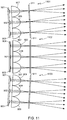
- This aspect of the invention is schematically illustrated in Fig. 12 .
- light source 1201 of module 1200 is comprised of nine LEDs divided into three LED groups 1202-1204.
- LED group 1202 is comprised of three LEDs 1205A-1205C;
- LED group 1203 is comprised of three LEDs 1206A-1206C;
- LED group 1204 is comprised of three LEDs 1207A-1207C.
- each LED with an "A” label is represented on the page as the uppermost LED of the corresponding LED group; each LED with a “B” label is represented on the page as the center LED of the corresponding LED group; and each LED with a “C” label is represented on the page as the lowermost LED of the corresponding LED group.
- each group 1202-1204 is a collimation optic 1209-1211, respectively.
- the light emitted by the LEDs and collimated by optics 1209-1211 pass through optical element 1213, where optical element 1213 includes an illumination MLA, an aperture layer, and a projection MLA as previously described.
- the LEDs within module 1200 may or may not be shifted relative to the corresponding collimating optics as described above relative to Fig.
- the collimation optics 1209-1211 and the illumination and projection MLAs comprising element 1213 direct the light emitted by a first set of LEDs (i.e., LEDs 1205B, 1206B and 1207B) in a first direction such that when these LEDs are activated, the illumination distribution at horizon plane 1215 is approximately centered relative to the light module's centerline as shown by ray tracing group 1217.
- a first set of LEDs i.e., LEDs 1205B, 1206B and 1207B
- the collimation optics 1209-1211 and the illumination element 1213 directs the light emitted by a second set of LEDs (i.e., LEDs 1205C, 1206C and 1207C) in a second direction such that when these LEDs are activated, the illumination distribution at horizon plane 1215 is moved off-center as shown by ray tracing group 1219.
- a second set of LEDs i.e., LEDs 1205C, 1206C and 1207C
- two different regions can be illuminated individually by selectively activating different sets of LEDs, or both regions can be simultaneously illuminated by simultaneously activating both sets of LEDs.
- a single light module is not limited to two illumination regions, rather a single light module can illuminate more than two regions if desired.
- any region of the FoV can be illuminated as desired. Additional lighting flexibility, not only in terms of illumination region within the FoV, but also in terms of illumination homogeneity and intensity, can be achieved through the use of multiple light modules.
- Figs. 13A-C illustrate three different (angular) illumination intensity distributions generated by three different LED sets contained within the same light module.
- the FoV is represented by 1301
- the illumination is represented by (angular) illumination intensity profiles 1303-1306, where profile 1303 represents the highest illumination intensity with a fall-off in intensity represented by profiles 1304-1306, where profile 1306 represents the lowest illustrated illumination intensity.
- the aperture layer used in this exemplary configuration creates an illumination cut-offline 1307, where the cut-off includes a kink 1309 that aids in shielding on-coming cars from the light.
- the intensity profile generated by the first set of LEDs is to the left of kink 1309; the intensity profile generated by the second set of LEDs is centered on kink 1309; and the intensity profile generated by the third set of LEDs is to the right of kink 1309.
Landscapes
- Engineering & Computer Science (AREA)
- Physics & Mathematics (AREA)
- General Engineering & Computer Science (AREA)
- Optics & Photonics (AREA)
- General Physics & Mathematics (AREA)
- Microelectronics & Electronic Packaging (AREA)
- Mechanical Engineering (AREA)
- Mathematical Physics (AREA)
- Non-Portable Lighting Devices Or Systems Thereof (AREA)
- Lighting Device Outwards From Vehicle And Optical Signal (AREA)
Applications Claiming Priority (1)
| Application Number | Priority Date | Filing Date | Title |
|---|---|---|---|
| US15/822,951 US10232763B1 (en) | 2017-11-27 | 2017-11-27 | Solid state adaptive headlight |
Publications (2)
| Publication Number | Publication Date |
|---|---|
| EP3489574A1 true EP3489574A1 (fr) | 2019-05-29 |
| EP3489574B1 EP3489574B1 (fr) | 2022-02-23 |
Family
ID=63878325
Family Applications (1)
| Application Number | Title | Priority Date | Filing Date |
|---|---|---|---|
| EP18200095.0A Active EP3489574B1 (fr) | 2017-11-27 | 2018-10-12 | Phare adaptatif à semi-conducteur |
Country Status (3)
| Country | Link |
|---|---|
| US (1) | US10232763B1 (fr) |
| EP (1) | EP3489574B1 (fr) |
| CN (2) | CN209762926U (fr) |
Cited By (1)
| Publication number | Priority date | Publication date | Assignee | Title |
|---|---|---|---|---|
| DE102018216432B4 (de) * | 2018-09-26 | 2026-02-12 | Sl Corporation | Fahrzeugleuchte |
Families Citing this family (38)
| Publication number | Priority date | Publication date | Assignee | Title |
|---|---|---|---|---|
| US10232763B1 (en) * | 2017-11-27 | 2019-03-19 | Atieva, Inc. | Solid state adaptive headlight |
| JP7042616B2 (ja) * | 2017-12-28 | 2022-03-28 | スタンレー電気株式会社 | 車両用灯具 |
| US10634307B2 (en) * | 2018-09-06 | 2020-04-28 | Sl Corporation | Lamp for vehicle |
| KR20200080838A (ko) * | 2018-12-27 | 2020-07-07 | 에스엘 주식회사 | 차량용 램프 |
| KR20200141248A (ko) | 2019-06-10 | 2020-12-18 | 에스엘 주식회사 | 차량용 램프 |
| FR3099541B1 (fr) * | 2019-07-31 | 2024-09-20 | Valeo Vision | Procede de contrôle d’un dispositif lumineux apte a emettre deux faisceaux lumineux pixelises de resolutions differentes |
| KR102694059B1 (ko) * | 2019-09-20 | 2024-08-09 | 현대모비스 주식회사 | 헤드램프의 광학모듈 |
| US11872929B2 (en) * | 2020-01-14 | 2024-01-16 | Qualcomm Incorporated | Collaborative vehicle headlight directing |
| KR20210108553A (ko) * | 2020-02-25 | 2021-09-03 | 현대자동차주식회사 | 복수의 빔패턴 이미지를 갖는 광원 장치 |
| DE102020112316A1 (de) | 2020-05-06 | 2021-11-11 | Suss Microoptics Sa | Projektionssystem und Fahrzeug mit Projektionssystem |
| JP7307031B2 (ja) * | 2020-05-29 | 2023-07-11 | 株式会社日立エルジーデータストレージ | 虚像投射装置 |
| KR102899332B1 (ko) * | 2020-07-21 | 2025-12-15 | 에스엘 주식회사 | 차량용 램프 |
| CN112004301A (zh) * | 2020-08-24 | 2020-11-27 | 佛山市银河兰晶照明电器有限公司 | 自适应灯具的控制方法、控制系统及自适应灯具 |
| DE102020122896A1 (de) | 2020-09-02 | 2022-03-03 | HELLA GmbH & Co. KGaA | Beleuchtungsvorrichtung für ein Kraftfahrzeug |
| CN114690522A (zh) * | 2020-12-31 | 2022-07-01 | 苏州晶方光电科技有限公司 | 一种光学投影灯 |
| DE102021103514B4 (de) | 2021-02-15 | 2022-10-27 | Volkswagen Aktiengesellschaft | Verfahren zur konfiguration eines scheinwerfersystems für ein fahrzeug |
| CN112963797A (zh) * | 2021-03-19 | 2021-06-15 | 蔚来汽车科技(安徽)有限公司 | 基于红外光源的车辆照明系统及车辆 |
| US11204147B1 (en) * | 2021-04-20 | 2021-12-21 | GM Global Technology Operations LLC | Headlight unit having micro-light emitting diode device, relay lens system and projection lens system |
| FR3124845B1 (fr) | 2021-06-30 | 2023-08-11 | Valeo Vision | Module d’éclairage automobile mulitfonction á réseau de lentilles |
| DE102021122953B3 (de) | 2021-09-06 | 2022-12-22 | HELLA GmbH & Co. KGaA | Beleuchtungsvorrichtung für ein Kraftfahrzeug |
| CN113799685B (zh) * | 2021-09-17 | 2023-04-11 | 东风汽车集团股份有限公司 | Adb大灯亮度和光区自适应调节方法及装置 |
| DE102021124222B4 (de) | 2021-09-20 | 2025-02-20 | HELLA GmbH & Co. KGaA | Beleuchtungsvorrichtung für Fahrzeuge |
| US20240426451A1 (en) * | 2021-10-29 | 2024-12-26 | Atieva, Inc. | Arrangement of light shaping optical elements for automotive signal lighting |
| KR20230155711A (ko) * | 2022-05-04 | 2023-11-13 | 현대모비스 주식회사 | 차량용 램프 |
| KR20240039872A (ko) * | 2022-09-20 | 2024-03-27 | 현대모비스 주식회사 | 차량용 램프 |
| EP4343388A1 (fr) | 2022-09-26 | 2024-03-27 | SUSS MicroOptics SA | Éclairage décoratif avec dispositifs d'éclairage réfractifs et diffractifs |
| FR3141507B1 (fr) * | 2022-10-30 | 2025-02-14 | Valeo Vision | Dispositif lumineux configuré pour réaliser une pluralité de fonctions lumineuses. |
| FR3141506B1 (fr) * | 2022-10-30 | 2025-02-14 | Valeo Vision | Dispositif lumineux configuré pour réaliser au moins deux fonctions lumineuses. |
| EP4616115A1 (fr) | 2022-11-08 | 2025-09-17 | Atieva, Inc. | Phare adaptatif à semi-conducteurs à contraste élevé |
| US11971148B1 (en) * | 2022-11-08 | 2024-04-30 | Atieva, Inc. | High contrast solid state adaptive headlight |
| DE102022131869A1 (de) * | 2022-12-01 | 2023-04-20 | FEV Group GmbH | Projektionsvorrichtung zum erzeugen dynamischer projektionen |
| KR20250009177A (ko) * | 2023-07-10 | 2025-01-17 | 현대모비스 주식회사 | 광학모듈 및 이를 포함하는 차량용 램프 |
| CN119713171A (zh) * | 2023-09-28 | 2025-03-28 | 比亚迪股份有限公司 | 近光灯模组、近光灯和车辆 |
| WO2025093452A1 (fr) * | 2023-10-31 | 2025-05-08 | Valeo Vision | Module lumineux avec matrice de micro-lentilles anamorphiques |
| FR3157519A1 (fr) * | 2023-12-22 | 2025-06-27 | Valeo Vision | Module lumineux pour véhicule automobile |
| WO2025142368A1 (fr) * | 2023-12-27 | 2025-07-03 | 株式会社小糸製作所 | Phare de véhicule |
| WO2025140962A1 (fr) * | 2023-12-28 | 2025-07-03 | Valeo Vision | Dispositif lumineux configuré pour suivre un galbe de véhicule |
| DE102024100194A1 (de) * | 2024-01-04 | 2025-07-10 | HELLA GmbH & Co. KGaA | Beleuchtungsvorrichtung für ein Kraftfahrzeug |
Citations (6)
| Publication number | Priority date | Publication date | Assignee | Title |
|---|---|---|---|---|
| US20030147252A1 (en) * | 2002-02-06 | 2003-08-07 | Fioravanti S.R.L. | Front lighting system for a motor vehicle |
| WO2015058227A1 (fr) * | 2013-10-25 | 2015-04-30 | Zizala Lichtsysteme Gmbh | Module d'éclairage à micro-projection destiné à un projecteur de véhicule automobile |
| DE102014207750A1 (de) * | 2014-04-24 | 2015-10-29 | Osram Opto Semiconductors Gmbh | Beleuchtungsanordnung |
| DE112014006794T5 (de) * | 2014-07-08 | 2017-03-23 | Mitsubishi Electric Corporation | Scheinwerfermodul und Scheinwerfereinrichtung |
| WO2017066818A1 (fr) * | 2015-10-23 | 2017-04-27 | Zkw Group Gmbh | Module lumineux à microprojection pour un projecteur de véhicule à moteur servant à produire des répartitions de lumière sans aberration |
| DE102016112617B3 (de) * | 2016-07-08 | 2017-10-26 | Automotive Lighting Reutlingen Gmbh | Kraftfahrzeugscheinwerfer mit geringer Bautiefe |
Family Cites Families (8)
| Publication number | Priority date | Publication date | Assignee | Title |
|---|---|---|---|---|
| US6155694A (en) * | 1998-04-16 | 2000-12-05 | Whelen Engineering Company, Inc. | Composite warning light with emission pattern matching |
| JP4513653B2 (ja) | 2004-12-27 | 2010-07-28 | 日本ビクター株式会社 | マイクロレンズアレイシートの製造方法 |
| JP5577138B2 (ja) | 2010-04-08 | 2014-08-20 | スタンレー電気株式会社 | 車両用前照灯 |
| US9664352B2 (en) | 2012-11-08 | 2017-05-30 | Docter Optics Se | Headlight lens for a vehicle headlight |
| FR3046833B1 (fr) | 2016-01-20 | 2020-02-07 | Aml Systems | Mecanisme de coupure pour projecteur de vehicule automobile, actionne par un electroaimant a deux entrefers. |
| JP2017162760A (ja) | 2016-03-11 | 2017-09-14 | スタンレー電気株式会社 | 車両用前照灯装置 |
| JP6725282B2 (ja) | 2016-03-25 | 2020-07-15 | スタンレー電気株式会社 | 車両用灯具 |
| US10232763B1 (en) * | 2017-11-27 | 2019-03-19 | Atieva, Inc. | Solid state adaptive headlight |
-
2017
- 2017-11-27 US US15/822,951 patent/US10232763B1/en active Active
-
2018
- 2018-10-12 EP EP18200095.0A patent/EP3489574B1/fr active Active
- 2018-11-23 CN CN201821948813.3U patent/CN209762926U/zh not_active Expired - Fee Related
- 2018-11-23 CN CN201811407757.7A patent/CN109838750B/zh not_active Expired - Fee Related
Patent Citations (6)
| Publication number | Priority date | Publication date | Assignee | Title |
|---|---|---|---|---|
| US20030147252A1 (en) * | 2002-02-06 | 2003-08-07 | Fioravanti S.R.L. | Front lighting system for a motor vehicle |
| WO2015058227A1 (fr) * | 2013-10-25 | 2015-04-30 | Zizala Lichtsysteme Gmbh | Module d'éclairage à micro-projection destiné à un projecteur de véhicule automobile |
| DE102014207750A1 (de) * | 2014-04-24 | 2015-10-29 | Osram Opto Semiconductors Gmbh | Beleuchtungsanordnung |
| DE112014006794T5 (de) * | 2014-07-08 | 2017-03-23 | Mitsubishi Electric Corporation | Scheinwerfermodul und Scheinwerfereinrichtung |
| WO2017066818A1 (fr) * | 2015-10-23 | 2017-04-27 | Zkw Group Gmbh | Module lumineux à microprojection pour un projecteur de véhicule à moteur servant à produire des répartitions de lumière sans aberration |
| DE102016112617B3 (de) * | 2016-07-08 | 2017-10-26 | Automotive Lighting Reutlingen Gmbh | Kraftfahrzeugscheinwerfer mit geringer Bautiefe |
Cited By (1)
| Publication number | Priority date | Publication date | Assignee | Title |
|---|---|---|---|---|
| DE102018216432B4 (de) * | 2018-09-26 | 2026-02-12 | Sl Corporation | Fahrzeugleuchte |
Also Published As
| Publication number | Publication date |
|---|---|
| US10232763B1 (en) | 2019-03-19 |
| CN109838750B (zh) | 2022-03-22 |
| EP3489574B1 (fr) | 2022-02-23 |
| CN109838750A (zh) | 2019-06-04 |
| CN209762926U (zh) | 2019-12-10 |
Similar Documents
| Publication | Publication Date | Title |
|---|---|---|
| EP3489574B1 (fr) | Phare adaptatif à semi-conducteur | |
| US12222077B2 (en) | Vehicle external illumination device | |
| JP7814579B2 (ja) | 車両 | |
| CN108343925B (zh) | 车辆大灯 | |
| US9068711B2 (en) | Headlamp for vehicle which produces glare-free high beam | |
| EP2085264B1 (fr) | Appareil de phare d'automobile et procédé de commande | |
| US11280463B2 (en) | Projection apparatus, lighting module and motor vehicle headlamp consisting of micro-optical systems | |
| KR101749467B1 (ko) | 차량용 헤드라이트 장치의 제어 방법 및 헤드라이트 장치 | |
| US20170227182A1 (en) | Vehicular lighting apparatus | |
| US9902308B2 (en) | Vehicle lighting system | |
| US9995452B2 (en) | Light device, especially a headlight for motor vehicles | |
| EP3847055B1 (fr) | Projecteur adaptatif pour la mise en forme optique et électronique d'une lumière | |
| US20170088036A1 (en) | Headlamp device for a vehicle and method for controlling the headlamp device | |
| CN103765086A (zh) | 车辆用前照灯装置 | |
| KR20200006500A (ko) | 모듈 구성형 자동차 헤드램프 광 모듈 | |
| EP4191127B1 (fr) | Dispositif d'éclairage pour phare de motocyclette | |
| CN109488986B (zh) | 用于机动车辆的光模块和设置有这种模块的照明和/或信号指示装置 | |
| KR101928139B1 (ko) | 헤드업 디스플레이 장치 | |
| CN107002969B (zh) | 用于车辆的大灯 | |
| JP4875519B2 (ja) | 視線誘導用照明装置 | |
| US11719403B2 (en) | Primary optics for motorcycle headlamp | |
| Omerbegovic et al. | Construction zone light: A study on safety and distraction | |
| CN116848020A (zh) | 路面描绘装置 |
Legal Events
| Date | Code | Title | Description |
|---|---|---|---|
| PUAI | Public reference made under article 153(3) epc to a published international application that has entered the european phase |
Free format text: ORIGINAL CODE: 0009012 |
|
| STAA | Information on the status of an ep patent application or granted ep patent |
Free format text: STATUS: REQUEST FOR EXAMINATION WAS MADE |
|
| 17P | Request for examination filed |
Effective date: 20181012 |
|
| AK | Designated contracting states |
Kind code of ref document: A1 Designated state(s): AL AT BE BG CH CY CZ DE DK EE ES FI FR GB GR HR HU IE IS IT LI LT LU LV MC MK MT NL NO PL PT RO RS SE SI SK SM TR |
|
| AX | Request for extension of the european patent |
Extension state: BA ME |
|
| RBV | Designated contracting states (corrected) |
Designated state(s): AL AT BE BG CH CY CZ DE DK EE ES FI FR GB GR HR HU IE IS IT LI LT LU LV MC MK MT NL NO PL PT RO RS SE SI SK SM TR |
|
| GRAP | Despatch of communication of intention to grant a patent |
Free format text: ORIGINAL CODE: EPIDOSNIGR1 |
|
| STAA | Information on the status of an ep patent application or granted ep patent |
Free format text: STATUS: GRANT OF PATENT IS INTENDED |
|
| INTG | Intention to grant announced |
Effective date: 20211008 |
|
| GRAS | Grant fee paid |
Free format text: ORIGINAL CODE: EPIDOSNIGR3 |
|
| GRAA | (expected) grant |
Free format text: ORIGINAL CODE: 0009210 |
|
| STAA | Information on the status of an ep patent application or granted ep patent |
Free format text: STATUS: THE PATENT HAS BEEN GRANTED |
|
| AK | Designated contracting states |
Kind code of ref document: B1 Designated state(s): AL AT BE BG CH CY CZ DE DK EE ES FI FR GB GR HR HU IE IS IT LI LT LU LV MC MK MT NL NO PL PT RO RS SE SI SK SM TR |
|
| REG | Reference to a national code |
Ref country code: GB Ref legal event code: FG4D |
|
| REG | Reference to a national code |
Ref country code: CH Ref legal event code: EP |
|
| REG | Reference to a national code |
Ref country code: AT Ref legal event code: REF Ref document number: 1470732 Country of ref document: AT Kind code of ref document: T Effective date: 20220315 |
|
| REG | Reference to a national code |
Ref country code: IE Ref legal event code: FG4D |
|
| REG | Reference to a national code |
Ref country code: DE Ref legal event code: R096 Ref document number: 602018031146 Country of ref document: DE |
|
| REG | Reference to a national code |
Ref country code: NL Ref legal event code: FP |
|
| REG | Reference to a national code |
Ref country code: LT Ref legal event code: MG9D |
|
| REG | Reference to a national code |
Ref country code: AT Ref legal event code: MK05 Ref document number: 1470732 Country of ref document: AT Kind code of ref document: T Effective date: 20220223 |
|
| PG25 | Lapsed in a contracting state [announced via postgrant information from national office to epo] |
Ref country code: SE Free format text: LAPSE BECAUSE OF FAILURE TO SUBMIT A TRANSLATION OF THE DESCRIPTION OR TO PAY THE FEE WITHIN THE PRESCRIBED TIME-LIMIT Effective date: 20220223 Ref country code: RS Free format text: LAPSE BECAUSE OF FAILURE TO SUBMIT A TRANSLATION OF THE DESCRIPTION OR TO PAY THE FEE WITHIN THE PRESCRIBED TIME-LIMIT Effective date: 20220223 Ref country code: PT Free format text: LAPSE BECAUSE OF FAILURE TO SUBMIT A TRANSLATION OF THE DESCRIPTION OR TO PAY THE FEE WITHIN THE PRESCRIBED TIME-LIMIT Effective date: 20220623 Ref country code: NO Free format text: LAPSE BECAUSE OF FAILURE TO SUBMIT A TRANSLATION OF THE DESCRIPTION OR TO PAY THE FEE WITHIN THE PRESCRIBED TIME-LIMIT Effective date: 20220523 Ref country code: LT Free format text: LAPSE BECAUSE OF FAILURE TO SUBMIT A TRANSLATION OF THE DESCRIPTION OR TO PAY THE FEE WITHIN THE PRESCRIBED TIME-LIMIT Effective date: 20220223 Ref country code: HR Free format text: LAPSE BECAUSE OF FAILURE TO SUBMIT A TRANSLATION OF THE DESCRIPTION OR TO PAY THE FEE WITHIN THE PRESCRIBED TIME-LIMIT Effective date: 20220223 Ref country code: ES Free format text: LAPSE BECAUSE OF FAILURE TO SUBMIT A TRANSLATION OF THE DESCRIPTION OR TO PAY THE FEE WITHIN THE PRESCRIBED TIME-LIMIT Effective date: 20220223 Ref country code: BG Free format text: LAPSE BECAUSE OF FAILURE TO SUBMIT A TRANSLATION OF THE DESCRIPTION OR TO PAY THE FEE WITHIN THE PRESCRIBED TIME-LIMIT Effective date: 20220523 |
|
| PG25 | Lapsed in a contracting state [announced via postgrant information from national office to epo] |
Ref country code: PL Free format text: LAPSE BECAUSE OF FAILURE TO SUBMIT A TRANSLATION OF THE DESCRIPTION OR TO PAY THE FEE WITHIN THE PRESCRIBED TIME-LIMIT Effective date: 20220223 Ref country code: LV Free format text: LAPSE BECAUSE OF FAILURE TO SUBMIT A TRANSLATION OF THE DESCRIPTION OR TO PAY THE FEE WITHIN THE PRESCRIBED TIME-LIMIT Effective date: 20220223 Ref country code: GR Free format text: LAPSE BECAUSE OF FAILURE TO SUBMIT A TRANSLATION OF THE DESCRIPTION OR TO PAY THE FEE WITHIN THE PRESCRIBED TIME-LIMIT Effective date: 20220524 Ref country code: FI Free format text: LAPSE BECAUSE OF FAILURE TO SUBMIT A TRANSLATION OF THE DESCRIPTION OR TO PAY THE FEE WITHIN THE PRESCRIBED TIME-LIMIT Effective date: 20220223 Ref country code: AT Free format text: LAPSE BECAUSE OF FAILURE TO SUBMIT A TRANSLATION OF THE DESCRIPTION OR TO PAY THE FEE WITHIN THE PRESCRIBED TIME-LIMIT Effective date: 20220223 |
|
| PG25 | Lapsed in a contracting state [announced via postgrant information from national office to epo] |
Ref country code: IS Free format text: LAPSE BECAUSE OF FAILURE TO SUBMIT A TRANSLATION OF THE DESCRIPTION OR TO PAY THE FEE WITHIN THE PRESCRIBED TIME-LIMIT Effective date: 20220623 |
|
| PG25 | Lapsed in a contracting state [announced via postgrant information from national office to epo] |
Ref country code: SM Free format text: LAPSE BECAUSE OF FAILURE TO SUBMIT A TRANSLATION OF THE DESCRIPTION OR TO PAY THE FEE WITHIN THE PRESCRIBED TIME-LIMIT Effective date: 20220223 Ref country code: SK Free format text: LAPSE BECAUSE OF FAILURE TO SUBMIT A TRANSLATION OF THE DESCRIPTION OR TO PAY THE FEE WITHIN THE PRESCRIBED TIME-LIMIT Effective date: 20220223 Ref country code: RO Free format text: LAPSE BECAUSE OF FAILURE TO SUBMIT A TRANSLATION OF THE DESCRIPTION OR TO PAY THE FEE WITHIN THE PRESCRIBED TIME-LIMIT Effective date: 20220223 Ref country code: EE Free format text: LAPSE BECAUSE OF FAILURE TO SUBMIT A TRANSLATION OF THE DESCRIPTION OR TO PAY THE FEE WITHIN THE PRESCRIBED TIME-LIMIT Effective date: 20220223 Ref country code: DK Free format text: LAPSE BECAUSE OF FAILURE TO SUBMIT A TRANSLATION OF THE DESCRIPTION OR TO PAY THE FEE WITHIN THE PRESCRIBED TIME-LIMIT Effective date: 20220223 Ref country code: CZ Free format text: LAPSE BECAUSE OF FAILURE TO SUBMIT A TRANSLATION OF THE DESCRIPTION OR TO PAY THE FEE WITHIN THE PRESCRIBED TIME-LIMIT Effective date: 20220223 |
|
| REG | Reference to a national code |
Ref country code: DE Ref legal event code: R097 Ref document number: 602018031146 Country of ref document: DE |
|
| PG25 | Lapsed in a contracting state [announced via postgrant information from national office to epo] |
Ref country code: AL Free format text: LAPSE BECAUSE OF FAILURE TO SUBMIT A TRANSLATION OF THE DESCRIPTION OR TO PAY THE FEE WITHIN THE PRESCRIBED TIME-LIMIT Effective date: 20220223 |
|
| PLBE | No opposition filed within time limit |
Free format text: ORIGINAL CODE: 0009261 |
|
| STAA | Information on the status of an ep patent application or granted ep patent |
Free format text: STATUS: NO OPPOSITION FILED WITHIN TIME LIMIT |
|
| 26N | No opposition filed |
Effective date: 20221124 |
|
| PG25 | Lapsed in a contracting state [announced via postgrant information from national office to epo] |
Ref country code: SI Free format text: LAPSE BECAUSE OF FAILURE TO SUBMIT A TRANSLATION OF THE DESCRIPTION OR TO PAY THE FEE WITHIN THE PRESCRIBED TIME-LIMIT Effective date: 20220223 |
|
| PG25 | Lapsed in a contracting state [announced via postgrant information from national office to epo] |
Ref country code: MC Free format text: LAPSE BECAUSE OF FAILURE TO SUBMIT A TRANSLATION OF THE DESCRIPTION OR TO PAY THE FEE WITHIN THE PRESCRIBED TIME-LIMIT Effective date: 20220223 |
|
| REG | Reference to a national code |
Ref country code: CH Ref legal event code: PL |
|
| REG | Reference to a national code |
Ref country code: BE Ref legal event code: MM Effective date: 20221031 |
|
| PG25 | Lapsed in a contracting state [announced via postgrant information from national office to epo] |
Ref country code: LU Free format text: LAPSE BECAUSE OF NON-PAYMENT OF DUE FEES Effective date: 20221012 |
|
| PG25 | Lapsed in a contracting state [announced via postgrant information from national office to epo] |
Ref country code: LI Free format text: LAPSE BECAUSE OF NON-PAYMENT OF DUE FEES Effective date: 20221031 Ref country code: IT Free format text: LAPSE BECAUSE OF FAILURE TO SUBMIT A TRANSLATION OF THE DESCRIPTION OR TO PAY THE FEE WITHIN THE PRESCRIBED TIME-LIMIT Effective date: 20220223 Ref country code: CH Free format text: LAPSE BECAUSE OF NON-PAYMENT OF DUE FEES Effective date: 20221031 |
|
| P01 | Opt-out of the competence of the unified patent court (upc) registered |
Effective date: 20230707 |
|
| PG25 | Lapsed in a contracting state [announced via postgrant information from national office to epo] |
Ref country code: BE Free format text: LAPSE BECAUSE OF NON-PAYMENT OF DUE FEES Effective date: 20221031 |
|
| PG25 | Lapsed in a contracting state [announced via postgrant information from national office to epo] |
Ref country code: IE Free format text: LAPSE BECAUSE OF NON-PAYMENT OF DUE FEES Effective date: 20221012 |
|
| PGFP | Annual fee paid to national office [announced via postgrant information from national office to epo] |
Ref country code: NL Payment date: 20231023 Year of fee payment: 6 |
|
| PGFP | Annual fee paid to national office [announced via postgrant information from national office to epo] |
Ref country code: FR Payment date: 20231030 Year of fee payment: 6 |
|
| PG25 | Lapsed in a contracting state [announced via postgrant information from national office to epo] |
Ref country code: HU Free format text: LAPSE BECAUSE OF FAILURE TO SUBMIT A TRANSLATION OF THE DESCRIPTION OR TO PAY THE FEE WITHIN THE PRESCRIBED TIME-LIMIT; INVALID AB INITIO Effective date: 20181012 |
|
| PG25 | Lapsed in a contracting state [announced via postgrant information from national office to epo] |
Ref country code: CY Free format text: LAPSE BECAUSE OF FAILURE TO SUBMIT A TRANSLATION OF THE DESCRIPTION OR TO PAY THE FEE WITHIN THE PRESCRIBED TIME-LIMIT Effective date: 20220223 |
|
| REG | Reference to a national code |
Ref country code: GB Ref legal event code: S117 Free format text: REQUEST FILED; REQUEST FOR CORRECTION UNDER SECTION 117 FILED ON 08 APRIL 2024 |
|
| PG25 | Lapsed in a contracting state [announced via postgrant information from national office to epo] |
Ref country code: MK Free format text: LAPSE BECAUSE OF FAILURE TO SUBMIT A TRANSLATION OF THE DESCRIPTION OR TO PAY THE FEE WITHIN THE PRESCRIBED TIME-LIMIT Effective date: 20220223 |
|
| REG | Reference to a national code |
Ref country code: GB Ref legal event code: S117 Free format text: REQUEST FOR CORRECTION UNDER SECTION 117 FILED ON 8 APRIL 2024 WAS NOT PROCEEDED WITH ON 29 MAY 2024 |
|
| PG25 | Lapsed in a contracting state [announced via postgrant information from national office to epo] |
Ref country code: TR Free format text: LAPSE BECAUSE OF FAILURE TO SUBMIT A TRANSLATION OF THE DESCRIPTION OR TO PAY THE FEE WITHIN THE PRESCRIBED TIME-LIMIT Effective date: 20220223 |
|
| REG | Reference to a national code |
Ref country code: DE Ref legal event code: R083 Ref document number: 602018031146 Country of ref document: DE |
|
| PG25 | Lapsed in a contracting state [announced via postgrant information from national office to epo] |
Ref country code: MT Free format text: LAPSE BECAUSE OF FAILURE TO SUBMIT A TRANSLATION OF THE DESCRIPTION OR TO PAY THE FEE WITHIN THE PRESCRIBED TIME-LIMIT Effective date: 20220223 |
|
| REG | Reference to a national code |
Ref country code: GB Ref legal event code: S13A Free format text: APPLICATION FILED; APPLICATION UNDER RULE 10(2) FOR INVENTOR TO BE MENTIONED FILED ON 18 SEPTEMBER 2024 BY ATIEVA, INC. |
|
| REG | Reference to a national code |
Ref country code: GB Ref legal event code: S13A Free format text: APPLICATION ALLOWED; IN A DECISION OF THE COMPTROLLER DATED 17 OCTOBER 2024, THE COMPTROLLER FOUND THAT MARCEL SIELER SHOULD BE MENTIONED AS A JOINT INVENTOR IN RESPECT OF GRANTED PATENT EP3489574. THE COMPTROLLER ORDERED THAT AN ADDENDUM SLIP BE PREPARED FOR THE GRANTED PATENT ACCORDINGLY |
|
| REG | Reference to a national code |
Ref country code: NL Ref legal event code: MM Effective date: 20241101 |
|
| PG25 | Lapsed in a contracting state [announced via postgrant information from national office to epo] |
Ref country code: NL Free format text: LAPSE BECAUSE OF NON-PAYMENT OF DUE FEES Effective date: 20241101 |
|
| PG25 | Lapsed in a contracting state [announced via postgrant information from national office to epo] |
Ref country code: FR Free format text: LAPSE BECAUSE OF NON-PAYMENT OF DUE FEES Effective date: 20241031 |
|
| PGFP | Annual fee paid to national office [announced via postgrant information from national office to epo] |
Ref country code: DE Payment date: 20251020 Year of fee payment: 8 |
|
| PGFP | Annual fee paid to national office [announced via postgrant information from national office to epo] |
Ref country code: GB Payment date: 20251024 Year of fee payment: 8 |
|
| REG | Reference to a national code |
Ref country code: DE Ref legal event code: R082 Ref document number: 602018031146 Country of ref document: DE Representative=s name: GULDE & PARTNER PATENT- UND RECHTSANWALTSKANZL, DE |