EP3489576B1 - Leuchtmodul zur beleuchtung und/oder signalisierung eines kraftfahrzeugs - Google Patents
Leuchtmodul zur beleuchtung und/oder signalisierung eines kraftfahrzeugs Download PDFInfo
- Publication number
- EP3489576B1 EP3489576B1 EP18208370.9A EP18208370A EP3489576B1 EP 3489576 B1 EP3489576 B1 EP 3489576B1 EP 18208370 A EP18208370 A EP 18208370A EP 3489576 B1 EP3489576 B1 EP 3489576B1
- Authority
- EP
- European Patent Office
- Prior art keywords
- face
- optical device
- primary optical
- lighting module
- light
- Prior art date
- Legal status (The legal status is an assumption and is not a legal conclusion. Google has not performed a legal analysis and makes no representation as to the accuracy of the status listed.)
- Active
Links
Images



Classifications
-
- F—MECHANICAL ENGINEERING; LIGHTING; HEATING; WEAPONS; BLASTING
- F21—LIGHTING
- F21S—NON-PORTABLE LIGHTING DEVICES; SYSTEMS THEREOF; VEHICLE LIGHTING DEVICES SPECIALLY ADAPTED FOR VEHICLE EXTERIORS
- F21S41/00—Illuminating devices specially adapted for vehicle exteriors, e.g. headlamps
- F21S41/20—Illuminating devices specially adapted for vehicle exteriors, e.g. headlamps characterised by refractors, transparent cover plates, light guides or filters
- F21S41/29—Attachment thereof
-
- F—MECHANICAL ENGINEERING; LIGHTING; HEATING; WEAPONS; BLASTING
- F21—LIGHTING
- F21S—NON-PORTABLE LIGHTING DEVICES; SYSTEMS THEREOF; VEHICLE LIGHTING DEVICES SPECIALLY ADAPTED FOR VEHICLE EXTERIORS
- F21S41/00—Illuminating devices specially adapted for vehicle exteriors, e.g. headlamps
- F21S41/10—Illuminating devices specially adapted for vehicle exteriors, e.g. headlamps characterised by the light source
- F21S41/14—Illuminating devices specially adapted for vehicle exteriors, e.g. headlamps characterised by the light source characterised by the type of light source
- F21S41/141—Light emitting diodes [LED]
- F21S41/143—Light emitting diodes [LED] the main emission direction of the LED being parallel to the optical axis of the illuminating device
-
- F—MECHANICAL ENGINEERING; LIGHTING; HEATING; WEAPONS; BLASTING
- F21—LIGHTING
- F21S—NON-PORTABLE LIGHTING DEVICES; SYSTEMS THEREOF; VEHICLE LIGHTING DEVICES SPECIALLY ADAPTED FOR VEHICLE EXTERIORS
- F21S41/00—Illuminating devices specially adapted for vehicle exteriors, e.g. headlamps
- F21S41/10—Illuminating devices specially adapted for vehicle exteriors, e.g. headlamps characterised by the light source
- F21S41/14—Illuminating devices specially adapted for vehicle exteriors, e.g. headlamps characterised by the light source characterised by the type of light source
- F21S41/141—Light emitting diodes [LED]
- F21S41/151—Light emitting diodes [LED] arranged in one or more lines
- F21S41/153—Light emitting diodes [LED] arranged in one or more lines arranged in a matrix
-
- F—MECHANICAL ENGINEERING; LIGHTING; HEATING; WEAPONS; BLASTING
- F21—LIGHTING
- F21S—NON-PORTABLE LIGHTING DEVICES; SYSTEMS THEREOF; VEHICLE LIGHTING DEVICES SPECIALLY ADAPTED FOR VEHICLE EXTERIORS
- F21S41/00—Illuminating devices specially adapted for vehicle exteriors, e.g. headlamps
- F21S41/10—Illuminating devices specially adapted for vehicle exteriors, e.g. headlamps characterised by the light source
- F21S41/19—Attachment of light sources or lamp holders
-
- F—MECHANICAL ENGINEERING; LIGHTING; HEATING; WEAPONS; BLASTING
- F21—LIGHTING
- F21S—NON-PORTABLE LIGHTING DEVICES; SYSTEMS THEREOF; VEHICLE LIGHTING DEVICES SPECIALLY ADAPTED FOR VEHICLE EXTERIORS
- F21S41/00—Illuminating devices specially adapted for vehicle exteriors, e.g. headlamps
- F21S41/10—Illuminating devices specially adapted for vehicle exteriors, e.g. headlamps characterised by the light source
- F21S41/19—Attachment of light sources or lamp holders
- F21S41/192—Details of lamp holders, terminals or connectors
-
- F—MECHANICAL ENGINEERING; LIGHTING; HEATING; WEAPONS; BLASTING
- F21—LIGHTING
- F21S—NON-PORTABLE LIGHTING DEVICES; SYSTEMS THEREOF; VEHICLE LIGHTING DEVICES SPECIALLY ADAPTED FOR VEHICLE EXTERIORS
- F21S41/00—Illuminating devices specially adapted for vehicle exteriors, e.g. headlamps
- F21S41/20—Illuminating devices specially adapted for vehicle exteriors, e.g. headlamps characterised by refractors, transparent cover plates, light guides or filters
- F21S41/24—Light guides
-
- F—MECHANICAL ENGINEERING; LIGHTING; HEATING; WEAPONS; BLASTING
- F21—LIGHTING
- F21S—NON-PORTABLE LIGHTING DEVICES; SYSTEMS THEREOF; VEHICLE LIGHTING DEVICES SPECIALLY ADAPTED FOR VEHICLE EXTERIORS
- F21S41/00—Illuminating devices specially adapted for vehicle exteriors, e.g. headlamps
- F21S41/30—Illuminating devices specially adapted for vehicle exteriors, e.g. headlamps characterised by reflectors
- F21S41/32—Optical layout thereof
- F21S41/322—Optical layout thereof the reflector using total internal reflection
-
- F—MECHANICAL ENGINEERING; LIGHTING; HEATING; WEAPONS; BLASTING
- F21—LIGHTING
- F21S—NON-PORTABLE LIGHTING DEVICES; SYSTEMS THEREOF; VEHICLE LIGHTING DEVICES SPECIALLY ADAPTED FOR VEHICLE EXTERIORS
- F21S41/00—Illuminating devices specially adapted for vehicle exteriors, e.g. headlamps
- F21S41/40—Illuminating devices specially adapted for vehicle exteriors, e.g. headlamps characterised by screens, non-reflecting members, light-shielding members or fixed shades
- F21S41/43—Illuminating devices specially adapted for vehicle exteriors, e.g. headlamps characterised by screens, non-reflecting members, light-shielding members or fixed shades characterised by the shape thereof
-
- F—MECHANICAL ENGINEERING; LIGHTING; HEATING; WEAPONS; BLASTING
- F21—LIGHTING
- F21S—NON-PORTABLE LIGHTING DEVICES; SYSTEMS THEREOF; VEHICLE LIGHTING DEVICES SPECIALLY ADAPTED FOR VEHICLE EXTERIORS
- F21S41/00—Illuminating devices specially adapted for vehicle exteriors, e.g. headlamps
- F21S41/40—Illuminating devices specially adapted for vehicle exteriors, e.g. headlamps characterised by screens, non-reflecting members, light-shielding members or fixed shades
- F21S41/47—Attachment thereof
-
- F—MECHANICAL ENGINEERING; LIGHTING; HEATING; WEAPONS; BLASTING
- F21—LIGHTING
- F21S—NON-PORTABLE LIGHTING DEVICES; SYSTEMS THEREOF; VEHICLE LIGHTING DEVICES SPECIALLY ADAPTED FOR VEHICLE EXTERIORS
- F21S41/00—Illuminating devices specially adapted for vehicle exteriors, e.g. headlamps
- F21S41/60—Illuminating devices specially adapted for vehicle exteriors, e.g. headlamps characterised by a variable light distribution
- F21S41/65—Illuminating devices specially adapted for vehicle exteriors, e.g. headlamps characterised by a variable light distribution by acting on light sources
- F21S41/663—Illuminating devices specially adapted for vehicle exteriors, e.g. headlamps characterised by a variable light distribution by acting on light sources by switching light sources
-
- F—MECHANICAL ENGINEERING; LIGHTING; HEATING; WEAPONS; BLASTING
- F21—LIGHTING
- F21S—NON-PORTABLE LIGHTING DEVICES; SYSTEMS THEREOF; VEHICLE LIGHTING DEVICES SPECIALLY ADAPTED FOR VEHICLE EXTERIORS
- F21S43/00—Signalling devices specially adapted for vehicle exteriors, e.g. brake lamps, direction indicator lights or reversing lights
- F21S43/10—Signalling devices specially adapted for vehicle exteriors, e.g. brake lamps, direction indicator lights or reversing lights characterised by the light source
- F21S43/19—Attachment of light sources or lamp holders
- F21S43/195—Details of lamp holders, terminals or connectors
-
- F—MECHANICAL ENGINEERING; LIGHTING; HEATING; WEAPONS; BLASTING
- F21—LIGHTING
- F21S—NON-PORTABLE LIGHTING DEVICES; SYSTEMS THEREOF; VEHICLE LIGHTING DEVICES SPECIALLY ADAPTED FOR VEHICLE EXTERIORS
- F21S45/00—Arrangements within vehicle lighting devices specially adapted for vehicle exteriors, for purposes other than emission or distribution of light
- F21S45/10—Protection of lighting devices
-
- F—MECHANICAL ENGINEERING; LIGHTING; HEATING; WEAPONS; BLASTING
- F21—LIGHTING
- F21S—NON-PORTABLE LIGHTING DEVICES; SYSTEMS THEREOF; VEHICLE LIGHTING DEVICES SPECIALLY ADAPTED FOR VEHICLE EXTERIORS
- F21S41/00—Illuminating devices specially adapted for vehicle exteriors, e.g. headlamps
- F21S41/30—Illuminating devices specially adapted for vehicle exteriors, e.g. headlamps characterised by reflectors
- F21S41/32—Optical layout thereof
- F21S41/36—Combinations of two or more separate reflectors
- F21S41/365—Combinations of two or more separate reflectors successively reflecting the light
-
- F—MECHANICAL ENGINEERING; LIGHTING; HEATING; WEAPONS; BLASTING
- F21—LIGHTING
- F21W—INDEXING SCHEME ASSOCIATED WITH SUBCLASSES F21K, F21L, F21S and F21V, RELATING TO USES OR APPLICATIONS OF LIGHTING DEVICES OR SYSTEMS
- F21W2102/00—Exterior vehicle lighting devices for illuminating purposes
-
- F—MECHANICAL ENGINEERING; LIGHTING; HEATING; WEAPONS; BLASTING
- F21—LIGHTING
- F21W—INDEXING SCHEME ASSOCIATED WITH SUBCLASSES F21K, F21L, F21S and F21V, RELATING TO USES OR APPLICATIONS OF LIGHTING DEVICES OR SYSTEMS
- F21W2103/00—Exterior vehicle lighting devices for signalling purposes
Definitions
- the present invention relates to the field of light modules used for the lighting and/or signaling of motor vehicles (see for example the document US 2009/016074 A ), and it applies more particularly to light modules comprising optical devices for forming different light beams, and in particular a so-called passing beam and a so-called driving beam.
- Automotive headlamps usually consist of a housing which is closed by a transparent wall through which one or more light beams pass.
- This box houses at least one light module, mainly comprising a light source and an optical system configured to conform the light generated by the light source in order to provide specific lighting and/or signaling services for the vehicle.
- the optical system can be configured to allow the projection at the output of the headlight of a so-called dipped light beam, in order in particular to limit glare for the drivers of vehicles traveling in the opposite direction.
- the light module comprises at least one light source, a primary optical device positioned opposite the light source to guide the light rays, a cover element that can form a cutting of the light rays emitted in order to form a partial light beam capable of not dazzling third parties at the output of the headlamp, and a lens for shaping these rays to form the light beam at the output of the headlamp.
- the masking element is arranged on the path of the rays, at a distance from the light source and that it is necessary to ensure the position of the latter in the long term so that the shape given to the rays for the so-called crossing light beam is stable over time.
- additional light modules can be associated in the same headlamp to perform a main beam function, capable of illuminating a road scene with a long range, when the risk of dazzling third parties is not present.
- These additional light modules again comprise one or more light sources and a primary optical device associated with a shaping lens for the projection of the rays.
- light modules are provided in which these two functions are performed, the light sources and the primary optical devices having to be arranged relative to each other to perform these different functions according to the switching on of one and /or the other of the light sources.
- First light sources are switched on when it is appropriate to emit a first beam of the dipped beam type, and second light sources are switched on in addition to emit a beam complementary to this first beam to form, by combining the two beams, a beam of high beam type.
- Such arrangements may involve the placement of primary optical devices, and/or of a masking element, which have a distal end face at a distance from a base forming a support for the light sources. It is understood that the manufacturing clearances of these primary optical devices, produced in series, can generate a positioning error. A manufacturing defect at the base of the primary optical device, and in particular at the place where the base will be fixed to the support, can lead to poor positioning of the device, especially since the overhang is tall. Moreover, it appeared that the mechanical vibrations and the temperature variations to which the light module is exposed during its use can cause over time a variation in the more or less pronounced inclination of these primary optical devices with respect to the light source.
- This inclination has the disadvantage of modifying the area illuminated by the dipped headlights, which can prove to be unpleasant or even dangerous for the drivers of vehicles traveling in reverse. It is then necessary to carry out regular maintenance of the light module in order to correct this defect to prevent any accident.
- the invention proposes to produce a light module comprising a primary optical device whose position is less likely to vary over time with respect to the light source of the light module.
- the subject of the invention is a light module for the lighting and/or signaling of a motor vehicle according to claim 1.
- the terms “receiving part” and “output face” are understood to mean respectively the part of the primary optical device illuminated by the light source and the face of the primary optical device through which this light is emitted in the direction of a shaping lens.
- the light module according to the invention comprises at least one arm projecting from the first face of the base and holding the primary optical device at the level of a holding zone located between the receiving part and the exit face of the primary optical device. In this way, it is possible to limit or prevent the inclination of the primary optical device with respect to the base and to ensure a reliable position of the primary optical device in the light module.
- the invention also covers a motor vehicle headlamp comprising at least one light module as described in this document, in its most limited form or comprising one or more of the characteristics set out above.
- longitudinal or lateral above, below, in front, behind refer to the orientation of the light module 2 as it is intended to be integrated into a motor vehicle headlight.
- a longitudinal direction corresponds to an optical axis A along which the light rays generated by the light module 2 mainly extend.
- the lateral orientation corresponds to a straight line perpendicular to the optical axis A and which extends horizontally.
- the vertical direction corresponds to an orientation perpendicular to the optical axis A and to the lateral orientation.
- the figure 1 illustrates a light module 2 according to the invention, otherwise called an optical module, whose function is to generate and project one or more light beams onto a road.
- a light module 2 is intended to be installed in a headlamp of a motor vehicle not shown in the figures in order to facilitate understanding of the invention.
- the headlamp mentioned here generally comprises a rear casing closed at the front by a transparent glass, the latter being traversed by the light rays created by the light module according to the invention.
- Such a projector can thus receive in its interior volume, delimited by the rear casing and the transparent glass, a plurality of light modules, and at least one light module according to the invention.
- Such a light module 2 forms a unitary sub-assembly, that is to say an object which can fulfill its function without any other input than the electrical energy necessary for its ignition, and if necessary with the aid of a electric current regulation module to protect the module from excessive temperatures.
- the light module 2 is arranged to create a low beam beam and a high beam beam.
- the light module 2 is adapted so that the main beam is the combination of the dipped beam with a complementary beam which illuminates above and/or below the dipped beam, the assembly thus forming the main beam.
- the light module 2 comprises at least one light source 4 in particular visible on the figure 2 . It also comprises at least one lens 6 arranged at one end of the module so as to be traversed by the light rays emitted by the light source 4. Such a shaping lens 6 contributes to the formation of the desired light beam, which this is a low beam type beam or a high beam type beam. In other words, the shaping lens 6 forms a first longitudinal end of the light module 2.
- the figure 1 also shows the presence of a support 8 of shaping lens 6 which has a substantially tubular shape and which extends between a base 10 and the shaping lens 6.
- the lens can be snapped directly onto the support, or else be fixed by means of a fixing ring 11 pressing the shaping lens 6 against a longitudinal end of the support 8.
- This support 8 also provides mechanical referencing of the position of the shaping lens 6 relative to the light source 4, via the base 10, so as to guarantee a determined position of the shaping lens 6 relative to the light source 4.
- the support 8 is in particular formed by two longitudinally consecutive tubular sectors of different cross-section.
- a first tubular sector 12 bears against a first face 14 of the base 10 facing the lens, while a second tubular sector 16 extends the first tubular sector 12 and forms a reception zone for the shaping lens 6.
- the first tubular sector 12 can be flush with a dissipation member 18, intended to evacuate from the light module 2 at least part of the heat generated by the light source 4.
- the support 8 can be secured to the base 10 by the presence of screws pressing the support 8 against the first face 14 of the base 10.
- the picture 2 shows part of the light module 2, and in particular the base 10 without support 8, so as to facilitate understanding of the arrangement in the light module 2 of the light source 4, here composed of a set of components associated in such a way to form three subassemblies capable of supplying one after the other or at the same time light beams.
- the light source 4 therefore comprises several light-emitting diodes 22 of identical or different colors.
- the light emitting diodes 22 are in contact with the first face 14 of the base 10, either directly or through a thermally conductive tab.
- the light module 2 comprises three rows of light-emitting diodes substantially parallel to each other. Each row thus forms a subset of light sources among which a first subset of light sources 24, a second subset of light sources 26 and a third subset of light sources 28 can be distinguished. It is understood that the arrangement illustrated is given by way of example, and that the light-emitting diodes could for example be arranged to form three functional subassemblies without an arrangement in parallel rows being visible on the module.
- the first subset of light sources 24 is responsible for creating the light rays for a first dipped beam type light beam
- the second subset of light sources 26 is responsible for creating the light rays for a complementary light beam forming by addition with the first beam a second beam of the main beam type
- the third subset of light sources 28 is responsible for creating the light rays to super-intensify a central zone at the edge of the second beam, namely the edge forming a junction with the first beam when the two beams are projected simultaneously.
- the first subset of light sources 24 comprises six light-emitting diodes 22, substantially aligned in a lateral direction.
- the second subset of light sources 26 and the third subset of light sources 28 respectively comprise four and two light emitting diodes 22 distributed over two substantially lateral lines, the second subset of light sources 26 being positioned between the first subset of light sources 24 and the third subset of light sources 28.
- Each of the subsets of light sources 24, 26 and 28 is arranged against the first face 14 of the base 10, in a central zone on this first face 14 as is apparent from the picture 2 . This makes it possible to clear around this central zone a peripheral zone to allow the attachment of a frame 30 according to one aspect of the invention.
- the chassis 30 illustrated in figure 2 and 3 comprises a frame 32 defining a closed contour of rectangular shape.
- the dimensions of the frame are adapted so as to allow its positioning around the light source 4 and its holding against the first face 14 of the base 10 by means of screws 20.
- the light source 4 is thus surrounded by the frame 32.
- the shape and dimensions of the frame can be adapted depending on the dimensions and shape of the light source 4.
- the frame 32 has a first face 34 intended to be pressed against the first face 14 of the base 10 when the frame is fixed to the base.
- the frame 30 also comprises two arms 36 extending from the frame 32 in the direction of the shaping lens 6 in a longitudinal or normal direction with respect to the plane defined by this frame 32. results, when the frame 32 is fixed on the base 10, that the arms 36 extend mainly perpendicular to this base 10.
- the arms 36 extend from opposite edges of the frame 32, and they are more particularly positioned at the level of each end of the lateral line formed by the second subset of light sources 26.
- the arms 36 respectively have an inner face 38 facing the opposite arm, such that the inner faces 38 of the arms face each other. screw.
- Each inner face 38 has a groove 40 extending over part of the arm 36. More specifically, each groove 40 extends to emerge on the first face 34 of the frame as illustrated in picture 3 .
- the grooves 40 are preferably identical and of suitable dimensions to allow the guiding of a lug 42 secured to the primary optical device which will be described later.
- Each arm 36 also includes an opening 44 at the level of a distal end 46, the opening 44 being disposed in the longitudinal extension of the groove 40.
- the term "distal” means the end of an arm 36 which is the farthest from the base 10 and the light source 4, and which is therefore the closest to the shaping lens 6.
- the openings 44 cross right through each arm 36.
- the openings 44 are sized to each accommodate a lug 42 as mentioned above after its guidance by a corresponding groove 40. It is understood that unlike the grooves 40, the openings 44 are intended to block the lug in position along the inner face 38 of the arm 36.
- the openings and the lugs are here an embodiment of complementary members carried by the arms of the chassis and by the primary optical device 50 as will be described in more detail below, these complementary members having shapes configured to allow this blocking in position.
- the holding zone 62 is here formed in the vicinity of the distal end 46 of each arm, it being understood that it could be provided more or less far from the exit face 54 with respect to what is illustrated. It is however desirable that this holding zone, to ensure stability of the device, be arranged closer to the exit face 54 at the end of the guide body 53 of the primary optical device than to the receiving part 52 of this primary optical device. 50.
- the frame 30 comprises at its first face 34 notches 48, configured to delimit spaces for receiving tabs 74 integral with optical elements, as will be described below.
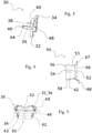
- a light module 2 also comprises at least one primary optical device 50 as illustrated in figure 4 , capable of being arranged directly opposite the light source 4, between the latter and the shaping lens 6.
- this primary optical device 50 participates both in the formation of a light beam of the main beam type, by guiding the light rays inside the optical device, than to the formation of a light beam of the dipped beam type, by cutting off the rays treated elsewhere by another primary optical device.
- the primary optical device 50 comprises a part 52 for receiving the light emitted by the second subset of light sources 26, a guide body 53 extending longitudinally and having at its free end, i.e.
- the guide body 53 has the shape of a block delimited by main faces 56 and lateral faces 58 making it possible to guide the light emanating from the reception part 52 towards the exit face 54 and towards the shaping lens 6.
- At least one main face 56 namely the main face facing the side of the first subset of light sources 24, can be provided with an opaque or reflective coating, aiming to cut the rays emitted by the first subset of light sources 24.
- the primary optical device 50 also comprises two legs 66 arranged respectively in the extension of a lateral face 58, on either side of the reception part 52.
- Each leg 66 comprises on its free end, opposite the guide body 53, a tab 67 forming an elbow and having a contact face with the first face 14 of the base 10.
- the tab 67 comprises, projecting from this contact face, a pin 68 configured to fit into an orifice formed in the first face 14 of the base 10 (not visible in the figures).
- the insertion of the pins 68 into the base 10 facilitates the positioning on the base 10 of the assembly formed by the pre-assembly of the frame 32 and the primary optical device 50, while ensuring that the receiving part 52 of the device primary optical device 50 is correctly positioned with respect to the second subset of light sources 26.
- the primary optical device 50 is then held against the first face 14 of the base 10 via the frame 32.
- a set of primary optical devices configured to be respectively opposite a subset of light sources has been made visible, with additional optical devices arranged on either side of the primary optical device described above.
- additional optical devices one can distinguish a first additional primary optical device 71, arranged opposite the first subset of light sources 24, and a second additional primary optical device 72 arranged opposite the third subset of light sources 28.
- the first and second additional primary optical devices 71, 72 for example take the form of collimators, each collimator being arranged to collect at least some of the light rays from the light sources and to redirect said light rays to the shaping lens 6.
- first and second additional primary optical devices 71, 72 may comprise retaining lugs 74 configured to fit into the notches 48 formed in the first face 34 of the frame 32, in order to ensure their position by clamping against the base 10 by said frame 32.
- the additional primary devices 71, 72 are held against the first face 14 of the base 10 via the frame 32 of the chassis 30.
- a light module equipped with such a set of optical devices allows in particular the formation of a beam of the dipped beam type by the emission of light rays through the first additional primary optical device 71, and the formation of a beam of high beam type by the simultaneous emission of light rays through each of the primary optical devices of the module.
- the primary optical device described above in the form of a block, participates on the one hand in guiding the light rays emitted by the second subset of light sources 26 as far as the exit face 54 and on the other hand in cutting rays which propagate between the first additional primary optical device 71 and the shaping lens 6.
- the presence of the arm 36 and the holding means arranged between this arm and the primary optical device is necessary in this context, where the primary optical device is elongated so that the output face, opposite the base 10, is arranged at a great distance from this base.
- the dimension between the base 10 and the output face of the primary optical device otherwise called the length L of the primary optical device, is greater than the dimension of this primary optical device along any parallel axis. to the plane defining the first face 14 of the base 10, and for example its thickness E visible on the figure 8 .
- This second embodiment differs from the above in that the arms 136 are here integral with the base 10, so as to form a one-piece assembly, instead of being carried by an independent frame. It is understood that the arm extends projecting from the base at a greater distance from the primary optical device than when this arm is carried by a frame capable of covering the lugs extending this primary optical device. In the example shown, the arms are arranged on the base on the periphery of these tabs, so as not to interfere with their attachment to the base.
- the primary optical device 50 comprises at least one bar 76 extending projecting from the side face 58, over a sufficient distance to come into taken in a slot 78 made in the corresponding arm 136.
- each arm 136 comprises, in the vicinity of the free end, such a slot 78, each slot having a shape and dimensions complementary to those of the bar 76 arranged projecting from the side face 58 of the primary optical device. 50.
Landscapes
- Engineering & Computer Science (AREA)
- General Engineering & Computer Science (AREA)
- Physics & Mathematics (AREA)
- Microelectronics & Electronic Packaging (AREA)
- Optics & Photonics (AREA)
- Mathematical Physics (AREA)
- Non-Portable Lighting Devices Or Systems Thereof (AREA)
Claims (15)
- Leuchtmodul (2) für die Beleuchtung und/oder die Signalanlage eines Kraftfahrzeugs, das eine Bodenplatte (10), die im Bereich einer ersten Seite (14) mindestens eine Lichtquelle (4) trägt, die Lichtstrahlen emittiert, die sich zum größten Teil entlang einer optischen Achse lotrecht oder im Wesentlichen lotrecht zur ersten Seite (14) erstrecken, und eine primäre optische Vorrichtung (50) aufweist, die einen Empfangsteil (52) gegenüber mindestens einem Teil der Lichtquelle (4) und von der Lichtquelle (4) beleuchtet und eine Ausgangsseite (54) entgegengesetzt zum Empfangsteil (52) enthält, wobei das Leuchtmodul (2) mindestens einen Arm (36, 136) aufweist, der sich vorstehend von der ersten Seite (14) der Bodenplatte (10) erstreckt und die primäre optische Vorrichtung (50) im Bereich einer Haltezone (62, 162) hält, die sich zwischen dem Empfangsteil (52) und der Ausgangsseite (54) der primären optischen Vorrichtung (50) befindet, wobei der Arm (36, 136) gegenüber einer lateralen Seite (58) der primären optischen Vorrichtung (50) vorgesehen ist,
dadurch gekennzeichnet, dass die primäre optische Vorrichtung (50) zwei Schenkel (66) enthält, die je in der Verlängerung einer lateralen Seite (58) zu beiden Seiten des Empfangsteils (52) angeordnet sind, wobei jeder Schenkel (66) eine Lasche (67) aufweist, die mit einem Stift (68) versehen ist, der konfiguriert ist, mit einer in der Bodenplatte (10) vorgesehenen Öffnung zusammenzuwirken, wodurch die Positionierung des Empfangsteils (52) der primären optischen Vorrichtung (50) bezüglich der Lichtquelle (4) gewährleistet wird. - Leuchtmodul (2) nach dem vorhergehenden Anspruch, dadurch gekennzeichnet, dass die primäre optische Vorrichtung (50) außerdem einen Führungskörper (53) enthält, der eine von Hauptseiten (56) und lateralen Seiten (58) begrenzte Blockform hat, der es ermöglicht, das vom Empfangsteil (52) austretende Licht zur Ausgangsseite (54) zu führen, und dass jeder Schenkel (66) an seinem Ende entgegengesetzt zum Führungskörper (53) die Lasche (67) enthält, die einen Knick bildet und eine Kontaktseite mit der ersten Seite (14) der Bodenplatte (10) aufweist.
- Leuchtmodul (2) nach Anspruch 1 oder 2, dadurch gekennzeichnet, dass die Haltezone (62, 162) der Ausgangsseite (54) näher ist als dem Empfangsteil (52) der primären optischen Vorrichtung (50).
- Leuchtmodul (2) nach einem der vorhergehenden Ansprüche, dadurch gekennzeichnet, dass der Arm (36, 136) und die primäre optische Vorrichtung (50) komplementäre Organe aufweisen, um in der Haltezone (62, 162) zusammenzuwirken.
- Leuchtmodul (2) nach dem vorhergehenden Anspruch, dadurch gekennzeichnet, dass die komplementären Organe eine Öffnung (44), die auf einer Innenseite (38) des Arms (36) gegenüber der primären optischen Vorrichtung (50) vorgesehen ist, und einen Zapfen (42) aufweisen, der auf einer lateralen Seite (58) der primären optischen Vorrichtung (50) vorgesehen ist.
- Leuchtmodul (2) nach einem der vorhergehenden Ansprüche, dadurch gekennzeichnet, dass der Arm (36) eine Rille (40) enthält, die im Bereich einer Innenseite (38) gegenüber der primären optischen Vorrichtung (50) vorgesehen ist, um die Führung der primären optischen Vorrichtung (50) entlang des Arms (36) bei ihrem Zusammenbau zu erleichtern.
- Leuchtmodul (2) nach den Ansprüchen 5 und 6, dadurch gekennzeichnet, dass die Öffnung (44) in der Verlängerung der Rille (40) vorgesehen ist.
- Leuchtmodul (2) nach einem der vorhergehenden Ansprüche, dadurch gekennzeichnet, dass das Leuchtmodul (2) mindestens ein fest mit der Bodenplatte (10) verbundenes Gestell (30) enthält, wobei das Gestell (30) den Arm oder die Arme (36) enthält.
- Leuchtmodul (2) nach dem vorhergehenden Anspruch, dadurch gekennzeichnet, dass das Gestell (30) einen Rahmen (32) bildet, der sich teilweise um die Lichtquelle (4) herum erstreckt.
- Leuchtmodul (2) nach Anspruch 8, dadurch gekennzeichnet, dass das Gestell (30) einen Rahmen (32) bildet, der sich ganz um die Lichtquelle (4) herum erstreckt.
- Leuchtmodul (2) nach Anspruch 9 oder 10, dadurch gekennzeichnet, dass der Rahmen (32) des Gestells (30) mit der ersten Seite (14) der Bodenplatte (10) in Kontakt ist, wobei die Arme (36) sich vom Rahmen (32) entgegengesetzt zur ersten Seite (14) der Bodenplatte (10) erstrecken.
- Leuchtmodul nach einem der Ansprüche 1 bis 7, dadurch gekennzeichnet, dass der Arm oder die Arme (136) aus dem gleichen Material wie die Bodenplatte (10) bestehen, um eine einstückige Einheit zu bilden.
- Leuchtmodul nach dem vorhergehenden Anspruch in Kombination mit Anspruch 2, dadurch gekennzeichnet, dass mindestens ein Arm (136) in der Nähe seines freien Endes einen Schlitz (78) einer Form und mit Abmessungen komplementär zu denjenigen eines Stabs (76) aufweist, der von der lateralen Seite (58) der primären optischen Vorrichtung (50) vorspringend vorgesehen ist.
- Leuchtmodul (2) nach einem der vorhergehenden Ansprüche, dadurch gekennzeichnet, dass die Lichtquelle (4) mindestens eine erste Teileinheit von Lichtquellen (24) und eine zweite Teileinheit von Lichtquellen (26) enthält, wobei eine zusätzliche primäre optische Vorrichtung (71) der ersten Teileinheit von Lichtquellen (24) gegenüberliegt und die primäre optische Vorrichtung (50) der zweiten Teileinheit von Lichtquellen gegenüberliegt.
- Leuchtmodul (2) nach Anspruch 14, dadurch gekennzeichnet, dass die zusätzliche primäre optische Vorrichtung (71) mit Hilfe des Rahmens (32) des Gestells (30) gegen die erste Seite (14) der Bodenplatte (10) gehalten wird.
Applications Claiming Priority (1)
| Application Number | Priority Date | Filing Date | Title |
|---|---|---|---|
| FR1761222A FR3074257B1 (fr) | 2017-11-27 | 2017-11-27 | Module lumineux pour l’eclairage et/ou la signalisation d’un vehicule automobile |
Publications (2)
| Publication Number | Publication Date |
|---|---|
| EP3489576A1 EP3489576A1 (de) | 2019-05-29 |
| EP3489576B1 true EP3489576B1 (de) | 2022-03-16 |
Family
ID=61873396
Family Applications (1)
| Application Number | Title | Priority Date | Filing Date |
|---|---|---|---|
| EP18208370.9A Active EP3489576B1 (de) | 2017-11-27 | 2018-11-26 | Leuchtmodul zur beleuchtung und/oder signalisierung eines kraftfahrzeugs |
Country Status (4)
| Country | Link |
|---|---|
| US (1) | US11098870B2 (de) |
| EP (1) | EP3489576B1 (de) |
| CN (1) | CN110030528A (de) |
| FR (1) | FR3074257B1 (de) |
Families Citing this family (8)
| Publication number | Priority date | Publication date | Assignee | Title |
|---|---|---|---|---|
| DE102019118968A1 (de) * | 2019-07-12 | 2021-01-14 | HELLA GmbH & Co. KGaA | Projektionsscheinwerfer für Fahrzeuge |
| FR3101394B1 (fr) * | 2019-09-27 | 2022-07-08 | Valeo Vision | Procede d’authentification entre un module de commande et un module d’eclairage pour un vehicule automobile |
| FR3103877B1 (fr) * | 2019-11-28 | 2022-07-08 | Valeo Vision | Elément optique et module lumineux d’un véhicule automobile équipé d’un tel élément optique |
| FR3104678B1 (fr) * | 2019-12-11 | 2021-12-10 | Valeo Vision | Dispositif lumineux d’un véhicule automobile |
| FR3113107B1 (fr) * | 2020-07-30 | 2022-09-02 | Psa Automobiles Sa | Boîtier aval pour module optique destiné à équiper un véhicule automobile |
| EP3971469B1 (de) * | 2020-09-22 | 2025-08-27 | Varroc Engineering Limited | Scheinwerferanordnung für fahrzeuge |
| US11519582B2 (en) | 2021-04-07 | 2022-12-06 | Ford Global Technologies, Llc | High efficiency vehicle backup lamps |
| EP4191127B1 (de) * | 2021-12-02 | 2025-01-29 | ZKW Group GmbH | Beleuchtungsvorrichtung für motorradscheinwerfer |
Family Cites Families (24)
| Publication number | Priority date | Publication date | Assignee | Title |
|---|---|---|---|---|
| JP4428223B2 (ja) * | 2004-12-07 | 2010-03-10 | 市光工業株式会社 | 車両用灯具および車両用前照灯装置 |
| US20090016074A1 (en) * | 2007-07-09 | 2009-01-15 | Magna International Inc. | Semiconductor light engine using glass light pipes |
| US8157414B2 (en) * | 2009-01-30 | 2012-04-17 | Koninklijke Philips Electronics N.V. | LED optical assembly |
| DE102009034841B4 (de) * | 2009-07-27 | 2020-11-26 | Emz-Hanauer Gmbh & Co. Kgaa | Lichtabgabeeinrichtung für eine Trommel eines Haushaltsgeräts |
| DE102010023359A1 (de) * | 2009-10-05 | 2011-04-07 | Automotive Lighting Reutlingen Gmbh | Kraftfahrzeugscheinwerfer mit einer Temperaturausdehnungen kompensierenden Optik-Halterung |
| CN103109131B (zh) * | 2010-07-26 | 2016-03-09 | 法雷奥照明公司 | 用于机动车辆的照明和/或信号装置的光学模块 |
| WO2012014360A1 (ja) * | 2010-07-26 | 2012-02-02 | 株式会社小糸製作所 | 発光モジュール |
| JP5538307B2 (ja) * | 2011-06-21 | 2014-07-02 | 本田技研工業株式会社 | 灯体及び車両用灯体ユニット |
| US9937852B2 (en) * | 2012-01-13 | 2018-04-10 | JST Performance, LLC | Light fixture with curved frame |
| DE102013206489A1 (de) * | 2013-04-11 | 2014-10-30 | Automotive Lighting Reutlingen Gmbh | Lichtmodul einer Kraftfahrzeugbeleuchtungseinrichtung |
| JP6261276B2 (ja) * | 2013-10-11 | 2018-01-17 | 株式会社小糸製作所 | 車両用灯具 |
| CN105090852B (zh) * | 2014-05-09 | 2018-10-16 | 松下知识产权经营株式会社 | 照明装置及具备照明装置的汽车 |
| EP3179158A4 (de) * | 2014-08-07 | 2018-03-21 | Koito Manufacturing Co., Ltd. | Scheinwerfer für fahrzeuge |
| JP2016058166A (ja) * | 2014-09-05 | 2016-04-21 | 株式会社小糸製作所 | 車両用灯具 |
| FR3026462B1 (fr) * | 2014-09-30 | 2019-06-28 | Valeo Vision Belgique | Dispositif lumineux de vehicule avec un element optique plaque avec le support de source lumineuse |
| CN107076379B (zh) * | 2014-10-31 | 2020-08-07 | 标致·雪铁龙汽车公司 | 用于车辆的紧凑光学模块 |
| CN104566215B (zh) * | 2014-12-24 | 2017-12-29 | 上海小糸车灯有限公司 | 一种车灯照明用局部镀铝透镜 |
| JP6600987B2 (ja) | 2015-05-21 | 2019-11-06 | 市光工業株式会社 | 車両用灯具 |
| US10495276B2 (en) | 2015-06-15 | 2019-12-03 | Mitsubishi Electric Corporation | Vehicle light source unit |
| CN105570794B (zh) * | 2016-02-23 | 2018-02-06 | 上海小糸车灯有限公司 | 车灯led远近光一体带adb功能的pes单元 |
| JP6741467B2 (ja) * | 2016-05-12 | 2020-08-19 | 株式会社小糸製作所 | 車両用灯具 |
| DE102016114346A1 (de) * | 2016-08-03 | 2018-02-08 | HELLA GmbH & Co. KGaA | Optisches System mit einem Lichtleiter und mit einem stoffschlüssig am Lichtleiter angebundenen Körper |
| US10247383B2 (en) * | 2017-08-29 | 2019-04-02 | Osram Sylvania Inc. | Vehicle lamp with articulated multi-piece heat sink |
| JP6955418B2 (ja) * | 2017-10-13 | 2021-10-27 | 株式会社小糸製作所 | 車両用灯具 |
-
2017
- 2017-11-27 FR FR1761222A patent/FR3074257B1/fr not_active Expired - Fee Related
-
2018
- 2018-11-26 EP EP18208370.9A patent/EP3489576B1/de active Active
- 2018-11-27 CN CN201811429810.3A patent/CN110030528A/zh active Pending
- 2018-11-27 US US16/201,377 patent/US11098870B2/en active Active
Non-Patent Citations (1)
| Title |
|---|
| None * |
Also Published As
| Publication number | Publication date |
|---|---|
| FR3074257A1 (fr) | 2019-05-31 |
| FR3074257B1 (fr) | 2020-11-13 |
| US20190162380A1 (en) | 2019-05-30 |
| CN110030528A (zh) | 2019-07-19 |
| EP3489576A1 (de) | 2019-05-29 |
| US11098870B2 (en) | 2021-08-24 |
Similar Documents
| Publication | Publication Date | Title |
|---|---|---|
| EP3489576B1 (de) | Leuchtmodul zur beleuchtung und/oder signalisierung eines kraftfahrzeugs | |
| EP4065882B1 (de) | Lichtmodul eines kraftfahrzeugs, das mit einem optischen element ausgestattet ist | |
| EP3067618B1 (de) | Leuchtvorrichtung mit optischen wellenleitern | |
| CA2810385C (fr) | Module optique de dispositif d'eclairage et/ou de signalisation d'un vehicule automobile | |
| EP2775197A1 (de) | Vorrichtung zur Beleuchtung und/oder Signalisierung für ein Kraftfahrzeug, die einen Lichtwellenleiter umfasst | |
| EP3822538B1 (de) | Optisches modul einer beleuchtungs- und/oder signalisierungvorrichtung eines kraftfahrzeugs | |
| EP3299710B1 (de) | Leuchtmodul und leuchtvorrichtung für kraftfahrzeug, das ein solches leuchtmodul umfasst | |
| EP2921772B1 (de) | Leuchtmodul eines kraftfahrzeugs | |
| EP2966343B1 (de) | Beleuchtungsmodul für autoscheinwerfer mit positioniermittel zwischen kühlkörper und reflektor/leiterplatte | |
| FR3022974A1 (fr) | Module d'eclairage pour projecteur automobile avec positionnement entre reflecteur et lentille | |
| FR3062460A1 (fr) | Module lumineux pour projecteur de vehicule | |
| EP2295850A1 (de) | Vorrichtung zur Beleuchtung und/oder Signalisierung für Kraftfahrzeug | |
| FR3106651A1 (fr) | Guide de lumière plat pour module lumineux de signalisation de véhicule automobile | |
| FR3056698B1 (fr) | Module lumineux pour vehicule automobile | |
| EP3486554B1 (de) | Lichtmodul für fahrzeugscheinwerfer | |
| FR2691683A1 (fr) | Feu de signalisation pour véhicules automobiles. | |
| EP3502548B1 (de) | Leuchtmodul für kraftfahrzeugscheinwerfer | |
| EP3502546B1 (de) | Leuchtmodul für fahrzeug, das eine belüftungsvorrichtung zwischen zwei wärmeableitungsvorrichtungen umfasst | |
| FR3088869A1 (fr) | Dispositif de pré-positionnement et de maintien d’un élément sur un boitier | |
| FR3064721A1 (fr) | Dispositif lumineux avec radiateur traversant le boitier | |
| WO2024189025A1 (fr) | Module lumineux pour dispositif lumineux de véhicule automobile | |
| EP2966340A1 (de) | Beleuchtungsmodul für kfz-scheinwerfer mit positionierung zwischen blende und kühlkörper | |
| FR3022011A1 (fr) | Dispositif lumineux pour la realisation d'une fonction de signalisation et/ou d'eclairage d'un vehicule automobile | |
| FR2973477A1 (fr) | Mecanisme de rattrapage de jeu pour dispositif d'eclairage et / ou de signalisation |
Legal Events
| Date | Code | Title | Description |
|---|---|---|---|
| PUAI | Public reference made under article 153(3) epc to a published international application that has entered the european phase |
Free format text: ORIGINAL CODE: 0009012 |
|
| STAA | Information on the status of an ep patent application or granted ep patent |
Free format text: STATUS: REQUEST FOR EXAMINATION WAS MADE |
|
| 17P | Request for examination filed |
Effective date: 20181126 |
|
| AK | Designated contracting states |
Kind code of ref document: A1 Designated state(s): AL AT BE BG CH CY CZ DE DK EE ES FI FR GB GR HR HU IE IS IT LI LT LU LV MC MK MT NL NO PL PT RO RS SE SI SK SM TR |
|
| AX | Request for extension of the european patent |
Extension state: BA ME |
|
| STAA | Information on the status of an ep patent application or granted ep patent |
Free format text: STATUS: EXAMINATION IS IN PROGRESS |
|
| 17Q | First examination report despatched |
Effective date: 20200624 |
|
| GRAP | Despatch of communication of intention to grant a patent |
Free format text: ORIGINAL CODE: EPIDOSNIGR1 |
|
| STAA | Information on the status of an ep patent application or granted ep patent |
Free format text: STATUS: GRANT OF PATENT IS INTENDED |
|
| INTG | Intention to grant announced |
Effective date: 20211018 |
|
| GRAS | Grant fee paid |
Free format text: ORIGINAL CODE: EPIDOSNIGR3 |
|
| GRAA | (expected) grant |
Free format text: ORIGINAL CODE: 0009210 |
|
| STAA | Information on the status of an ep patent application or granted ep patent |
Free format text: STATUS: THE PATENT HAS BEEN GRANTED |
|
| AK | Designated contracting states |
Kind code of ref document: B1 Designated state(s): AL AT BE BG CH CY CZ DE DK EE ES FI FR GB GR HR HU IE IS IT LI LT LU LV MC MK MT NL NO PL PT RO RS SE SI SK SM TR |
|
| REG | Reference to a national code |
Ref country code: GB Ref legal event code: FG4D Free format text: NOT ENGLISH |
|
| REG | Reference to a national code |
Ref country code: CH Ref legal event code: EP Ref country code: DE Ref legal event code: R096 Ref document number: 602018032257 Country of ref document: DE |
|
| REG | Reference to a national code |
Ref country code: IE Ref legal event code: FG4D Free format text: LANGUAGE OF EP DOCUMENT: FRENCH |
|
| REG | Reference to a national code |
Ref country code: AT Ref legal event code: REF Ref document number: 1476134 Country of ref document: AT Kind code of ref document: T Effective date: 20220415 |
|
| REG | Reference to a national code |
Ref country code: LT Ref legal event code: MG9D |
|
| REG | Reference to a national code |
Ref country code: NL Ref legal event code: MP Effective date: 20220316 |
|
| PG25 | Lapsed in a contracting state [announced via postgrant information from national office to epo] |
Ref country code: SE Free format text: LAPSE BECAUSE OF FAILURE TO SUBMIT A TRANSLATION OF THE DESCRIPTION OR TO PAY THE FEE WITHIN THE PRESCRIBED TIME-LIMIT Effective date: 20220316 Ref country code: RS Free format text: LAPSE BECAUSE OF FAILURE TO SUBMIT A TRANSLATION OF THE DESCRIPTION OR TO PAY THE FEE WITHIN THE PRESCRIBED TIME-LIMIT Effective date: 20220316 Ref country code: NO Free format text: LAPSE BECAUSE OF FAILURE TO SUBMIT A TRANSLATION OF THE DESCRIPTION OR TO PAY THE FEE WITHIN THE PRESCRIBED TIME-LIMIT Effective date: 20220616 Ref country code: LT Free format text: LAPSE BECAUSE OF FAILURE TO SUBMIT A TRANSLATION OF THE DESCRIPTION OR TO PAY THE FEE WITHIN THE PRESCRIBED TIME-LIMIT Effective date: 20220316 Ref country code: HR Free format text: LAPSE BECAUSE OF FAILURE TO SUBMIT A TRANSLATION OF THE DESCRIPTION OR TO PAY THE FEE WITHIN THE PRESCRIBED TIME-LIMIT Effective date: 20220316 Ref country code: BG Free format text: LAPSE BECAUSE OF FAILURE TO SUBMIT A TRANSLATION OF THE DESCRIPTION OR TO PAY THE FEE WITHIN THE PRESCRIBED TIME-LIMIT Effective date: 20220616 |
|
| REG | Reference to a national code |
Ref country code: AT Ref legal event code: MK05 Ref document number: 1476134 Country of ref document: AT Kind code of ref document: T Effective date: 20220316 |
|
| PG25 | Lapsed in a contracting state [announced via postgrant information from national office to epo] |
Ref country code: LV Free format text: LAPSE BECAUSE OF FAILURE TO SUBMIT A TRANSLATION OF THE DESCRIPTION OR TO PAY THE FEE WITHIN THE PRESCRIBED TIME-LIMIT Effective date: 20220316 Ref country code: GR Free format text: LAPSE BECAUSE OF FAILURE TO SUBMIT A TRANSLATION OF THE DESCRIPTION OR TO PAY THE FEE WITHIN THE PRESCRIBED TIME-LIMIT Effective date: 20220617 Ref country code: FI Free format text: LAPSE BECAUSE OF FAILURE TO SUBMIT A TRANSLATION OF THE DESCRIPTION OR TO PAY THE FEE WITHIN THE PRESCRIBED TIME-LIMIT Effective date: 20220316 |
|
| PG25 | Lapsed in a contracting state [announced via postgrant information from national office to epo] |
Ref country code: NL Free format text: LAPSE BECAUSE OF FAILURE TO SUBMIT A TRANSLATION OF THE DESCRIPTION OR TO PAY THE FEE WITHIN THE PRESCRIBED TIME-LIMIT Effective date: 20220316 |
|
| PG25 | Lapsed in a contracting state [announced via postgrant information from national office to epo] |
Ref country code: SM Free format text: LAPSE BECAUSE OF FAILURE TO SUBMIT A TRANSLATION OF THE DESCRIPTION OR TO PAY THE FEE WITHIN THE PRESCRIBED TIME-LIMIT Effective date: 20220316 Ref country code: SK Free format text: LAPSE BECAUSE OF FAILURE TO SUBMIT A TRANSLATION OF THE DESCRIPTION OR TO PAY THE FEE WITHIN THE PRESCRIBED TIME-LIMIT Effective date: 20220316 Ref country code: RO Free format text: LAPSE BECAUSE OF FAILURE TO SUBMIT A TRANSLATION OF THE DESCRIPTION OR TO PAY THE FEE WITHIN THE PRESCRIBED TIME-LIMIT Effective date: 20220316 Ref country code: PT Free format text: LAPSE BECAUSE OF FAILURE TO SUBMIT A TRANSLATION OF THE DESCRIPTION OR TO PAY THE FEE WITHIN THE PRESCRIBED TIME-LIMIT Effective date: 20220718 Ref country code: ES Free format text: LAPSE BECAUSE OF FAILURE TO SUBMIT A TRANSLATION OF THE DESCRIPTION OR TO PAY THE FEE WITHIN THE PRESCRIBED TIME-LIMIT Effective date: 20220316 Ref country code: EE Free format text: LAPSE BECAUSE OF FAILURE TO SUBMIT A TRANSLATION OF THE DESCRIPTION OR TO PAY THE FEE WITHIN THE PRESCRIBED TIME-LIMIT Effective date: 20220316 Ref country code: CZ Free format text: LAPSE BECAUSE OF FAILURE TO SUBMIT A TRANSLATION OF THE DESCRIPTION OR TO PAY THE FEE WITHIN THE PRESCRIBED TIME-LIMIT Effective date: 20220316 Ref country code: AT Free format text: LAPSE BECAUSE OF FAILURE TO SUBMIT A TRANSLATION OF THE DESCRIPTION OR TO PAY THE FEE WITHIN THE PRESCRIBED TIME-LIMIT Effective date: 20220316 |
|
| PG25 | Lapsed in a contracting state [announced via postgrant information from national office to epo] |
Ref country code: PL Free format text: LAPSE BECAUSE OF FAILURE TO SUBMIT A TRANSLATION OF THE DESCRIPTION OR TO PAY THE FEE WITHIN THE PRESCRIBED TIME-LIMIT Effective date: 20220316 Ref country code: IS Free format text: LAPSE BECAUSE OF FAILURE TO SUBMIT A TRANSLATION OF THE DESCRIPTION OR TO PAY THE FEE WITHIN THE PRESCRIBED TIME-LIMIT Effective date: 20220716 Ref country code: AL Free format text: LAPSE BECAUSE OF FAILURE TO SUBMIT A TRANSLATION OF THE DESCRIPTION OR TO PAY THE FEE WITHIN THE PRESCRIBED TIME-LIMIT Effective date: 20220316 |
|
| REG | Reference to a national code |
Ref country code: DE Ref legal event code: R097 Ref document number: 602018032257 Country of ref document: DE |
|
| PLBE | No opposition filed within time limit |
Free format text: ORIGINAL CODE: 0009261 |
|
| STAA | Information on the status of an ep patent application or granted ep patent |
Free format text: STATUS: NO OPPOSITION FILED WITHIN TIME LIMIT |
|
| PG25 | Lapsed in a contracting state [announced via postgrant information from national office to epo] |
Ref country code: DK Free format text: LAPSE BECAUSE OF FAILURE TO SUBMIT A TRANSLATION OF THE DESCRIPTION OR TO PAY THE FEE WITHIN THE PRESCRIBED TIME-LIMIT Effective date: 20220316 |
|
| 26N | No opposition filed |
Effective date: 20221219 |
|
| PG25 | Lapsed in a contracting state [announced via postgrant information from national office to epo] |
Ref country code: SI Free format text: LAPSE BECAUSE OF FAILURE TO SUBMIT A TRANSLATION OF THE DESCRIPTION OR TO PAY THE FEE WITHIN THE PRESCRIBED TIME-LIMIT Effective date: 20220316 |
|
| PG25 | Lapsed in a contracting state [announced via postgrant information from national office to epo] |
Ref country code: MC Free format text: LAPSE BECAUSE OF FAILURE TO SUBMIT A TRANSLATION OF THE DESCRIPTION OR TO PAY THE FEE WITHIN THE PRESCRIBED TIME-LIMIT Effective date: 20220316 |
|
| REG | Reference to a national code |
Ref country code: CH Ref legal event code: PL |
|
| P01 | Opt-out of the competence of the unified patent court (upc) registered |
Effective date: 20230528 |
|
| GBPC | Gb: european patent ceased through non-payment of renewal fee |
Effective date: 20221126 |
|
| REG | Reference to a national code |
Ref country code: BE Ref legal event code: MM Effective date: 20221130 |
|
| PG25 | Lapsed in a contracting state [announced via postgrant information from national office to epo] |
Ref country code: LI Free format text: LAPSE BECAUSE OF NON-PAYMENT OF DUE FEES Effective date: 20221130 Ref country code: IT Free format text: LAPSE BECAUSE OF FAILURE TO SUBMIT A TRANSLATION OF THE DESCRIPTION OR TO PAY THE FEE WITHIN THE PRESCRIBED TIME-LIMIT Effective date: 20220316 Ref country code: CH Free format text: LAPSE BECAUSE OF NON-PAYMENT OF DUE FEES Effective date: 20221130 |
|
| PG25 | Lapsed in a contracting state [announced via postgrant information from national office to epo] |
Ref country code: LU Free format text: LAPSE BECAUSE OF NON-PAYMENT OF DUE FEES Effective date: 20221126 |
|
| PG25 | Lapsed in a contracting state [announced via postgrant information from national office to epo] |
Ref country code: IE Free format text: LAPSE BECAUSE OF NON-PAYMENT OF DUE FEES Effective date: 20221126 Ref country code: GB Free format text: LAPSE BECAUSE OF NON-PAYMENT OF DUE FEES Effective date: 20221126 |
|
| PG25 | Lapsed in a contracting state [announced via postgrant information from national office to epo] |
Ref country code: BE Free format text: LAPSE BECAUSE OF NON-PAYMENT OF DUE FEES Effective date: 20221130 |
|
| PG25 | Lapsed in a contracting state [announced via postgrant information from national office to epo] |
Ref country code: HU Free format text: LAPSE BECAUSE OF FAILURE TO SUBMIT A TRANSLATION OF THE DESCRIPTION OR TO PAY THE FEE WITHIN THE PRESCRIBED TIME-LIMIT; INVALID AB INITIO Effective date: 20181126 |
|
| PG25 | Lapsed in a contracting state [announced via postgrant information from national office to epo] |
Ref country code: CY Free format text: LAPSE BECAUSE OF FAILURE TO SUBMIT A TRANSLATION OF THE DESCRIPTION OR TO PAY THE FEE WITHIN THE PRESCRIBED TIME-LIMIT Effective date: 20220316 |
|
| PG25 | Lapsed in a contracting state [announced via postgrant information from national office to epo] |
Ref country code: MK Free format text: LAPSE BECAUSE OF FAILURE TO SUBMIT A TRANSLATION OF THE DESCRIPTION OR TO PAY THE FEE WITHIN THE PRESCRIBED TIME-LIMIT Effective date: 20220316 |
|
| PG25 | Lapsed in a contracting state [announced via postgrant information from national office to epo] |
Ref country code: MT Free format text: LAPSE BECAUSE OF FAILURE TO SUBMIT A TRANSLATION OF THE DESCRIPTION OR TO PAY THE FEE WITHIN THE PRESCRIBED TIME-LIMIT Effective date: 20220316 |
|
| PG25 | Lapsed in a contracting state [announced via postgrant information from national office to epo] |
Ref country code: TR Free format text: LAPSE BECAUSE OF FAILURE TO SUBMIT A TRANSLATION OF THE DESCRIPTION OR TO PAY THE FEE WITHIN THE PRESCRIBED TIME-LIMIT Effective date: 20220316 |
|
| PGFP | Annual fee paid to national office [announced via postgrant information from national office to epo] |
Ref country code: DE Payment date: 20251117 Year of fee payment: 8 |
|
| PGFP | Annual fee paid to national office [announced via postgrant information from national office to epo] |
Ref country code: FR Payment date: 20251128 Year of fee payment: 8 |