EP3489582A1 - Chaudière de chauffage - Google Patents
Chaudière de chauffage Download PDFInfo
- Publication number
- EP3489582A1 EP3489582A1 EP17834839.7A EP17834839A EP3489582A1 EP 3489582 A1 EP3489582 A1 EP 3489582A1 EP 17834839 A EP17834839 A EP 17834839A EP 3489582 A1 EP3489582 A1 EP 3489582A1
- Authority
- EP
- European Patent Office
- Prior art keywords
- boiler
- heat exchanger
- fuel
- ash
- bunker
- Prior art date
- Legal status (The legal status is an assumption and is not a legal conclusion. Google has not performed a legal analysis and makes no representation as to the accuracy of the status listed.)
- Withdrawn
Links
Images

Classifications
-
- F—MECHANICAL ENGINEERING; LIGHTING; HEATING; WEAPONS; BLASTING
- F23—COMBUSTION APPARATUS; COMBUSTION PROCESSES
- F23K—FEEDING FUEL TO COMBUSTION APPARATUS
- F23K3/00—Feeding or distributing of lump or pulverulent fuel to combustion apparatus
- F23K3/16—Over-feed arrangements
-
- F—MECHANICAL ENGINEERING; LIGHTING; HEATING; WEAPONS; BLASTING
- F23—COMBUSTION APPARATUS; COMBUSTION PROCESSES
- F23B—METHODS OR APPARATUS FOR COMBUSTION USING ONLY SOLID FUEL
- F23B40/00—Combustion apparatus with driven means for feeding fuel into the combustion chamber
-
- F—MECHANICAL ENGINEERING; LIGHTING; HEATING; WEAPONS; BLASTING
- F23—COMBUSTION APPARATUS; COMBUSTION PROCESSES
- F23M—CASINGS, LININGS, WALLS OR DOORS SPECIALLY ADAPTED FOR COMBUSTION CHAMBERS, e.g. FIREBRIDGES; DEVICES FOR DEFLECTING AIR, FLAMES OR COMBUSTION PRODUCTS IN COMBUSTION CHAMBERS; SAFETY ARRANGEMENTS SPECIALLY ADAPTED FOR COMBUSTION APPARATUS; DETAILS OF COMBUSTION CHAMBERS, NOT OTHERWISE PROVIDED FOR
- F23M5/00—Casings; Linings; Walls
- F23M5/08—Cooling thereof; Tube walls
-
- F—MECHANICAL ENGINEERING; LIGHTING; HEATING; WEAPONS; BLASTING
- F23—COMBUSTION APPARATUS; COMBUSTION PROCESSES
- F23N—REGULATING OR CONTROLLING COMBUSTION
- F23N5/00—Systems for controlling combustion
-
- F—MECHANICAL ENGINEERING; LIGHTING; HEATING; WEAPONS; BLASTING
- F23—COMBUSTION APPARATUS; COMBUSTION PROCESSES
- F23N—REGULATING OR CONTROLLING COMBUSTION
- F23N5/00—Systems for controlling combustion
- F23N5/24—Preventing development of abnormal or undesired conditions, i.e. safety arrangements
- F23N5/242—Preventing development of abnormal or undesired conditions, i.e. safety arrangements using electronic means
-
- F—MECHANICAL ENGINEERING; LIGHTING; HEATING; WEAPONS; BLASTING
- F24—HEATING; RANGES; VENTILATING
- F24H—FLUID HEATERS, e.g. WATER OR AIR HEATERS, HAVING HEAT-GENERATING MEANS, e.g. HEAT PUMPS, IN GENERAL
- F24H1/00—Water heaters, e.g. boilers, continuous-flow heaters or water-storage heaters
-
- F—MECHANICAL ENGINEERING; LIGHTING; HEATING; WEAPONS; BLASTING
- F24—HEATING; RANGES; VENTILATING
- F24H—FLUID HEATERS, e.g. WATER OR AIR HEATERS, HAVING HEAT-GENERATING MEANS, e.g. HEAT PUMPS, IN GENERAL
- F24H1/00—Water heaters, e.g. boilers, continuous-flow heaters or water-storage heaters
- F24H1/22—Water heaters other than continuous-flow or water-storage heaters, e.g. water heaters for central heating
- F24H1/24—Water heaters other than continuous-flow or water-storage heaters, e.g. water heaters for central heating with water mantle surrounding the combustion chamber or chambers
- F24H1/26—Water heaters other than continuous-flow or water-storage heaters, e.g. water heaters for central heating with water mantle surrounding the combustion chamber or chambers the water mantle forming an integral body
-
- F—MECHANICAL ENGINEERING; LIGHTING; HEATING; WEAPONS; BLASTING
- F24—HEATING; RANGES; VENTILATING
- F24H—FLUID HEATERS, e.g. WATER OR AIR HEATERS, HAVING HEAT-GENERATING MEANS, e.g. HEAT PUMPS, IN GENERAL
- F24H1/00—Water heaters, e.g. boilers, continuous-flow heaters or water-storage heaters
- F24H1/22—Water heaters other than continuous-flow or water-storage heaters, e.g. water heaters for central heating
- F24H1/24—Water heaters other than continuous-flow or water-storage heaters, e.g. water heaters for central heating with water mantle surrounding the combustion chamber or chambers
- F24H1/30—Water heaters other than continuous-flow or water-storage heaters, e.g. water heaters for central heating with water mantle surrounding the combustion chamber or chambers the water mantle being built up from sections
-
- F—MECHANICAL ENGINEERING; LIGHTING; HEATING; WEAPONS; BLASTING
- F24—HEATING; RANGES; VENTILATING
- F24H—FLUID HEATERS, e.g. WATER OR AIR HEATERS, HAVING HEAT-GENERATING MEANS, e.g. HEAT PUMPS, IN GENERAL
- F24H1/00—Water heaters, e.g. boilers, continuous-flow heaters or water-storage heaters
- F24H1/22—Water heaters other than continuous-flow or water-storage heaters, e.g. water heaters for central heating
- F24H1/24—Water heaters other than continuous-flow or water-storage heaters, e.g. water heaters for central heating with water mantle surrounding the combustion chamber or chambers
- F24H1/30—Water heaters other than continuous-flow or water-storage heaters, e.g. water heaters for central heating with water mantle surrounding the combustion chamber or chambers the water mantle being built up from sections
- F24H1/32—Water heaters other than continuous-flow or water-storage heaters, e.g. water heaters for central heating with water mantle surrounding the combustion chamber or chambers the water mantle being built up from sections with vertical sections arranged side by side
-
- F—MECHANICAL ENGINEERING; LIGHTING; HEATING; WEAPONS; BLASTING
- F24—HEATING; RANGES; VENTILATING
- F24H—FLUID HEATERS, e.g. WATER OR AIR HEATERS, HAVING HEAT-GENERATING MEANS, e.g. HEAT PUMPS, IN GENERAL
- F24H1/00—Water heaters, e.g. boilers, continuous-flow heaters or water-storage heaters
- F24H1/22—Water heaters other than continuous-flow or water-storage heaters, e.g. water heaters for central heating
- F24H1/38—Water heaters other than continuous-flow or water-storage heaters, e.g. water heaters for central heating with water contained in separate elements, e.g. radiator-type element
-
- F—MECHANICAL ENGINEERING; LIGHTING; HEATING; WEAPONS; BLASTING
- F24—HEATING; RANGES; VENTILATING
- F24H—FLUID HEATERS, e.g. WATER OR AIR HEATERS, HAVING HEAT-GENERATING MEANS, e.g. HEAT PUMPS, IN GENERAL
- F24H15/00—Control of fluid heaters
- F24H15/20—Control of fluid heaters characterised by control inputs
-
- F—MECHANICAL ENGINEERING; LIGHTING; HEATING; WEAPONS; BLASTING
- F24—HEATING; RANGES; VENTILATING
- F24H—FLUID HEATERS, e.g. WATER OR AIR HEATERS, HAVING HEAT-GENERATING MEANS, e.g. HEAT PUMPS, IN GENERAL
- F24H15/00—Control of fluid heaters
- F24H15/20—Control of fluid heaters characterised by control inputs
- F24H15/212—Temperature of the water
-
- F—MECHANICAL ENGINEERING; LIGHTING; HEATING; WEAPONS; BLASTING
- F24—HEATING; RANGES; VENTILATING
- F24H—FLUID HEATERS, e.g. WATER OR AIR HEATERS, HAVING HEAT-GENERATING MEANS, e.g. HEAT PUMPS, IN GENERAL
- F24H9/00—Details
- F24H9/18—Arrangement or mounting of grates or heating means
- F24H9/1809—Arrangement or mounting of grates or heating means for water heaters
- F24H9/1832—Arrangement or mounting of combustion heating means, e.g. grates or burners
- F24H9/1845—Arrangement or mounting of combustion heating means, e.g. grates or burners using solid fuel
-
- F—MECHANICAL ENGINEERING; LIGHTING; HEATING; WEAPONS; BLASTING
- F24—HEATING; RANGES; VENTILATING
- F24H—FLUID HEATERS, e.g. WATER OR AIR HEATERS, HAVING HEAT-GENERATING MEANS, e.g. HEAT PUMPS, IN GENERAL
- F24H9/00—Details
- F24H9/20—Arrangement or mounting of control or safety devices
- F24H9/2007—Arrangement or mounting of control or safety devices for water heaters
- F24H9/2057—Arrangement or mounting of control or safety devices for water heaters using solid fuel
-
- F—MECHANICAL ENGINEERING; LIGHTING; HEATING; WEAPONS; BLASTING
- F28—HEAT EXCHANGE IN GENERAL
- F28F—DETAILS OF HEAT-EXCHANGE AND HEAT-TRANSFER APPARATUS, OF GENERAL APPLICATION
- F28F3/00—Plate-like or laminated elements; Assemblies of plate-like or laminated elements
- F28F3/02—Elements or assemblies thereof with means for increasing heat-transfer area, e.g. with fins, with recesses, with corrugations
-
- F—MECHANICAL ENGINEERING; LIGHTING; HEATING; WEAPONS; BLASTING
- F23—COMBUSTION APPARATUS; COMBUSTION PROCESSES
- F23K—FEEDING FUEL TO COMBUSTION APPARATUS
- F23K2203/00—Feeding arrangements
- F23K2203/20—Feeding/conveying devices
- F23K2203/202—Feeding/conveying devices using screws
-
- F—MECHANICAL ENGINEERING; LIGHTING; HEATING; WEAPONS; BLASTING
- F24—HEATING; RANGES; VENTILATING
- F24H—FLUID HEATERS, e.g. WATER OR AIR HEATERS, HAVING HEAT-GENERATING MEANS, e.g. HEAT PUMPS, IN GENERAL
- F24H2230/00—Solid fuel fired boiler
-
- Y—GENERAL TAGGING OF NEW TECHNOLOGICAL DEVELOPMENTS; GENERAL TAGGING OF CROSS-SECTIONAL TECHNOLOGIES SPANNING OVER SEVERAL SECTIONS OF THE IPC; TECHNICAL SUBJECTS COVERED BY FORMER USPC CROSS-REFERENCE ART COLLECTIONS [XRACs] AND DIGESTS
- Y02—TECHNOLOGIES OR APPLICATIONS FOR MITIGATION OR ADAPTATION AGAINST CLIMATE CHANGE
- Y02B—CLIMATE CHANGE MITIGATION TECHNOLOGIES RELATED TO BUILDINGS, e.g. HOUSING, HOUSE APPLIANCES OR RELATED END-USER APPLICATIONS
- Y02B30/00—Energy efficient heating, ventilation or air conditioning [HVAC]
Definitions
- the invention relates to the field of thermal energy, namely devices for fuel, preferably biofuel combustion, and can be used in systems of uninterruptible hot water heating systems in living and operating spaces.
- a boiler comprising a solid fuel bunker and a fuel delivery system disposed perpendicular to the solid fuel bunker, a burner device, an air supply device, a heat-insulated water-cooled combustion chamber consisting of a combustion chamber and a burnout chamber, a heat exchanger Preheater (Economiser), an ash collector, an ash chamber and an automatic block and an electric drive.
- the heat exchanger with connection for supply and discharge of a liquid heat carrier is formed of a heat exchanger housing and a Ausbrennhunt-housing of the bunker and the screw conveyor for the fuel delivery in the combustion chamber of the boiler [1].
- the main shortcoming of the automatic (automated) coal boiler is that its fuel delivery system is designed in the form of a screw conveyor.
- the worm often wiggles when large pieces of fuel get into the area where the auger and the firebox or auger and bunker are joined together.
- the shortcomings of the screw conveyors may include overheating of the auger in the firing zone and, consequently, the need to cool the auger.
- the air supply to the combustion zone is difficult, whereby additional devices in the form of special Druckbellusterern are necessary. This eliminates the possibility to operate the boiler energy self-sufficient.
- the arrangement of the screw conveyor in the combustion zone is provided in the prototype.
- the metal loses its mechanical properties under the action of high temperatures and begins to deform.
- the screw conveyor must be additionally introduced. This further complicates the design.
- the screw conveyor is placed in the burning zone and exposed to the action of high temperatures, the use of highly flammable fuels becomes impossible because they can ignite in the bunker.
- a boiler to be operated with solid biofuel which comprises a housing with a bunker for the fuel feed. Fresh air is supplied to the bunker. Under the bunker is an ashes trap, which is separated from the bunker by an intermediate floor. There is an area in the false floor in which the combustion and the escape of volatile combustion gases take place. This area is designed in the form of a vertical channel with a descending gas flow with the supply of secondary air. This gas stream flows to the ashfall space. From the lower end face of the vertical channel with a descending gas flow branches off perpendicularly with respect to the axis of a vertical channel from a burn-out channel, which leads into the Aschenfallraum. The burnout channel is bent and formed in the direction of the main flow.
- the preferred embodiment has the shape of a circular arc or a spiral [2].
- the main shortcoming is that the boiler is not provided with any fuel delivery system. This not only causes an increased effort, but also a prolonged water warm-up time, because the fuel must be inserted as needed in the furnace by hand.
- a biofuel boiler consisting of a housing, a water jacket, a furnace, a heat exchanger and a device for charging the boiler with fuel.
- the boiler contains a fuel bunker and a screw conveyor, which is used to pump fuel into the boiler's combustion chamber [3].
- the main disadvantage of this boiler is that the presence of a screw conveyor in the cavity of the furnace during operation at high temperatures causes a wedging risk. This can cause malfunction and affect the operation of the boiler and the burning process.
- the technical problem to be solved by the proposed invention is to overcome the stated deficiencies and to provide a solid fuel or biofuel boiler to be used for a particular type of fuel is easily adjustable, and has increased safety, automated operation, high efficiency and high fire safety.
- the task is solved using easily removable cooling surfaces. These cooling surfaces provide a quick transition to the preselected fuel type.
- the object is also achieved by the following features: the presence of an ash removal device which promotes complete combustion of the fuel used, the use of multi-layered heat exchangers, a special design to achieve the highest efficiency and the presence of a control unit intended for Monitoring of optimum types of flame guidance, which ensures the maintenance of uninterrupted fuel combustion and fire safety in the operation of the boiler.
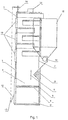
- the automatic boiler according to the proposed technical solution comprises a double-walled housing 1, which forms a water jacket 2, a comb-shaped heat exchanger 3, which is made of two or more layers, a combustion chamber 4 with a cooling surface 5, a sighting device 6 and a butterfly valve 7, a grate 8, a device 9 for ash loosening with an electric motor 10, an ashes fall space 11, an ash trap door 12 which is connected by a chain 13 with a lever of a temperature controller 14, and a bunker 15, a feed screw 16 with an electric motor 17, a Fire extinguishing device consisting of a nozzle 18 with a water tank and a pump (not shown), viewing doors 19 and an electronic control unit 20 with a display surface.
- the electronic control unit has electrical couplings with indicator and signaling devices, as well as sensors for monitoring the flame guidance during fuel combustion, the draft and the overload of the electric motors and the water temperature in the boiler.
- the automatic boiler works as follows: Prior to commissioning, if biofuel is used in the form of pellets, granules or fines, the bunker 15 is charged with the selected fuel.
- the fire extinguishing container (not shown) is filled with water.
- a butterfly valve 7 is removed from the combustion chamber 4.
- the operating temperature of the boiler is set according to the required water temperature. Thereafter, the introduced into the combustion chamber 4 part of the fuel is ignited by means of a torch.
- the boiler starts operating in the selected mode.
- a feed screw 16 is rotated by an electric motor 17 which conveys fuel into the combustion chamber 4 at regular intervals, depending on the selected operating mode.
- the fuel slips down the inclined surface of the sighting device 6 and ignites when it comes to the grate 8.
- the sighting device 6 distributes the biofuel fed into the combustion chamber 4 by the feed screw 16 uniformly on the surface of the grate 8 and also serves to deflect the flame in the direction of the cooling surface 5.
- the multi-layer heat exchangers 3 whose layers are each comb-shaped in the lower part.
- Such an embodiment of the heat exchanger 3 ensures the formation of a maximum heat exchange surface with small dimensions of the boiler.
- the design of the heat exchangers 3, which are comb-shaped and multi-layered, also makes it possible to form thin heat transfer layers, which contributes to an accelerated heat release hot streams of combustion gases to the heat carrier and an accelerated heat transfer circulation within the boiler. As a result, this has the effect that the heat transfer medium is generally heated quickly.
- the cavities of the heat exchanger 3 are connected to the cavity of the water jacket 2 of the boiler housing 1. As a result, the operating temperature of the boiler is reached in a short time.
- An electronic control unit 20 monitors the flame guidance by means of sensors for monitoring the flame guidance in the fuel combustion, the draft and the overload of the electric motors. In the occurrence of malfunctions and deviations from predetermined parameters, the electronic control unit 20 interrupts the operation of the boiler. If the flame in the combustion chamber 4 of the boiler becomes too large and goes beyond the sighting device 6 and the fuel in the feed screw 16 flares up, the electronic control unit 20 issues a corresponding command to ignite the fuel in the bunker 15 excluded. As a result, the fire extinguishing device responds. The flame is extinguished in the auger from the water, which is fed from the fire extinguisher through the pipe to a nozzle 18.
- the boiler is switched to the operation with solid fuel.
- the cooling surface 5 is removed from the combustion chamber 4, and the butterfly valve 7 is mounted in front of the feed screw 16 in order to exclude the advance of the flame from the combustion chamber 4 into the bunker 15.
- the introduced into the combustion chamber 4 part of the fuel is ignited by means of a torch.
- the electronic control unit 20 monitors the operating state of the boiler based on sensors and controls the combustion process in the furnace.
- the ash trap door 12 is opened or closed by means of a chain 13 connected to the lever of the temperature controller 14, whereby continuous fuel combustion is maintained.
- the electronic control unit 20 ensures the automatic operation of the boiler.
- a corresponding type of charging the combustion chamber 4 is selected, which makes it possible to ensure a continuous fuel combustion in the furnace of the boiler.
- the electronic control unit 20 In case of deviations from the specified operating modes of the boiler, in the absence of flame in the furnace, lack of draft, water boiling, in the jamming of the electric motors and in the emergence of fire hazard, the electronic control unit 20, the operation of the boiler, which informed of a special indicator , Even in emergencies, in which a flame is created or penetrates into the cavity of the feed screw 16, switches the elektronisehe Control unit 20 to the fire extinguishing device to exclude the ignition of the fuel outside of the combustion chamber 4. The water supplied from the fire extinguisher through the duct of the nozzle 18 extinguishes the flame and at the same time stops the operation of the boiler.
- the electronic control unit 20 allows the reconnection of the boiler only after the elimination of causes of failure, malfunction or incidents.
- Visible doors 19 provide access to the combustion gas removal channel while performing routine and maintenance work on the boiler to clean surfaces of the heat exchangers 3 of soot deposits.
Landscapes
- Engineering & Computer Science (AREA)
- Mechanical Engineering (AREA)
- General Engineering & Computer Science (AREA)
- Chemical & Material Sciences (AREA)
- Combustion & Propulsion (AREA)
- Physics & Mathematics (AREA)
- Thermal Sciences (AREA)
- Steam Or Hot-Water Central Heating Systems (AREA)
- Solid-Fuel Combustion (AREA)
Applications Claiming Priority (2)
| Application Number | Priority Date | Filing Date | Title |
|---|---|---|---|
| MDS20160091A MD1128Z (ro) | 2016-07-25 | 2016-07-25 | Cazan de încălzire |
| PCT/MD2017/000004 WO2018021902A1 (fr) | 2016-07-25 | 2017-06-14 | Chaudière de chauffage |
Publications (2)
| Publication Number | Publication Date |
|---|---|
| EP3489582A1 true EP3489582A1 (fr) | 2019-05-29 |
| EP3489582A4 EP3489582A4 (fr) | 2019-07-10 |
Family
ID=58185194
Family Applications (1)
| Application Number | Title | Priority Date | Filing Date |
|---|---|---|---|
| EP17834839.7A Withdrawn EP3489582A4 (fr) | 2016-07-25 | 2017-06-14 | Chaudière de chauffage |
Country Status (4)
| Country | Link |
|---|---|
| EP (1) | EP3489582A4 (fr) |
| EA (1) | EA201900063A1 (fr) |
| MD (1) | MD1128Z (fr) |
| WO (1) | WO2018021902A1 (fr) |
Cited By (1)
| Publication number | Priority date | Publication date | Assignee | Title |
|---|---|---|---|---|
| CN114963159A (zh) * | 2021-02-20 | 2022-08-30 | 马成果 | 一种复合燃烧炉床及对应的锅炉 |
Family Cites Families (19)
| Publication number | Priority date | Publication date | Assignee | Title |
|---|---|---|---|---|
| SU108572A1 (ru) * | 1953-12-17 | 1956-11-30 | Л.А. Кирмалов | Устройство автоматического регулирований теплового режима мазутной мартеновской печи |
| SU1015200A2 (ru) * | 1981-12-30 | 1983-04-30 | Центральный Научно-Исследовательский И Проектно-Экспериментальный Институт Инженерного Оборудования | Устройство дл приготовлени гор чей воды |
| DE19723107A1 (de) * | 1997-06-03 | 1998-12-10 | Wodtke Gmbh | Verfahren und Vorrichtung zur Verbrennung von Holzpellets oder anderer rieselfähiger fester Brennstoffe |
| MD1794F1 (ro) * | 2000-11-27 | 2001-11-30 | Serghei Procopiuc | Cazan de încălzit apă cu gaz |
| MD3757C2 (ro) * | 2002-10-02 | 2009-06-30 | Валерий СОКОЛОВ | Cazan de încălzit apă |
| MD2616C2 (ro) * | 2003-01-11 | 2005-07-31 | Ravelon-Prim, Общество С Ограниченной Ответственностью | Cazan de încălzire |
| CN2605474Y (zh) * | 2003-03-12 | 2004-03-03 | 高学武 | 节能环保常压热水锅炉 |
| MD3819C2 (ro) * | 2004-07-19 | 2009-07-31 | Валерий СОКОЛОВ | Cazan de încălzit (variante) |
| DE102006009335A1 (de) * | 2006-03-01 | 2007-09-06 | Viessmann Werke Gmbh & Co Kg | Heizkessel, insbesondere für Bio-Festbrennstoffe |
| RU64735U1 (ru) * | 2007-03-19 | 2007-07-10 | Владимир Сергеевич Зайцев | Топка |
| MD245Z (ro) * | 2007-04-12 | 2011-02-28 | Анатол БОЛДИШОР | Cazan de încălzit apă cu combustibil solid, lichid sau gazos |
| MD246Z (ro) * | 2007-04-13 | 2011-02-28 | Анатол БОЛДИШОР | Cazan de încălzit apă cu combustibil solid sau lichid |
| US8011329B2 (en) * | 2007-07-18 | 2011-09-06 | Hardy Willie J | Automatically controlled outdoor pelletized bio-fuel-burning hydronic heater |
| AT11433U1 (de) * | 2009-06-10 | 2010-10-15 | Guntamatic Heiztechnik Gmbh | Heizkessel für stückelige brennstoffe, insbesondere holzpellets |
| FR2947327B1 (fr) * | 2009-06-24 | 2012-12-07 | Supra | Systeme d'alimentation pour appareil de chauffage a combustible solide fragmente |
| RU2451239C2 (ru) * | 2010-07-20 | 2012-05-20 | Дмитрий Борисович Петров | Автоматизированный угольный котел |
| RU104668U1 (ru) * | 2010-11-16 | 2011-05-20 | Дмитрий Борисович Петров | Автоматизированный угольный котел |
| RU155426U1 (ru) * | 2015-06-17 | 2015-10-10 | Константин Альбертович Истомин | Устройство подачи пеллет в горелку котла |
| CN204739572U (zh) * | 2015-06-18 | 2015-11-04 | 北京暖适洁新型节能环保锅炉有限公司 | 一种全自动无烟生物质锅炉 |
-
2016
- 2016-07-25 MD MDS20160091A patent/MD1128Z/ro not_active IP Right Cessation
-
2017
- 2017-06-14 EA EA201900063A patent/EA201900063A1/ru unknown
- 2017-06-14 EP EP17834839.7A patent/EP3489582A4/fr not_active Withdrawn
- 2017-06-14 WO PCT/MD2017/000004 patent/WO2018021902A1/fr not_active Ceased
Cited By (1)
| Publication number | Priority date | Publication date | Assignee | Title |
|---|---|---|---|---|
| CN114963159A (zh) * | 2021-02-20 | 2022-08-30 | 马成果 | 一种复合燃烧炉床及对应的锅炉 |
Also Published As
| Publication number | Publication date |
|---|---|
| WO2018021902A1 (fr) | 2018-02-01 |
| MD1128Y (ro) | 2017-02-28 |
| EA201900063A1 (ru) | 2019-06-28 |
| MD1128Z (ro) | 2017-09-30 |
| EP3489582A4 (fr) | 2019-07-10 |
Similar Documents
| Publication | Publication Date | Title |
|---|---|---|
| DE4200721A1 (de) | Ofen fuer feste brennstoffe, insbesondere fuer pellets | |
| DE2534841A1 (de) | Feuerungsverfahren und feuerungsanlage | |
| DE2652522C2 (de) | Heizkessel | |
| EP0038962A1 (fr) | Dispositif pour la combustion de matières solides légères par un foyer à chargement continu | |
| EP1563227A2 (fr) | Poele-cheminee et son utilisation | |
| EP1411295B1 (fr) | Four ou petit appareil de combustion | |
| DE102004038968B3 (de) | Automatisch arbeitender Hackschnitzelbrenner zum Anbau an Zentralheizungskessel mit einer Kesselleistung von 4 - 25 KW | |
| DE19625203A1 (de) | Einrichtung zur Zuführung von Luft in einen Ofen für schüttfähige feste Brennstoffe, insbesondere für Holzpellets | |
| AT503043B1 (de) | Kipprost für biomassekessel | |
| DE2934721A1 (de) | Wechselbrandkessel. | |
| EP0882931B1 (fr) | Procédé et dispositif pour la combustion de boulettes de bois ou de combustibles solides s'écoulant librement | |
| DE102008022696A1 (de) | Feuerungseinrichtung mit einer Reinigungseinrichtung | |
| AT412306B (de) | Ofen zur befeuerung von festem brennstoff | |
| DE3732271C2 (fr) | ||
| DE19709173C1 (de) | Ofen zur Feuerung von festem Brennstoff | |
| DE660096C (de) | Gliederkessel mit mittlerem Fuellschacht und unterem Abbrand zur Verfeuerung minderwertiger Kohle | |
| DE102008063709A1 (de) | Flammrohrkessel mit mechanischer Rostfeuerung | |
| AT412305B (de) | Ofen zur befeuerung von festem brennstoff | |
| DE3229063C2 (de) | Vorrichtung zum Anzünden von Festbrennstoffen in einem für feste und flüssige oder gasförmige Brennstoffe ausgelegten Heizkessel | |
| DE1106910B (de) | Feuerung mit Walzenrost fuer feste Brennstoffe mit kontinuierlicher Brennstoffzufuhr | |
| DE3105660A1 (de) | Verfahren und vorrichtung zum zuenden und verbrennen von fliessfaehigen brennstoffen | |
| DE102015014340B3 (de) | Heizsystem | |
| DE47879C (de) | Feuerungsanlage für flüssige Brennstoffe | |
| DD219264A1 (de) | Verbrennungsluftzufuehrung bei feuerungen mit unterem abbrand | |
| DE678140C (de) | Kohlenstaubfeuerung |
Legal Events
| Date | Code | Title | Description |
|---|---|---|---|
| PUAI | Public reference made under article 153(3) epc to a published international application that has entered the european phase |
Free format text: ORIGINAL CODE: 0009012 |
|
| 17P | Request for examination filed |
Effective date: 20190225 |
|
| AK | Designated contracting states |
Kind code of ref document: A1 Designated state(s): AL AT BE BG CH CY CZ DE DK EE ES FI FR GB GR HR HU IE IS IT LI LT LU LV MC MK MT NL NO PL PT RO RS SE SI SK SM TR |
|
| AX | Request for extension of the european patent |
Extension state: BA ME |
|
| A4 | Supplementary search report drawn up and despatched |
Effective date: 20190612 |
|
| RIC1 | Information provided on ipc code assigned before grant |
Ipc: F23K 3/16 20060101ALI20190605BHEP Ipc: F23N 5/24 20060101ALI20190605BHEP Ipc: F23B 40/00 20060101AFI20190605BHEP Ipc: F24H 9/20 20060101ALI20190605BHEP Ipc: F24H 1/32 20060101ALI20190605BHEP Ipc: F23N 5/00 20060101ALI20190605BHEP Ipc: F28F 3/02 20060101ALI20190605BHEP Ipc: F23M 5/08 20060101ALI20190605BHEP Ipc: F24H 1/26 20060101ALI20190605BHEP Ipc: F24H 9/18 20060101ALI20190605BHEP Ipc: F24H 1/00 20060101ALI20190605BHEP Ipc: F24H 1/38 20060101ALI20190605BHEP |
|
| DAV | Request for validation of the european patent (deleted) | ||
| DAX | Request for extension of the european patent (deleted) | ||
| 17Q | First examination report despatched |
Effective date: 20200715 |
|
| STAA | Information on the status of an ep patent application or granted ep patent |
Free format text: STATUS: THE APPLICATION IS DEEMED TO BE WITHDRAWN |
|
| 18D | Application deemed to be withdrawn |
Effective date: 20200926 |