EP3489627A1 - Massstabsgetreue 3d-modellkonglomeration - Google Patents
Massstabsgetreue 3d-modellkonglomeration Download PDFInfo
- Publication number
- EP3489627A1 EP3489627A1 EP17203519.8A EP17203519A EP3489627A1 EP 3489627 A1 EP3489627 A1 EP 3489627A1 EP 17203519 A EP17203519 A EP 17203519A EP 3489627 A1 EP3489627 A1 EP 3489627A1
- Authority
- EP
- European Patent Office
- Prior art keywords
- visual
- image
- model
- partial
- line
- Prior art date
- Legal status (The legal status is an assumption and is not a legal conclusion. Google has not performed a legal analysis and makes no representation as to the accuracy of the status listed.)
- Granted
Links
Images


Classifications
-
- G—PHYSICS
- G01—MEASURING; TESTING
- G01C—MEASURING DISTANCES, LEVELS OR BEARINGS; SURVEYING; NAVIGATION; GYROSCOPIC INSTRUMENTS; PHOTOGRAMMETRY OR VIDEOGRAMMETRY
- G01C11/00—Photogrammetry or videogrammetry, e.g. stereogrammetry; Photographic surveying
- G01C11/04—Interpretation of pictures
- G01C11/30—Interpretation of pictures by triangulation
-
- G—PHYSICS
- G01—MEASURING; TESTING
- G01C—MEASURING DISTANCES, LEVELS OR BEARINGS; SURVEYING; NAVIGATION; GYROSCOPIC INSTRUMENTS; PHOTOGRAMMETRY OR VIDEOGRAMMETRY
- G01C11/00—Photogrammetry or videogrammetry, e.g. stereogrammetry; Photographic surveying
- G01C11/02—Picture taking arrangements specially adapted for photogrammetry or photographic surveying, e.g. controlling overlapping of pictures
-
- G—PHYSICS
- G06—COMPUTING OR CALCULATING; COUNTING
- G06T—IMAGE DATA PROCESSING OR GENERATION, IN GENERAL
- G06T7/00—Image analysis
- G06T7/97—Determining parameters from multiple pictures
-
- H—ELECTRICITY
- H04—ELECTRIC COMMUNICATION TECHNIQUE
- H04N—PICTORIAL COMMUNICATION, e.g. TELEVISION
- H04N23/00—Cameras or camera modules comprising electronic image sensors; Control thereof
- H04N23/60—Control of cameras or camera modules
- H04N23/62—Control of parameters via user interfaces
-
- G—PHYSICS
- G06—COMPUTING OR CALCULATING; COUNTING
- G06T—IMAGE DATA PROCESSING OR GENERATION, IN GENERAL
- G06T2207/00—Indexing scheme for image analysis or image enhancement
- G06T2207/10—Image acquisition modality
- G06T2207/10004—Still image; Photographic image
- G06T2207/10012—Stereo images
Definitions
- the present invention relates generally to a method and device for generating a true-to-size or 3D-model of a real world scene according to claim 1 or claim 13 and to corresponding auxiliary aids and computer-implementations according to the invention.
- Measurements of a real world 3D-scene such as e.g. a room, a hall, a building, an object, or parts thereof etc. are required for many purposes.
- many constructional measures, construction work tasks, construction site coordination, Building-Information-Management (BIM)-systems, installation work, furnishing, carpentering, etc. rely on measurements of already constructed portions, which are herein generally referred to as a 3D-scene.
- pocket rule, protractor, spirit level, plummet etc. are more and more replaced by electronic measurement devices like electronic distance meters, such as a DISTO, tilt sensors, laser liners, etc. there is still much labor in the actual reconstruction of a sufficiently accurate 3D-model of a 3D-scene which is suitable for construction work tasks.
- Simpler approaches for 3D-capturing like those used in computer gaming and entertainment environments, e.g. as a Kinect-device or as in US 8,587,583 , are not suitable for absolute measurements of high accuracy, in such a way as it is required for construction work which often requires an accuracy of about 1 cm or preferably even below.
- 3D-captures of such entertainment-devices are not dimension accurate (which is also not at all required for their intended purpose anyway), those are not capable to derive a true-to-size or dimensionally stable 3D-model of a scene as desired in the present scope of construction work.
- Part of the object can also be that measurement accuracy does not suffer from the fact that multiple different recordings are required to capture the whole 3D-scene.
- such a surveying or measurement system for 3D-scenes - although actually deriving a 3D-model of the scene - is based on 2D-pictures and 2D-views presented to the operator.
- the craftsman is, mostly intuitively, taking a picture of each of the walls of a room (or a sequence of multiple successive pictures of a wall if this wall does not fit completely within the field of view (FOV) of a single picture). Intuitively, he will almost always try to capture a small portion of a corner of the wall at the edge of the image.
- FOV field of view
- such a surveying or measurement system for 3D-scenes has to comprehend and to cope with the users intuitive behavior and to provide him with a solution which is intuitive for the human mind, even for an untrained operator.
- a simple approach would be to actually provide the user only with a limited portion of the real field of view which is actually captured by the hardware system, in such a way that there is actually a sufficient overlap of the captured pictures, even if the user-chosen overlap in the limited view which was provided to the user would be insufficient - but such is not the main core of the present invention.
- those objects can be solved by providing a device and/or method for a three dimensional surveying of a 3D-scene for deriving a true-to-size 3D-model.
- This involves deriving a first 3D-partial-model of a section of the 3D-scene together with a capturing of at least one corresponding first 2D-visual-image. Since this does not cover the whole of the desired 3D-scene it also involves deriving a second 3D-partial-model of another section of the 3D-scene, together with a capturing of at least one therewith corresponding second 2D-visual-image.
- the first 3D-partial-model is then conglomerated with the second 3D-partial-model to form the 3D-model of the 3D-scene, which is done with a defining of a first line segment in the first 2D-visual-image and of a second line segment in the second 2D-visual-image, which first and second line segments are representing a visual feature in the 2D-visual-images, preferably a visual feature which is common in both of the 2D-visual images or which line segments are having a defined geometric relation or constraint in-between the 2D visual images.
- the first and second line segments in the 2D-visual-images are utilized in conglomerating or combining of the corresponding 3D-partial models to form the 3D-model of the whole 3D-scene. For example by applying geometric restrictions in the conglomeration, like e.g. fixating one or more degrees of freedom in the conglomeration.
- the conglomeration according to the invention is done with the aid of line segments which are defined by means of the 2D-visual images, not directly in the 3D-partial-models themselves.
- the invention relates to a method for a three dimensional measuring or surveying of a 3D-scene for deriving a true-to-size 3D-model of the 3D-scene.
- the 3D-model is therefore dimensionally stable, so it is a 3D-model of which dimensional measurements can be taken, for example scaled dimensional and/or angular measurements of the 3D-model with an accuracy of at least a few centimeters, preferably a few millimeters or even below.
- the 3D-scene can in particular be embodied as an indoor scene, like a room, a hall, etc. as a field of view restriction discussed above is then dominating, but the invention can optionally also be applied to an outdoor scene.
- the method comprises deriving a first 3D-partial-model of an, in particular incomplete, section of the 3D-scene, which deriving comprises a capturing of at least one first 2D-visual-image, which first 2D-visual-image is corresponding to the first 3D- partial-model.
- the method also comprises a deriving of a second 3D-partial-model of an, in particular another incomplete, section of the 3D-scene, which deriving comprises a capturing of at least one second 2D-visual-image, which second 2D-visual-image is corresponding, complying or correlating to the second 3D-partial-model.
- the second 3D-partial-model is different from the first 3D-partial-model, e.g. it can be from a different point of view and/or with a different direction of view.
- the first and the second 3D-partial-models are therein at least partially overlapping, in many instances only overlapping in a small portion, like below 30%, below 20% or below 10% of their fields of view.
- the method then comprises a conglomerating or combining of the first 3D-partial-model with the second 3D-partial-model to form the 3D-model of the whole 3D-scene which is desired to be measured.
- this is done with a defining of a first line segment in the first 2D-visual-image and a defining of a second line segment in the second 2D-visual-image.
- the first and second line segments are representing a visual feature or sections of visual features in the 2D-visual images.
- the visual feature is a visual feature which is common in both of the first and second 2D-visual-image, in particular wherein the first and the second line segment at least partially coincide or overlap at the same visual feature, e.g.
- the visual feature can also define a defined geometric constraint other than being the same visual feature, like e.g. being orthogonal, parallel, in a defined angle, in the same plane, etc.
- the thereby defined one or more first and second line segment within each of the first and second 2D-visual-images are the exploited or utilized in the conglomerating or combining of the corresponding first 3D-partial model with the second 3D-partial model to form the 3D-model of the 3D-scene, for example by thereby providing a geometric restrictions for the conglomerating of the 3D-partial models, defined by means of the line sections in the first and second 2D-visual images.
- first line segment in the first camera picture, a first line segment is defined and in the second camera picture a second line segment is defined, wherein the first and the second line segment are sections of a visible line feature, such as e.g. an edge- or corner-feature, which is common in both of the pictures.
- first and the second line segment can at least partially coincide or overlap.
- first and the second line segment can also just relate to the same visual feature or to features which at least have a known geometrical relation to one another.
- the method can e.g. also additionally comprise that:
- a group of two or more interconnected first or second line segments can be defined.
- a template of a geometric feature or a construction work feature which is comprised in the 2D-visual image in particular a template of known geometrical feature, preferably with defined geometric properties like parallels, right, angles, being in level, etc. like ,e.g. a door, a window, a table, a corner, a baseboard, etc.
- the defining of the first or second line segment can be done with a graphically overlaying of a graphical line symbol on the 2D-visual-image.
- Such can in particular comprise a providing of controls and/or handles for aligning the line symbol on the 2D-visual-image by user interaction.
- the first and/or second line segment can comprise at least two handles, which are movable within the 2D-visual-image, for bringing said line segment into congruence with e.g. an edge- or line-feature within the 2D-visual image.
- the marking of a line segment can not only be done by providing handles, but can alternatively or additionally also be done by drawing or dragging a line with a pen or a finger on a touch sensitive display, by mouse, by a contact-free input means, etc.
- there can be different types of feature markings which can be provided in the 2D-visual image by the user or with user-interactions.
- Those types of features can correspond to geometric features given in the image, wherein the different types can correspond to one or more degrees of freedom, which are defined and by this type of feature and which can be used as references in conglomerating the 3D-partial models.
- the types of features can be illustrated in the visual image (or optionally also in a 3D view) by specific symbols which represent those features. For example:
- Those types of features can therein e.g. be selected from a menu, or they can be dragged from a side-bar to the corresponding location within the image.
- gesture recognition of a touch (or non-contact) input system can be used to distinct different types of features. For example, tapping can define a point, dragging can define a line, a (at least approximate) circling can refer to a plane (or for defining a normal vector for the plane), etc.
- the system can also provide an automatic or semi-automatic detection of potential geometric features in the captures 2D and/or 3D data. Besides a fully automated attempt, a preferred option can provide an interactive suggestion of features derived by numerical processing to the 2D-images and/or 3D data for detecting the features, such as a machine learned detector, an image processing algorithm, an edge detection, etc.
- Another embodiment according to the invention can comprise a marking (e.g. by tapping on a touch screen) a section of the 2D-image, for which section and its vicinity the system is then executing an automatically analyzing for detecting potential geometric features like edges, corners, a plane, etc. followed by a providing of a proposal of a geometric feature at the tapped location, e.g. by an according indication on a screen showing the 2D-image.
- a marking e.g. by tapping on a touch screen
- a section of the 2D-image for which section and its vicinity the system is then executing an automatically analyzing for detecting potential geometric features like edges, corners, a plane, etc. followed by a providing of a proposal of a geometric feature at the tapped location, e.g. by an according indication on a screen showing the 2D-image.
- the method can also comprise an automatic snapping of the first or second line segment to a visual image feature such as an edge- or corner feature in the 2D-visual-image.
- the edge- or corner feature can be derived by an automatic pattern recognition unit.
- an automatic fine snapping can be derived with a sub-pixel resolution of the 2D-picture, e.g. when the defining comprises an automatic identifying of a potential candidate for the at least one visual feature for aligning one of the line segments by an artificial intelligence computing unit or the like.
- There can be an automated fine-snapping of the at least one line section to such an automatically identified 2D-visual-image feature e.g.
- line segments can be derived in sub-pixel accuracy from the 2D-images by edge-extraction and/or line-fitting algorithms.
- the snapping can also be applied in the 3D-partial model, for example comprising a selecting or marking of a feature in the 2D-image, but with a snapping to a geometric feature in the 3D-partial model.
- a geometric feature in the 3D-partial model can be e.g. a line segment derived by a plane fitting and intersecting of two planes, a point by plane fitting and intersection of two planes, etc.
- the first and the second line segments can also be assigned to a therewith corresponding feature in a virtual plan view, such as a floor plan, map or the like.
- a virtual plan view such as a floor plan, map or the like.
- This can comprise an additional defining of the line segments, as those are defined in the 2D-images, in a pre-given 2D or 3D digital floor plan of the 3D-scene.
- the digital floor plan can therein be only approximate or not to scale, for example only defining the shape, but not the dimensions of the room.
- a floor plan is also kind of a virtually generated 2D-image, the same principles as for the 2D-visual-images can be applied.
- such a floor plan can comprise geometric restrictions of the defined line segment, like angular dependencies in-between the line segments.
- the first or second line segment can be provided with a defined angular constraint (or other geometric relation) with respect to an additional line segment, point or plane.
- a constraint can define a perpendicularity or a parallelism.
- such an angular constraint can, preferably automatically, be derived from the virtual plan view.
- a point of view and/or direction of view for the deriving the first 3D-partial-model can differ from the one for the deriving the second 3D-partial-model, which means the capturing device can be moved around in the 3D-scene at random and it is not demanded to have a substantially single point of view as usual for taking panorama-pictures.
- the second line section can optionally also be automatically defined within the second 2D-visual-image, by automatically identifying analogous features within both of the 2D-visual-images by a numeric image processing unit.
- a capturing of the 3D-partial-models can be established by a stereo-camera, a triangulation or structured light arrangement, wherein the corresponding 2D-visual-image is captured by a camera of said stereo-camera, triangulation or structured light arrangement.
- the deriving of the first 3D-partial-model can be done by stereo-2D-imaging from at least two different points of view, resulting in a stereo-pair of 2D-visual-images as base, whereof the 3D-partial-model is derived, and wherein at least one of those stereo-pair 2D-visual-images is used in defining the at least one line segment.
- the invention can be embodied as a surveying device for carrying out the method described herein, which at least comprises a 3D-sensor for deriving the 3D-partial-models and a 2D-visual-image-sensor for deriving the 2D-visual-images.
- a 3D-sensor for deriving the 3D-partial-models
- a 2D-visual-image-sensor for deriving the 2D-visual-images.
- the device also comprises a 2D visual display for providing the 2D-visual-images with a touch screen for defining the line segments, and a numerical processing unit with a conglomerator for calculating the conglomerating of the 3D-partial-models based on the defined line segments, e.g. embodied in a computer chip.
- the device can for example comprise at least two 2D-imaging cameras arranged in a stereo-basis with respect to each other. Those can be used for a stereoscopic 3D-partial-models deriving as well as for the 2D-visual-image capturing according to the invention.
- the device can comprises at least one 2D-imaging camera and at least one 3D-point-cloud or range image measuring unit, in particular a RIM-camera-sensor, a structured light 3D-sensor or a triangulation sensor.
- the method, or at least those parts of it which involve computation and/or calculation, can also be embodied as one or more computer program products which are stored on a machine readable medium or embodied as electromagnetic wave (such as e.g. a wired or wireless data signal). Consequently, the invention further relates to such a computer program product comprising program code for a 3D-true to size 3D-modeling according to the invention.
- the computer program product is configured for executing a method as described above, in particular with a providing of an interface for a defining of line segments in 2D-visual-images and computing the thereby resulting geometric restrictions in a combination of multiple corresponding 3D-partial-models to form a conglomerated 3D-model.
- such a program code which is configured for deriving a true-to-size 3D-model of a 3D-scene can comprises an acquiring of a first digital 3D-partial-model of a section of the 3D-scene, e.g. by reading 3D-data from a 3D-sensor-unit, which comprises at least one first digital 2D-visual-image, e.g. by reading picture data from a digital camera unit.
- an acquiring of a second digital 3D-partial-model of a section of the 3D-scene, which comprises at least one second digital 2D-visual-image is comprised.
- the according 3D-partial model can be derived by a programmed stereo-imaging analysis on at least two images each of which is taken by a corresponding digital camera that is arranged in a stereo-basis with respect to the other.
- at least one of the at least two images can be the 2D-visual-image taken together with the corresponding 3D-partial-model.
- the computer program is then configured to execute a numerically conglomerating the first 3D-partial-model with the second 3D-partial-model to form the 3D-model of the 3D-scene.
- Such is programmed to be done with utilizing a first line segment defined in the first 2D-visual-image and also a second line segment defined in the second 2D-visual-image.
- Those line segments are representing a same visual feature in each of the first and second 2D-visual-image and can be provided to the computer program, e.g. by an operators input.
- the line segments can in particular be utilized as a geometrical restriction in the numerically conglomerating of the 3D-partial models.
- the computer program can be executed in a device, which device therefore also involves a computation means built to run a computer program providing the functionality according to the invention, with or without the computer program actually loaded.
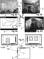
- FIG. 1a An example of an embodiment of the present invention is illustrated in Fig. 1a, Fig. 1b and Fig. 2 .
- FIG. 1a illustrates an exemplary first 2D-visual-image 1a, overlaid by some first line-segments 2a,2b,2c. Also shown is a non-mandatory viewing-grid 3.
- Such a first 2D-visual-image 1a is taken by a measuring or surveying device, in particular by a device according to the present invention.
- the 2D-visual image can be embodied as one image of stereoscopic view which is used to derive the 3D-partial model.
- the 2D-visual-image 1a can be taken by a kind of camera-system, comprising a, preferably digital, image sensor and an optical system with lenses and/or other optical components.
- the camera-system can therein preferably be calibrated as known in the art to compensate for geometric- and/or optical- distortions, color- and/or intensity- deviations, etc., e.g. by an evaluation of a defined reference pattern.
- the 3D-scene to be surveyed by the device is the inside of a briefing room, which is planned to be modernized by some construction work.
- the craftsman is therefore taking a device for measuring the room - which represents the 3D-scene to be surveyed - in order to derive a 3D-model 4 of the room which is true to size (or in other words dimensionally stable).
- measurements for construction work will then be planned and/or executed.
- the 3D-model 4 is required to be dimensionally accurate in the order of at least about a cm or preferably in the mm magnitude.
- the 3D-model 4 is not explicitly shown due to lack of a reasonably comprehensible presentability.
- the device captures a 3D-model 4a by an according 3D-sensor-unit.
- the 3D-sensor unit is preferably working optically in the visible and/or invisible spectral range and can e.g. be implemented based on stereoscopic principles, triangulation or deflectometry, like stereoscopic pictures, light-section, structured light, pattern and stripe projection measurements, SLAM-calculations, etc., or based on time-of-flight or phase-based distance measurement, like a RIM-camera, an electronic distance meter, or the like, alone or in combination. Also scanningtype 3D-sensors are known.
- first field of view comprises a first wall of the room and the second field of view comprises a second wall of the room.
- a craftsman will in general intuitively consider to capture such, or similar views, when given the task to measure or survey the room.
- the present invention now combines those first and second 3D-partial-models 4a,4b with a specific approach to result in the 3D-model 4 of the whole 3D-scene which has to be measured.
- One aspect of the present invention is that an ordinary user - such as an on-site craftsman and not a highly skilled 3D-design-engineer trained on 3D-CAD systems - in general has difficulties to handle 3D-models on their own.
- the present invention therefore proposes not to provide the operator with the multiple 3D-partial-models 4a,4b at fist hand, but instead to take and provide simpler 2D-visual-images 1a,1b to the operator, which 2D-visual-images were taken for this purpose upon capturing the corresponding 3D-partial-models 4a,4b.
- the operator handles the 2D-visual-images 1a,1b. He is thereby enabled to aid or enable the conglomerating or combining of the 3D-partial-models 4a,4b to a complete 3D-scene-model without being required to actually interact with the 3D-partial-models 4a,4b themselves or directly.
- At least one line segment 2 within the 2D-visual-image 1a e.g. indicated by specifically embodiments 2a,2b,2c,... of such line segments 2) being graphically overlaid to the 2D-visual-image 1a shown to the operator.
- Such a line segment 2 is provided as a first line segment 2b in the first 2D-visual-image 1a and as a second line segment 2b in the second 2D-visual-image 1b.
- the image-corresponding first 3D-partial-model 4a and second 3D-partial-model 4b are conglomerated to form the 3D-model 4 of the full 3D-scene.
- Fig. 2 Such a conglomerating is tried to be shown in Fig. 2 .- illustrating the walls from Fig. 1a and Fig. 1b combined to a 3D-model-view of the corner-scene of the room, using information on the line segments 2a,2b,2c in the 2D-visual images 1a and 1b.
- the line segments 2b and 2c each present in at least a first and a second 2D-Visual image 1a,1b are used to result in the 3D-model 4 according to the invention.
- the approach according to the invention establishes an accurate reference of the 3D-partial-models, providing a true to size 3D-model in their combination, which in particular can fulfill the accuracy requirements for construction work.
- Another not mandatory option which is shown in this embodiment is a definition of a geometric restriction in-between a first and second line section 2c, here given by the example of an angular restriction 5 of a 90° angular arrangement.
- Other examples of restrictions 5 will be discussed in the following.
- Fig. 3a illustrates some exemplary embodiment of such line segments 2a,2b,2c according to the invention in an abstracted view of a 3D-scene, depicted in the 2D-visual image 1.
- a line segment 2a in the 2D-visual-image of the 3D-scene which is located at the edge between the floor and the wall.
- the lines segment 2a indicates this edge and is located somewhere along this edge where convenient, but in this embodiment it is not having a defined start- and/or endpoint - also known as a straight in geometry. It can for example be considered to indicate the direction of this edge in the 2D-image respectively in the corresponding 3D-partial model.
- the line segment 2b at the top-left corner of the room has a defined start-point (or end-point depending on the definition), which is here shown to be right in the corner of the room.
- the line segment 2b also indicates the direction of the edge between wall and ceiling.
- this line segment 2b can also be described as a vector, defined by its starting point and its direction, although its length and endpoint needs not to be defined - also known as ray in geometry.
- Such a start point can be in the corner of the room, but can optionally also be any defined point along this edge, e.g. at any identifiable item or marking along the edge.
- the line segment 2c to the right is a line segment which is characterized by a defined starting point and a defined endpoint - also known as line in geometry. For example defined by specific points at the top and bottom room corner, and thereby defining the vertical room corner.
- line segments 2a,2b,... defined and/or drawn, as it is (per definition) not actually possible to drawn an infinite line or the like.
- the line-segment 2a,2b,... can also represent a geometric feature which in fact defines such an (infinite) line without actually defined endpoints, or a vector or the like.
- endpoints or corner points in the picture (optionally even with handles for manipulating them), but not using them as endpoints for the geometric feature they are representing.
- endpoints or corner points in the picture (optionally even with handles for manipulating them), but not using them as endpoints for the geometric feature they are representing.
- the present invention can additionally also comprise information about a single point 6a, which can be exactly defined by a visual feature in the first and in the second 2D-visual-image 1a, 1b.
- a visual feature in the first and in the second 2D-visual-image 1a, 1b can be exactly defined by a visual feature in the first and in the second 2D-visual-image 1a, 1b.
- exemplary shown is a corner of the room, but it can also be another visually prominent fixed point 6a.
- the present invention can additionally also comprise information about a plane or flat surface in the 2D-visual-image 1a,1b, as indicated by the symbol 6b.
- features like a line, a plane or the like need not to be exactly at the same location but can be provided at a different locations at/along the feature which is represented by them.
- a flat floor can for example be defined substantially anywhere on the floor, in particular also in different pictures 1 at a different locations on that same floor.
- an edge or corner can be marked at different locations along this corner or edge to define a same line or direction for the conglomerating of the corresponding 3D-partial models.
- one or more of such line segments 2, optionally supplemented by points 6a or planes 6b, are provided in the first 2D-visual image 1a of the first field of view as well as in the second 2D-visual image 1b of the second field of view.
- the geometrical information gained thereby is utilized to conglomerate the respective corresponding first 3D-partial-model 4a and second 3D-partial model 4b to form a 3D-model 4 of the scene.
- the invention can thereby for example overcome a problem of having an overlap of the 3D-partial-models, which is too low to achieve an accurate 3D-conglomeration of the 3D-partial-models to form the whole scene with sufficient accuracy and certainty, which in cases of a low overlap can not be achieved automatically and on its own by a pure 3D-point-cloud-matching or the like.
- a lower overlap can e.g. be advantageous as less captures are required, which saves time and memory.
- an IMU or tilt sensor in the device can be used to automatically indicate substantially horizontal and/or vertical directions within the 2D-visual images 1a,b and/or 3D-partial models 4a,4b.
- FIG. 3b Some examples of embodiments are shown in Fig. 3b, Fig. 3c and Fig. 3d .
- a 3D-modeling based on two different 3D-partial models 4a,4b which are overlapping in their field of view in only a very small portion is shown in Fig. 3b .
- the view in the left illustrates a first 2D-visual-image 1a taken together with the first 3D-partial-model 4a in first view of a first part of the 3D-scene.
- the view in the right illustrates a second 2D-visual-image 1b taken together with the first 3D-partial-model 4b in a second view of a second part of the 3D-scene which is desired to be measured.
- first pair of line sections 2a comprising a first line section 2a defined in the first 2D-visual-image 1a and a corresponding second line section 2a in the second 2D visual picture 1b shown, which are corresponding in such a way that both of those are representing the same corner of the 3D-scene.
- Those line segments 2a can, but are not required to have a defined start or endpoint.
- Such defined start and/or endpoints are in particular provided in pairs (or triplets, etc. if provided in more than two images) which are referring to a same real world point in the according 2D-visual images, e.g. the same corner point of a room.
- the pairing can be auto-detected by the system according to plausibility calculations.
- Another option would be a pairing provided by the user, either by explicitly pairing the points (etc.) or according to a logical sequence in which the points (etc.) are defined one after the other.
- Such a pairing can e.g. be marked by different colors, labeling, indexing, etc. of the corresponding symbols shown overlaid or augmented to the 2D-images.
- each of the lines segments 2a can be located somewhere along this same corner-feature in each of the 2D-visual pictures 1a,1b.
- a second pair of line sections 2b comprising a third line section 2b defined in the first 2D-visual-image 1a and a corresponding fourth line section 2b in the second 2D visual picture 1b shown, which are located at the top corner of the room.
- there can be an automatic matching of pairs of the line features 2a,2b in-between the first and second 2D-visual image e.g.
- the system according to the present invention can resolve those pair-matching automatically or semi-automatically by presenting one or more calculated reasonable suggestions to the operator for verification.
- the pair-matching can be provided by the operator.
- a pair of single points 6a defined, comprising a first point 6a in the first 2D-visual-image 1a and a corresponding second point 6a in the second 2D visual picture 1b.
- a pair of plane surfaces 6b defined, comprising a first surface 6b in the first 2D-visual-image 1a and a corresponding second surface 6b in the second 2D visual picture 1b.
- Such corresponding surfaces can be the same surface, wherein their definition can comprise common surface points, or different totally points of the same surface.
- Another option according to the invention can comprise a first surface 6b and a second surface 6b, which are not actually the same surface but which are provided together with a geometric constraint, e.g. as being parallel (like a floor and a tabletop) or orthogonal (like a floor and a wall or like two different walls)- see also below.
- the number of such pairs of line sections 2, endpoints 2a, points 6a and planes 6b can vary within the common objectives that the sum of those are provided in such a way that the 3D-partial-models 4a,4b can be preferably unambiguously combined by the aid of those.
- one of such a pair can bring a restriction of definition in one or more degrees of freedom in the combination of the 3D-partial-models 4a,4b.
- those pairs are arranged and configured in such a way that those result in an unambiguously combination of the 3D-partial-models 4a,4b.
- redundancy can be deliberately introduced in order to increase accuracy, e.g. by some kind of known averaging or statistical approach.
- FIG. 3c illustrates yet another exemplary embodiment, in which line sections 2a that are indicating the same visual room corner feature are defined in each of a first and a second 2D-visual-pictures 1a,1b of a room taken from different viewing positions, each facing a different wall of the room.
- line sections 2b shown, which are not indicating the same corner features but which are paired by a restriction 5a according to which those two line sections 2b are in a 90° angular offset with respect to one another.
- Another restriction could be e.g. that the line sections 2b are in the same plane, which is the floor-plane, and optionally also that this plane - and therefore also the line sections 2b - are horizontal.
- Fig. 3d illustrates an example of an embodiment according to the invention, where the line sections 2t are not only straight, but comprising multiple line sections.
- the line sections 2t are not only straight, but comprising multiple line sections.
- the pair-of-edges-template 2t shown, which is placed in each room corner in the 2D-visual picture 1a and 1b.
- the pair-of-edges-template 2t can therein optionally also comprise the geometric restriction 5 that it has an offset of 90° in the different 2D-visual-images 1a, 1b.
- handles 7 provided, by which the pair-of-edges-template 2t can be adapted to the 2D-visual-images 1a,1b, as discussed below.
- Fig. 4a, Fig. 4b and Fig. 4c are illustrating another example of 2D-visual-images 2a,2b,2c of a scene to be 3D-modeled.
- the 3D-scene of which a 3D-model 4 is derived according to the invention comprises more than two different 2D-visual-images 1a,1b,1c and corresponding 3D-partial-models 4a,4b,4c, e.g. in form of depth-images, cloud-points, etc.
- there are the shown line-sections 2a,2b,2c and/or thereto linked geometric restrictions 5 are provided in each of the 2D-visual images 1a,1b,1c.
- the line-sections 2a,2b,2c are shown to be embodied as directional vectors, whereof some can be referenced to each other, e.g. by the shown angular restrictions, like the shown bows for 180° or 90° arrangements.
- Other such restrictions can be that some of the vectors are substantially the same vector in different visual images 1a,1b,1c, or that they have substantially the same direction, respectively are substantial parallel or coaxial, like by matching them in pairs (or triplets, etc.) e.g. by specific colors, or that they are in the same (floor-) plane, or that they are establishing a horizontal or vertical reference, etc.
- those line-sections 2a,2b,2c and/or geometric restrictions 5 can be provided by a human operator, preferably at least partially assisted by an automatic detection unit according to the invention as discussed below.
- an embodiment of the invention can present results in form of line sections (and optionally also points or faces) which are derived by the automatic detection unit, as suggestions to the operator, who verifies, corrects or dismisses those suggestions.
- the detection unit can therein comprise image processing means for deriving and/or identifying image features such as e.g. edges, corners, lines, intersections, etc., preferably in sub-pixel resolution of the 2D-visual-image.
- the operator can manually define the line-sections 2 in the 2D-visual-image according to the invention, preferably aided by the automated image processing features like e.g. an automatic snapping function for snapping an line-section 2, handle 7, point 6a, face 6b, etc.
- Fig. 5a and Fig. 5b there are two abstracted 2D-visual-images 1 of a corner symbolized. There are three line-segments 2a,2b,2c in each, which share a common intersection point at the corner.
- a semi-automatic approach can e.g. be embodied in such a way that an operator pre-selects a certain portion or adjacency in the 2D-visual-image 1 in which the automatic function will then be used. By doing so, e.g.
- a line section 2 in the shown case a ray-type line section with a defined starting point at the corner-intersection point, can be overlaid, preferably graphically overlaid by an illustration of the line section in the 2D-visual-image 1 which is provided to the operator.
- a first line 2a section in a first 2D-visual-image 1a is therein automatically and/or manually linked and/or geometrically restricted 5a to the same or another line section 2a,2b,2c,6a in the second visual image 1b.
- the corresponding 3D-partial models 4a,4b can be linked to form a single 3D-model 4 of a compound scene, in particular by applying thereof the resulting geometric links and restrictions in the 3D-partial-models 4a,4b.
- Fig. 6a and Fig. 6b are showing a similar embodiment as above, but herein at least one of the line segments 2am in the first 2D-visual-image 1a is set manually, by manipulating handles 7 of the line section 2a in the 2D visual image view, one moved to the intersection point and the other being one random point along the edge.
- Such can e.g. also be advantageous when portions of the edge are obstructed by items and not visible, whereby automatic detection is complicated.
- Such can e.g. also comprise an automatic snapping to an image detected visual edge feature.
- the intersection point 6am is manually corrected.
- the line segment 2c in the 2D-visual-image got the geometric restriction 5a applied, according to which it is substantially perpendicular to the line sections 2a and 2b.
- Fig. 7a and Fig. 7b the view is similar to above, but the line sections 2am,2bm,2cm were set by the operator by placing handles 7 on the visual edges in the 2D-visual images 1a and 1b.
- the intersection 6a was found automatically and provided as suggested additional point for conglomerating the visual 3D-images.
- FIG. 8a to Fig. 8d there is another embodiment of the surveying of a true-to-size 3D-model according to the invention illustrated.
- Fig. 8a as well as Fig. 8b are showing 2D-visual-images, in which line sections 2 are overlaid, by which the corresponding 3D-partial models are conglomerated to a 3D-model 4 as illustrated in Fig. 8d .
- the 2D-visual-images are overlaid by some first line-segments 2a,2b,2c as well as by some elucidations to aid the description of the invention - like the texts next to the line-segments, the heading, etc. - which are not necessarily mandatory to be shown in practical embodiments.
- plan 9 or floor-plan of the 3D-scene provided, as symbolized in the 3D view of a floor plan 9 in Fig. 8c .
- It can e.g. be a rough sketch or predefined, non-full-scale template, such as e.g. a cubical room-template or the like.
- the plan-template 9 according to the invention can therein in particular be used to provide geometrical restrictions 5 in way which is intuitive to the operator without having to bother with numerical values or symbols, but to be applied visually in 2D screen view.
- the line segments 2 can therein be matched to corresponding plan features 2p and 2h of the plan 9.
- the feature 2p can be an Edge 2 as defined in the images at Fig. 8a and Fig. 8b and the feature 2h can be a height reference or horizontal reference 2 as indicated in those images.
- FIG. 10 Another option which is here shown, but which could also be considered independently of the 3D-plan-view is a 2D-view 10 in which information regarding the field of view of the device can be graphically defined and provided, in particular as additional information for the conglomeration of the 3D-partial models 4a,4b, whereby additional geometric restriction for the combination of the 3D-partial-models 4a,4b can be derived which aid the process of combining them in a true to size manner.
- the (at least roughly) indicated marking 10v refers to a selected wall of the floor-plan 10 and/or 9, which indicates the wall which shown in the picture 1b of Fig.
- the indication 10v can easily be done by the operator, but can also be at least partially assisted or automated by technical aids like a compass, a level sensor, an accelerometer, a gyroscope, an IMU or the like.
- FIG. 9 there is a similar embodiment comprising an additional plan view 9 in the provision of the line segments 2a,2b,2c, besides the 2D-visual-images 1a and 1b.
- the there shown 2D-floor-plan-view 9 can therein define geometric relations and/or restrictions to be - at least approximately met by the line sections 2a,2b,2c and accordingly by the corresponding 3D-partial-models 4a,4b, which are actually to be combined in a dimensionally accurate manner.
- the floor plan 9 can an approximate template, part of a CAD-plan of the scene to be measured or e.g. also be generated (and exactly measured) by the same device, using an incorporated point to point measurement by an accurate DISTO-functionality.
- Fig. 10a an exemplary embodiment of a device 20 according to the invention is shown.
- the shown example device 20 is embodied to be handheld by an operator during use, in particular in view of size and weight.
- the handheld device 20 can optionally also comprise a coupling element 29 to be attached to a kind of tripod or stick to keep it more still during the measurements.
- the device 20 preferably comprises a 2D visual display 28 for providing the operator with the 2D-visual-images, line sections and other measurement relevant information, but can optionally also be linked to an external display unit, computer or tablet, either wired or wireless.
- the display 28 can be a touch-screen and/or the device 20 can comprise dedicated buttons 27.
- the device 20 at least comprises a 2D-visual-image-sensor 22a,22b,22c or 2D-visual-imaging-camera (such as a CCD- or CMOS-camera) for deriving the 2D-visual-images.
- a 2D-visual-image-sensor 22a,22b,22c or 2D-visual-imaging-camera (such as a CCD- or CMOS-camera) for deriving the 2D-visual-images.
- there are two cameras 22a and 22b here shown with optional light sources 26a,26b or flashlights.
- Those cameras can be digital RGB-cameras and are arranges in a stereo-basis, whereby those can not only take the 2D-pictures, but can also be used in combination as 3D-sensor operating on the stereo imaging principle to derive a 3D partial model, which can be derived on basis of images from both of the cameras and their fixed stereo-basis distance.
- the device 20 can also comprise one or more light sources 26a,26b, e.g. embodying flashlights for taking 2D pictures in low light environments.
- a dedicated 3D-measurement-sensor 21 (which is not mandatory in the shown stereo imaging approach with cameras 22a and 22b), for deriving the 3D-partial models (such as e.g. a RIM-camera, a structured light sensor, a triangulation sensor, etc.).
- a dedicated 3D-measurement-sensor 21 is present and it comprises an internal 2D visual imaging functionality (as e.g. often the case for RIM-cameras, etc)
- the cameras 22a and 22b can be not mandatory, but at least one of them is still an option, e.g. for taking higher quality 2D visual images.
- Another embodiment can also comprise one or more cameras 22a,22b and a 3D-measurement-sensor 21 as well.
- Fig. 10b a first exemplary embodiment of a block diagram of a device 20 according to the invention is shown.
- the 3D-sensor-block 21 configured for determining a 3D-measurement information 4 of its field of view (e.g. in form of a depth-image), which is herein also referenced as 3D-partial-model 4.
- the 3D-sensor-block 21 of this embodiment therefore comprises at least two 2D-image-sensor-blocks 22 in known arrangement, configured for deriving 2D-visual-images 1 their corresponding fields of view.
- the images from those 2D cameras 22a,22b are processed to derive a 3D model of their fields of view.
- cameras 22a and 22b can be cameras of stereoscopic-view 3D-sensor 21.
- the device comprises a computation unit 25, such as a microprocessor or a similar electronic device, which is configured to provide the calculations for the method according to the invention, in particular computing the 2D-visual-images 1 and the 3D-partial-models 4 as well as the line sections 2 according to the invention, e.g. by a stored computer program.
- the computation unit can therein comprises a conglomerator 23, which is calculating a combination of multiple 3D-partial models 4a,4b which were taken with different views comprising different portions of the 3D-scene which has to be recorded, to form a true to size combined 3D-model.
- the different views can in particular point in different directions and/or being taken from different locations, preferably with the views being overlapping by at least a small portion.
- the 2D-images and the 3D-model for each of those views are in a known reference to each other, in particular as the 3D-model had been derived from those images, whereby a known corresponding of geometric features in the 2D-image and in the corresponding 3D-partial model can be established.
- the combination of the corresponding 3D-partial models can be established, e.g. for resolving 3D-geometric ambiguities in one or more dimensions based on restrictions defined by the line-segments 2 in the 2D-visual-images 1.
- a second exemplary embodiment of a block diagram of a device 20 according to the invention comprises a 3D-sensor-block 21 configured for determining a 3D-measurement information 4 of its field of view, e.g. in form of a depth-image, point-cloud, etc. which is herein also referenced as 3D-partial-model 4.
- the 3D-sensor-block 21 can e.g. be embodied as a RIM-camera, (in particular based on the time of flight measurement principle, a structured light 3D-sensor, a triangulation sensor, a laser stripe sensor or another 3D-sensor.
- the device also comprises at least one 2D-image-sensor-block 22, configured for deriving 2D-visual-images 1 of its field of view.
- the fields of view of the sensors 21 and 22 are therein overlapping, at least partially but preferably substantially.
- the 2D-camera 22 can not only be standalone as indicated by 22c, but can also be a functional part of the 3D-sensor 21, which part (22) is capable of taking visual 2D-images 1, as e.g. indicated (22).
- camera (22) can be an inherent 2D-imaging functionality of the 3D-sensor 21, like a capability of taking 2D-RGB-pictures.
- the 2D-imaging functionality for taking the 2D images according to the invention can also be provided by a separate camera 22c, which has a defined arrangement and field of view with respect to the 3D-sensor 21.
- the device comprises a computation unit 25, such as a microprocessor or a similar electronic device, which is configured to provide the calculations for the method according to the invention, in particular computing the 2D-visual-images 1 and the 3D-partial-models 4 as well as the line sections 2 according to the invention, e.g. by a stored computer program.
- the computation unit can therein comprises a conglomerator 23, which is calculating a combination of multiple 3D-partial models 4a,4b to form a true to size combined 3D-model, according to the invention by involving the line segments 2a for the same visual or geometrical features in the combining calculations, e.g. for resolving 3D-geometric ambiguities in one or more dimensions based on restrictions defined by the line-segments 2 in the 2D-visual-images 1.
- a conglomerator 23 is calculating a combination of multiple 3D-partial models 4a,4b to form a true to size combined 3D-model, according to the invention by involving the line segments 2a for the same visual or geometrical features in the combining calculations, e.g. for resolving 3D-geometric ambiguities in one or more dimensions based on restrictions defined by the line-segments 2 in the 2D-visual-images 1.
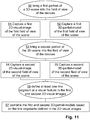
- the method for measuring a true-to-size 3D-model according to the invention can therein be embodied comprising the steps as shown in the example of a basic block diagram of Fig. 11 .
- a first portion of a 3D-scene which has to be captured is brought into the field of view of the device 20, for example a wall of a room or at least part of the wall.
- the viewing direction can be chosen to be substantially perpendicular to the wall - although not strictly required according to the invention, most operators will intuitively do so.
- a capturing of a first 2D-visual-image 1a of the first field of view of the scene is done, for example by an ordinary 2D-digital-camera at the device 20.
- a capturing of a first 3D-partial-model 4a of the first field of view of the scene is done, preferably substantially at the same time as the 2D-visual-image 1a is taken, e.g. by an optical 3D-capturing-unit, like a stereographic camera, a range imaging (RIM) camera, a time of flight (TOF) camera, a structured light measurement, a triangulation measurement, light sectioning, etc.
- an optical 3D-capturing-unit like a stereographic camera, a range imaging (RIM) camera, a time of flight (TOF) camera, a structured light measurement, a triangulation measurement, light sectioning, etc.
- a second portion of the 3D-scene is brought into the field of view of the device 20, for example by relocating and/or reorienting the device.
- a capturing of a second 2D-visual-image 1b of the second field of view of the scene is established.
- a capturing of a second 3D-partial-model 4b of the second field of view of the scene is done, e.g. in the same way as the first one.
- a defining of at least one line segment 2a at a visual feature in the first and in the second 2D-visual-images 1a,1b is done, which can be done automatically, semi-automatically or manually by an operator.
- a combining or conglomerating of the first and second 3D-partial-models 4a,4b is established based on the line segments 2a defined within the 2D-visual-images 1, e.g. by applying geometrical restrictions resulting from defined pairs of line segments 2a in-between the first and second 2D-images and their respective relations.
Landscapes
- Engineering & Computer Science (AREA)
- Physics & Mathematics (AREA)
- General Physics & Mathematics (AREA)
- Multimedia (AREA)
- Radar, Positioning & Navigation (AREA)
- Remote Sensing (AREA)
- Computer Vision & Pattern Recognition (AREA)
- Theoretical Computer Science (AREA)
- Human Computer Interaction (AREA)
- Signal Processing (AREA)
- Processing Or Creating Images (AREA)
Priority Applications (3)
| Application Number | Priority Date | Filing Date | Title |
|---|---|---|---|
| EP17203519.8A EP3489627B1 (de) | 2017-11-24 | 2017-11-24 | Massstabsgetreue 3d-modellkonglomeration |
| US16/197,029 US11015930B2 (en) | 2017-11-24 | 2018-11-20 | Method for 2D picture based conglomeration in 3D surveying |
| CN201811406728.9A CN109840950B (zh) | 2017-11-24 | 2018-11-23 | 得到真实尺寸3d模型的方法、勘测装置 |
Applications Claiming Priority (1)
| Application Number | Priority Date | Filing Date | Title |
|---|---|---|---|
| EP17203519.8A EP3489627B1 (de) | 2017-11-24 | 2017-11-24 | Massstabsgetreue 3d-modellkonglomeration |
Publications (2)
| Publication Number | Publication Date |
|---|---|
| EP3489627A1 true EP3489627A1 (de) | 2019-05-29 |
| EP3489627B1 EP3489627B1 (de) | 2020-08-19 |
Family
ID=60452516
Family Applications (1)
| Application Number | Title | Priority Date | Filing Date |
|---|---|---|---|
| EP17203519.8A Active EP3489627B1 (de) | 2017-11-24 | 2017-11-24 | Massstabsgetreue 3d-modellkonglomeration |
Country Status (3)
| Country | Link |
|---|---|
| US (1) | US11015930B2 (de) |
| EP (1) | EP3489627B1 (de) |
| CN (1) | CN109840950B (de) |
Cited By (4)
| Publication number | Priority date | Publication date | Assignee | Title |
|---|---|---|---|---|
| GB2574795A (en) * | 2018-05-04 | 2019-12-25 | Signaturize Holdings Ltd | Generating virtual representations |
| US20210374978A1 (en) * | 2020-05-29 | 2021-12-02 | Faro Technologies, Inc. | Capturing environmental scans using anchor objects for registration |
| GB2606067A (en) * | 2018-05-04 | 2022-10-26 | Signaturize Holdings Ltd | Generating virtual representations |
| EP4130648A4 (de) * | 2020-03-24 | 2023-09-06 | Panasonic Intellectual Property Management Co., Ltd. | Dimensionsmessverfahren und dimensionsmessvorrichtung |
Families Citing this family (7)
| Publication number | Priority date | Publication date | Assignee | Title |
|---|---|---|---|---|
| US10552981B2 (en) * | 2017-01-16 | 2020-02-04 | Shapetrace Inc. | Depth camera 3D pose estimation using 3D CAD models |
| WO2019205069A1 (en) * | 2018-04-27 | 2019-10-31 | Beijing Didi Infinity Technology And Development Co., Ltd. | Systems and methods for updating 3d model of building |
| US12014120B2 (en) | 2019-08-28 | 2024-06-18 | MFTB Holdco, Inc. | Automated tools for generating mapping information for buildings |
| US11243656B2 (en) * | 2019-08-28 | 2022-02-08 | Zillow, Inc. | Automated tools for generating mapping information for buildings |
| WO2022025869A1 (en) * | 2020-07-28 | 2022-02-03 | Hewlett-Packard Development Company, L.P. | Deriving metrology data for an object based on abstract geometry data |
| CN116547493A (zh) * | 2020-12-08 | 2023-08-04 | 松下知识产权经营株式会社 | 三维模型生成方法及三维模型生成装置 |
| US11683462B2 (en) * | 2021-06-04 | 2023-06-20 | Dierks Technology, Inc. | Matching segments of video for virtual display of a space |
Citations (10)
| Publication number | Priority date | Publication date | Assignee | Title |
|---|---|---|---|---|
| US5432712A (en) * | 1990-05-29 | 1995-07-11 | Axiom Innovation Limited | Machine vision stereo matching |
| US20050089213A1 (en) * | 2003-10-23 | 2005-04-28 | Geng Z. J. | Method and apparatus for three-dimensional modeling via an image mosaic system |
| EP2051102A1 (de) | 2007-10-18 | 2009-04-22 | Leica Geosystems AG | Justierbares elektro-optisches Messgerät |
| US7568289B2 (en) | 2005-03-14 | 2009-08-04 | Robert Bosch Company Limited | Handheld optical distance measurement device |
| US20120188559A1 (en) | 2009-07-22 | 2012-07-26 | Faro Technologies, Inc. | Device for optically scanning and measuring an environment |
| WO2013033787A1 (en) * | 2011-09-07 | 2013-03-14 | Commonwealth Scientific And Industrial Research Organisation | System and method for three-dimensional surface imaging |
| US8587583B2 (en) | 2011-01-31 | 2013-11-19 | Microsoft Corporation | Three-dimensional environment reconstruction |
| WO2014060562A1 (en) * | 2012-10-17 | 2014-04-24 | Cathx Research Ltd | Improvements in relation to underwater imaging for underwater surveys |
| WO2016065063A1 (en) * | 2014-10-22 | 2016-04-28 | Pointivo, Inc. | Photogrammetric methods and devices related thereto |
| US9752863B2 (en) | 2011-05-13 | 2017-09-05 | Hexagon Technology Center Gmbh | Calibration method for a device having a scan function |
Family Cites Families (8)
| Publication number | Priority date | Publication date | Assignee | Title |
|---|---|---|---|---|
| US6333749B1 (en) * | 1998-04-17 | 2001-12-25 | Adobe Systems, Inc. | Method and apparatus for image assisted modeling of three-dimensional scenes |
| US8933925B2 (en) * | 2009-06-15 | 2015-01-13 | Microsoft Corporation | Piecewise planar reconstruction of three-dimensional scenes |
| EP2502208A2 (de) * | 2009-11-19 | 2012-09-26 | Ocali Bilisim Teknolojileri Yazilim Donanim San. Tic. A.S. | Direktes 3-d-zeichnen mit kameraansichtseinschränkungen |
| US9142022B2 (en) * | 2013-10-11 | 2015-09-22 | Intel Corporation | 3D object tracking |
| CN106463032B (zh) * | 2014-03-03 | 2019-05-31 | Vsk电子有限公司 | 利用方向感应的入侵检测方法及系统 |
| US10636184B2 (en) * | 2015-10-14 | 2020-04-28 | Fovia, Inc. | Methods and systems for interactive 3D segmentation |
| US9965863B2 (en) * | 2016-08-26 | 2018-05-08 | Elekta, Inc. | System and methods for image segmentation using convolutional neural network |
| CN106898048B (zh) * | 2017-01-19 | 2019-10-29 | 大连理工大学 | 一种可适应复杂场景的无畸变集成成像三维显示方法 |
-
2017
- 2017-11-24 EP EP17203519.8A patent/EP3489627B1/de active Active
-
2018
- 2018-11-20 US US16/197,029 patent/US11015930B2/en active Active
- 2018-11-23 CN CN201811406728.9A patent/CN109840950B/zh active Active
Patent Citations (10)
| Publication number | Priority date | Publication date | Assignee | Title |
|---|---|---|---|---|
| US5432712A (en) * | 1990-05-29 | 1995-07-11 | Axiom Innovation Limited | Machine vision stereo matching |
| US20050089213A1 (en) * | 2003-10-23 | 2005-04-28 | Geng Z. J. | Method and apparatus for three-dimensional modeling via an image mosaic system |
| US7568289B2 (en) | 2005-03-14 | 2009-08-04 | Robert Bosch Company Limited | Handheld optical distance measurement device |
| EP2051102A1 (de) | 2007-10-18 | 2009-04-22 | Leica Geosystems AG | Justierbares elektro-optisches Messgerät |
| US20120188559A1 (en) | 2009-07-22 | 2012-07-26 | Faro Technologies, Inc. | Device for optically scanning and measuring an environment |
| US8587583B2 (en) | 2011-01-31 | 2013-11-19 | Microsoft Corporation | Three-dimensional environment reconstruction |
| US9752863B2 (en) | 2011-05-13 | 2017-09-05 | Hexagon Technology Center Gmbh | Calibration method for a device having a scan function |
| WO2013033787A1 (en) * | 2011-09-07 | 2013-03-14 | Commonwealth Scientific And Industrial Research Organisation | System and method for three-dimensional surface imaging |
| WO2014060562A1 (en) * | 2012-10-17 | 2014-04-24 | Cathx Research Ltd | Improvements in relation to underwater imaging for underwater surveys |
| WO2016065063A1 (en) * | 2014-10-22 | 2016-04-28 | Pointivo, Inc. | Photogrammetric methods and devices related thereto |
Cited By (8)
| Publication number | Priority date | Publication date | Assignee | Title |
|---|---|---|---|---|
| GB2574795A (en) * | 2018-05-04 | 2019-12-25 | Signaturize Holdings Ltd | Generating virtual representations |
| US10991161B2 (en) | 2018-05-04 | 2021-04-27 | Signaturize Holdings Ltd | Generating virtual representations |
| GB2574795B (en) * | 2018-05-04 | 2022-10-05 | Signaturize Holdings Ltd | Generating virtual representations |
| GB2606067A (en) * | 2018-05-04 | 2022-10-26 | Signaturize Holdings Ltd | Generating virtual representations |
| GB2606067B (en) * | 2018-05-04 | 2023-02-15 | Signaturize Holdings Ltd | Generating virtual representations |
| US11816799B2 (en) | 2018-05-04 | 2023-11-14 | Signaturize Holdings Ltd | Generating virtual representations |
| EP4130648A4 (de) * | 2020-03-24 | 2023-09-06 | Panasonic Intellectual Property Management Co., Ltd. | Dimensionsmessverfahren und dimensionsmessvorrichtung |
| US20210374978A1 (en) * | 2020-05-29 | 2021-12-02 | Faro Technologies, Inc. | Capturing environmental scans using anchor objects for registration |
Also Published As
| Publication number | Publication date |
|---|---|
| EP3489627B1 (de) | 2020-08-19 |
| CN109840950B (zh) | 2023-02-28 |
| CN109840950A (zh) | 2019-06-04 |
| US20190162534A1 (en) | 2019-05-30 |
| US11015930B2 (en) | 2021-05-25 |
Similar Documents
| Publication | Publication Date | Title |
|---|---|---|
| US11015930B2 (en) | Method for 2D picture based conglomeration in 3D surveying | |
| US9747392B2 (en) | System and method for generation of a room model | |
| US10977857B2 (en) | Apparatus and method of three-dimensional reverse modeling of building structure by using photographic images | |
| US9888215B2 (en) | Indoor scene capture system | |
| EP3063553B1 (de) | System und verfahren zur messung mittels lasersweeps | |
| JP4537557B2 (ja) | 情報呈示システム | |
| KR101973917B1 (ko) | 3차원 계측 장치 및 그 계측 지원 처리 방법 | |
| JP6642968B2 (ja) | 情報処理装置、情報処理方法、プログラム | |
| US9667955B2 (en) | Method of calibrating a camera | |
| JP6636042B2 (ja) | 床の処理方法 | |
| US20150317070A1 (en) | Mobile handheld instruments and methods | |
| JP7420135B2 (ja) | 情報処理装置、情報処理方法、及びプログラム | |
| US20180184070A1 (en) | Method and system for depth estimation based upon object magnification | |
| CN104662435A (zh) | 确定与用于捕获至少一个图像的捕获装置关联的装置的位置和方向的方法 | |
| JP2009278456A (ja) | 映像表示装置 | |
| CN103999125B (zh) | 三维测量方法和机器人设备 | |
| JP2007212187A (ja) | ステレオ写真計測装置、ステレオ写真計測方法、及びステレオ写真計測プログラム | |
| US20180293751A1 (en) | Measuring apparatus and corresponding measuring method | |
| CN109816712B (zh) | 基于图像的边缘测量 | |
| Cheng et al. | AR-based positioning for mobile devices | |
| JP2020139742A (ja) | 画像計測システム及び画像計測方法 | |
| JP6448413B2 (ja) | 屋根勾配推定システム及び屋根勾配推定方法 | |
| KR102127978B1 (ko) | 구조도 생성 방법 및 장치 | |
| JP7743784B2 (ja) | 拡張現実表示装置、方法、及びプログラム | |
| KR101695727B1 (ko) | 스테레오 비전을 이용한 위치검출 시스템 및 위치검출 방법 |
Legal Events
| Date | Code | Title | Description |
|---|---|---|---|
| PUAI | Public reference made under article 153(3) epc to a published international application that has entered the european phase |
Free format text: ORIGINAL CODE: 0009012 |
|
| STAA | Information on the status of an ep patent application or granted ep patent |
Free format text: STATUS: THE APPLICATION HAS BEEN PUBLISHED |
|
| AK | Designated contracting states |
Kind code of ref document: A1 Designated state(s): AL AT BE BG CH CY CZ DE DK EE ES FI FR GB GR HR HU IE IS IT LI LT LU LV MC MK MT NL NO PL PT RO RS SE SI SK SM TR |
|
| AX | Request for extension of the european patent |
Extension state: BA ME |
|
| STAA | Information on the status of an ep patent application or granted ep patent |
Free format text: STATUS: REQUEST FOR EXAMINATION WAS MADE |
|
| 17P | Request for examination filed |
Effective date: 20191128 |
|
| RBV | Designated contracting states (corrected) |
Designated state(s): AL AT BE BG CH CY CZ DE DK EE ES FI FR GB GR HR HU IE IS IT LI LT LU LV MC MK MT NL NO PL PT RO RS SE SI SK SM TR |
|
| RIC1 | Information provided on ipc code assigned before grant |
Ipc: G01C 11/02 20060101AFI20191205BHEP |
|
| GRAP | Despatch of communication of intention to grant a patent |
Free format text: ORIGINAL CODE: EPIDOSNIGR1 |
|
| STAA | Information on the status of an ep patent application or granted ep patent |
Free format text: STATUS: GRANT OF PATENT IS INTENDED |
|
| INTG | Intention to grant announced |
Effective date: 20200317 |
|
| RIN1 | Information on inventor provided before grant (corrected) |
Inventor name: HELLER, TOBIAS Inventor name: WILTSCHE, SIEGFRIED Inventor name: METZLER, BERNHARD |
|
| GRAS | Grant fee paid |
Free format text: ORIGINAL CODE: EPIDOSNIGR3 |
|
| GRAA | (expected) grant |
Free format text: ORIGINAL CODE: 0009210 |
|
| STAA | Information on the status of an ep patent application or granted ep patent |
Free format text: STATUS: THE PATENT HAS BEEN GRANTED |
|
| AK | Designated contracting states |
Kind code of ref document: B1 Designated state(s): AL AT BE BG CH CY CZ DE DK EE ES FI FR GB GR HR HU IE IS IT LI LT LU LV MC MK MT NL NO PL PT RO RS SE SI SK SM TR |
|
| REG | Reference to a national code |
Ref country code: CH Ref legal event code: EP |
|
| REG | Reference to a national code |
Ref country code: DE Ref legal event code: R096 Ref document number: 602017021858 Country of ref document: DE |
|
| REG | Reference to a national code |
Ref country code: AT Ref legal event code: REF Ref document number: 1304433 Country of ref document: AT Kind code of ref document: T Effective date: 20200915 |
|
| REG | Reference to a national code |
Ref country code: IE Ref legal event code: FG4D |
|
| REG | Reference to a national code |
Ref country code: LT Ref legal event code: MG4D |
|
| REG | Reference to a national code |
Ref country code: NL Ref legal event code: MP Effective date: 20200819 |
|
| PG25 | Lapsed in a contracting state [announced via postgrant information from national office to epo] |
Ref country code: SE Free format text: LAPSE BECAUSE OF FAILURE TO SUBMIT A TRANSLATION OF THE DESCRIPTION OR TO PAY THE FEE WITHIN THE PRESCRIBED TIME-LIMIT Effective date: 20200819 Ref country code: LT Free format text: LAPSE BECAUSE OF FAILURE TO SUBMIT A TRANSLATION OF THE DESCRIPTION OR TO PAY THE FEE WITHIN THE PRESCRIBED TIME-LIMIT Effective date: 20200819 Ref country code: PT Free format text: LAPSE BECAUSE OF FAILURE TO SUBMIT A TRANSLATION OF THE DESCRIPTION OR TO PAY THE FEE WITHIN THE PRESCRIBED TIME-LIMIT Effective date: 20201221 Ref country code: HR Free format text: LAPSE BECAUSE OF FAILURE TO SUBMIT A TRANSLATION OF THE DESCRIPTION OR TO PAY THE FEE WITHIN THE PRESCRIBED TIME-LIMIT Effective date: 20200819 Ref country code: GR Free format text: LAPSE BECAUSE OF FAILURE TO SUBMIT A TRANSLATION OF THE DESCRIPTION OR TO PAY THE FEE WITHIN THE PRESCRIBED TIME-LIMIT Effective date: 20201120 Ref country code: FI Free format text: LAPSE BECAUSE OF FAILURE TO SUBMIT A TRANSLATION OF THE DESCRIPTION OR TO PAY THE FEE WITHIN THE PRESCRIBED TIME-LIMIT Effective date: 20200819 Ref country code: NO Free format text: LAPSE BECAUSE OF FAILURE TO SUBMIT A TRANSLATION OF THE DESCRIPTION OR TO PAY THE FEE WITHIN THE PRESCRIBED TIME-LIMIT Effective date: 20201119 Ref country code: BG Free format text: LAPSE BECAUSE OF FAILURE TO SUBMIT A TRANSLATION OF THE DESCRIPTION OR TO PAY THE FEE WITHIN THE PRESCRIBED TIME-LIMIT Effective date: 20201119 |
|
| REG | Reference to a national code |
Ref country code: AT Ref legal event code: MK05 Ref document number: 1304433 Country of ref document: AT Kind code of ref document: T Effective date: 20200819 |
|
| PG25 | Lapsed in a contracting state [announced via postgrant information from national office to epo] |
Ref country code: NL Free format text: LAPSE BECAUSE OF FAILURE TO SUBMIT A TRANSLATION OF THE DESCRIPTION OR TO PAY THE FEE WITHIN THE PRESCRIBED TIME-LIMIT Effective date: 20200819 Ref country code: RS Free format text: LAPSE BECAUSE OF FAILURE TO SUBMIT A TRANSLATION OF THE DESCRIPTION OR TO PAY THE FEE WITHIN THE PRESCRIBED TIME-LIMIT Effective date: 20200819 Ref country code: PL Free format text: LAPSE BECAUSE OF FAILURE TO SUBMIT A TRANSLATION OF THE DESCRIPTION OR TO PAY THE FEE WITHIN THE PRESCRIBED TIME-LIMIT Effective date: 20200819 Ref country code: LV Free format text: LAPSE BECAUSE OF FAILURE TO SUBMIT A TRANSLATION OF THE DESCRIPTION OR TO PAY THE FEE WITHIN THE PRESCRIBED TIME-LIMIT Effective date: 20200819 Ref country code: IS Free format text: LAPSE BECAUSE OF FAILURE TO SUBMIT A TRANSLATION OF THE DESCRIPTION OR TO PAY THE FEE WITHIN THE PRESCRIBED TIME-LIMIT Effective date: 20201219 |
|
| PG25 | Lapsed in a contracting state [announced via postgrant information from national office to epo] |
Ref country code: CZ Free format text: LAPSE BECAUSE OF FAILURE TO SUBMIT A TRANSLATION OF THE DESCRIPTION OR TO PAY THE FEE WITHIN THE PRESCRIBED TIME-LIMIT Effective date: 20200819 Ref country code: DK Free format text: LAPSE BECAUSE OF FAILURE TO SUBMIT A TRANSLATION OF THE DESCRIPTION OR TO PAY THE FEE WITHIN THE PRESCRIBED TIME-LIMIT Effective date: 20200819 Ref country code: RO Free format text: LAPSE BECAUSE OF FAILURE TO SUBMIT A TRANSLATION OF THE DESCRIPTION OR TO PAY THE FEE WITHIN THE PRESCRIBED TIME-LIMIT Effective date: 20200819 Ref country code: EE Free format text: LAPSE BECAUSE OF FAILURE TO SUBMIT A TRANSLATION OF THE DESCRIPTION OR TO PAY THE FEE WITHIN THE PRESCRIBED TIME-LIMIT Effective date: 20200819 Ref country code: SM Free format text: LAPSE BECAUSE OF FAILURE TO SUBMIT A TRANSLATION OF THE DESCRIPTION OR TO PAY THE FEE WITHIN THE PRESCRIBED TIME-LIMIT Effective date: 20200819 |
|
| REG | Reference to a national code |
Ref country code: DE Ref legal event code: R097 Ref document number: 602017021858 Country of ref document: DE |
|
| PG25 | Lapsed in a contracting state [announced via postgrant information from national office to epo] |
Ref country code: AT Free format text: LAPSE BECAUSE OF FAILURE TO SUBMIT A TRANSLATION OF THE DESCRIPTION OR TO PAY THE FEE WITHIN THE PRESCRIBED TIME-LIMIT Effective date: 20200819 Ref country code: AL Free format text: LAPSE BECAUSE OF FAILURE TO SUBMIT A TRANSLATION OF THE DESCRIPTION OR TO PAY THE FEE WITHIN THE PRESCRIBED TIME-LIMIT Effective date: 20200819 Ref country code: ES Free format text: LAPSE BECAUSE OF FAILURE TO SUBMIT A TRANSLATION OF THE DESCRIPTION OR TO PAY THE FEE WITHIN THE PRESCRIBED TIME-LIMIT Effective date: 20200819 |
|
| PLBE | No opposition filed within time limit |
Free format text: ORIGINAL CODE: 0009261 |
|
| STAA | Information on the status of an ep patent application or granted ep patent |
Free format text: STATUS: NO OPPOSITION FILED WITHIN TIME LIMIT |
|
| PG25 | Lapsed in a contracting state [announced via postgrant information from national office to epo] |
Ref country code: MC Free format text: LAPSE BECAUSE OF FAILURE TO SUBMIT A TRANSLATION OF THE DESCRIPTION OR TO PAY THE FEE WITHIN THE PRESCRIBED TIME-LIMIT Effective date: 20200819 Ref country code: SK Free format text: LAPSE BECAUSE OF FAILURE TO SUBMIT A TRANSLATION OF THE DESCRIPTION OR TO PAY THE FEE WITHIN THE PRESCRIBED TIME-LIMIT Effective date: 20200819 |
|
| REG | Reference to a national code |
Ref country code: CH Ref legal event code: PL |
|
| 26N | No opposition filed |
Effective date: 20210520 |
|
| PG25 | Lapsed in a contracting state [announced via postgrant information from national office to epo] |
Ref country code: LU Free format text: LAPSE BECAUSE OF NON-PAYMENT OF DUE FEES Effective date: 20201124 Ref country code: IT Free format text: LAPSE BECAUSE OF FAILURE TO SUBMIT A TRANSLATION OF THE DESCRIPTION OR TO PAY THE FEE WITHIN THE PRESCRIBED TIME-LIMIT Effective date: 20200819 |
|
| REG | Reference to a national code |
Ref country code: BE Ref legal event code: MM Effective date: 20201130 |
|
| PG25 | Lapsed in a contracting state [announced via postgrant information from national office to epo] |
Ref country code: CH Free format text: LAPSE BECAUSE OF NON-PAYMENT OF DUE FEES Effective date: 20201130 Ref country code: SI Free format text: LAPSE BECAUSE OF FAILURE TO SUBMIT A TRANSLATION OF THE DESCRIPTION OR TO PAY THE FEE WITHIN THE PRESCRIBED TIME-LIMIT Effective date: 20200819 Ref country code: LI Free format text: LAPSE BECAUSE OF NON-PAYMENT OF DUE FEES Effective date: 20201130 |
|
| PG25 | Lapsed in a contracting state [announced via postgrant information from national office to epo] |
Ref country code: IE Free format text: LAPSE BECAUSE OF NON-PAYMENT OF DUE FEES Effective date: 20201124 |
|
| PG25 | Lapsed in a contracting state [announced via postgrant information from national office to epo] |
Ref country code: TR Free format text: LAPSE BECAUSE OF FAILURE TO SUBMIT A TRANSLATION OF THE DESCRIPTION OR TO PAY THE FEE WITHIN THE PRESCRIBED TIME-LIMIT Effective date: 20200819 Ref country code: MT Free format text: LAPSE BECAUSE OF FAILURE TO SUBMIT A TRANSLATION OF THE DESCRIPTION OR TO PAY THE FEE WITHIN THE PRESCRIBED TIME-LIMIT Effective date: 20200819 Ref country code: CY Free format text: LAPSE BECAUSE OF FAILURE TO SUBMIT A TRANSLATION OF THE DESCRIPTION OR TO PAY THE FEE WITHIN THE PRESCRIBED TIME-LIMIT Effective date: 20200819 |
|
| PG25 | Lapsed in a contracting state [announced via postgrant information from national office to epo] |
Ref country code: MK Free format text: LAPSE BECAUSE OF FAILURE TO SUBMIT A TRANSLATION OF THE DESCRIPTION OR TO PAY THE FEE WITHIN THE PRESCRIBED TIME-LIMIT Effective date: 20200819 |
|
| PG25 | Lapsed in a contracting state [announced via postgrant information from national office to epo] |
Ref country code: BE Free format text: LAPSE BECAUSE OF NON-PAYMENT OF DUE FEES Effective date: 20201130 |
|
| PGFP | Annual fee paid to national office [announced via postgrant information from national office to epo] |
Ref country code: DE Payment date: 20251119 Year of fee payment: 9 |
|
| PGFP | Annual fee paid to national office [announced via postgrant information from national office to epo] |
Ref country code: GB Payment date: 20251121 Year of fee payment: 9 |
|
| PGFP | Annual fee paid to national office [announced via postgrant information from national office to epo] |
Ref country code: FR Payment date: 20251126 Year of fee payment: 9 |