EP3489736A1 - Anzeigevorrichtung mit einstellbarem betrachtungswinkel - Google Patents
Anzeigevorrichtung mit einstellbarem betrachtungswinkel Download PDFInfo
- Publication number
- EP3489736A1 EP3489736A1 EP17752687.8A EP17752687A EP3489736A1 EP 3489736 A1 EP3489736 A1 EP 3489736A1 EP 17752687 A EP17752687 A EP 17752687A EP 3489736 A1 EP3489736 A1 EP 3489736A1
- Authority
- EP
- European Patent Office
- Prior art keywords
- display device
- link
- viewing angle
- disposed
- angle according
- Prior art date
- Legal status (The legal status is an assumption and is not a legal conclusion. Google has not performed a legal analysis and makes no representation as to the accuracy of the status listed.)
- Withdrawn
Links
Images


Classifications
-
- F—MECHANICAL ENGINEERING; LIGHTING; HEATING; WEAPONS; BLASTING
- F16—ENGINEERING ELEMENTS AND UNITS; GENERAL MEASURES FOR PRODUCING AND MAINTAINING EFFECTIVE FUNCTIONING OF MACHINES OR INSTALLATIONS; THERMAL INSULATION IN GENERAL
- F16M—FRAMES, CASINGS OR BEDS OF ENGINES, MACHINES OR APPARATUS, NOT SPECIFIC TO ENGINES, MACHINES OR APPARATUS PROVIDED FOR ELSEWHERE; STANDS; SUPPORTS
- F16M11/00—Stands or trestles as supports for apparatus or articles placed thereon ; Stands for scientific apparatus such as gravitational force meters
- F16M11/02—Heads
- F16M11/04—Means for attachment of apparatus; Means allowing adjustment of the apparatus relatively to the stand
- F16M11/06—Means for attachment of apparatus; Means allowing adjustment of the apparatus relatively to the stand allowing pivoting
- F16M11/10—Means for attachment of apparatus; Means allowing adjustment of the apparatus relatively to the stand allowing pivoting around a horizontal axis
-
- H—ELECTRICITY
- H04—ELECTRIC COMMUNICATION TECHNIQUE
- H04N—PICTORIAL COMMUNICATION, e.g. TELEVISION
- H04N23/00—Cameras or camera modules comprising electronic image sensors; Control thereof
- H04N23/50—Constructional details
- H04N23/53—Constructional details of electronic viewfinders, e.g. rotatable or detachable
-
- A—HUMAN NECESSITIES
- A42—HEADWEAR
- A42B—HATS; HEAD COVERINGS
- A42B3/00—Helmets; Helmet covers ; Other protective head coverings
- A42B3/04—Parts, details or accessories of helmets
-
- F—MECHANICAL ENGINEERING; LIGHTING; HEATING; WEAPONS; BLASTING
- F16—ENGINEERING ELEMENTS AND UNITS; GENERAL MEASURES FOR PRODUCING AND MAINTAINING EFFECTIVE FUNCTIONING OF MACHINES OR INSTALLATIONS; THERMAL INSULATION IN GENERAL
- F16M—FRAMES, CASINGS OR BEDS OF ENGINES, MACHINES OR APPARATUS, NOT SPECIFIC TO ENGINES, MACHINES OR APPARATUS PROVIDED FOR ELSEWHERE; STANDS; SUPPORTS
- F16M13/00—Other supports for positioning apparatus or articles; Means for steadying hand-held apparatus or articles
- F16M13/04—Other supports for positioning apparatus or articles; Means for steadying hand-held apparatus or articles for supporting on, or holding steady relative to, a person, e.g. by chains, e.g. rifle butt or pistol grip supports, supports attached to the chest or head
-
- A—HUMAN NECESSITIES
- A42—HEADWEAR
- A42B—HATS; HEAD COVERINGS
- A42B3/00—Helmets; Helmet covers ; Other protective head coverings
- A42B3/04—Parts, details or accessories of helmets
- A42B3/30—Mounting radio sets or communication systems
-
- F—MECHANICAL ENGINEERING; LIGHTING; HEATING; WEAPONS; BLASTING
- F16—ENGINEERING ELEMENTS AND UNITS; GENERAL MEASURES FOR PRODUCING AND MAINTAINING EFFECTIVE FUNCTIONING OF MACHINES OR INSTALLATIONS; THERMAL INSULATION IN GENERAL
- F16M—FRAMES, CASINGS OR BEDS OF ENGINES, MACHINES OR APPARATUS, NOT SPECIFIC TO ENGINES, MACHINES OR APPARATUS PROVIDED FOR ELSEWHERE; STANDS; SUPPORTS
- F16M11/00—Stands or trestles as supports for apparatus or articles placed thereon ; Stands for scientific apparatus such as gravitational force meters
- F16M11/02—Heads
- F16M11/04—Means for attachment of apparatus; Means allowing adjustment of the apparatus relatively to the stand
- F16M11/06—Means for attachment of apparatus; Means allowing adjustment of the apparatus relatively to the stand allowing pivoting
- F16M11/12—Means for attachment of apparatus; Means allowing adjustment of the apparatus relatively to the stand allowing pivoting in more than one direction
- F16M11/121—Means for attachment of apparatus; Means allowing adjustment of the apparatus relatively to the stand allowing pivoting in more than one direction constituted of several dependent joints
-
- F—MECHANICAL ENGINEERING; LIGHTING; HEATING; WEAPONS; BLASTING
- F16—ENGINEERING ELEMENTS AND UNITS; GENERAL MEASURES FOR PRODUCING AND MAINTAINING EFFECTIVE FUNCTIONING OF MACHINES OR INSTALLATIONS; THERMAL INSULATION IN GENERAL
- F16M—FRAMES, CASINGS OR BEDS OF ENGINES, MACHINES OR APPARATUS, NOT SPECIFIC TO ENGINES, MACHINES OR APPARATUS PROVIDED FOR ELSEWHERE; STANDS; SUPPORTS
- F16M11/00—Stands or trestles as supports for apparatus or articles placed thereon ; Stands for scientific apparatus such as gravitational force meters
- F16M11/02—Heads
- F16M11/04—Means for attachment of apparatus; Means allowing adjustment of the apparatus relatively to the stand
- F16M11/06—Means for attachment of apparatus; Means allowing adjustment of the apparatus relatively to the stand allowing pivoting
- F16M11/12—Means for attachment of apparatus; Means allowing adjustment of the apparatus relatively to the stand allowing pivoting in more than one direction
- F16M11/14—Means for attachment of apparatus; Means allowing adjustment of the apparatus relatively to the stand allowing pivoting in more than one direction with ball-joint
-
- F—MECHANICAL ENGINEERING; LIGHTING; HEATING; WEAPONS; BLASTING
- F16—ENGINEERING ELEMENTS AND UNITS; GENERAL MEASURES FOR PRODUCING AND MAINTAINING EFFECTIVE FUNCTIONING OF MACHINES OR INSTALLATIONS; THERMAL INSULATION IN GENERAL
- F16M—FRAMES, CASINGS OR BEDS OF ENGINES, MACHINES OR APPARATUS, NOT SPECIFIC TO ENGINES, MACHINES OR APPARATUS PROVIDED FOR ELSEWHERE; STANDS; SUPPORTS
- F16M13/00—Other supports for positioning apparatus or articles; Means for steadying hand-held apparatus or articles
- F16M13/02—Other supports for positioning apparatus or articles; Means for steadying hand-held apparatus or articles for supporting on, or attaching to, an object, e.g. tree, gate, window-frame, cycle
-
- G—PHYSICS
- G02—OPTICS
- G02B—OPTICAL ELEMENTS, SYSTEMS OR APPARATUS
- G02B27/00—Optical systems or apparatus not provided for by any of the groups G02B1/00 - G02B26/00, G02B30/00
- G02B27/01—Head-up displays
-
- G—PHYSICS
- G02—OPTICS
- G02B—OPTICAL ELEMENTS, SYSTEMS OR APPARATUS
- G02B27/00—Optical systems or apparatus not provided for by any of the groups G02B1/00 - G02B26/00, G02B30/00
- G02B27/01—Head-up displays
- G02B27/017—Head mounted
- G02B27/0176—Head mounted characterised by mechanical features
-
- H—ELECTRICITY
- H04—ELECTRIC COMMUNICATION TECHNIQUE
- H04N—PICTORIAL COMMUNICATION, e.g. TELEVISION
- H04N23/00—Cameras or camera modules comprising electronic image sensors; Control thereof
- H04N23/50—Constructional details
- H04N23/54—Mounting of pick-up tubes, electronic image sensors, deviation or focusing coils
-
- A—HUMAN NECESSITIES
- A42—HEADWEAR
- A42B—HATS; HEAD COVERINGS
- A42B3/00—Helmets; Helmet covers ; Other protective head coverings
- A42B3/04—Parts, details or accessories of helmets
- A42B3/0406—Accessories for helmets
- A42B3/042—Optical devices
-
- F—MECHANICAL ENGINEERING; LIGHTING; HEATING; WEAPONS; BLASTING
- F16—ENGINEERING ELEMENTS AND UNITS; GENERAL MEASURES FOR PRODUCING AND MAINTAINING EFFECTIVE FUNCTIONING OF MACHINES OR INSTALLATIONS; THERMAL INSULATION IN GENERAL
- F16M—FRAMES, CASINGS OR BEDS OF ENGINES, MACHINES OR APPARATUS, NOT SPECIFIC TO ENGINES, MACHINES OR APPARATUS PROVIDED FOR ELSEWHERE; STANDS; SUPPORTS
- F16M2200/00—Details of stands or supports
- F16M2200/02—Locking means
- F16M2200/021—Locking means for rotational movement
- F16M2200/022—Locking means for rotational movement by friction
-
- G—PHYSICS
- G02—OPTICS
- G02B—OPTICAL ELEMENTS, SYSTEMS OR APPARATUS
- G02B27/00—Optical systems or apparatus not provided for by any of the groups G02B1/00 - G02B26/00, G02B30/00
- G02B27/01—Head-up displays
- G02B27/017—Head mounted
- G02B2027/0178—Eyeglass type
Definitions
- the present invention relates to a display device with adjustable viewing angle.
- the display module on the thermal image helmet or the headband is connected to the thermal image capturing device through the video data line between the thermal image helmets or the headbands with the display module.
- they are often connected by a serpentine tube or a hard-connected structure.
- serpentine tube there is a problem of easy aging of serpentine tube; in addition, after the use of the helmet, the serpentine tube has been adjusted, and even if subsequently adjusted for storage, the serpentine tube cannot be completely restored to the shape at the time of production, with the problem of no matching with the shape of the storage location of the box placed outside.
- the hard-connected structure adopted solves the problem of matching the shape of storage location of the externally placed box, its adjustment position is restricted, unable to adapt to the needs for adjusting the angles and orientations of different users; in addition, the weight of the hard-connected structure imposes burden on users.
- the thermal image device of the thermal image helmet or headband is often fixed on a helmet or headband by a mounting base, and its viewing angle is restricted by the wearing of the helmet.
- the display modules include liquid crystal screens, various viewfinders, and a variety of micro-projection displays discovered in recent years.
- a micro-projection display includes, for example, a micro-projection module and a prism, the micro-projection module is used to project an image to the prism, and human eyes can see the images by observing the prism.
- the present invention provides a display device with adjustable viewing angle.
- the present invention employs the following technical solutions.
- a display device with adjustable viewing angle comprising a base portion, one end of a multi-link mechanism is disposed on the base portion, and the other end is disposed with a display device.
- a first adjusting device is disposed between the multi-link mechanism and the base portion.
- a second adjusting device is disposed between the display module and the multi-link mechanism.
- the multi-link mechanism comprises a head link and a tail link, one end of the head link is disposed on the base portion by a first adjusting device, and the other end of the head link is movably connected to one end of the tail link, and the other end of the tail link is provided with the display device by a second adjusting device.
- the other end of the first adjusting device or the head link is connected to one end of the tail link by a hinge structure.
- the second adjusting device adopts a ball shaft structure.
- the ball shaft structure is a universal ball shaft structure.
- the head link is connected with the tail link through a link or a link group.
- a control button is disposed at the multi-link mechanism or at the display device.
- the device further comprises a thermal imager, and the base portion is disposed at the thermal imager.
- the device further comprises a spectacle frame, and the base portion is disposed at the spectacle frame.
- the base portion is provided with a snapping port.
- the base portion is connected to the thermal imager or the spectrum frame through a snap structure.
- the device further comprises an accommodating unit, and the base portion is disposed in the accommodating unit.
- the accommodating unit comprises an accommodating box, a baffle assembly disposed in the accommodating box, the baffle assembly comprises a top bead spring and a latching top bead disposed at the top of the top bead spring, and the multi-link mechanism cooperated therewith is provided with a card slot, and when accommodating, the latching top bead is snapped into the card slot.
- the accommodating unit further comprises a dialing component disposed on one side of the accommodating box, the dialing component comprises a dialing hand, a recovering spring, and a thimble, and the accommodating box is provided with a hole through which the thimble can pass, when dialing the dialing hand, the thimble passes through the hole of the accommodating box and then withstands the multi-link mechanism, so that the multi-link mechanism overcomes the elastic force of the latching top bead and then slides the latching top bead out of the card slot; after releasing the dialing hand, the recovering spring returns the dialing hand.
- the dialing component comprises a dialing hand, a recovering spring, and a thimble
- the accommodating box is provided with a hole through which the thimble can pass, when dialing the dialing hand, the thimble passes through the hole of the accommodating box and then withstands the multi-link mechanism, so that the multi-link mechanism overcomes the elastic force of the latching top bead and then slides the latching top
- a friction layer is provided on the surface of the tail link.
- a buffering component is disposed inside the accommodating unit.
- the device further comprises an accommodating groove, and the multi-link mechanism is accommodated in the accommodating groove.
- the accommodating unit is provided with a snap structure.
- the present invention can achieve the following beneficial effects.
- a multi-link mechanism the aging problem of the serpentine tube is solved by multi-link folding, and at the same time, the problem of matching with the storage location of the externally placed box can be adapted after use.
- the adjustment device with damping or the rear locking adjusting mechanism can position the display device in an easy-to-view adjustment position.
- the display device with adjustable viewing angle is added with a matching accommodating unit at the periphery, and the multi-link mechanism is used to accommodate the display device, playing a protective role.
- the accommodating unit is provided with a baffle assembly and a dialing component to fix and release the multi-link mechanism respectively.
- the display device of the present invention can be applied to various wearable devices. It can be used with various application devices such as measuring devices, sensing devices, communication devices such as wireless or wired communication devices, for example, a capturing device such as infrared or visible light device and other sensing devices, etc.
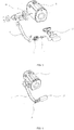
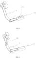
- a display device with an adjustable viewing angle comprises a base portion 19.
- One end of the multi-link mechanism is disposed on the base portion 19 by a first adjusting device, and the first adjusting device adopts a rotating shaft structure.
- an adjusting mechanism with damping is used, for example, a laterally disposed damped "-" shaped rotating shaft structure.
- the first adjusting device can be used to adjust the display device 13 up and down.
- a mounting cover is disposed on the outer side of the base portion 19, and the mounting cover wraps the "-" shaft structure.
- the other end of the multi-link mechanism is provided with a display device 13 as a display module through a second adjusting device 12.
- a micro-projection display device is adopted for convenient carrying and light weight design.
- the adjusting device can be an adjusting mechanism with a damping or rear locking adjusting mechanism, to position the display device in an easy-to-view adjusting position.
- the second adjusting device 12 is used to achieve fine adjustment of the angle of the display device 13, and preferably, the second adjusting device 12 employs an adjustment mechanism with damping, such as a universal ball shaft device with damping.
- a universal ball shaft device with a rotation limit can be used to avoid damage to the internal wires caused by excessive rotation.
- the video data cables of the display device 13 are placed inside the multi-link mechanism so that it is not exposed outside, so that it is beautiful and prevents accidental damage to the data cables. In other embodiments, the data cables can also be placed outside of the linkage.
- the multi-link mechanism is a two-link structure.
- the head link 9 of the two-link structure is in an arc design, and the arc curvature can be designed to match the curvature of the surface of the helmet or headband.
- the head link 9 adopts a snap-type structure, with hollow inside, to pass the data cables or power cables; the snap-type structure also facilitates to open the data cables of the head link 9 when the function module is subsequently repaired or expanded.
- One end of the head link 9 of the two-link structure is disposed on the base portion 19 by a first adjusting device; the tail link 11 has a concave design, and the other end of the head link 9 of the two-link structure is connected with one end of the tail link 11 through a rotating shaft structure, for example, a vertically damped "-"shaped rotating shaft structure 20.
- a rotating shaft structure for example, a vertically damped "-"shaped rotating shaft structure 20.
- the joint is disposed in the concave portion of the tail link 11, by adjusting the "-"shaped shaft structure 20, the display device 13 can be adjusted back and forth.
- the other end of the tail link 11 is provided with the display device 13 through the universal ball shaft, to facilitate fine adjustment of the display device 13.
- a friction layer is arranged on the surface of the tail link 11. Users can link the head link 9 of two-link structure to achieve the adjustment of the display device 13 up and down, back and forth as long as they hold the tail link 11.
- the base portion 19 is not a separate independent component.
- a portion of the contact area for disposing the first adjusting device in the helmet or headband may be a base portion 19, at this time, the helmet or headband surface is integrally formed with the base portion 19 or separately formed but combined and assembled.
- the base portion 19 is fixed at the thermal imager 1 so that the content of the thermal imager can be displayed by the display device 13.
- the first adjusting device can be directly disposed at the side of the thermal imager 1 when delivered from a factory, and the area of the side of the thermal imager 1that is in contact with the first adjusting device may be a base portion 19.
- the thermal imager 1 may also be configured as other capturing device, for example, a visible light capturing device, etc.
- the base portion 19 is fixed at the spectacle frame 21, so that users can adjust the display device 13 to view the contents.
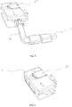
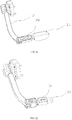
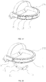
- FIG.5, FIG.6 , FIG.24, and FIG.25 it is a display device of another kind of link structure.
- a capturing device 1 is disposed at the helmet 27.
- the capturing device 1 is connected with the display device of the link structure by wiring or plugging for data communication.
- the capturing device 1 and the display device may be a whole or divided into two separate components. When they are two separate shooting components, they may be mounted on both sides of the headset device respectively, making wearing more balanced, as shown in FIG.32 .
- the display device of the link structure comprises a multi-link type base portion 14, and one end of the multi-link mechanism is disposed on the multi-link type base portion 14 by a first adjusting device 7, and the first adjusting device 7 adopts a rotating shaft structure, preferably an adjusting mechanism with damping, for example, a damped "-"shaped rotating shaft structure disposed vertically.
- the first adjusting device 7 can be used for the fast adjustment of the display module leftwards and rightwards.
- the other end of the multi-link mechanism is provided with a display device 13 as a display module by the second adjusting device 12.
- the display device 13 adopts a micro-projection display device for the convenience of carrying and light design.
- the adjusting device adopts an adjusting mechanism with a damping or rear locking adjusting mechanism, to position the display device in an adjustable position for easy observation.
- the second adjusting device 12 is used to achieve the fine adjustment of the angle of the display device 13, preferably, the second adjusting device 12 adopts a universal ball shaft device.
- the video data cables of the display device 13 are placed inside the multi-link mechanism so that they are not exposed outside, and they are aesthetic and prevent accidental damage to the data cables.
- the multi-link mechanism is a three-link structure
- the head link 8 of the three-link structure adopts a concave design
- one end of the head link 8 of the three-link structure is disposed on the multi-link type base portion 14 through a first adjusting device 7
- the other end of the head link 8 of the three-link structure is connected to the intermediate link 91 by an adjusting device, for example, a lateral damped "-"shaped rotating shaft structure.
- an adjusting device for example, a lateral damped "-"shaped rotating shaft structure.
- the intermediate link 91 has an arc design which can be designed to substantially conform to the arc shape of the surface of the helmet, or the intermediate link 91 has an L-shaped design, and the intermediate link 91 can have a hollow structure, for example, a snap-type can be adopted.
- the structure is hollow inside and is used to pass the data cables or power cables; the snap-type structure also facilitates to open the data cables of the intermediate link 91 when the function module is subsequently repaired or expanded.
- the other end of the intermediate link 91 is connected with one end of the tail link 11 through an adjusting device, for example, a damped "-"shaped rotating shaft structure.
- a damped "-"shaped rotating shaft structure is used.
- a vertically damped "-"shaped rotating shaft structure is used for adjusting the display device 13 quickly back and forth.
- the other end of the tail link 11 is disposed with a display device 13 by a second adjusting device 12.
- a friction layer is arranged on the surface of the tail link 11. Users can link the head link 8 and intermediate link 91 of the three-link structure by holding the tail link 11 or the display device 13, to achieve the quick adjustment leftwards and rightwards, up and down, and back and forth.
- the multi-link mechanism is also a three-link structure.
- the adjustment mode and linkage principle are the same as those of FIG. 5 and FIG. 6 .
- the difference is that the shape of each link is different, which is relatively simple compared to the link components shown in FIG.5 and FIG.6 , FIG.24 or FIG.25 .
- the multi-link mechanism can also adopt more link assembly modes, for example, the intermediate link can be a single-link or a multi-link mechanism, to achieve the technical problems to be solved in the present invention.
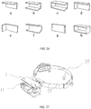
- an accommodating unit is added for accommodating the display device 13 on the basis of FIG.5 , in addition, a snapping port is provided at the accommodating unit.
- a simple accommodating unit can be designed into the above shape.
- the simple accommodating unit adopts a concave shape as shown in FIG.26b and a concave arc shape as shown in FIG.26f .
- FIG.27 to FIG.30 show that the display device is accommodated in a concave accommodating unit in FIG.26b .
- one end of the link device is disposed in the accommodating unit 3 through a link type base portion 14, the accommodating unit comprises an accommodating box 3, and a baffle assembly disposed in the accommodating box, the baffle assembly comprises a top bead spring 5 and a latching top bead 4 disposed at the top of the top bead spring, the top bead spring 5 is disposed at the spring baffle 6. Under the action of the top bead spring 5, a part of the latching top bead 4 protrudes in the hole 2 of the accommodating box 3.
- the multi-link mechanism that matches with the hole 2 is provided with a card slot 10, so that the latching top bead 4 is snapped into the card slot 10 when accommodated.
- the accommodating unit further comprises a dialing component 17 disposed on one side of the accommodating box, the dialing component comprises a dialing hand 15, a recovering spring 16 and a thimble 18, and the accommodating box is provided with a hole through which the thimble can pass, when dialing the dialing hand 15, the thimble 18 passes through the hole of the accommodating box and then withstands the multi-link mechanism, so that the multi-link mechanism overcomes the elastic force of the latching top bead 4 and then slides the latching top bead out of the card slot; after releasing the dialing hand, the recovering spring 16 returns the dialing hand 15.
- the dialing component 17 disposed on one side of the accommodating box
- the dialing component comprises a dialing hand 15, a recovering spring 16 and a thimble 18, and the accommodating box is provided with a hole through which the thimble can pass, when dialing the dialing hand 15, the thimble 18 passes through the hole of the accommodating box and then withstands the multi-link mechanism, so that the multi-link
- the link type base portion 14 is not a separate independent component.
- the contact area of the first adjusting device on the inner surface of the accommodating unit can be a link type base portion 14, at this time, the inner surface of the accommodating unit is integrally formed with the link type base portion 14 or separately formed but combined and assembled.
- an additional buffering component 29 can be disposed on the inner side of the accommodating unit.
- the multi-link mechanism plays a role of protection.
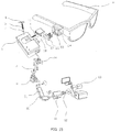
- FIG. 32 it is another embodiment when the multi-link mechanism is disposed in the inner wall of the accommodating unit.
- a thermal image capturing device is disposed on one side of the headband, and a display device with an accommodating unit is disposed on the other side.
- the thermal image capturing device and the display device can be directly connected by wires or through wires with connectors.
- the head link 8 of the three-link structure is directly mounted on the inner wall of the accommodating unit.
- the multi-link type base portion 14 and the inner wall of the accommodating unit are integrated, and the first adjusting device of the head link 8 of the three-link structure is in the contact area of the inner wall of the accommodating unit, actually it is a multi-link type base portion 14.
- the multi-link mechanism is disposed at the top of the accommodating unit, the multi-link mechanism is a three-link structure.
- the head link 8 of the three-link structure adopts a concave design.
- One end of the head link 8 of the three-link structure is disposed on the top wall of the accommodating unit by the first adjusting device 7.
- the first adjusting device of the head link 8 of the three-link structure is in the contact area of the top wall of the accommodating unit, which is actually a multi-link type base portion 14.
- the other end of the head link 8 of the three-link structure is connected to one end of the intermediate link 91 via a lateral damped "-"shaped rotating shaft structure.
- the intermediate link 91 adopts a snap-on nut fixation structure.
- the structure is hollow inside and is used to pass the data cables or power cables.
- the snap-type structure also facilitates to open the data cables of the intermediate link 91 when the function module is subsequently repaired or expanded.
- the intermediate link is stabilized by fixing with a nut after snapping.
- the other end of the intermediate link 91 is connected with one end of the tail link 11 through a joint member 30.
- a rotating shaft is provided between the joint member 30 and the intermediate link 91.
- a damped "-"shaped rotating shaft structure is used for adjusting the display device 13 quickly back and forth.
- the other end of the tail link 11 is disposed with a display device 13 by a second adjusting device 12.
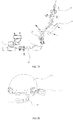
- FIG. 49 it differs from the structure in FIG. 36 in that it can be provided with various application devices, such as a measuring device, a sensing device, etc.
- a capturing device such as a thermal imager 1 can be provided.
- the mounting base of the accommodating unit or the display device has a buckle that matches the card slot of the headset device, which facilitates the flexible installation of the display device in the positions with card slots such as the front and side of the headset device, etc.
- a capturing device such as a thermal imager 1
- the display device 13 is used to display the content of the thermal imager 1.
- the accommodating unit 3 and the external device can be connected through a snapping device, as shown in FIG.15 ⁇ FIG.18 , the external device is a spectacle frame.
- a buckle is disposed on one side of the accommodating unit 3, and a matching card slot 24 is disposed at the spectacle frame.
- An electrical contact 23 is provided at the bottom of the card slot 24.
- Stepped chutes are provided on both sides of the card slot 24, and a pressing block 22 is disposed on the inner side of the card slot, and the buckle is inserted into the bottom of the card slot along the chute, and the pressing block 22 presses the buckle under the action of the spring 25.
- the buckle is snapped in the card slot 24 through the pressing block 22 and the steps of the chute.
- a control button 26 is disposed in a display device with adjustable viewing angle for controlling the display device 13, as shown in FIG. 19 , FIG. 22 or FIG. 23 , the control button 26 can be disposed at the shell of the display device 13; or can be disposed at the multi-link mechanism, as shown in FIG. 20 and FIG.21 .
- a display device with a multi-link mechanism having an accommodating groove is embedded in the headband.
- An accommodating groove 31 is embedded in the headband, and the intermediate link 91 and the tail link 11 are both provided with a certain degree of curvature.
- the curvature of the accommodating groove 31 matches the curvature of the intermediate link 91 and the tail link 11.
- a notch is provided at one side of the accommodating groove, which is used to dispose a multi-link type base portion 14.
- the multi-link mechanism is a three-link structure.
- the head link 8 of the three-link structure adopts a concave design.
- One end of the head link 8 of the three-link structure is disposed on the multi-link type base portion 14 by the first adjusting device 7.
- the other end of the head link 8 of the three-link structure is connected to one end of the intermediate link 91 via a lateral damped "-"shaped rotating shaft structure.
- the intermediate link 91 adopts an arc design, with an arc curvature matching with that of the accommodating groove 31.
- the intermediate link 91 adopts a snap-type structure.
- the structure is hollow inside and is used to pass the data cables or power cables.
- the snap-type structure also facilitates to open the data cables of the intermediate link 91 when the function module is subsequently repaired or expanded.
- the other end of the intermediate link 91 is connected with one end of the tail link 11 through a vertically damped "-"shaped rotating shaft structure.
- the damped "-"shaped rotating shaft structure is used for adjusting the display device 13 quickly back and forth.
- the other end of the tail link 11 is disposed with a display device 13 by a second adjusting device 12.
- the second adjusting device 12 is used to achieve the fine adjustment of the angle of the display device 13, preferably, the second adjusting device 12 adopts a universal ball shaft device.
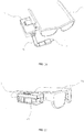
- FIG. 40 ⁇ 41 it is another structural diagram of display device with a multi-link mechanism having an accommodating groove at the headband.
- the multi-link mechanism is a two-link structure
- the second link 92 has a certain curvature
- the curvature of the accommodating groove31 is matched with the curvature of the second link 92.
- a notch is provided at one side of the accommodating groove, which is used to dispose the multi-link type base portion 14.
- the head link 8 of the two-link structure adopts a concave design.
- One end of the head link 8 is disposed on the multi-link type base portion 14 by the first adjusting device 7.
- the other end of the head link 8 is connected to one end of the second link 92 via a lateral damped "-"shaped rotating shaft structure.
- the second link 92 adopts an arc design, with an arc curvature consistent with that of the accommodating groove 31.
- the second link 92 adopts a snap-type structure.
- the structure is hollow inside and is used to pass the data cables or power cables.
- the snap-type structure also facilitates to open the data cables of the second link 92 when the function module is subsequently repaired or expanded.
- the other end of the second link 92 is disposed on the display device 13 by a second adjusting device 12.
- the second adjusting device 12 is used to achieve the fine adjustment of the angle of the display device 13, preferably, the second adjusting device 12 adopts a universal ball shaft device.
- a capturing device is provided at one side of the headband in the Example 12, for example, a thermal image capturing device, and a power module is provided on the other side.
- the display device is directly connected or plugged with the thermal image capturing device and the power module. With this setting, the weights of the two parts can be balanced.
- the multi-link mechanism is a three-link structure, which adopts a folded shape
- the accommodating unit 3 is an accommodating board.
- One end of the head link 8 of the three-link structure is disposed on the accommodating board by a first adjusting device 7, at this time, the multi-link type base portion is integrated with the accommodating board, namely, the contact place between the first adjusting device 7 and the accommodating board.
- the edge of the accommodating board is provided with a protruding protection display device.
- An accommodating groove 33 can be provided at the accommodating board for accommodating the link structure.
- the other end of the head link 8 of the three-link structure is connected to the intermediate link 94 by a lateral damped "-"shaped rotating shaft structure.
- the intermediate link 94 adopts a snap-type structure.
- the structure is hollow inside and is used to pass the data cables or power cables; the snap-type structure also facilitates to open the data cables of the intermediate link 94 when the function module is subsequently repaired or expanded.
- the other end of the intermediate link 94 is connected with one end of the tail link 93 through a vertical rotating shaft structure.
- the damped rotating shaft structure is used for adjusting the display device 13 quickly back and forth.
- the other end of the tail link 93 is disposed with a display device 13 by a second adjusting device 12.
- the second adjusting device 12 is used to achieve the fine adjustment of the angle of the display device 13, preferably, the second adjusting device 12 adopts a universal ball shaft device.
- the tail link 93 and the second adjusting device 12 are also provided with a rotating shaft.
- a single link in the multi-link mechanism may be replaced with another component such as a serpentine tube; in addition, a single link in the multi-link mechanism and the connected adjusting device may be replaced with a deformable part.
Landscapes
- Engineering & Computer Science (AREA)
- General Engineering & Computer Science (AREA)
- Mechanical Engineering (AREA)
- Physics & Mathematics (AREA)
- General Physics & Mathematics (AREA)
- Optics & Photonics (AREA)
- Multimedia (AREA)
- Signal Processing (AREA)
- Devices For Indicating Variable Information By Combining Individual Elements (AREA)
- Eyeglasses (AREA)
Applications Claiming Priority (7)
| Application Number | Priority Date | Filing Date | Title |
|---|---|---|---|
| CN201610089094 | 2016-02-17 | ||
| CN201610136537 | 2016-03-10 | ||
| CN201620296245 | 2016-04-10 | ||
| CN201620290552 | 2016-04-10 | ||
| CN201620571052 | 2016-06-14 | ||
| CN201610865122 | 2016-09-29 | ||
| PCT/CN2017/073873 WO2017140255A1 (zh) | 2016-02-17 | 2017-02-17 | 一种可调节视角的显示装置 |
Publications (2)
| Publication Number | Publication Date |
|---|---|
| EP3489736A1 true EP3489736A1 (de) | 2019-05-29 |
| EP3489736A4 EP3489736A4 (de) | 2020-05-20 |
Family
ID=58957284
Family Applications (1)
| Application Number | Title | Priority Date | Filing Date |
|---|---|---|---|
| EP17752687.8A Withdrawn EP3489736A4 (de) | 2016-02-17 | 2017-02-17 | Anzeigevorrichtung mit einstellbarem betrachtungswinkel |
Country Status (5)
| Country | Link |
|---|---|
| US (1) | US20190174041A1 (de) |
| EP (1) | EP3489736A4 (de) |
| JP (1) | JP6762681B2 (de) |
| CN (3) | CN106838567B (de) |
| WO (1) | WO2017140255A1 (de) |
Cited By (1)
| Publication number | Priority date | Publication date | Assignee | Title |
|---|---|---|---|---|
| WO2019213679A1 (en) * | 2018-05-08 | 2019-11-14 | Leader Photonics Gmbh | Support for carrying a sensor system of a fireman's helmet |
Families Citing this family (11)
| Publication number | Priority date | Publication date | Assignee | Title |
|---|---|---|---|---|
| CN108488217A (zh) * | 2018-03-26 | 2018-09-04 | 郑州润德光电科技有限公司 | 一种阻尼式万向球节 |
| CN109031662B (zh) * | 2018-07-19 | 2020-07-24 | 歌尔科技有限公司 | 增强现实设备的转轴机构和增强现实头戴设备 |
| CN109828374B (zh) * | 2019-03-27 | 2024-12-27 | 何毅 | 一种左右调节的智能眼镜 |
| CN111727340B (zh) * | 2019-05-27 | 2022-07-15 | 深圳市大疆创新科技有限公司 | 可折叠的手持云台 |
| US11054628B2 (en) * | 2019-11-13 | 2021-07-06 | Norotos, Inc. | Adjustable night vision goggle adapter |
| CN111474714A (zh) * | 2020-04-20 | 2020-07-31 | 深圳市谦视智能科技有限责任公司 | 一种近眼显示装置及可穿戴设备 |
| CN112610864B (zh) * | 2020-12-01 | 2022-11-01 | 杭州海康威视数字技术股份有限公司 | 头戴式相机及其安装架 |
| CN114046312B (zh) * | 2021-09-22 | 2022-12-30 | 天津(滨海)人工智能军民融合创新中心 | 一种双轴调节固定装置 |
| USD1110612S1 (en) * | 2022-03-09 | 2026-01-27 | Dräger Safety AG & Co. KGaA | In mask display |
| CN118475867B (zh) * | 2022-11-30 | 2026-01-13 | 京东方科技集团股份有限公司 | 头戴式显示装置 |
| CN119914813A (zh) * | 2025-04-01 | 2025-05-02 | 佳谱仪器(苏州)有限公司 | 一种便携型手持式x荧光光谱仪 |
Family Cites Families (29)
| Publication number | Priority date | Publication date | Assignee | Title |
|---|---|---|---|---|
| CN2142973Y (zh) * | 1992-12-30 | 1993-09-29 | 刘全捷 | 立体电视镜 |
| WO1996007947A1 (en) * | 1994-08-31 | 1996-03-14 | Virtual I/O, Inc. | Personal display system |
| JP2000081592A (ja) * | 1998-09-07 | 2000-03-21 | Olympus Optical Co Ltd | ヘッドマウンテッドディスプレイ装置 |
| US7370983B2 (en) * | 2000-03-02 | 2008-05-13 | Donnelly Corporation | Interior mirror assembly with display |
| NL1018198C2 (nl) * | 2001-06-01 | 2002-12-03 | Tno | Head mounted display inrichting. |
| JP3901061B2 (ja) * | 2002-08-29 | 2007-04-04 | ソニー株式会社 | ヘッドマウント装置 |
| WO2004061519A1 (ja) * | 2002-12-24 | 2004-07-22 | Nikon Corporation | ヘッドマウントディスプレイ |
| JP2004233776A (ja) * | 2003-01-31 | 2004-08-19 | Nikon Corp | ヘッドマウントディスプレイ |
| JP5055584B2 (ja) * | 2006-03-08 | 2012-10-24 | 株式会社ニコン | ヘッドマウントディスプレイ装置 |
| JP5195426B2 (ja) * | 2006-07-25 | 2013-05-08 | 株式会社ニコン | 出力装置及び映像表示装置 |
| WO2008088691A2 (en) * | 2007-01-12 | 2008-07-24 | Kopin Corporation | Head mounted monocular display device |
| US20080266768A1 (en) * | 2007-04-27 | 2008-10-30 | Drew Paul L | Adjustable display |
| JP5233941B2 (ja) * | 2009-09-30 | 2013-07-10 | ブラザー工業株式会社 | 画像表示装置 |
| CN201592673U (zh) * | 2010-02-02 | 2010-09-29 | 重庆中和天然气开发有限公司 | 货箱自动锁紧固定装置 |
| CN201732214U (zh) * | 2010-06-07 | 2011-02-02 | 贾怀昌 | 一种可自由调节位置和视角的眼镜显示器 |
| CN201836609U (zh) * | 2010-09-21 | 2011-05-18 | 安徽华东光电技术研究所 | 自由调节可折叠头盔单目显示器支承结构 |
| JP2012105117A (ja) * | 2010-11-11 | 2012-05-31 | Nikon Corp | 頭部装着型画像表示装置 |
| CN202834667U (zh) * | 2012-10-30 | 2013-03-27 | 北京航天长峰科技工业集团有限公司 | 一种头盔上单目显示器的固定与调节结构 |
| WO2014101890A1 (zh) * | 2012-12-31 | 2014-07-03 | Wang Hao | 头盔式热像装置 |
| CN104075808A (zh) * | 2012-12-31 | 2014-10-01 | 杭州美盛红外光电技术有限公司 | 头盔式热像装置 |
| AU2013101173A4 (en) * | 2013-09-02 | 2013-09-26 | Global Clean Coal Technologies Pty Ltd | Fire Fighter's Helmet |
| CN104869354A (zh) * | 2014-02-26 | 2015-08-26 | 杭州美盛红外光电技术有限公司 | 头盔式热像装置 |
| CN203722793U (zh) * | 2014-03-07 | 2014-07-16 | 北京云视智通科技有限公司 | 一种可穿戴设备 |
| CN203894475U (zh) * | 2014-05-15 | 2014-10-22 | 王傲立 | 折叠式眼镜显示器 |
| CN203882014U (zh) * | 2014-06-04 | 2014-10-15 | 上海来松电子有限公司 | 头戴眼镜式显示屏的仪表 |
| CN204570240U (zh) * | 2015-03-30 | 2015-08-19 | 贺锦辉 | 一种用于添加粉状助剂的杯盖 |
| CN204807810U (zh) * | 2015-07-29 | 2015-11-25 | 恒基伟业投资发展集团有限公司 | 一种智能眼镜 |
| CN206817079U (zh) * | 2016-04-10 | 2017-12-29 | 杭州美盛红外光电技术有限公司 | 一种可调节视角的显示装置 |
| CN206817123U (zh) * | 2016-06-14 | 2017-12-29 | 杭州美盛红外光电技术有限公司 | 一种带有收纳装置的可调节视角显示装置 |
-
2017
- 2017-02-17 EP EP17752687.8A patent/EP3489736A4/de not_active Withdrawn
- 2017-02-17 US US15/998,892 patent/US20190174041A1/en not_active Abandoned
- 2017-02-17 WO PCT/CN2017/073873 patent/WO2017140255A1/zh not_active Ceased
- 2017-02-17 CN CN201710085762.XA patent/CN106838567B/zh active Active
- 2017-02-17 CN CN201710085968.2A patent/CN106764351A/zh active Pending
- 2017-02-17 JP JP2018536183A patent/JP6762681B2/ja active Active
- 2017-02-17 CN CN201710086106.1A patent/CN106764352B/zh active Active
Cited By (1)
| Publication number | Priority date | Publication date | Assignee | Title |
|---|---|---|---|---|
| WO2019213679A1 (en) * | 2018-05-08 | 2019-11-14 | Leader Photonics Gmbh | Support for carrying a sensor system of a fireman's helmet |
Also Published As
| Publication number | Publication date |
|---|---|
| US20190174041A1 (en) | 2019-06-06 |
| EP3489736A4 (de) | 2020-05-20 |
| WO2017140255A1 (zh) | 2017-08-24 |
| CN106838567B (zh) | 2020-12-08 |
| JP2019502961A (ja) | 2019-01-31 |
| CN106764352B (zh) | 2020-12-08 |
| CN106764351A (zh) | 2017-05-31 |
| JP6762681B2 (ja) | 2020-09-30 |
| CN106838567A (zh) | 2017-06-13 |
| CN106764352A (zh) | 2017-05-31 |
Similar Documents
| Publication | Publication Date | Title |
|---|---|---|
| EP3489736A1 (de) | Anzeigevorrichtung mit einstellbarem betrachtungswinkel | |
| US9405126B1 (en) | Eye level viewfinder and three dimensional virtual reality viewing device and method | |
| CN217559406U (zh) | 用于图像捕获设备的安装系统和可展开安装系统 | |
| EP4012698B1 (de) | Anzeigevorrichtung | |
| EP4067977A1 (de) | Anzeigevorrichtung | |
| JP2016161934A (ja) | カメラを具備した端末機用据置台 | |
| US20050168824A1 (en) | Binocular virtual display imaging device | |
| US12189276B2 (en) | Multi-support accessory with integrated power supply for image capture devices | |
| US12140746B1 (en) | Night vision device | |
| WO2022062020A1 (zh) | 一种头戴设备 | |
| CN105708407A (zh) | 可穿戴语音识别内窥镜控制系统及可穿戴设备 | |
| CN206817123U (zh) | 一种带有收纳装置的可调节视角显示装置 | |
| KR20180024454A (ko) | 휴대폰 연동형 셀프촬영장치 | |
| HUP0101790A2 (hu) | Fejen viselhető tartó optoelektronikai készüléknek a felhasználó szeme előtt történő megtartásához | |
| CN206817079U (zh) | 一种可调节视角的显示装置 | |
| JP6440748B2 (ja) | カメラを具備した端末機用据置台 | |
| WO2014201987A1 (zh) | 头盔装置 | |
| CN106444039B (zh) | 头戴显示设备 | |
| CN207762532U (zh) | 一种带有收纳板的可调节视角显示装置 | |
| CN222825742U (zh) | 一种瞳距可调夜视仪 | |
| US20200012112A1 (en) | Multiple-Degree of Freedom Adjustable Discrete Type Near-Eye Display Device | |
| CN222461801U (zh) | 可穿戴设备 | |
| KR101043637B1 (ko) | 휴대용 듀얼 모니터의 카메라 모듈 결합구조 | |
| CN214381149U (zh) | 一种同屏显示热成像图像和夜视仪图像设备 | |
| CN216490720U (zh) | 一种带热靴结构的监视器保护套 |
Legal Events
| Date | Code | Title | Description |
|---|---|---|---|
| PUAI | Public reference made under article 153(3) epc to a published international application that has entered the european phase |
Free format text: ORIGINAL CODE: 0009012 |
|
| 17P | Request for examination filed |
Effective date: 20181219 |
|
| AK | Designated contracting states |
Kind code of ref document: A1 Designated state(s): AL AT BE BG CH CY CZ DE DK EE ES FI FR GB GR HR HU IE IS IT LI LT LU LV MC MK MT NL NO PL PT RO RS SE SI SK SM TR |
|
| A4 | Supplementary search report drawn up and despatched |
Effective date: 20200420 |
|
| RIC1 | Information provided on ipc code assigned before grant |
Ipc: G02B 27/01 20060101AFI20200414BHEP Ipc: A42B 3/04 20060101ALI20200414BHEP |
|
| STAA | Information on the status of an ep patent application or granted ep patent |
Free format text: STATUS: THE APPLICATION HAS BEEN WITHDRAWN |
|
| 18W | Application withdrawn |
Effective date: 20200514 |