EP3489802B1 - Informationsverarbeitungsvorrichtung, informationsverarbeitungsverfahren und programm - Google Patents
Informationsverarbeitungsvorrichtung, informationsverarbeitungsverfahren und programm Download PDFInfo
- Publication number
- EP3489802B1 EP3489802B1 EP17833803.4A EP17833803A EP3489802B1 EP 3489802 B1 EP3489802 B1 EP 3489802B1 EP 17833803 A EP17833803 A EP 17833803A EP 3489802 B1 EP3489802 B1 EP 3489802B1
- Authority
- EP
- European Patent Office
- Prior art keywords
- determination
- unit
- gesture
- information processing
- determination unit
- Prior art date
- Legal status (The legal status is an assumption and is not a legal conclusion. Google has not performed a legal analysis and makes no representation as to the accuracy of the status listed.)
- Active
Links
Images


Classifications
-
- G—PHYSICS
- G06—COMPUTING OR CALCULATING; COUNTING
- G06F—ELECTRIC DIGITAL DATA PROCESSING
- G06F1/00—Details not covered by groups G06F3/00 - G06F13/00 and G06F21/00
- G06F1/26—Power supply means, e.g. regulation thereof
- G06F1/32—Means for saving power
- G06F1/3203—Power management, i.e. event-based initiation of a power-saving mode
- G06F1/3234—Power saving characterised by the action undertaken
- G06F1/325—Power saving in peripheral device
- G06F1/3265—Power saving in display device
-
- G—PHYSICS
- G06—COMPUTING OR CALCULATING; COUNTING
- G06F—ELECTRIC DIGITAL DATA PROCESSING
- G06F1/00—Details not covered by groups G06F3/00 - G06F13/00 and G06F21/00
- G06F1/16—Constructional details or arrangements
- G06F1/1613—Constructional details or arrangements for portable computers
- G06F1/163—Wearable computers, e.g. on a belt
-
- G—PHYSICS
- G06—COMPUTING OR CALCULATING; COUNTING
- G06F—ELECTRIC DIGITAL DATA PROCESSING
- G06F1/00—Details not covered by groups G06F3/00 - G06F13/00 and G06F21/00
- G06F1/16—Constructional details or arrangements
- G06F1/1613—Constructional details or arrangements for portable computers
- G06F1/1633—Constructional details or arrangements of portable computers not specific to the type of enclosures covered by groups G06F1/1615 - G06F1/1626
- G06F1/1684—Constructional details or arrangements related to integrated I/O peripherals not covered by groups G06F1/1635 - G06F1/1675
- G06F1/1694—Constructional details or arrangements related to integrated I/O peripherals not covered by groups G06F1/1635 - G06F1/1675 the I/O peripheral being a single or a set of motion sensors for pointer control or gesture input obtained by sensing movements of the portable computer
-
- G—PHYSICS
- G06—COMPUTING OR CALCULATING; COUNTING
- G06F—ELECTRIC DIGITAL DATA PROCESSING
- G06F1/00—Details not covered by groups G06F3/00 - G06F13/00 and G06F21/00
- G06F1/26—Power supply means, e.g. regulation thereof
- G06F1/32—Means for saving power
- G06F1/3203—Power management, i.e. event-based initiation of a power-saving mode
- G06F1/3206—Monitoring of events, devices or parameters that trigger a change in power modality
- G06F1/3215—Monitoring of peripheral devices
-
- G—PHYSICS
- G06—COMPUTING OR CALCULATING; COUNTING
- G06F—ELECTRIC DIGITAL DATA PROCESSING
- G06F1/00—Details not covered by groups G06F3/00 - G06F13/00 and G06F21/00
- G06F1/26—Power supply means, e.g. regulation thereof
- G06F1/32—Means for saving power
- G06F1/3203—Power management, i.e. event-based initiation of a power-saving mode
- G06F1/3206—Monitoring of events, devices or parameters that trigger a change in power modality
- G06F1/3231—Monitoring the presence, absence or movement of users
-
- G—PHYSICS
- G06—COMPUTING OR CALCULATING; COUNTING
- G06F—ELECTRIC DIGITAL DATA PROCESSING
- G06F1/00—Details not covered by groups G06F3/00 - G06F13/00 and G06F21/00
- G06F1/26—Power supply means, e.g. regulation thereof
- G06F1/32—Means for saving power
- G06F1/3203—Power management, i.e. event-based initiation of a power-saving mode
- G06F1/3234—Power saving characterised by the action undertaken
- G06F1/3293—Power saving characterised by the action undertaken by switching to a less power-consuming processor, e.g. sub-CPU
-
- G—PHYSICS
- G06—COMPUTING OR CALCULATING; COUNTING
- G06F—ELECTRIC DIGITAL DATA PROCESSING
- G06F3/00—Input arrangements for transferring data to be processed into a form capable of being handled by the computer; Output arrangements for transferring data from processing unit to output unit, e.g. interface arrangements
- G06F3/01—Input arrangements or combined input and output arrangements for interaction between user and computer
- G06F3/017—Gesture based interaction, e.g. based on a set of recognized hand gestures
-
- H—ELECTRICITY
- H04—ELECTRIC COMMUNICATION TECHNIQUE
- H04W—WIRELESS COMMUNICATION NETWORKS
- H04W52/00—Power management, e.g. Transmission Power Control [TPC] or power classes
- H04W52/02—Power saving arrangements
- H04W52/0209—Power saving arrangements in terminal devices
- H04W52/0251—Power saving arrangements in terminal devices using monitoring of local events, e.g. events related to user activity
- H04W52/0254—Power saving arrangements in terminal devices using monitoring of local events, e.g. events related to user activity detecting a user operation or a tactile contact or a motion of the device
-
- H—ELECTRICITY
- H04—ELECTRIC COMMUNICATION TECHNIQUE
- H04W—WIRELESS COMMUNICATION NETWORKS
- H04W52/00—Power management, e.g. Transmission Power Control [TPC] or power classes
- H04W52/02—Power saving arrangements
- H04W52/0209—Power saving arrangements in terminal devices
- H04W52/0261—Power saving arrangements in terminal devices managing power supply demand, e.g. depending on battery level
- H04W52/0267—Power saving arrangements in terminal devices managing power supply demand, e.g. depending on battery level by controlling user interface components
- H04W52/027—Power saving arrangements in terminal devices managing power supply demand, e.g. depending on battery level by controlling user interface components by controlling a display operation or backlight unit
-
- H—ELECTRICITY
- H04—ELECTRIC COMMUNICATION TECHNIQUE
- H04W—WIRELESS COMMUNICATION NETWORKS
- H04W52/00—Power management, e.g. Transmission Power Control [TPC] or power classes
- H04W52/02—Power saving arrangements
- H04W52/0209—Power saving arrangements in terminal devices
- H04W52/0261—Power saving arrangements in terminal devices managing power supply demand, e.g. depending on battery level
- H04W52/0274—Power saving arrangements in terminal devices managing power supply demand, e.g. depending on battery level by switching on or off the equipment or parts thereof
-
- H—ELECTRICITY
- H04—ELECTRIC COMMUNICATION TECHNIQUE
- H04M—TELEPHONIC COMMUNICATION
- H04M2250/00—Details of telephonic subscriber devices
- H04M2250/12—Details of telephonic subscriber devices including a sensor for measuring a physical value, e.g. temperature or motion
-
- Y—GENERAL TAGGING OF NEW TECHNOLOGICAL DEVELOPMENTS; GENERAL TAGGING OF CROSS-SECTIONAL TECHNOLOGIES SPANNING OVER SEVERAL SECTIONS OF THE IPC; TECHNICAL SUBJECTS COVERED BY FORMER USPC CROSS-REFERENCE ART COLLECTIONS [XRACs] AND DIGESTS
- Y02—TECHNOLOGIES OR APPLICATIONS FOR MITIGATION OR ADAPTATION AGAINST CLIMATE CHANGE
- Y02D—CLIMATE CHANGE MITIGATION TECHNOLOGIES IN INFORMATION AND COMMUNICATION TECHNOLOGIES [ICT], I.E. INFORMATION AND COMMUNICATION TECHNOLOGIES AIMING AT THE REDUCTION OF THEIR OWN ENERGY USE
- Y02D10/00—Energy efficient computing, e.g. low power processors, power management or thermal management
-
- Y—GENERAL TAGGING OF NEW TECHNOLOGICAL DEVELOPMENTS; GENERAL TAGGING OF CROSS-SECTIONAL TECHNOLOGIES SPANNING OVER SEVERAL SECTIONS OF THE IPC; TECHNICAL SUBJECTS COVERED BY FORMER USPC CROSS-REFERENCE ART COLLECTIONS [XRACs] AND DIGESTS
- Y02—TECHNOLOGIES OR APPLICATIONS FOR MITIGATION OR ADAPTATION AGAINST CLIMATE CHANGE
- Y02D—CLIMATE CHANGE MITIGATION TECHNOLOGIES IN INFORMATION AND COMMUNICATION TECHNOLOGIES [ICT], I.E. INFORMATION AND COMMUNICATION TECHNOLOGIES AIMING AT THE REDUCTION OF THEIR OWN ENERGY USE
- Y02D30/00—Reducing energy consumption in communication networks
- Y02D30/70—Reducing energy consumption in communication networks in wireless communication networks
Definitions
- the present technology relates to an information processing apparatus, an information processing method, and a program which can be applied to a wearable device.
- Patent Literature 1 discloses a wristband type display control apparatus provided with a control unit, an input unit, a sensor unit, a storage unit, a communication unit, a display unit, and the like.
- Patent Literature 2 discloses an electronic apparatus capable of attaining a long lifetime of a battery while suppressing power consumption of the apparatus.
- US 2016/018872 A1 discloses a wearable computing device that can detect device-raising gestures. For example, onboard motion sensors of the device can detect movement of the device in real time and infer information about the spatial orientation of the device.
- the device can detect a raise gesture, which can be a motion pattern consistent with the user moving the device's display into his line of sight.
- a raise gesture can be a motion pattern consistent with the user moving the device's display into his line of sight.
- the device can activate its display and/or other components. Detection of a raise gesture can occur in stages, and activation of different components can occur at different stages.
- an object of the present technology is to provide an information processing apparatus, an information processing method, and a program which can perform a detection of a change in state of a user with basic electric power.
- the present invention provides an information processing apparatus in accordance with independent claim 1.
- the present invention provides an information processing method in accordance with independent claim 10.
- the present invention provides a computer program product in accordance with independent claim 11.
- An information processing apparatus includes: a signal generation unit, a first determination unit, and a second determination unit.
- the signal generation unit processes an output of a sensor unit attached to a detection target, and generates a trigger signal at a time when a state change of the detection target is detected.
- the first determination unit is brought out of hibernation and activated when receiving the trigger signal, determines the state change of the detection target from the output of the sensor unit by a first determination criterion, and outputs a determination impossibility signal in a case where the determination is impossible.
- the second determination unit is brought out of hibernation and activated when receiving the determination impossibility signal, and determines the state change of the detection target from the output of the sensor unit by a second determination criterion different from the first determination criterion.
- the first determination unit is configured to be started at a time when the state change of the detection target is detected, and the second determination unit is configured to be started in a case where determination by the first determination unit is impossible. As a result, it is possible to determine the state of the detection target while suppressing power consumption.
- the signal generation unit may be configured to detect a motion of a user who wears the detection target from the state change of the detection target, and the first determination unit and the second determination unit is configured to determine, on the basis of a mode of the motion of the user, whether a corresponding gesture candidate exists or not from among a plurality of gesture candidates set in advance.
- the first determination unit may be configured to execute a first determination process of specifying a gesture candidate corresponding to the mode of the motion of the user from among the plurality of gesture candidates, and output the determination impossibility signal in a case where specifying the gesture candidate is impossible.
- the second determination unit may execute a second determination process of specifying a gesture candidate having a highest correlation with the mode of the motion of the user from among the plurality of gesture candidates.
- the information processing apparatus may further include a setting unit that sets the plurality of gesture candidates.
- the signal generation unit may change a standard by which the trigger signal is generated in accordance with a kind of the plurality of gesture candidates set.
- the signal generation unit may detect a motion of an arm of the user who wears the detection target, and the first determination unit and the second determination unit each may specify any one of a raising operation, a lowering operation, a twisting operation, and a shaking operation of the arm of the user.
- the first determination unit and the second determination unit may be brought into hibernation again after the state change of the detection target is determined.
- the information processing apparatus may further include a buffer memory capable of chronologically storing the output of the sensor unit.
- An information processing method includes bringing out of hibernation and activating a first determination unit which determines a state change of a detection target by a first determination criterion, when the state change of the detection target is detected on the basis of an output of a sensor unit attached to the detection target.
- a second determination unit which determines the state change of the detection target by a second determination criterion different from the first determination criterion is brought out of hibernation and activated, when the first determination unit is incapable of performing determination.
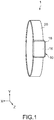
- Fig. 1 is a schematic perspective view showing an information processing apparatus according to an embodiment of the present technology.
- An information processing apparatus 1 according to this embodiment is configured by a watch type or wristband type wearable device.
- the information processing apparatus 1 in this embodiment has a basic function of displaying a time or the like and a gesture recognition function of detecting a motion of an arm of a user and switching a display or control. It should be noted that the information processing apparatus 1 may be used as a terminal apparatus capable of performing transmission and reception of e-mail or the like, browse of web information, and measurement, management, and the like of biological information of the user in accordance with a specification thereof.
- the information processing apparatus 1 includes a main body 10 and a band unit 20 which supports the main body 10 and is put on the arm of the user.
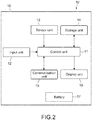
- Fig. 2 is a block diagram for explaining the configuration of the main body 10.
- the main body 10 includes a control unit 11, an input unit 12, a sensor unit 13, a storage unit 14, a communication unit 15, a display unit 16, a battery 17, and a casing 18 which contains those.
- the control unit 11 is configured by a computer, and performs control of an entire operation of the information processing apparatus 1 by executing a program stored in the storage unit 14 or another storage medium.
- the control unit 11 includes one or a plurality of processors such as a CPU (Central Processing Unit), a GPU (Graphics Processing Unit), a DSP (Digital Signal Processor), and an SoC (System on Chip).
- processors such as a CPU (Central Processing Unit), a GPU (Graphics Processing Unit), a DSP (Digital Signal Processor), and an SoC (System on Chip).
- the control unit 11 determines whether a significant gesture input of the user exists or not and a kind thereof, and controls the communication unit 15, the display unit 16, and the like in accordance with a determination result thereof.
- control unit 11 is configured to reduce the power consumption of the battery 17 in such a manner that the display unit 16 is turned off, or the gesture determination is not performed until a significant operation of the user is detected.
- the input unit 12 receives an input operation by the user and outputs the received operation to the control unit 11.
- the input unit 12 may be constituted of various devices such as keys and switches, or may be constituted of a touch sensor. In a case where the input unit 12 is constituted of the touch sensor, the input unit 12 may be configured integrally with the display unit 16.
- the sensor unit 13 detects an acceleration that acts on the casing 18, and outputs the acceleration to the control unit 11.
- the sensor unit 13 mainly has a function of detecting the motion of the arm and the posture of the user who wears the information processing apparatus 1.
- the sensor unit 13 is constituted of a sensor unit including an acceleration sensor capable of detecting accelerations in triaxial directions orthogonal to one another (X, Y and Z axis directions in Fig. 1 . The same holds true for the following.).
- a sampling frequency of the sensor unit 13 can be set as appropriate, for example, set to 8 Hz.
- the acceleration sensor may be constituted of a plurality of sensors that detect accelerations of the respective axes or a single sensor. Further, the sensor unit 13 may include not only the acceleration sensor but also another motion sensor such as an angular velocity sensor, a biological sensor capable of detecting a body temperature, a pulse rate, or perspiration, or the like of a user.
- another motion sensor such as an angular velocity sensor, a biological sensor capable of detecting a body temperature, a pulse rate, or perspiration, or the like of a user.
- the storage unit 14 is typically constituted of a semiconductor memory, and stores a program for causing the control unit 11 to operate, a parameter, a function, and the like necessary to detect the motion of the user and determine a gesture. Further, the storage unit 14 is configured to be capable of storing various data to be used by the program. Further, the storage unit 14 stores various application software to be executed by the control unit 11.
- the communication unit 15 is configured to be capable of being communicated with a handheld terminal, a server, another information processing apparatus 1, or the like in a wireless or wired manner.
- the communication unit 15 is configured to be capable of being communicated with a handheld terminal (smart phone, mobile phone, laptop personal computer, or the like) of a user who wears the information processing apparatus 1.
- the communication unit 15 includes a communication circuit, an antenna, or the like, transmits an output of the control unit 11 to the handheld terminal, or receives input information from the handheld terminal and outputs to the control unit 11.
- the display unit 16 receives a display control signal from the control unit 11 and displays various information, and constitutes a screen of the information processing apparatus 1.
- the display unit 16 typically includes a display element such as an LCD (Liquid Crystal Display) an organic EL (Electro-Luminescence) display.
- the display unit 16 displays various images such as a time, input keys, reception information, and measurement information.
- the battery 17 supplies electric power necessary for an operation of the main body 10, and is typically constituted of an electricity storage element such as a primary battery and a secondary battery. Further, the battery 17 may be constituted of a power generation element capable of generating electric power by solar light, vibrations, or the like.
- the casing 18 is a casing made of metal or a synthetic resin and has a thin, rectangular parallelepiped shape in this embodiment.
- the shape is not limited to this.
- the casing 18 may be formed in a disc shape or another geometric shape.
- the casing 18 can be put on the user through the band unit 20.
- the sensor unit 13 sets the casing 18 as a detection target.
- the control unit 11 determines a motion of an arm (gesture) of the user through a change in posture of the casing 18.
- the sensor unit 13 may be directly put on the arm of the user.
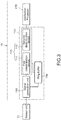
- Fig. 3 is a block diagram showing a configuration of the control unit 11.
- the control unit 11 detects the motion of the arm of the user, and performs a predetermined process in accordance with the motion.
- the control unit 11 includes a determination circuit unit 11A and an execution circuit unit 11B.
- the determination circuit unit 11A is a circuit which determines whether the motion of the user detected by the sensor unit 13 is significant information for gesture determination or not.
- the execution circuit unit 11B is a main processor which executes various applications in accordance with the determined gesture operation.
- the determination circuit unit 11A includes a signal generation unit 110, a determination unit 113, and a ring buffer 114.
- the determination unit 113 includes a first determination device 111 and a second determination device 112.
- the signal generation unit 110 processes an output of the sensor unit 13 and generates a trigger signal at a time of detecting a state change relating to a posture of the user.
- the signal generation unit 110 processes an output of the sensor unit 13, and detects whether there is a state change relating to the posture of the user or not.
- the state change relating to the posture of the user means the motion of the arm of the user specifically.
- the signal generation unit 110 At a time when the signal generation unit 110 detects the motion of the user, the signal generation unit 110 generates a trigger signal to the determination unit 113.
- the signal generation unit 110 is operated at all times from a startup of the information processing apparatus 1 to monitor the output of the sensor unit 13.
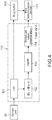
- Fig. 4 is a block diagram showing a configuration example of the signal generation unit 110.
- the signal generation unit 110 includes a low-pass filter (LPF) 101, a difference circuit 102, a norm calculation circuit 103, and a threshold value determination circuit 104.
- LPF low-pass filter
- the LPF 101 is a filter function for removing an unnecessary noise from the output of the sensor unit 13 (acceleration signal in each triaxial direction) and detecting a gesture which should be truly evaluated.
- a cutoff frequency of the LPF 101 is set to an appropriate value (for example, 4 Hz) which enables removing of a high frequency component of the acceleration signal which can be generated during walking, running, or boarding on a vehicle by the user.
- An output of the LPF 101 is output to the difference circuit 102 and the ring buffer 114.
- the signal generation unit 110 has a determination function that a temporal differentiation is performed for the acceleration signals in the triaxial directions output from the LPF 101 by the difference circuit 102 respectively, and a norm is calculated by the norm calculation circuit 103.
- the threshold value determination circuit 104 determines whether a value of the determination function exceeds a preset threshold value or not.
- the threshold value determination circuit 104 has a unique threshold value for each of the triaxial directions, and generates, in a case where at least one of norm values of the axes exceeds the threshold value, a trigger signal to output the signal to the first determination device 111.
- the first determination device 111 is brought out of hibernation (sleep state) and activated upon reception of the trigger signal, determines the motion of the arm of the user from the output of the sensor unit 13 by a first determination criterion, and outputs a determination impossibility signal in a case where the determination cannot be performed.
- the first determination device 111 For the first determination device 111, a simple CPU having a relatively low processing speed can be used. The first determination device 111 maintains hibernation until the signal generation unit 110 generates the trigger signal, and reduces power consumption of the battery 17.
- the first determination device 111 determines whether there is a corresponding gesture candidate from a plurality of preset gesture candidates or not by the first determination criterion.
- output data of the LPF 101 which is stored in the ring buffer 114 is referenced.
- the plurality of gesture candidates stored in the storage unit 14 is referenced.
- the plurality of gesture candidates are not particularly limited.
- the plurality of gesture candidates include a raising operation of the arm of the user, a lowering operation thereof, a shaking operation thereof, a twisting operation thereof, and the like, for example (see Fig. 6 ).
- the first determination device 111 performs a first determination process for specifying a gesture candidate corresponding to the mode of the motion of the user from among the plurality of gesture candidates.
- the first determination process for example, a relatively simple algorism is executed.
- the algorism from among the plurality of gesture candidates stored in the storage unit 14, a gesture candidate having data corresponding to acceleration data for underpinning the mode of the motion of the user is specified.
- the first determination device 111 outputs information related to the specified gesture candidate to the execution circuit unit 11B.
- the first determination device 111 when it is impossible to specify the gesture candidate, the first determination device 111 outputs the determination impossibility signal.
- the time when it is impossible to specify the gesture candidate include a time when it is impossible to recognize which gesture candidate the mode corresponds to.
- the second determination device 112 is brought out of the hibernation and activated upon reception of the determination impossibility signal, and determines a posture of the casing 18 from the output of the sensor unit 13 by a second determination criterion different from the first determination criterion.
- the second determination device 112 is constituted of a CPU having a higher performance than the first determination device 111, for example, involving a larger power consumption, a higher calculation capability, or a higher processing speed than the first determination device 111, or a combination of those.
- the second determination device 112 maintains the hibernation until the first determination device 111 generates the determination impossibility signal, with the result that power consumption of the battery 17 is reduced.
- the second determination device 112 determines whether there is a corresponding gesture candidate from the preset plurality of gesture candidates. For the mode of the motion of the user, output data of the LPF 101 stored in the ring buffer 114 is referenced, and for the determination of the gesture candidate, the plurality of gesture candidates stored in the storage unit 14 are referenced.
- the second determination device 112 performs a second determination process of specifying a gesture candidate having a highest correlation with the mode of the motion of the user from among the plurality of gesture candidates.
- an advanced algorism as compared to the first determination process is executed. For example, it is possible to use an algorism with a relatively larger computation amount like computation using a determination device of machine learning.
- an advanced determination criterion as described above it is possible to specify, with high accuracy, a gesture candidate with a greater probability, which is a gesture candidate that coincides with an intention of the user.
- Information related to the gesture candidate specified in the second determination process is output to the execution circuit unit 11B.
- the information related to the gesture candidate may be output from the first determination device 111 or may be output from the second determination device 112.
- the first determination device 111 and second determination device 112 are shifted to the hibernation again at a time when the information related to the specified gesture candidate is output to the execution circuit unit 11B, or at a time when it is determined that there is no gesture candidate corresponding to the motion of the user, with the result that the power consumption of the battery 17 is suppressed.
- the second determination device 112 requires a larger power consumption than the first determination unit 111, so the hibernation of the second determination device 112 brings about a large advantage in a reduction of the power consumption.
- the ring buffer 114 is constituted of a buffer memory capable of storing the output of the sensor unit 13 (acceleration signal in each triaxial direction) in a chronological order.
- the ring buffer 114 only has to have such a capacity that there is an information amount used to specify the gesture candidate corresponding to the motion of the user in the first and second determination devices 111, 112, for example, only has to have such a capacity that sensor information of past one second can be accumulated.
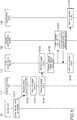
- FIG. 5 is a sequence diagram showing a typical operation example of the information processing apparatus 1. In this case, a flow of the gesture recognition will be described.
- the sensor unit 13 reads the value of the acceleration sensor of each axis at a predetermined time interval. After that, the sensor unit 13 applies the filter function (LPF 101), and calculates a trigger determination function (difference circuit 102, norm calculation circuit 103). When a condition that the value exceeds a fixed value is satisfied, for example, the sensor unit 13 performs a trigger generation event (generate a trigger signal) (Steps 101 to 104) .
- the determination unit 113 When the trigger is generated, the determination unit 113 is started up, and a gesture detection process is performed. At a time of detecting a gesture, the output of the sensor unit 13 before the trigger is generated is held in the ring buffer 114, so the output is also used to perform the calculation.
- An algorism of the gesture detection is divided into a plurality of algorisms.
- an algorism which is light but is less accurate is calculated by the first determination device 111 (Steps 105, 106).
- a gesture event is generated (Step 108).
- the second determination device 112 is started up to perform a more accurate process, thereby performing the determination (Step 107).
- a determination device by machine learning may be used.
- the gesture event when the gesture is recognized in the second determination device 112, the gesture event is generated in the first determination device 111. Alternatively, in the second determination device 112, the gesture event may be generated.
- the execution circuit unit 11B executes application software on the basis of information related to the recognized or specified gesture candidate (Step 109).
- a fixed-time interrupt refers to resetting by calculating appropriateness of the trigger on the basis of a movement intensity or the like regularly, because there is a case where when the condition of the trigger is strictly set at a time when a motion is strenuous or the like, the motion is reduced thereafter, and the trigger is not appropriate.
- Figs. 6A to 6D are schematic diagrams each showing an example of a kind of the gesture.
- A shows an arm raising operation
- B shows an arm lowering operation
- C shows an arm shaking operation
- D shows an arm twisting operation.
- the raising operation shown in Fig. 6A is recognized by an output of the acceleration sensor in the Z axis direction principally.
- this is estimated as an operation of confirming a display with a display surface of the display unit 16 of the information processing apparatus 1 lifted upwards by the user.
- the display unit 16 maintained to be a light-out state is lighted, and displays predetermined information such as a current time.
- the lowering operation shown in Fig. 6B is recognized by the output of the acceleration sensor in the Z axis direction principally.
- this is estimated as termination of confirming the display unit 16 by the user.
- the display unit 16 shifted from the lighted state to the light-out state.
- the shaking operation shown in Fig. 6C is recognized by the output of the acceleration sensor in the Z axis direction principally.
- the twisting operation shown in Fig. 6D is recognized by outputs of the acceleration sensors in an X axis direction and a Y axis direction principally.
- application software corresponding to those is executed.
- selecting music to be reproduced by the handheld terminal or the like, adjusting a volume, or the like may be performed.
- the information processing apparatus 1 in this embodiment has the gesture recognition function for recognizing the motion of the user. Therefore, it is possible to perform an input operation without operating a button or a touch panel, which improves convenience of the user.
- the determination unit 113 for the gesture recognition is divided into the simple CPU (first determination device 111) which involves a relatively low processing speed and the high-performance CPU (second determination device 112) which involves a relatively high processing speed, and stands by in a hibernation mode until the trigger is generated. Further, when the trigger is generated, first, the first determination device 111 is started up. The second determination device 112 is started up in a case where determination by the first determination device 111 is impossible. As a result, an average power consumption of the control unit 11 can be significantly reduced, so it is possible to recognize the gesture corresponding to the motion of the user while minimizing the power consumption.
- the output of the sensor unit 13 is accumulated in the ring buffer 114 in a chronological order.
- a motion which is obviously not a gesture can be determined by a relatively simple calculation in some cases. For example, in a case where a sensor value (output of the sensor unit 13) is a certain value and is not completely changed, a possibility that this is a gesture is 0. If a bit more complicated motion is caused, for example, in a case where the display unit 16 is directed downwards in a raising gesture, a possibility that this is a raising gesture to look at a watch is slim.
- a terminal determines both of the arm lowering operation and the finger tapping operation by using the acceleration sensor.
- the arm lowering operation is a large motion and thus easily determined, so the operation can be processed in the first determination device 111.
- determination of the finger tapping requires a highspeed computation using the determination device of machine learning, so the operation is necessary to be processed in the second determination device 112.
- an assumption is made that recognizing a gesture is carried out by only one kind at one time.
- the first determination device 111 recognizes an arm lowering motion. If the motion is recognized, it is unnecessary to determine the finger tapping, so the second determination device 112 is not used.
- the second determination device 112 performs a determination process for the finger tapping.
- Fig. 7 is a block diagram showing a configuration of a control unit 211 in an information processing apparatus according to a second embodiment of the present technology.
- a configuration different from the first embodiment will be mainly described. Similar configurations to those of the first embodiment will be denoted by similar reference numerals or symbols, and a description of those will be omitted or simplified.
- control unit 211 includes a setting unit 115.
- the setting unit 115 sets a plurality of gesture candidates to be recognized.
- the determination circuit unit 11A that executes the gesture recognition performs the gesture recognition upon reception of a request from the execution circuit unit 11B that uses the gesture specified by the determination circuit unit 11A, and after the recognition of the gesture, issues a gesture event to the execution circuit unit 11B.
- the determination circuit unit 11A when receiving a request of a gesture of a kind necessary to execute an application from the execution circuit unit 11B at a time of starting the application, the determination circuit unit 11A sets the kind of the gesture which should be determined by the determination unit 113. The determination circuit unit 11A recognizes only the gesture of the kind requested first, and transmits the gesture to the execution circuit unit 11B as the event.
- the setting unit 115 calculates kinds of such gestures as to cover just a right number of gestures required by the applications, and performs a recognition process in accordance with this. For example, as shown in Fig. 8 , in a case where the execution circuit unit 11B requires, as a first application B1, raising (a) and lowering (b), and as a second application B2, raising (a) and shaking gesture (c), the determination circuit unit 11A recognizes three kinds of gestures, that is, raising (a), lowering (b), and shaking (c), and notifies the requesting applications of the event.
- the determination circuit unit 11A receives the gesture recognition requests from the plurality of applications, and recognizes the required gestures.
- a trigger function, a determination device used for the gesture determination, and a necessary acceleration sensor mode may be different. This is varied depending on a request from the application or a state of the arm or the terminal at that time. That is, the gestures recognized by the determination circuit unit 11A are varied depending on not only the request from the application but also the state of the arm of the user.
- the determination circuit unit 11A is capable of changing a generation standard of the trigger signal in the signal generation unit 110 depending on the kind of the gesture to be recognized.
- the generation standard of the trigger signal include a sampling frequency of the acceleration sensor (sensor unit 13), a cutoff frequency of the low-pass filter, a trigger determination function of the threshold value or the like of the threshold value determination circuit 104, and the like. Changing the generation standard of the trigger signal is performed in the setting unit 115, for example.
- a sampling frequency of the acceleration sensor is set to be lower.
- the sampling frequency of the acceleration sensor is set to be higher.
- the arm gesture recognition at a time of recognizing four kinds of the arm raising and lowering gestures (arm_up, arm_down), an arm twisting gesture (twist), and an arm shaking gesture (shake), a position of the arm is changed between arm up and arm down at a time of starting the gesture and at a time of ending the gesture. Therefore, lowering a frequency of the acceleration sensor and observing a direction change of a gravitational acceleration as the trigger function are sufficient.
- the twist and the shake the position of the arm is not changed at the start time and at the end time.
- the frequency of the acceleration sensor has to be set to be higher, and as the trigger function, the arm motion itself has to be observed.
- the former mode and the latter mode do not exist at the same time.
- one of the modes is selected. In this case, switching between the former mode and the latter mode is decided on the basis of whether a recognition of the twist/shake is necessary or not in response to a request of the application.
- the change in position of the arm is generated in the case of the raising and the lowering, so such a trigger as to be generated with a difference can be used.
- the position of the arm is returned to an original position, so a trigger is set in such a manner that not a difference but a norm of the acceleration exceeds a fixed value, for example. That is, in Fig. 4 , a function of the difference circuit 102 is invalidated.
- Fig. 9 is a block diagram showing a configuration of a sensor apparatus 310 as an information processing apparatus in this embodiment.
- configurations different from the first embodiment will be mainly described. Configurations similar to those of the first embodiment will be denoted by similar reference numerals or symbols, and a description of those will be omitted or simplified.
- the sensor apparatus 310 includes a sensor unit 31 equipped with the trigger function, a CPU 32, and a ring buffer 33.
- the sensor unit 31 corresponds to a mixed circuit of the sensor unit 13 and the signal generation unit 110 in the first embodiment.
- the determination device 32 corresponds to the determination unit 113 in the first embodiment, and is started up upon reception of a trigger signal from the sensor unit 31.
- the ring buffer 33 corresponds to the ring buffer 114 in the first embodiment.
- the determination device 32 may be provided with the first and second determination devices 111, 112 as in the first embodiment, or may be provided with one of those. In the following, an example is used in which the determination device 32 is constituted of a single CPU.
- the sensor unit 31 itself has a trigger function, and causes the determination device 32 which is normally in hibernation to be activated by a trigger.
- a function which can be used as the trigger may be limited. For example, it is possible to provide only such a simple function that a specific axis exceeds a threshold value, or absolute values of all the axes exceed threshold values.
- the trigger (a) when used, an erroneous generation of the trigger during walking or running is less caused.
- the trigger in a condition in which the screen is already faced upwards, for example, during working while sitting down at a desk, the trigger cannot be generated.
- the trigger (b) when used, the trigger can be generated in various conditions including sitting down at a desk.
- the erroneous generation is often caused during walking or running.
- the trigger of (a) and the trigger of (b) are separately used. Just before the determination device 32 is shifted to the hibernation from an activation state, in accordance with the position of the arm at that time, a determination function of a trigger detection circuit is set.
- the output of the sensor unit 31 includes a signal related to a motion along multiaxial directions including a gravity direction (Z axis direction).
- the sensor apparatus 310 has a plurality of detection standards related to a state change which are different from each other depending on a posture just before detecting the state change of the posture of the arm. Specifically, the sensor apparatus 310 switches between a first detection mode in which the state change is detected in accordance with the state of the arm in a case of a preceding gesture recognition on the basis of a form of the motion of the arm along the gravity direction and a second detection mode in which the state change is detected on the basis of a form of the motion of the detection target in the multiaxial directions and achieves execution.
- a trigger (hereinafter, also referred to as Z axis trigger) based on the fact that an output of the acceleration sensor in the Z axis direction exceeds the threshold value is set.
- a trigger (hereinafter, also referred to as motion trigger) based on the fact that a norm of an output of the acceleration sensor in the triaxial direction exceeds the threshold value is set.
- the Z axis trigger By setting the Z axis trigger at a time when the arm is lowered, it is possible to reduce an erroneous generation rate without an additional circuit such as a low-pass filter even in an environment in which the erroneous generation is likely to be caused, for example, during an active movement like walking or running. Further, by switching to the motion trigger using all the axes at a time when the arm is raised, it is possible to turn on the screen by slightly twisting a wrist during working at a desk. By switching the trigger without turning on the screen, it is possible to light the screen by a natural motion at all times without being aware of a current mode by the user.
- Examples of a specific algorism of the motion trigger include generation when an absolute value of each axis of the acceleration sensor of a wristband becomes a value significantly larger than 1 G (for example, 1.2 G). In addition, in any one of the axes, when a difference of the acceleration with a preceding frame is significantly larger than 0 (for example, 0.2 G), the generation may be caused.
- the specific algorism of the Z axis trigger exceeding a threshold value (for example, 0.6 G) by the acceleration in the Z axis direction may be preferably used.
- the motion trigger is appropriate to a case where the arm is raised, for example, during working at a desk.
- the Z axis trigger is appropriate to a case where the arm is lowered, for example, during walking or lowering the arm while sitting on a sofa.
- Fig. 10 is a diagram for explaining a transition relationship between the Z axis trigger and the motion trigger.
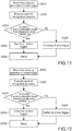
- Fig. 11 and Fig. 12 each are a flowchart for explaining an operation example of the sensor apparatus 310.
- the Z axis trigger detects a motion of the arm.
- the motion trigger detects a change of a posture of an upper surface of the arm, namely, a posture in a direction of a dial face of a watch.
- the Z axis trigger is generated when the Z axis acceleration acc z exceeds a first threshold value THRES 0, and the determination device 32 is returned from hibernation (sleep state) (Step 201).
- a degree of the Z axis acceleration acc_z is determined (Steps 202 and 203).
- the detection mode is switched to the motion trigger (Step 204).
- the Z axis trigger is maintained (Step 205).
- the generation is caused by referring to an absolute value of each axis.
- the determination device 32 is brought into the hibernation (Step 206).
- the motion trigger is generated when the Z axis acceleration acc z exceeds a second threshold value THRES 1, and the determination device 32 is returned from the hibernation (sleep state) (Step 301).
- the Z axis acceleration acc z and the second threshold value THRES 1 are compared (Step 303).
- the trigger is switched to the Z axis trigger (Step 304).
- the motion trigger is maintained (Step 305). It is desirable that THRES 1 be set to be smaller than THRES 0. As a result, in a case where the Z axis acceleration acc z is vibrated within a range close to THRES 0, it is possible to prevent the trigger from being frequently generated.
- the wearable device of the wristband type is used as an example, but is not limited to this.
- the present technology can be applied to a glasses-type wearable device. In this case, it is possible to recognize a predetermined gesture (nodding, shaking a head, or the like) from a motion of a head of a user.
- the information processing apparatus 1 provided with the sensor unit 13 is used as an example.
- the sensor unit 13 and the control unit 11 may be separately configured.
- the control unit 11 may be configured as a handheld terminal or a server device which can communicate with the sensor unit 13 via a wireless network or the like.
- generation algorism of the sensor trigger described in the third embodiment may be applied to the signal generation unit 110 in the first and second embodiments.
- the information processing apparatus used to perform the gesture recognition of the user is used as an example.
- the present technology can be applied to posture determination or posture control for a vehicle or an unmanned autonomous flying body.
- the information processing apparatus may be configured in such a manner that a state change such as a voice and a heart rate of the user may be detected and recognized.
Landscapes
- Engineering & Computer Science (AREA)
- Theoretical Computer Science (AREA)
- General Engineering & Computer Science (AREA)
- Physics & Mathematics (AREA)
- General Physics & Mathematics (AREA)
- Computer Hardware Design (AREA)
- Human Computer Interaction (AREA)
- Computer Networks & Wireless Communication (AREA)
- Signal Processing (AREA)
- User Interface Of Digital Computer (AREA)
Claims (11)
- Informationsverarbeitungsvorrichtung (1), umfassend:eine Signalerzeugungseinheit (110), die dazu ausgelegt ist, eine Ausgabe einer Sensoreinheit (13) zu verarbeiten, die an einem durch einen Benutzer zu tragenden Gehäuse (18) angebracht ist, wobei das Gehäuse (18) von der Sensoreinheit (13) als Erkennungsziel gesetzt ist, und ein Auslösesignal zu einem Zeitpunkt zu erzeugen, zu dem eine Zustandsänderung des Erkennungsziels erkannt wird;eine erste Bestimmungseinheit (111), die dazu ausgelegt ist, beim Empfangen des Auslösesignals aus dem Ruhezustand gebracht und aktiviert zu werden, die Zustandsänderung des Erkennungsziels anhand der Ausgabe der Sensoreinheit (13) durch ein erstes Bestimmungskriterium zu bestimmen und ein Bestimmungsunmöglichkeitssignal in einem Fall auszugeben, in dem die Bestimmung unmöglich ist; undeine zweite Bestimmungseinheit (112), die dazu ausgelegt ist, beim Empfangen des Bestimmungsunmöglichkeitssignals aus dem Ruhezustand gebracht und aktiviert zu werden und die Zustandsänderung des Erkennungsziels anhand der Ausgabe der Sensoreinheit (13) durch ein zweites Bestimmungskriterium, das von dem ersten Bestimmungskriterium verschieden ist, zu bestimmen; wobeidie Signalerzeugungseinheit (110) dazu ausgelegt ist, eine Bewegung des Benutzers anhand der Zustandsänderung des Erkennungsziels zu erkennen, unddie erste Bestimmungseinheit (111) und die zweite Bestimmungseinheit (112) dazu ausgelegt sind, auf Grundlage eines Modus der Bewegung des Benutzers zu bestimmen, ob ein entsprechender Gestenkandidat aus einer Vielzahl von im Voraus festgelegten Gestenkandidaten vorhanden ist oder nicht, und wobeidie zweite Bestimmungseinheit (112) dazu ausgelegt ist, eine höhere Leistungsaufnahme als die der ersten Bestimmungseinheit (111) aufzuweisen.
- Informationsverarbeitungsvorrichtung (1) gemäß Anspruch 1, wobei
die erste Bestimmungseinheit (111) dazu ausgelegt ist, einen ersten Bestimmungsvorgang zum Spezifizieren eines Gestenkandidaten entsprechend dem Modus der Bewegung des Benutzers aus der Vielzahl von Gestenkandidaten auszuführen und das Bestimmungsunmöglichkeitssignal in einem Fall auszugeben, in dem das Spezifizieren des Gestenkandidaten unmöglich ist. - Informationsverarbeitungsvorrichtung (1) gemäß Anspruch 1, wobei
die zweite Bestimmungseinheit (112) dazu ausgelegt ist, einen zweiten Bestimmungsvorgang zum Spezifizieren eines Gestenkandidaten mit einer höchsten Korrelation mit dem Modus der Bewegung des Benutzers aus der Vielzahl von Gestenkandidaten auszuführen. - Informationsverarbeitungsvorrichtung (1) gemäß Anspruch 1, ferner umfassend:eine Festlegungseinheit, die dazu ausgelegt ist, die Vielzahl von Gestenkandidaten festzulegen, wobeidie Signalerzeugungseinheit (110) dazu ausgelegt ist, einen Standard zu ändern, durch den das Auslösesignal gemäß einer Art der Vielzahl von festgelegten Gestenkandidaten erzeugt wird.
- Informationsverarbeitungsvorrichtung (1) gemäß Anspruch 1, wobei
die Signalerzeugungseinheit (110) dazu ausgelegt ist, eine Bewegung eines Arms des Benutzers, der das Erkennungsziel trägt, zu erkennen, und
die erste Bestimmungseinheit (111) und die zweite Bestimmungseinheit (112) jeweils dazu ausgelegt sind, einen Hebevorgang, einen Absenkvorgang, einen Verdrehvorgang und einen Schüttelvorgang des Arms des Benutzers zu spezifizieren. - Informationsverarbeitungsvorrichtung (1) gemäß Anspruch 1, wobei
die erste Bestimmungseinheit (111) und die zweite Bestimmungseinheit (112) dazu ausgelegt sind, nach dem Bestimmen der Zustandsänderung des Erkennungsziels wieder in den Ruhezustand gebracht zu werden. - Informationsverarbeitungsvorrichtung (1) gemäß Anspruch 1, ferner umfassend:
einen Pufferspeicher (114), der in der Lage ist, die Ausgabe der Sensoreinheit (13) chronologisch zu speichern. - Informationsverarbeitungsvorrichtung (1) gemäß Anspruch 1, wobei
die Signalerzeugungseinheit (110) dazu ausgelegt ist, das Auslösesignal zu einem Zeitpunkt einer Zustandsänderung in Bezug auf eine Haltung des Erkennungsziels zu erzeugen. - Informationsverarbeitungsvorrichtung (1) gemäß Anspruch 1, wobei das Gehäuse (18) zum Aufnehmen der Signalerzeugungseinheit (110), der ersten Bestimmungseinheit (111) und der zweiten Bestimmungseinheit (112) ausgelegt ist.
- Informationsverarbeitungsverfahren, umfassend:Herausholen aus dem Ruhezustand und Aktivieren einer ersten Bestimmungseinheit (111), die eine Zustandsänderung eines Erkennungsziels durch ein erstes Bestimmungskriterium bestimmt, wenn die Zustandsänderung des Erkennungsziels auf Grundlage einer Ausgabe einer Sensoreinheit (13) erkannt wird, die an einem durch einen Benutzer zu tragenden Gehäuse (18) angebracht ist, wobei das Gehäuse (18) von der Sensoreinheit (13) als Erkennungsziel gesetzt ist;Herausholen aus dem Ruhezustand und Aktivieren einer zweiten Bestimmungseinheit (112), die die Zustandsänderung des Erkennungsziels durch ein zweites Bestimmungskriterium bestimmt, das von dem ersten Bestimmungskriterium verschieden ist, wenn die erste Bestimmungseinheit (111) nicht in der Lage ist, das Bestimmen durchzuführen; undErkennen einer Bewegung des Benutzers anhand der Zustandsänderung des Erkennungsziels; wobeidie erste Bestimmungseinheit (111) und die zweite Bestimmungseinheit (112) auf Grundlage eines Modus der Bewegung des Benutzers bestimmen, ob ein entsprechender Gestenkandidat aus einer Vielzahl von im Voraus festgelegten Gestenkandidaten vorhanden ist oder nicht, und wobeidie zweite Bestimmungseinheit (112) eine höhere Leistungsaufnahme als die der ersten Bestimmungseinheit (111) aufweist.
- Computerprogrammprodukt, das Computeranweisungen umfasst, um die Informationsverarbeitungsvorrichtung (1) gemäß einem der Ansprüche 1 bis 9 zu veranlassen, das Verfahren gemäß Anspruch 10 auszuführen.
Applications Claiming Priority (2)
| Application Number | Priority Date | Filing Date | Title |
|---|---|---|---|
| JP2016145621 | 2016-07-25 | ||
| PCT/JP2017/018811 WO2018020792A1 (ja) | 2016-07-25 | 2017-05-19 | 情報処理装置、情報処理方法及びプログラム |
Publications (3)
| Publication Number | Publication Date |
|---|---|
| EP3489802A1 EP3489802A1 (de) | 2019-05-29 |
| EP3489802A4 EP3489802A4 (de) | 2019-07-31 |
| EP3489802B1 true EP3489802B1 (de) | 2021-04-28 |
Family
ID=61017053
Family Applications (1)
| Application Number | Title | Priority Date | Filing Date |
|---|---|---|---|
| EP17833803.4A Active EP3489802B1 (de) | 2016-07-25 | 2017-05-19 | Informationsverarbeitungsvorrichtung, informationsverarbeitungsverfahren und programm |
Country Status (4)
| Country | Link |
|---|---|
| US (1) | US11216072B2 (de) |
| EP (1) | EP3489802B1 (de) |
| JP (1) | JP6891891B2 (de) |
| WO (1) | WO2018020792A1 (de) |
Families Citing this family (3)
| Publication number | Priority date | Publication date | Assignee | Title |
|---|---|---|---|---|
| IT201900019037A1 (it) | 2019-10-16 | 2021-04-16 | St Microelectronics Srl | Metodo perfezionato per rilevare un gesto di inclinazione del polso e unita' elettronica e dispositivo elettronico indossabile che implementano il medesimo |
| DE102020209939A1 (de) * | 2020-08-06 | 2022-02-10 | Robert Bosch Gesellschaft mit beschränkter Haftung | Vorrichtung und Verfahren zum Erkennen von Kopfgesten |
| US12299214B2 (en) * | 2023-08-09 | 2025-05-13 | Stmicroelectronics International N.V. | Low power lift-up gesture detection with shake rejection |
Family Cites Families (16)
| Publication number | Priority date | Publication date | Assignee | Title |
|---|---|---|---|---|
| CA2062106C (en) * | 1991-12-23 | 2002-08-20 | Gregg Marwin | Object sensing system for bar code laser scanners |
| JP4127691B2 (ja) * | 2004-10-04 | 2008-07-30 | 株式会社東芝 | 文字認識装置及びその方法 |
| CN104503608B (zh) | 2007-07-09 | 2017-08-11 | 索尼株式会社 | 电子设备及其控制方法 |
| US8131465B2 (en) * | 2007-12-14 | 2012-03-06 | Qualcomm Incorporated | Motion detection for tracking |
| JP5747695B2 (ja) * | 2011-07-07 | 2015-07-15 | 富士通株式会社 | 画像処理装置、画像処理方法及び画像処理プログラム |
| US9063731B2 (en) * | 2012-08-27 | 2015-06-23 | Samsung Electronics Co., Ltd. | Ultra low power apparatus and method to wake up a main processor |
| US9081571B2 (en) * | 2012-11-29 | 2015-07-14 | Amazon Technologies, Inc. | Gesture detection management for an electronic device |
| JP2015064680A (ja) * | 2013-09-24 | 2015-04-09 | 京セラ株式会社 | 電子機器、電子機器の制御方法、および電子機器の制御プログラム |
| JP2015125616A (ja) | 2013-12-26 | 2015-07-06 | ソニー株式会社 | 表示制御装置、表示制御方法およびプログラム |
| JP6144192B2 (ja) * | 2013-12-27 | 2017-06-07 | 株式会社Nttドコモ | 画像認識装置、及び画像認識方法 |
| US9513703B2 (en) * | 2013-12-27 | 2016-12-06 | Intel Corporation | Gesture-based waking and control system for wearable devices |
| JP2015179493A (ja) * | 2014-02-27 | 2015-10-08 | 株式会社ログバー | ジェスチャ入力システム |
| JP2015186183A (ja) * | 2014-03-26 | 2015-10-22 | 株式会社Nttドコモ | 通信端末及び通信方法 |
| US10101793B2 (en) * | 2014-07-18 | 2018-10-16 | Apple Inc. | Raise gesture detection in a device |
| US9788277B2 (en) * | 2015-01-15 | 2017-10-10 | Mediatek Inc. | Power saving mechanism for in-pocket detection |
| US9804679B2 (en) * | 2015-07-03 | 2017-10-31 | Google Inc. | Touchless user interface navigation using gestures |
-
2017
- 2017-05-19 EP EP17833803.4A patent/EP3489802B1/de active Active
- 2017-05-19 US US16/305,701 patent/US11216072B2/en not_active Expired - Fee Related
- 2017-05-19 WO PCT/JP2017/018811 patent/WO2018020792A1/ja not_active Ceased
- 2017-05-19 JP JP2018529376A patent/JP6891891B2/ja not_active Expired - Fee Related
Non-Patent Citations (1)
| Title |
|---|
| None * |
Also Published As
| Publication number | Publication date |
|---|---|
| EP3489802A4 (de) | 2019-07-31 |
| US20200379573A1 (en) | 2020-12-03 |
| WO2018020792A1 (ja) | 2018-02-01 |
| US11216072B2 (en) | 2022-01-04 |
| JPWO2018020792A1 (ja) | 2019-05-09 |
| JP6891891B2 (ja) | 2021-06-18 |
| EP3489802A1 (de) | 2019-05-29 |
Similar Documents
| Publication | Publication Date | Title |
|---|---|---|
| US20220244826A1 (en) | Transition and Interaction Model for Wearable Electronic Device | |
| JP6804586B2 (ja) | 着用式電子デバイスでのgui転移 | |
| KR102087989B1 (ko) | 착용식 전자 디바이스에 의한 원격 전자 디바이스의 제어 | |
| KR102125560B1 (ko) | 착용식 전자 디바이스 상에 광학 센서의 배치 | |
| KR102139665B1 (ko) | 착용식 전자 디바이스 | |
| US9804679B2 (en) | Touchless user interface navigation using gestures | |
| EP2733578B1 (de) | Benutzergesteneingabe in eine tragbare elektronische Vorrichtung mit Bewegung der Vorrichtung | |
| EP2733581B1 (de) | Benutzergesteneingabe in einer tragbaren elektronischen Vorrichtung mit nach außen schauendem Vorrichtungssensor | |
| EP3281089B1 (de) | Intelligente vorrichtung und verfahren zum betrieb davon | |
| EP3164785B1 (de) | Benutzerschnittstellensteuerung einer wearable-vorrichtung | |
| KR20140064692A (ko) | 착용식 전자 디바이스로부터 프로세싱의 위임 | |
| US11216072B2 (en) | Information processing apparatus, information processing method, and program | |
| CN118525261A (zh) | 用于处理触摸输入的方法和电子设备 |
Legal Events
| Date | Code | Title | Description |
|---|---|---|---|
| STAA | Information on the status of an ep patent application or granted ep patent |
Free format text: STATUS: THE INTERNATIONAL PUBLICATION HAS BEEN MADE |
|
| PUAI | Public reference made under article 153(3) epc to a published international application that has entered the european phase |
Free format text: ORIGINAL CODE: 0009012 |
|
| STAA | Information on the status of an ep patent application or granted ep patent |
Free format text: STATUS: REQUEST FOR EXAMINATION WAS MADE |
|
| 17P | Request for examination filed |
Effective date: 20190218 |
|
| AK | Designated contracting states |
Kind code of ref document: A1 Designated state(s): AL AT BE BG CH CY CZ DE DK EE ES FI FR GB GR HR HU IE IS IT LI LT LU LV MC MK MT NL NO PL PT RO RS SE SI SK SM TR |
|
| AX | Request for extension of the european patent |
Extension state: BA ME |
|
| A4 | Supplementary search report drawn up and despatched |
Effective date: 20190628 |
|
| RIC1 | Information provided on ipc code assigned before grant |
Ipc: G06F 1/3293 20190101ALI20190624BHEP Ipc: G06F 3/01 20060101AFI20190624BHEP Ipc: H04M 1/00 20060101ALI20190624BHEP Ipc: H04M 1/73 20060101ALI20190624BHEP Ipc: H04W 52/02 20090101ALI20190624BHEP |
|
| DAV | Request for validation of the european patent (deleted) | ||
| DAX | Request for extension of the european patent (deleted) | ||
| RIC1 | Information provided on ipc code assigned before grant |
Ipc: H04M 1/00 20060101ALI20200122BHEP Ipc: G06F 1/3234 20190101ALI20200122BHEP Ipc: G06F 1/16 20060101ALI20200122BHEP Ipc: G06F 1/3215 20190101ALI20200122BHEP Ipc: H04W 52/02 20090101ALI20200122BHEP Ipc: G06F 3/01 20060101AFI20200122BHEP Ipc: G06F 1/3293 20190101ALI20200122BHEP Ipc: G06F 1/3231 20190101ALI20200122BHEP |
|
| GRAP | Despatch of communication of intention to grant a patent |
Free format text: ORIGINAL CODE: EPIDOSNIGR1 |
|
| STAA | Information on the status of an ep patent application or granted ep patent |
Free format text: STATUS: GRANT OF PATENT IS INTENDED |
|
| INTG | Intention to grant announced |
Effective date: 20200504 |
|
| GRAJ | Information related to disapproval of communication of intention to grant by the applicant or resumption of examination proceedings by the epo deleted |
Free format text: ORIGINAL CODE: EPIDOSDIGR1 |
|
| STAA | Information on the status of an ep patent application or granted ep patent |
Free format text: STATUS: REQUEST FOR EXAMINATION WAS MADE |
|
| INTC | Intention to grant announced (deleted) | ||
| GRAS | Grant fee paid |
Free format text: ORIGINAL CODE: EPIDOSNIGR3 |
|
| STAA | Information on the status of an ep patent application or granted ep patent |
Free format text: STATUS: GRANT OF PATENT IS INTENDED |
|
| GRAP | Despatch of communication of intention to grant a patent |
Free format text: ORIGINAL CODE: EPIDOSNIGR1 |
|
| INTG | Intention to grant announced |
Effective date: 20201123 |
|
| GRAA | (expected) grant |
Free format text: ORIGINAL CODE: 0009210 |
|
| STAA | Information on the status of an ep patent application or granted ep patent |
Free format text: STATUS: THE PATENT HAS BEEN GRANTED |
|
| AK | Designated contracting states |
Kind code of ref document: B1 Designated state(s): AL AT BE BG CH CY CZ DE DK EE ES FI FR GB GR HR HU IE IS IT LI LT LU LV MC MK MT NL NO PL PT RO RS SE SI SK SM TR |
|
| REG | Reference to a national code |
Ref country code: GB Ref legal event code: FG4D |
|
| REG | Reference to a national code |
Ref country code: CH Ref legal event code: EP |
|
| REG | Reference to a national code |
Ref country code: AT Ref legal event code: REF Ref document number: 1387826 Country of ref document: AT Kind code of ref document: T Effective date: 20210515 |
|
| REG | Reference to a national code |
Ref country code: DE Ref legal event code: R096 Ref document number: 602017037782 Country of ref document: DE |
|
| REG | Reference to a national code |
Ref country code: IE Ref legal event code: FG4D |
|
| RAP4 | Party data changed (patent owner data changed or rights of a patent transferred) |
Owner name: SONY GROUP CORPORATION |
|
| REG | Reference to a national code |
Ref country code: LT Ref legal event code: MG9D |
|
| REG | Reference to a national code |
Ref country code: AT Ref legal event code: MK05 Ref document number: 1387826 Country of ref document: AT Kind code of ref document: T Effective date: 20210428 |
|
| PG25 | Lapsed in a contracting state [announced via postgrant information from national office to epo] |
Ref country code: LT Free format text: LAPSE BECAUSE OF FAILURE TO SUBMIT A TRANSLATION OF THE DESCRIPTION OR TO PAY THE FEE WITHIN THE PRESCRIBED TIME-LIMIT Effective date: 20210428 Ref country code: FI Free format text: LAPSE BECAUSE OF FAILURE TO SUBMIT A TRANSLATION OF THE DESCRIPTION OR TO PAY THE FEE WITHIN THE PRESCRIBED TIME-LIMIT Effective date: 20210428 Ref country code: HR Free format text: LAPSE BECAUSE OF FAILURE TO SUBMIT A TRANSLATION OF THE DESCRIPTION OR TO PAY THE FEE WITHIN THE PRESCRIBED TIME-LIMIT Effective date: 20210428 Ref country code: BG Free format text: LAPSE BECAUSE OF FAILURE TO SUBMIT A TRANSLATION OF THE DESCRIPTION OR TO PAY THE FEE WITHIN THE PRESCRIBED TIME-LIMIT Effective date: 20210728 Ref country code: AT Free format text: LAPSE BECAUSE OF FAILURE TO SUBMIT A TRANSLATION OF THE DESCRIPTION OR TO PAY THE FEE WITHIN THE PRESCRIBED TIME-LIMIT Effective date: 20210428 Ref country code: NL Free format text: LAPSE BECAUSE OF FAILURE TO SUBMIT A TRANSLATION OF THE DESCRIPTION OR TO PAY THE FEE WITHIN THE PRESCRIBED TIME-LIMIT Effective date: 20210428 |
|
| PG25 | Lapsed in a contracting state [announced via postgrant information from national office to epo] |
Ref country code: IS Free format text: LAPSE BECAUSE OF FAILURE TO SUBMIT A TRANSLATION OF THE DESCRIPTION OR TO PAY THE FEE WITHIN THE PRESCRIBED TIME-LIMIT Effective date: 20210828 Ref country code: GR Free format text: LAPSE BECAUSE OF FAILURE TO SUBMIT A TRANSLATION OF THE DESCRIPTION OR TO PAY THE FEE WITHIN THE PRESCRIBED TIME-LIMIT Effective date: 20210729 Ref country code: PT Free format text: LAPSE BECAUSE OF FAILURE TO SUBMIT A TRANSLATION OF THE DESCRIPTION OR TO PAY THE FEE WITHIN THE PRESCRIBED TIME-LIMIT Effective date: 20210830 Ref country code: LV Free format text: LAPSE BECAUSE OF FAILURE TO SUBMIT A TRANSLATION OF THE DESCRIPTION OR TO PAY THE FEE WITHIN THE PRESCRIBED TIME-LIMIT Effective date: 20210428 Ref country code: PL Free format text: LAPSE BECAUSE OF FAILURE TO SUBMIT A TRANSLATION OF THE DESCRIPTION OR TO PAY THE FEE WITHIN THE PRESCRIBED TIME-LIMIT Effective date: 20210428 Ref country code: NO Free format text: LAPSE BECAUSE OF FAILURE TO SUBMIT A TRANSLATION OF THE DESCRIPTION OR TO PAY THE FEE WITHIN THE PRESCRIBED TIME-LIMIT Effective date: 20210728 Ref country code: RS Free format text: LAPSE BECAUSE OF FAILURE TO SUBMIT A TRANSLATION OF THE DESCRIPTION OR TO PAY THE FEE WITHIN THE PRESCRIBED TIME-LIMIT Effective date: 20210428 Ref country code: SE Free format text: LAPSE BECAUSE OF FAILURE TO SUBMIT A TRANSLATION OF THE DESCRIPTION OR TO PAY THE FEE WITHIN THE PRESCRIBED TIME-LIMIT Effective date: 20210428 |
|
| REG | Reference to a national code |
Ref country code: NL Ref legal event code: MP Effective date: 20210428 |
|
| REG | Reference to a national code |
Ref country code: CH Ref legal event code: PL |
|
| PG25 | Lapsed in a contracting state [announced via postgrant information from national office to epo] |
Ref country code: RO Free format text: LAPSE BECAUSE OF FAILURE TO SUBMIT A TRANSLATION OF THE DESCRIPTION OR TO PAY THE FEE WITHIN THE PRESCRIBED TIME-LIMIT Effective date: 20210428 Ref country code: CZ Free format text: LAPSE BECAUSE OF FAILURE TO SUBMIT A TRANSLATION OF THE DESCRIPTION OR TO PAY THE FEE WITHIN THE PRESCRIBED TIME-LIMIT Effective date: 20210428 Ref country code: EE Free format text: LAPSE BECAUSE OF FAILURE TO SUBMIT A TRANSLATION OF THE DESCRIPTION OR TO PAY THE FEE WITHIN THE PRESCRIBED TIME-LIMIT Effective date: 20210428 Ref country code: DK Free format text: LAPSE BECAUSE OF FAILURE TO SUBMIT A TRANSLATION OF THE DESCRIPTION OR TO PAY THE FEE WITHIN THE PRESCRIBED TIME-LIMIT Effective date: 20210428 Ref country code: CH Free format text: LAPSE BECAUSE OF NON-PAYMENT OF DUE FEES Effective date: 20210531 Ref country code: LU Free format text: LAPSE BECAUSE OF NON-PAYMENT OF DUE FEES Effective date: 20210519 Ref country code: LI Free format text: LAPSE BECAUSE OF NON-PAYMENT OF DUE FEES Effective date: 20210531 Ref country code: MC Free format text: LAPSE BECAUSE OF FAILURE TO SUBMIT A TRANSLATION OF THE DESCRIPTION OR TO PAY THE FEE WITHIN THE PRESCRIBED TIME-LIMIT Effective date: 20210428 Ref country code: SK Free format text: LAPSE BECAUSE OF FAILURE TO SUBMIT A TRANSLATION OF THE DESCRIPTION OR TO PAY THE FEE WITHIN THE PRESCRIBED TIME-LIMIT Effective date: 20210428 Ref country code: SM Free format text: LAPSE BECAUSE OF FAILURE TO SUBMIT A TRANSLATION OF THE DESCRIPTION OR TO PAY THE FEE WITHIN THE PRESCRIBED TIME-LIMIT Effective date: 20210428 Ref country code: ES Free format text: LAPSE BECAUSE OF FAILURE TO SUBMIT A TRANSLATION OF THE DESCRIPTION OR TO PAY THE FEE WITHIN THE PRESCRIBED TIME-LIMIT Effective date: 20210428 |
|
| REG | Reference to a national code |
Ref country code: DE Ref legal event code: R097 Ref document number: 602017037782 Country of ref document: DE |
|
| REG | Reference to a national code |
Ref country code: BE Ref legal event code: MM Effective date: 20210531 |
|
| PLBE | No opposition filed within time limit |
Free format text: ORIGINAL CODE: 0009261 |
|
| STAA | Information on the status of an ep patent application or granted ep patent |
Free format text: STATUS: NO OPPOSITION FILED WITHIN TIME LIMIT |
|
| GBPC | Gb: european patent ceased through non-payment of renewal fee |
Effective date: 20210728 |
|
| 26N | No opposition filed |
Effective date: 20220131 |
|
| PG25 | Lapsed in a contracting state [announced via postgrant information from national office to epo] |
Ref country code: IE Free format text: LAPSE BECAUSE OF NON-PAYMENT OF DUE FEES Effective date: 20210519 Ref country code: GB Free format text: LAPSE BECAUSE OF NON-PAYMENT OF DUE FEES Effective date: 20210728 |
|
| PG25 | Lapsed in a contracting state [announced via postgrant information from national office to epo] |
Ref country code: IS Free format text: LAPSE BECAUSE OF FAILURE TO SUBMIT A TRANSLATION OF THE DESCRIPTION OR TO PAY THE FEE WITHIN THE PRESCRIBED TIME-LIMIT Effective date: 20210828 Ref country code: FR Free format text: LAPSE BECAUSE OF NON-PAYMENT OF DUE FEES Effective date: 20210628 Ref country code: AL Free format text: LAPSE BECAUSE OF FAILURE TO SUBMIT A TRANSLATION OF THE DESCRIPTION OR TO PAY THE FEE WITHIN THE PRESCRIBED TIME-LIMIT Effective date: 20210428 |
|
| PG25 | Lapsed in a contracting state [announced via postgrant information from national office to epo] |
Ref country code: IT Free format text: LAPSE BECAUSE OF FAILURE TO SUBMIT A TRANSLATION OF THE DESCRIPTION OR TO PAY THE FEE WITHIN THE PRESCRIBED TIME-LIMIT Effective date: 20210428 Ref country code: BE Free format text: LAPSE BECAUSE OF NON-PAYMENT OF DUE FEES Effective date: 20210531 |
|
| PG25 | Lapsed in a contracting state [announced via postgrant information from national office to epo] |
Ref country code: CY Free format text: LAPSE BECAUSE OF FAILURE TO SUBMIT A TRANSLATION OF THE DESCRIPTION OR TO PAY THE FEE WITHIN THE PRESCRIBED TIME-LIMIT Effective date: 20210428 |
|
| P01 | Opt-out of the competence of the unified patent court (upc) registered |
Effective date: 20230528 |
|
| PG25 | Lapsed in a contracting state [announced via postgrant information from national office to epo] |
Ref country code: HU Free format text: LAPSE BECAUSE OF FAILURE TO SUBMIT A TRANSLATION OF THE DESCRIPTION OR TO PAY THE FEE WITHIN THE PRESCRIBED TIME-LIMIT; INVALID AB INITIO Effective date: 20170519 |
|
| PG25 | Lapsed in a contracting state [announced via postgrant information from national office to epo] |
Ref country code: MK Free format text: LAPSE BECAUSE OF FAILURE TO SUBMIT A TRANSLATION OF THE DESCRIPTION OR TO PAY THE FEE WITHIN THE PRESCRIBED TIME-LIMIT Effective date: 20210428 |
|
| PG25 | Lapsed in a contracting state [announced via postgrant information from national office to epo] |
Ref country code: TR Free format text: LAPSE BECAUSE OF FAILURE TO SUBMIT A TRANSLATION OF THE DESCRIPTION OR TO PAY THE FEE WITHIN THE PRESCRIBED TIME-LIMIT Effective date: 20210428 |
|
| PGFP | Annual fee paid to national office [announced via postgrant information from national office to epo] |
Ref country code: DE Payment date: 20240418 Year of fee payment: 8 |
|
| PG25 | Lapsed in a contracting state [announced via postgrant information from national office to epo] |
Ref country code: MT Free format text: LAPSE BECAUSE OF FAILURE TO SUBMIT A TRANSLATION OF THE DESCRIPTION OR TO PAY THE FEE WITHIN THE PRESCRIBED TIME-LIMIT Effective date: 20210428 |
|
| REG | Reference to a national code |
Ref country code: DE Ref legal event code: R119 Ref document number: 602017037782 Country of ref document: DE |
|
| PG25 | Lapsed in a contracting state [announced via postgrant information from national office to epo] |
Ref country code: DE Free format text: LAPSE BECAUSE OF NON-PAYMENT OF DUE FEES Effective date: 20251202 |