EP3490184A1 - Verfahren zum senden oder empfangen von abwärtsstreckensteuerinformationen in einem drahtloskommunikationssystem und vorrichtung dafür - Google Patents
Verfahren zum senden oder empfangen von abwärtsstreckensteuerinformationen in einem drahtloskommunikationssystem und vorrichtung dafür Download PDFInfo
- Publication number
- EP3490184A1 EP3490184A1 EP17831379.7A EP17831379A EP3490184A1 EP 3490184 A1 EP3490184 A1 EP 3490184A1 EP 17831379 A EP17831379 A EP 17831379A EP 3490184 A1 EP3490184 A1 EP 3490184A1
- Authority
- EP
- European Patent Office
- Prior art keywords
- beams
- information
- downlink control
- coreset
- subframe
- Prior art date
- Legal status (The legal status is an assumption and is not a legal conclusion. Google has not performed a legal analysis and makes no representation as to the accuracy of the status listed.)
- Granted
Links
Images


Classifications
-
- H—ELECTRICITY
- H04—ELECTRIC COMMUNICATION TECHNIQUE
- H04L—TRANSMISSION OF DIGITAL INFORMATION, e.g. TELEGRAPHIC COMMUNICATION
- H04L5/00—Arrangements affording multiple use of the transmission path
- H04L5/003—Arrangements for allocating sub-channels of the transmission path
- H04L5/0053—Allocation of signalling, i.e. of overhead other than pilot signals
-
- H—ELECTRICITY
- H04—ELECTRIC COMMUNICATION TECHNIQUE
- H04W—WIRELESS COMMUNICATION NETWORKS
- H04W72/00—Local resource management
- H04W72/04—Wireless resource allocation
- H04W72/044—Wireless resource allocation based on the type of the allocated resource
- H04W72/046—Wireless resource allocation based on the type of the allocated resource the resource being in the space domain, e.g. beams
-
- H—ELECTRICITY
- H04—ELECTRIC COMMUNICATION TECHNIQUE
- H04L—TRANSMISSION OF DIGITAL INFORMATION, e.g. TELEGRAPHIC COMMUNICATION
- H04L5/00—Arrangements affording multiple use of the transmission path
-
- H—ELECTRICITY
- H04—ELECTRIC COMMUNICATION TECHNIQUE
- H04B—TRANSMISSION
- H04B7/00—Radio transmission systems, i.e. using radiation field
- H04B7/02—Diversity systems; Multi-antenna system, i.e. transmission or reception using multiple antennas
- H04B7/04—Diversity systems; Multi-antenna system, i.e. transmission or reception using multiple antennas using two or more spaced independent antennas
- H04B7/0413—MIMO systems
- H04B7/0417—Feedback systems
-
- H—ELECTRICITY
- H04—ELECTRIC COMMUNICATION TECHNIQUE
- H04L—TRANSMISSION OF DIGITAL INFORMATION, e.g. TELEGRAPHIC COMMUNICATION
- H04L25/00—Baseband systems
- H04L25/02—Details ; arrangements for supplying electrical power along data transmission lines
- H04L25/0202—Channel estimation
- H04L25/022—Channel estimation of frequency response
-
- H—ELECTRICITY
- H04—ELECTRIC COMMUNICATION TECHNIQUE
- H04L—TRANSMISSION OF DIGITAL INFORMATION, e.g. TELEGRAPHIC COMMUNICATION
- H04L25/00—Baseband systems
- H04L25/02—Details ; arrangements for supplying electrical power along data transmission lines
- H04L25/0202—Channel estimation
- H04L25/0224—Channel estimation using sounding signals
-
- H—ELECTRICITY
- H04—ELECTRIC COMMUNICATION TECHNIQUE
- H04L—TRANSMISSION OF DIGITAL INFORMATION, e.g. TELEGRAPHIC COMMUNICATION
- H04L27/00—Modulated-carrier systems
- H04L27/26—Systems using multi-frequency codes
- H04L27/2601—Multicarrier modulation systems
- H04L27/2647—Arrangements specific to the receiver only
- H04L27/2655—Synchronisation arrangements
- H04L27/2668—Details of algorithms
- H04L27/2673—Details of algorithms characterised by synchronisation parameters
- H04L27/2676—Blind, i.e. without using known symbols
-
- H—ELECTRICITY
- H04—ELECTRIC COMMUNICATION TECHNIQUE
- H04L—TRANSMISSION OF DIGITAL INFORMATION, e.g. TELEGRAPHIC COMMUNICATION
- H04L5/00—Arrangements affording multiple use of the transmission path
- H04L5/0001—Arrangements for dividing the transmission path
- H04L5/0014—Three-dimensional division
- H04L5/0023—Time-frequency-space
-
- H—ELECTRICITY
- H04—ELECTRIC COMMUNICATION TECHNIQUE
- H04W—WIRELESS COMMUNICATION NETWORKS
- H04W72/00—Local resource management
- H04W72/20—Control channels or signalling for resource management
- H04W72/23—Control channels or signalling for resource management in the downlink direction of a wireless link, i.e. towards a terminal
-
- H—ELECTRICITY
- H04—ELECTRIC COMMUNICATION TECHNIQUE
- H04L—TRANSMISSION OF DIGITAL INFORMATION, e.g. TELEGRAPHIC COMMUNICATION
- H04L5/00—Arrangements affording multiple use of the transmission path
- H04L5/003—Arrangements for allocating sub-channels of the transmission path
- H04L5/0032—Distributed allocation, i.e. involving a plurality of allocating devices, each making partial allocation
- H04L5/0035—Resource allocation in a cooperative multipoint environment
Definitions
- the present invention relates to a wireless communication system, and more particularly, to methods of transmitting and receiving downlink control information through transmission/reception beams and devices therefor.
- the object of the present invention is to provide methods of transmitting and receiving control information more robustly and efficiently in an environment where beamforming is applied to the control information.
- a method of receiving downlink control information by a User Equipment (UE) in a wireless communication system may include: receiving, from a Base Station (BS), beam association information between Reception (Rx) beams of the UE and Transmission (Tx) beams of the BS; and attempting blind detection of a physical downlink control channel carrying the downlink control information based on the beam association information.
- the beam association information may indicate at least two beam pairs where the Rx beams of the UE and the Tx beams of the BS are associated with each other, and the UE may configure an Rx beam to be used for the blind detection of the physical downlink control channel according to the at least two beam pairs indicated by the beam association information.
- a User Equipment for receiving downlink control information in a wireless communication system.
- the UE may include: a receiver; and a processor configured to receive, from a Base Station (BS), beam association information between Reception (Rx) beams of the UE and Transmission (Tx) beams of the BS by controlling the receiver and attempt blind detection of a physical downlink control channel carrying the downlink control information based on the beam association information.
- the beam association information may indicate at least two beam pairs where the Rx beams of the UE and the Tx beams of the BS are associated with each other, and the processor may be configured to configure an Rx beam to be used for the blind detection of the physical downlink control channel according to the at least two beam pairs indicated by the beam association information.
- a method of transmitting downlink control information by a Base Station (BS) in a wireless communication system may include: transmitting, to a User Equipment (UE), beam association information between Reception (Rx) beams of the UE and Transmission (Tx) beams of the BS; and transmitting a physical downlink control channel carrying the downlink control information based on the beam association information.
- the beam association information may indicate at least two beam pairs where the Rx beams of the UE and the Tx beams of the BS are associated with each other, and an Rx beam to be used for blind detection of the physical downlink control channel may be configured according to the at least two beam pairs indicated by the beam association information.
- a Base Station for transmitting downlink control information in a wireless communication system.
- the BS may include: a transmitter; and a processor configured to transmit, to a User Equipment (UE), beam association information between Reception (Rx) beams of the UE and Transmission (Tx) beams of the BS by controlling the transmitter and transmit a physical downlink control channel carrying the downlink control information based on the beam association information.
- the beam association information may indicate at least two beam pairs where the Rx beams of the UE and the Tx beams of the BS are associated with each other, and an Rx beam to be used for blind detection of the physical downlink control channel may be configured according to the at least two beam pairs indicated by the beam association information.
- the beam association information may include a beam index of only one of Tx and Rx beams belonging to each beam pair or include beam indices of both the Tx and Rx beams.
- the at least two beam pairs may be configured in different symbols within a same subframe, respectively.
- the UE may report, to the BS, a result of measuring multiple Tx beams using at least one Rx beam, and the beam association information may be obtained based on a measurement result report of the UE.
- the UE may receive, from the BS, information regarding at least one of control resource sets (CORESETs) where the at least two beam pairs are configured respectively and monitoring sets where the UE should monitor the at least two beam pairs respectively.
- CORESETs control resource sets
- the UE may apply different Quasi Co-Location (QCL) assumptions to the CORESETs, respectively
- the UE may assume that the CORESETs are Quasi Co-Located (QCLed) with different Channel State Information-Reference Signals (CSI-RSs), respectively.
- CORESETs are Quasi Co-Located (QCLed) with different Channel State Information-Reference Signals (CSI-RSs), respectively.
- CSI-RSs Channel State Information-Reference Signals
- the UE may assume that among the CORESETs, a first CORESET for UE-specific control information is QCLed with a CSI-RS and a second CORESET for common control information is QCLed with a synchronization signal block.
- the UE may attempt the blind detection of the physical downlink control channel by configuring different Rx beams for the at least two beam pairs.
- At least two Tx-Rx beam pairs for control information may be configured between a UE and a BS, and the UE may perform blind detection for the control information using the at least two Tx-Rx beam pairs, thereby transmitting and receiving the control information more robustly and efficiently.
- CDMA code division multiple access
- FDMA frequency division multiple access
- TDMA time division multiple access
- OFDMA orthogonal frequency division multiple access
- SC-FDMA single carrier frequency division multiple access
- CDMA can be implemented with such a radio technology as UTRA (universal terrestrial radio access), CDMA 2000 and the like.
- TDMA can be implemented with such a radio technology as GSM/GPRS/EDGE (Global System for Mobile communications)/General Packet Radio Service/Enhanced Data Rates for GSM Evolution).
- OFDMA can be implemented with such a radio technology as IEEE 802.11 (Wi-Fi), IEEE 802.16 (WiMAX), IEEE 802.20, E-UTRA (Evolved UTRA), etc.
- UTRA is a part of UMTS (Universal Mobile Telecommunications System).
- 3GPP (3rd Generation Partnership Project) LTE (long term evolution) is a part of E-UMTS (Evolved UMTS) that uses E-UTRA.
- 3GPP LTE adopts OFDMA in downlink and adopts SC-FDMA in uplink.
- LTE-A LTE-Advanced
- LTE-A LTE-Advanced
- New RAT Prior to discussion of the New RAT, the 3GPP LTE/LTE-A system will briefly be described. The following description of 3GPP LTE/LTE-A may be referenced to help understanding of New RAT, and some LTE/LTE-A operations and configurations that do not conflict with the design of New RAT may also be applied to New RAT. New RAT may be referred to as 5G mobile communication for convenience.
- FIG. 1 is a diagram for explaining an example of physical channels used for 3GPP LTE/LTE-A system and a general signal transmission method using the same.
- the user equipment may perform an initial cell search job for matching synchronization with a base station and the like [S101].
- the user equipment may receive a primary synchronization channel (P-SCH) and a secondary synchronization channel (S-SCH) from the eNB, may match synchronization with the eNB and may then obtain information such as a cell ID and the like.
- the user equipment may receive a physical broadcast channel (PBCH) from the eNB and may be then able to obtain intra-cell broadcast information.
- PBCH physical broadcast channel
- the user equipment may receive a downlink reference signal (DL RS) and may be then able to check a DL channel state.
- PBCH physical broadcast channel
- DL RS downlink reference signal
- the user equipment may receive a physical downlink control channel (PDCCH) and a physical downlink shared control channel (PDSCH) according to the physical downlink control channel (PDCCH) and may be then able to obtain a detailed system information [S102].
- PDCH physical downlink control channel
- PDSCH physical downlink shared control channel
- the user equipment may be able to perform a random-access procedure to complete the access to the eNB [S103 to S106].
- the user equipment may transmit a preamble via a physical random-access channel (PRACH) [S103] and may be then able to receive a response message via PDCCH and a corresponding PDSCH in response to the preamble [S104].
- PRACH physical random-access channel
- it may be able to perform a contention resolution procedure such as a transmission [S105] of an additional physical random-access channel and a channel reception [S106] of a physical downlink control channel and a corresponding physical downlink shared channel.
- the user equipment may be able to perform a PDCCH/PDSCH reception [S107] and a PUSCH/PUCCH (physical uplink shared channel/physical uplink control channel) transmission [S108] as a general uplink/downlink signal transmission procedure.
- Control information transmitted to an eNB by a user equipment may be commonly named uplink control information (hereinafter abbreviated UCI).
- the UCI may include HARQ-ACK/NACK (Hybrid Automatic Repeat and reQuest Acknowledgement/Negative-ACK), SR (Scheduling Request), CQI (Channel Quality Indication), PMI (Precoding Matrix Indication), RI (Rank Indication) and the like.
- the HARQ-ACK/NACK is simply called HARQ-ACK or ACK (NACK) (A/N).
- the HARQ-ACK includes at least one of a positive ACK (simply, ACK), a negative ACK (NACK), DTX, and NACK/DTX.
- the UCI is normally transmitted via PUCCH by periods. Yet, in case that both control information and traffic data need to be simultaneously transmitted, the UCI may be transmitted on PUSCH. Moreover, the UCI may be non-periodically transmitted in response to a request/indication made by a network.
- FIG. 2 is a diagram for explaining an example of a structure of a radio frame.
- UL/DL (uplink/downlink) data packet transmission is performed by a unit of subframe in a cellular OFDM radio packet communication system.
- one subframe is defined as a predetermined time interval including a plurality of OFDM symbols.
- a type-1 radio frame structure applicable to FDD (frequency division duplex) and a type-2 radio frame structure applicable to TDD (time division duplex) are supported.
- FIG. 2 (a) is a diagram for a structure of a type 1 radio frame.
- a DL (downlink) radio frame includes 10 subframes. Each of the subframes includes 2 slots in time domain. And, a time taken to transmit one subframe is defined as a transmission time interval (hereinafter abbreviated TTI). For instance, one subframe may have a length of 1 ms and one slot may have a length of 0.5 ms.
- One slot may include a plurality of OFDM symbols in time domain and may include a plurality of resource blocks (RBs) in frequency domain. Since 3GPP LTE system uses OFDM in downlink, OFDM symbol is provided to indicate one symbol period. The OFDM symbol may be named SC-FDMA symbol or symbol period.
- Resource block (RB) may include a plurality of contiguous subcarriers in one slot.
- the number of OFDM symbols included in one slot may vary in accordance with a configuration of CP.
- the CP may be categorized into an extended CP and a normal CP. For instance, in case that OFDM symbols are configured by the normal CP, the number of OFDM symbols included in one slot may be 7. In case that OFDM symbols are configured by the extended CP, since a length of one OFDM symbol increases, the number of OFDM symbols included in one slot may be smaller than that of the case of the normal CP. In case of the extended CP, for instance, the number of OFDM symbols included in one slot may be 6. If a channel status is unstable (e.g., a UE is moving at high speed), it may be able to use the extended CP to further reduce the inter-symbol interference.
- one subframe includes 14 OFDM symbols.
- first maximum 3 OFDM symbols of each subframe may be allocated to PDCCH (physical downlink control channel), while the rest of the OFDM symbols are allocated to PDSCH (physical downlink shared channel).
- FIG. 2 (b) is a diagram for an example of a structure of a type 2 radio frame.
- the type-2 radio frame includes 2 half frames. Each of the half frames includes 5 subframes, DwPTS (downlink pilot time slot), GP (guard period) and UpPTS (uplink pilot time slot) and one subframe consists of two slots.
- the DwPTS is used for initial cell search, synchronization or channel estimation in a user equipment.
- the UpPTS is used for channel estimation in an eNB and uplink transmission synchronization of a user equipment.
- the guard period is a period for eliminating interference generated in uplink due to multi-path delay of a downlink signal between uplink and downlink.
- the above-described structures of the radio frame are exemplary only. And, the number of subframes included in a radio frame, the number of slots included in the subframe and the number of symbols included in the slot may be modified in various ways.
- FIG. 3 is a diagram for one example of a resource grid for a downlink slot.
- one downlink (DL) slot may include a plurality of OFDM symbols in time domain.
- one DL slot exemplarily includes 7(6) OFDM symbols and one resource block (RB) includes 12 subcarriers in frequency domain.
- Each element on a resource grid is called a resource element (hereinafter abbreviated RE).
- One resource block includes 12 ⁇ 7(6) resource elements.
- the number N RB of resource blocks included in a DL slot may depend on a DL transmission bandwidth.
- the structure of an uplink (UL) slot may be identical to that of the DL slot and OFDM symbol is replaced by SC-FDMA symbol.
- FIG. 4 is a diagram for an example of a structure of a downlink subframe.
- maximum 3 (4) OFDM symbols situated at a fore part of a first slot of one subframe correspond to a control region to which control channels are allocated.
- the rest of OFDM symbols correspond to a data region to which PDSCH (physical downlink shared channel) is allocated.
- PDSCH is used for carrying a transport block (hereinafter abbreviated TB) or a codeword (hereinafter abbreviated CW) corresponding to the TB.
- the TB means a data block delivered from a MAC (medium access control) layer to a PHY (physical) layer on a transport channel.
- the CW corresponds to a coded version of the TB. Correlation between the TB and the CW may vary depending on a swapping.
- PDSCH, a TB, and a CW are used in a manner of being mixed.
- Examples of DL control channels used by LTE (-A) may include PCFICH (Physical Control Format Indicator Channel), PDCCH (Physical Downlink Control Channel), PHICH (Physical hybrid automatic repeat request indicator Channel) and the like.
- the PCFICH is transmitted in a first OFDM symbol of a subframe and carries information on the number of OFDM symbols used for a transmission of a control channel within the subframe.
- the PHICH carries a HARQ-ACK (hybrid automatic repeat and request acknowledgement) signal in response to an UL transmission.
- HARQ-ACK hybrid automatic repeat and request acknowledgement
- the HARQ-ACK response includes a positive ACK (simply, ACK), a negative ACK (NACK), DTX (discontinuous transmission), or NACK/DTX.
- HARQ-ACK, HARQ ACK/NACK, and ACK/NACK are used in a manner of being mixed.
- Control information carried on PDCCH may be called downlink control information (hereinafter abbreviated DCI).
- DCI includes resource allocation information for a UE or a UE group and different control information.
- the DCI includes UL/DL scheduling information, UL transmit (Tx) power control command, and the like.
- FIG. 5 is a diagram for an example of a structure of an uplink subframe.
- an uplink subframe includes a plurality of slots (e.g., 2 slots).
- a slot may include a different number of SC-FDMA symbols according to a length of CP.
- a UL subframe may be divided into a control region and a data region in frequency domain.
- the data region includes PUSCH and can be used for transmitting a data signal such as an audio and the like.
- the control region includes PUCCH and can be used for transmitting UL control information (UCI).
- the PUCCH includes an RB pair situated at the both ends of the data region on a frequency axis and hops on a slot boundary.
- the PUCCH can be used for transmitting control information such as SR (Scheduling Request), HARQ-ACK and/or CSI (Channel State Information).
- SR Service Request
- HARQ-ACK HARQ-ACK
- CSI Channel State Information
- a subframe needs to be newly designed to satisfy low latency.
- the 3GPP LTE system has been designed in a frame structure having TTI of 1ms, and a data request latency time for a video application is 10ms.
- future 5G technology requires data transmission of lower latency due to the introduction of a new application such as real-time control and tactile internet, and aims to provide data latency reduced by 10 times as compared with the related art.
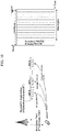
- FIG. 6 is a diagram illustrating a structure of a self-contained subframe according to one embodiment of the present invention.
- both a resource region for DL and a resource region for UL exist in one subframe.
- oblique line areas indicate downlink control regions and black colored areas indicate uplink control regions. Areas having no mark may be used for downlink data transmission or uplink data transmission.
- downlink (DL) transmission and uplink (UL) transmission are performed in due order within one subframe, whereby DL data may be transmitted and UL ACK/NACK may be received within one subframe.
- DL data may be transmitted and UL ACK/NACK may be received within one subframe.
- UL data may be transmitted and DL ACK/NACK may be received within one subframe.
- the expression "Self-Contained” may cover that a response (ACK/NACK) to DL or UL transmitted within the corresponding subframe is received within the corresponding subframe.
- the self-contained subframe will be defined as a subframe that may self-contain DL control information, DL/UL data and UL control information. That is, UL control information of Self-contained Subframe is not limited to HARQ-ACK information on DL data transmitted at the corresponding subframe.
- This self-contained subframe structure requires a time gap that allows an eNB and a UE to switch a transmission mode to a reception mode and vice versa. To this end, at least one OFDM symbol on which DL to UL switching is performed is set as a guard period (GP) in the self-contained subframe structure.
- GP guard period
- a subframe is configured in the order of DL control region-data region-UL control region
- the present invention is not limited thereto.
- a subframe may be configured in the order of DL control region-UL control region-data region.
- one subframe includes a total of 14 OFDM symbols, and one OFDM symbol is allocated to each of the DL control region and the UL control region. However, one or more OFDM symbols may be allocated to each of the DL control region and the UL control region. Similarly, the number of OFDM symbols included in one subframe may be changed.
- FIG. 7 is a diagram illustrating a DL subframe and a UL subframe according to one embodiment of the present invention.
- the GP is located at the time when DL is switched to UL.
- the GP is located between the DL data region and the UL control region at the DL subframe and is located between the DL control region and the UL data region at the UL subframe.
- the GP may include Tx/Rx switching time of the eNB/UE and a timing advance (TA) for UL transmission of the UE.
- TA timing advance
- a plurality of antenna elements may be installed in the same area. That is, a wavelength is 1cm in a band of 30GHz, and a total of 100 antenna elements of a 2D array may be arranged in a panel of 5 by 5 cm at an interval of 0.5 ⁇ (wavelength). Therefore, as a plurality of antenna elements are used, beamforming gain is enhanced, and coverage increase and/or throughput improvement is expected.
- TXRU transceiver unit
- a hybrid beamforming scheme for mapping a total of B TXRUs into a total of Q antenna elements may be considered.
- B ⁇ Q the number of beam directions that enable simultaneous transmission is limited to B or less.
- the New Rat (NR) system has an advantage in that beamforming gain can be obtained due to use of analog beams but has a disadvantage in that an analog beam can be formed only in one direction at each time instance (e.g., symbol, subframe, etc.). Since this restriction is imposed not only to transmission beamforming at a transmitter transmitting signals but also to transmission beamforming at a receiver receiving signals, performance may be degraded if a beam association between Tx and Rx beams is inaccurate.
- FIG. 8 illustrates an example of configuring Tx-Rx beams between a BS and a UE.
- a BS can be called a gNodeB (gNB).
- gNB gNodeB
- N Tx analog beams N Tx analog beams
- M Rx analog beams M Rx analog beams.
- the best reception performance can be achieved when the UE receives a signal carried by Tx beam #1 using Rx beam #1 or receives a signal carried by Tx beam #2 using Rx beam #2.
- the reception performance may be degraded, or the signal may not be detected.
- Tx-Rx beam combination e.g., best Tx-Rx beam
- transmission and reception loads are concentrated on the best beam, radio resources to be allocated per UE may become insufficient.
- processing delay similar to the conventional handover if beam switching is performed due to the channel variation, a method for reducing the number of rounds of beam switching or a method for simplifying a beam switching process is required.
- the present invention proposes a method in which a UE performs blind decoding for multiple Tx beams or multiple Tx-Rx beam combinations when attempting to decode a control channel. If a UE is configured to monitor multiple Tx beams or multiple Tx-Rx beams, control channel transmission is not necessarily limited to the best beam. Thus, the method has an advantage in that transmission and reception operation is more flexible in terms of the best beam change or beam switching.
- QCL could be interpreted as information used by a UE to configure an Rx beam.
- QCL can be called spatial QCL, and the spatial QCL means information used to configure an Rx beam for a specific resource. For example, if a specific control resource set (CORESET) and synchronization signal block #0 are in the (spatial) QCL relationship, a UE may receive resources in the corresponding CORESET using an Rx beam the UE uses when receiving synchronization signal block #0.
- CORESET specific control resource set
- synchronization signal block #0 a specific control resource set
- a UE may receive resources in the corresponding CORESET using an Rx beam the UE uses when receiving synchronization signal block #0.
- an Rx beam for a synchronization signal block may be different from an Rx beam included in the synchronization signal block.
- the UE may set an Rx beam for receiving a PBCH included in the synchronization signal block to be equal to an Rx beam used in receiving a PSS/SSS (e.g., SS beam #0), which is in the QCL relationship. If the UE select analog beams #0 (which corresponds to an analog beam at CSI-RS port #0) in the beam management process, the UE may receive an NR-PDCCH by assuming QCL with analog beam #0 in subsequent NR-PDCCH transmission.
- a Common Search Space (CSS) for a control channel may be configured in a synchronization signal block, and a User-specific Search Space (USS) for a control channel may be configured in each analog beam.
- reception operation is performed using an Rx beam used to receive a synchronization signal
- USS User-specific Search Space
- reception operation is performed using an Rx beam used to receive an analog beam selected in the beam management process (additionally, in the case of a USS transmitted via common signaling (e.g., CCE-to-REG mapping), it may be located in the same CORESET together with a CSS).
- the BS may change a Tx-Rx beam where the USS is configured to another one without changing or reconfiguring the CSS.
- a beam association can be referred to as a Tx-Rx beam pair, a Tx-Rx beam index combination, a best (Tx-Rx) beam, a Beam Pair Link (BPL), or the like.
- a network or UE may transmit indices of all Tx and Rx beams belonging to a Tx-Rx beam pair.
- the network or UE may indicate the beam association by transmitting an index of any one of the Tx and Rx beams.
- FIG. 8 assumes that the UE reports to the network a result of measuring Tx beam #1 through Rx beam #1 and a result of measuring Tx beam #2 through Rx beam #2. Thereafter, the network may intend to indicate the beam association of Tx beam #1 and Rx beam #1 in order to transmit control information using Tx beam #1. In this case, the network may signal both the index of Tx beam #1 and the index of Rx beam #1. However, even if the network signals any one of the two indices, the UE may know the beam association of Tx beam #1 and Rx beam #1. If the network signals Tx beam #1, the UE may attempt to receive the control information via Rx beam #1, which was used to measure and report Tx beam #1. Similarly, if the network signals Rx beam #1, the UE may attempt to receive the control information by assuming Tx beam #1, which was measured and reported through Rx beam #1.
- the UE may recognize that multiple beam associations (e.g., Rx beam #N - Tx Beam #K, Rx Beam #N - Tx Beam #L, etc.) are indicated.
- multiple beam associations e.g., Rx beam #N - Tx Beam #K, Rx Beam #N - Tx Beam #L, etc.
- a network can configure a known signal to which each beam is applied, for example, a Beam Reference Signal (BRS), a CSI-RS, a synchronization signal, etc. and transmit the known signal periodically (e.g., with a periodicity of 5 ms).
- a known signal can be classified as a signal related to initial access and a signal related to a CSI-RS configuration, which is received after the initial access.
- a CSI-RS corresponding to a synchronization signal block may be configured after the initial access.
- the UE may select BS's Tx beams suitable for the corresponding UE by performing measurement in a subframe in which such a signal as a BRS, a CSI-RS, etc. is transmitted. This may be called beam management.
- the UE may perform measurement using different Rx beams in multiple BRS subframes and then select a combination(s) of the eNB's Tx beams and the UE's Rx beams.
- the Tx-Rx beam association between the eNB and UE can be determined explicitly or implicitly. If the UE uses multiple RSs for the beam management, the UE may manage/report Tx-Rx beam pairs per RS. For example, Tx-Rx beam pairs obtained by measuring a synchronization signal block and Tx-Rx beam pairs obtained by measuring a CSI-RS may be separately reported. Alternatively, the network may request the UE to provide feedback of one of them. Further, the CSI-RS measurement result may always be preferentially reported. If no CSI-RS transmission is configured, synchronization signal block based beam measurement may be set as a default and reported.
- the method relates to beam measuring/reporting, and more particularly, to beam measurement/reporting and association, and it can be defined separately from beam association.
- the network may signal to the UE one or more multiple beam indices (e.g., Tx or Rx beam indices) or Tx-Rx beam index combinations where each UE should perform blind decoding for a control channel.
- the network may signal to the UE a subframe set for the signaled multiple beam indices or Tx-Rx beam index combinations (here, the subframe set may correspond to information on time resources where the UE should perform the blind decoding for the control channel by applying the corresponding Tx-Rx beam indices and, it can be represented on a subframe, slot, and or symbol basis.
- Each UE may perform blind decoding for a control channel in the signaled beam indices/index combinations and/or subframe set.
- the UE may perform the blind decoding on the assumption that there are Rx beams in all subframes based on the signaled beam indices/index combinations.
- Signaling the beam index combinations and subframe set to the UE could be interpreted to mean that the network signals to the UE Tx-Rx beam pairs and a resource set to be used by the UE in monitoring the corresponding beam pairs.
- the network may inform only beam indices. For example, a subframe set per beam or a beam index combination per subframe may be broadcast in advance. In other words, the resource set per beam may be signaled in advance, and information on beams the UE should monitor may be separately signaled.
- UE's preferred beams may be reported similar to the above-described (explicit) beam association.
- a subframe or a subframe set where a UE should perform blind decoding can be determined based on a beam association(s) reported by the UE and a subframe set per beam or beam indices per subframe, which are pre-signaled (i.e., broadcast/dedicatedly signaled) by a BS, without BS's beam association confirmation or allocation.
- the UE may assume that the BS performs transmission using the corresponding beam, i.e., Tx beam #0 and/or #3.
- the UE may perform blind decoding for a control channel in a subframe(s) corresponding to Tx beams #0 and #3 in the subframe set per beam, which is pre-signaled by the network.
- the network may signal a subframe set where the blind decoding can be performed for the best beams reported by the UE.
- (1) Network decision based method and (2) UE decision based method may be selectively used per Search Space (SS). For example, it is possible to determine a search space for a remaining system information (RMSI) control resource set (CORESET) by selecting the best beams (or beam association) based on (2) UE decision based method. On the other hand, it is possible to determine a USS by selecting the best beams (or beam association) based on (1) network decision based method.
- RMSI remaining system information
- CORESET control resource set
- RMSI may include, for example, information for UE's initial access (e.g., PRACH resource, etc.).
- an RMSI CORESET may mean a set of resources for transmitting the RMSI during a UE's initial access procedure.
- the search space may be configured in the CORESET.
- the CORESET is a set of resources for control signal transmission.
- a BS may signal information on the CORESET to a UE.
- the search space may be defined as a set of control channel candidates for which the UE performs blind detection.
- one search space may be defined in one CORESET.
- the CSS and USS may be defined in two CORESETs, respectively.
- multiple search spaces may be defined in one CORESET.
- the CSS and USS may be configured in the same CORESET.
- the UE may autonomously select the best beam for receiving system information such as RMSI, etc.
- the UE may search for the RMSI in an RMSI CORESET placed on the best beam selected by itself (in this case, the best beam may mean a synchronization signal block selected by the UE).
- each synchronization block may include a synchronization signal and a PBCH
- the PBCH may include information on the RMSI CORESET.
- the UE may assume that the RMSI CORESET indicated by the PBCH is transmitted via the same beam as the corresponding synchronization block.
- the UE may perform blind decoding for the corresponding CORESET by applying an Rx beam that is applied when the UE receives the corresponding synchronization block.
- the network may determine and signal a USS based on a UE's report. For example, if the best beams are determined based on a network's decision, the USS may be configured on the determined best beams.
- a hybrid method is available by combing (1) network decision based method and (2) UE decision based method. For example, if a UE reports its preferred beams to the network, the network may configure, for the UE, a sub-set or a full set for the reported preferred beams.
- Information on the subframe set per Tx beam or information on the beam indices supported per subframe set may pre-signaled (e.g., via MIB, SIB, RRC signaling, etc.).
- the information on the subframe set per Tx beam or the information on the beam indices supported per subframe set may be signaled with a predetermined periodicity (e.g., 20 ms, 40 ms, etc.) or through a PBCH every PBCH period.
- the network may provide multiple subframe sets for Tx-Rx beams to a UE through RRC signaling and then indicate activation/deactivation of the corresponding sets through a MAC control element (CE) or DCI.
- the activation/deactivation of the individual sets may be separately indicated through a bitmap, where multiple bits are mapped to the subframe sets, respectively, and the corresponding bitmap may be transmitted using the MAC CE.
- the UE may attempt control channel detection only in activated subframe sets by assuming that there is a Tx-Rx beam(s). On the contrary, the UE may assume that no control information is transmitted in deactivated subframe sets.
- the network configures Rx beams, the same method as the MAC CE can be used.
- the reliability mechanism may operate, for example, based on timing at which the corresponding DCI is transmitted or received, but the present invention is not limited thereto.
- the subframe set activation/deactivation information included in the DCI may be applied after elapse of a specific time (e.g., N subframes) from a subframe in which the UE receives the DCI.
- the purpose of the information on the subframe set per Tx beam or information on the beam indices supported per subframe is to indicate beam indices expected to be used by the network in a specific subframe, it is difficult for the network to change the beam configuration dynamically.
- an embodiment of the present invention proposes that a BS signals to a UE a Tx or Rx beam index (or Tx or Rx beam indices) the UE should assume in each subframe.
- the BS may designate an Rx beam(s) the UE should configure in each subframe.
- the network may signal, to the UE, a Tx beam(s) (or Rx beam(s)) the UE should assume instead of signaling a Tx beam(s) the network will actually use every time.
- UE's power consumption may increase because blind detection needs to be performed on more resources, but from the perspective of the network, it has an advantage in that beams can be dynamically changed.
- the network Since the network knows a Tx-Rx beam association(s) per subframe assumed when each UE performs blind decoding for a control channel, the network can flexibly change a Tx beam configuration to be actually used in a certain subframe.
- a UE may skip blind decoding in a subframe where its preferred Tx beam is not used, but the network cannot change a Tx beam configuration dynamically.
- the network may signal Tx beam indices the UE should assume in each subframe based on UE's reporting results.
- a Tx beam configuration and/or an Rx beam configuration such as subframe sets, etc. may be differently configured in each of the CSS and USS.
- transmission resources e.g., CSS or RMSI CORESET
- a UE can know a set (e.g., CSS or RMSI CORESET) that the UE should monitor to detect the system information based on the index of the synchronization signal block. This method can be applied to a UE-group SS.
- the network may signal a rough (coarse) direction of a beam in which a UE's USS is located or a subframe set or CORESET that a UE should monitor using an Rx beam in order to improve the flexibility of network scheduling.
- the network may signal the subframe set or CORESET using a control channel monitoring period, an offset, etc.
- the UE may receive either a parameter(s) for a Tx beam(s) or a parameter(s) for an Rx beam(s) among parameters for a Tx-Rx beam pair(s) in the corresponding CORESET or both of them.
- the best beam(s) a UE reports may be a measurement result obtained by assuming one Rx beam or a measurement result obtained by assuming multiple Rx beams.
- the network may configure information on Rx beam(s) that the UE should assume for measurement.
- the UE may perform measurement using all Rx beams but report only the three measurement results. Specifically, the UE selects an Rx beam used when measuring a Tx beam with the best measurement result among the measurement results. Thereafter, the UE may measure Tx beams using the corresponding Rx beam and then report Tx beams of which the measurement values are equal to or more than a threshold among the measured Tx beams. Similarly, the UE may bind Tx beams that can be received using the same Rx beam (for example, the Tx beams of which the measurement values are equal to or more than the threshold) and then report the bound Tx beams. This may include measuring and reporting per Rx beam and mean reporting one or multiple Tx beams that can be received per Rx beam.
- the measurement results reported by the UE may be greater than a specific threshold. For example, if among the 1st, 2nd, and 3rd best beams the UE measures using a specific Rx beam, only the 1st best beam is greater than the specific threshold, the UE may report only the 1st best beam.
- the specific threshold may be predefined or configured by the network.
- the network may request a UE to report measurement results on the assumption of multiple Rx beams.
- the UE may combine Tx beams with Rx beams the UE uses when measuring the corresponding Tx beams, respectively and then report the combinations in order of measurement.
- the UE may perform control channel blind decoding for multiple Tx beams.
- a method for enabling a UE to efficiently perform reception operation for multiple Tx beams will be described.
- an analog beam can be formed in a specific direction at a specific time (e.g., symbol, subframe) as described above.
- one or more analog beams may be formed at the same time according to capability such as the number of panels and the like. In case the number of beams to be formed is greater than capability, it is possible to set the number of beams corresponding to the capability to one unit and then form the beams at different times.
- the above restriction may be equally applied not only to Tx analog beams but to Rx analog beams.
- the UE may perform blind decoding only for one Tx beam per subframe.
- Example 1 Subframe-based Beam Selection
- an Rx beam(s) or a Tx beam(s) can be selected based on a subframe.
- a UE may attempt control channel decoding by applying a different Rx beam(s) to each subframe. For example, the UE may attempt the control channel decoding by assuming an Rx beam(s) suitable for a Tx beam(s) used in a specific subframe.
- the Tx beam(s) and/or Rx beam(s) the UE should assume may be determined based on the Tx-Rx beam association between the network and UE. If it is determined by the beam association that the UE should assume multiple beam combinations per subframe, the Tx-Rx beam combinations may be prioritized. That is, in one subframe, the UE may first perform blind decoding for a beam combination with the highest priority.
- the priority-based blind decoding method can be applied when a UE uses multiple Rx beams at the same time. For example, prioritization may be applied while the UE selects multiple Tx beams and/or Rx beams to perform control channel blind decoding.
- FIG. 9 illustrates an example of the subframe-based beam selection.
- FIG. 9 assumes that a UE attempt control channel decoding for three Tx-Rx beam combinations through coordination with a network.
- FIG. 9 represents a beam association by combining Tx and Rx beams, the beam association may be defined using Tx beams only.
- the beam association defined with only Tx beams can be applied when a UE reports its preferred beams.
- the UE may exclude an Rx beam the UE applies for a specific Tx beam when sending a report.
- FIG. 9 assumes that Tx beam indices used by the BS per subframe are transmitted through UE-dedicated signaling or broadcast. Also, it is assumed that transmission is performed using four Tx beams in each subframe.
- the network and UE determine the order of priority of the corresponding beam combinations as follows: ⁇ Tx beam #0 - Rx beam #1 ⁇ , ⁇ Tx beam #3 - Rx beam #2 ⁇ , ⁇ Tx beam #10 - Rx beam #3 ⁇ .
- the UE may assume that Tx beam #0 is used in subframe #0 based on the priority order per beam combination. Thus, the UE may attempt control channel blind decoding by applying Rx beam #1 in order to detect control information transmitted via Tx beam #0. Similarly, the UE may attempt control channel decoding by assuming ⁇ Tx beam #0, Rx beam #1 ⁇ , ⁇ Tx beam #3, Rx beam #2 ⁇ , and ⁇ Tx beam #10, Rx beam #3 ⁇ in subframe #1, subframe #J-1, and subframe #J, respectively.
- the UE may assume the Tx beam signaled by the network and then perform blind decoding by setting an Rx beam suitable for detecting the assumed Tx beam. If it is signaled that two Tx beams should be assumed in one subframe, the UE may perform the blind decoding by assuming one Tx beam with higher priority of the two Tx beams. Alternatively, if Rx beams associated with the two Tx beams are equal to each other, the UE may perform reception using the corresponding Rx beam.
- a CORESET may be configured per BPL or the multiple BPLs may be configured in one CORESET.
- a first CORESET for a first BPL may be configured in a first symbol(s) among multiple symbols in a subframe, and a second CORESET for a second BPL may be configured in a second symbol(s).
- the network may configure multiple control symbols in one subframe.
- a control symbol may mean a symbol where control information can be transmitted or a symbol where a CORESET is configured.
- the network may broadcast the number of control symbols or inform UEs in a cell of the number of control symbols through higher layer signaling. The provision of the number of control symbols performed by the network for the UEs could be interpreted to mean that time-domain resources in the CORESET are allocated.
- the number of control symbols may be signaled through a physical channel similar to a PCFICH.
- the network may inform the number of control symbols at each period or through aperiodic signaling.
- the network may allocate a different number of control symbols per subframe or per subframe set.
- the number of control symbols per subframe may mean the maximum number of control symbols for which a UE can perform blind decoding using different Rx beams in a corresponding subframe.
- a UE may perform blind decoding using a different Rx beam and/or Tx beam in each symbol.
- a different CORESET may be configured per symbol, and a different Tx beam and/or Rx beam may be configured per CORESET.
- one CORESET may be configured, and a different search space may be formed per symbol in the CORESET.
- the present example could be interpreted to mean that a search space corresponding a different Rx beam and/or Tx beam is configured in each control symbol.
- FIG. 10 illustrates an example of configuring control symbols according to an example of the present invention.
- the network may instruct a UE to perform PDCCH monitoring for different Tx beams.
- the network may configure different search spaces in different symbols in one CORESET and instruct a UE to perform PDCCH monitoring for different Tx beams based on the corresponding search spaces.
- each CORESET or search space may be defined in at least one symbol.
- FIG. 10 shows that difference search spaces are configured in the first and second symbols and a UE monitors a Tx beam with the first priority in the search space configured in the first symbol and a Tx beam with the second priority in the search space configured in the second symbol, this is merely an example and the present invention is not limited thereto.
- FIG. 10 can be interpreted as one of various examples of the present invention, where linkages between CORESETs or search spaces and Tx beams (or Tx-Rx associations) are configured by the network.
- FIG. 10 assumes that a network and a UE determine Tx beam #0 as the best beam and Tx beam #5 as the second best beam through the above-described beam association process and the network signals Tx beam indices per subframe in advance.
- the network signals to the UE that control information is to be transmitted in two control symbols in a corresponding subframe.
- the embodiment of the present invention can be applied when the beam association between the network and UE includes two or more beam combinations and/or when there are two or more control symbols.
- the first control symbol and the second control symbol may be set to a primary PDCCH (or primary CORESET) and a secondary PDCCH (or secondary CORESET), respectively.
- the primary and secondary PDCCHs may mean the order of priority of the best beams.
- the UE may independently configure different search spaces for different Tx beams in each of the control symbols and then perform blind decoding. For example, the UE may assume Tx beam #0 in subframe #0 and perform blind decoding for the primary PDCCH. In addition, the UE may assume Tx beam #5 in subframe #1 and perform blind decoding for the secondary PDCCH. Similarly, in subframe #J, the UE may perform the blind decoding for the primary PDCCH by assuming Tx beam #0 and perform the blind decoding for the secondary PDCCH by assuming Tx beam #5.
- the UE may configure a search space using two symbols on the assumption that Tx beam #0 is used for both of the primary and secondary PDCCHs.
- the network may signal a Tx beam(s) that should be assumed in each symbol.
- Example 2 since a UE is able to perform blind decoding for multiple Tx beams in one subframe, the UE can handle scheduling issues and beam switching more flexibly.
- the UE may configure an Rx beam(s) by assuming the Tx beam(s) that the network signals and perform blind decoding for a specific subframe. For example, if it is signaled that the UE should assume two Tx beams in one subframe, the UE may perform blind decoding for a Tx beam with higher priority on a primary PDCCH and perform blind decoding for a Tx beam with lower priority on a second PDCCH.
- FIG. 11 illustrates an example of Tx beams that a UE should assume to perform blind decoding.
- a network may signal a Tx beam(s) that the UE should assume to configure an Rx beam(s) and a search space(s) in each control symbol.
- the UE may configure a search space on the assumption that two control symbols have the same Tx beam.
- the UE may configure a search space using either a primary PDCCH or a secondary PDCCH based on the order of priority of Tx beams.
- the UE may assume that Tx-Rx beam pairs are applied in implicit order in each of the symbols.
- the application order of the Tx-Rx beam pairs may be signaled by the network to the UE or implicitly determined according to indices of the Tx-Rx beam pairs. If the network configures the application order of the Tx-Rx beam pairs for the UE, it could be interpreted to mean that the network configures a monitoring set for Tx beams in a symbol-based manner.
- the implicit decision of the application order of the Tx-Rx beam pairs may include determining symbol indices based on the order of priority of beams (e.g., primary beam, secondary beam, etc.).
- the 1 Rx beam case may mean that a UE uses an omni-direction Rx antenna or that some or all of the best beams reported by a UE are measured on the basis of one identical Rx beam.
- a network may instruct a UE to report multiple best beams under the restriction of one identical Rx beam.
- the UE may report the index of the Rx beam applied when measuring individual Tx beams or Tx beams measured by the same Rx beam among the measured Tx beams together.
- the UE may perform blind decoding by assuming one Tx beam for all control symbols. For example, from the perspective of the UE, since only one Rx beam is used even though a different Tx beam is configured in each symbol, the UE may perform the blind decoding by considering all symbols as one CORESET.
- a network may signal a Tx beam(s) that a UE should assume in each subframe.
- the UE may configure an Rx beam(s) by assuming the Tx beam(s) that the network signals and perform blind decoding. For example, if the UE receives signaling that the UE should assume two Tx beams in one subframe, the UE may separately configure a search space for each Tx beam and perform the blind decoding.
- the priority order of Tx beams may be determined based on UE's measurement results. For example, a beam having the best measurement result may have the highest priority.
- the UE may determine the number of control channel candidates included in a search space for each of the Tx beams based on the priority order.
- the UE may configure a search space for Tx beam #0 (i.e., a search space for a primary PDCCH) in a primary PDCCH symbol of SF #J and a search space for Tx beam #5 (i.e., a search space for a second PDCCH) in a secondary PDCCH symbol of SF #J.
- the number of control channel candidates allocated to the search space for the primary PDCCH may be more than that allocated to the search space for the second PDCCH.
- the primary PDCCH search space may be composed of N control channel candidates and the secondary PDCCH search space may be composed of M control channel candidates, where M is smaller than N.
- the primary PDCCH search space may be used for the purpose of blind detection of a Transmission Mode-dedicated (TM-dedicated) DCI format (e.g., DCI format 2C/2D in the LTE), and the secondary PDCCH search space may be used for the purpose of blind detection of a TM-common DCI format (e.g., a DCI format for fallback).
- TM-dedicated Transmission Mode-dedicated
- TM-common DCI format e.g., a DCI format for fallback
- a mapping relationship between beams and DCI formats can be defined.
- the beam corresponding to the primary PDCCH may be mapped to the TM-dedicated DCI format
- the beam corresponding to the secondary PDCCH may be mapped to the TM-common DCI format.
- different Tx beams may be configured depending on information the network desires to transmit. For example, blind decoding for DL assignment for transferring information on DL data transmission may be performed in the primary PDCCH search space, and blind decoding for a UL grant for transferring information on UL transmission may be performed in the secondary PDCCH search space.
- the embodiments of the present invention may be applied in order to transmit a control channel in CoMP mode.
- the CoMP operation between neighbor cells such as Dynamic transmission/reception Point Selection (DPS) or Joint Transmission (JT) may be performed for the control channel.
- a network may instruct a UE to perform blind decoding for Tx beams of each cell.
- the network may receive, from a UE, not only measurement results of a serving cell and/or beams of the serving cell but also measurement results of a neighbor cell and/or beams of the neighbor cell. Thereafter, based on the reported measurement results, the network may signal Tx beam indices per subframe and/or Tx beam indices the UE should assume in each subframe. In addition, information on each Tx beam may be signaled together. For example, quasi co-location (QCL) information that the UE should assume when performing decoding for a corresponding Tx beam and information on a cell transmitting the corresponding Tx beam (e.g., cell ID, virtual cell ID, etc.) may be signaled together.
- QCL quasi co-location
- a different CORESET may be configured for each Tx beam, and a different monitoring set and different QCL may be assumed for each CORESET.
- the network may associate multiple CSI-RS ports with the serving and neighboring cells and signal QCL with different CSI-RS ports in each CORESET.
- the transmission from the multiple cells may be indicated by independent signaling.
- the network may signal Tx beam indices per subframe for the serving cell or Tx beam indices that the UE should assume in each subframe in the same manner as described above and indicate multiple beam observation considering the neighbor cell's beams, using additional RRC signaling or DCI in the previous subframe.
- the network may transmit to a UE which one of single cell operation, DPS, JT, and repeated transmission is used for control channel transmission.
- a control channel is repeated, information on the repeated transmission may be defined or signaled in advance. For example, if a UE needs to perform blind decoding for multiple beams in one subframe as shown in SF #N of FIG. 11 , the network may signal to the UE that a control channel will be repeated. Specifically, the network may define/signal in advance that the repetition is performed on the same control channel candidate index in each control symbol or Tx beam or that the repetition is performed based on an index offset between control channel candidates of the primary and second PDCCHs. This could be interpreted as a transmit diversity scheme using different analog beams.
- different CORESETs may be defined in different symbols of one subframe, and the network may transmit the same control information in the different CORESETs.
- the same control information e.g., PDCCH
- PDCCH Physical Downlink Control Channel
- a UE measures a synchronization signal, a PBCH DMRS, or a designated CSI-RS (e.g., a CSI-RS for beam management) and performs reporting (e.g., a preferred beam, a strong beam list, etc.) based on the measurement results.
- BPL Beam Pair Link
- the UE may obtain the BPL.
- the monitoring set may be defined in the time domain together with the subframe set, slot set, or symbol set, but the present invention is not limited thereto. That is, the monitoring set may be defined together with an RB set in the frequency domain. Further, the monitoring set may be defined in the time-frequency domain.
- each UE may be configured with a CORESET to perform blind decoding for a control channel.
- the CORESET may mean a resource region for designating a search space to be used by a UE when performing blind decoding for a control channel.
- a CORESET configuration may include information for performing blind decoding in a corresponding CORESET such as time/frequency resources for designating a CORESET region in one slot, resources where the corresponding CORESET should be monitored (e.g., a monitoring set, a slot, a subframe, a symbol, or sets thereof), Control Channel Element-to-Resource Element Group (CCE-to-REG) mapping that should be assumed in the corresponding CORESET, PDCCH-to-CCE mapping, search spaces, RS configurations, REG bundle parameters, etc.
- CCE-to-REG Control Channel Element-to-Resource Element Group
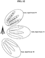
- FIG. 12 illustrates an example of a beam configuration in a network performing multiple beam observation.
- FIG. 12 assumes that a BS has multiple panels and a different analog beam can be implemented in each panel.
- a Synchronization Signal (SS) beam may mean a beam corresponding to coverage of each SS block in the initial access procedure.
- SS Synchronization Signal
- individual analog beams formed in an SS block may be simultaneously transmitted via the panels.
- a UE may recognize that one SS beam is received within SS coverage.
- the SS beam may become equal to the analog beam.
- An SS beam may be called an SS block.
- the UE performs measurement for each SS beam and then selects a specific SS beam. After selecting the SS beam, the UE may decode a Physical Broadcast Channel (PBCH) associated with the corresponding SS beam and calculate a CSS for detecting RMSI or a CORESET including the corresponding CSS based on the PBCH information.
- PBCH Physical Broadcast Channel
- the RMSI may be regarded as a set of some of the SI in the legacy LTE, which is necessary for initial access.
- the UE may assume that the 'CORESET or CSS for the RMSI' is QCLed with the 'SS, PBCH, and/or PBCH DMRS'.
- the UE may assume that a tracking RS or a wideband control channel DMRS is QCLed with the SS block.
- the UE may additionally receive a QCL relationship between the CORESET or CSS for the RMSI and a CSI-RS.
- the QCL may be configured between the 'CORESET or CSS for the RMSI transmission' and the 'SS block, tracking RS, wideband RS and/or CSI-RS'.
- the UE may receive the CSI-RS associated with the SS block in a process after the initial access. By doing so, the QCL between the SS block and CSI-RS may be established for operations after the initial access.
- the UE may receive a CSI-RS configuration from the network for analog beam selection. Based on the CSI-RS measurement/report, the UE may receive at least one association (i.e., BPL) between network's Tx beams and UE's Rx beams.
- BPL association
- An SS beam may be QCLed with an SS block, or it may mean a beam associated with a CSI-RS equivalent to the SS block.
- an analog beam may mean a beam associated with a CSI-RS configured by a network for the purpose of beam management and the like.
- a CSS may imply a CORESET in which the CSS is configured
- a USS may mean a CORESET in which the USS is configured.
- the USS and CSS may have different QCL configurations.
- the USS and CSS may be QCLed with different CSI-RS ports, respectively.
- the USS may be QCLed with a CSI-RS
- the CSS may be QCLed with an SS block. This could be interpreted to mean that in the USS, a UE performs reception using an RX beam used when the UE receives a specific CSI-RS, and in the CSS, a UE performs reception using an Rx beam used when the UE receives an SS block.
- an RRC-connected UE may receive CORESETs for the CSS and USS via RRC signaling.
- the USS may be configured per analog beam in consideration of a channel state between a network and a UE.
- the USS may be configured in each BPL.
- the CSS since multiple UEs can monitor the CSS, it is desirable that the CSS is configured per SS beam.
- a UE may be out of analog beam coverage due to its mobility, and in this case, the UE may fail to decode UE-specific DCI.
- fallback operation is required. The fallback operation may be performed based on the CSS. That is, it is desirable to secure coverage wider than the USS (or it is desirable to perform transmission via a beam wider than the USS).
- the resource region of the CSS, where the fallback operation is to be performed may vary per analog beam.
- the UE may need to monitor the CSS in different CORESETs in order to perform the fallback operation. More particularly, assuming that a UE is configured with analog beam "a" belonging to SS beam #0 and analog beam "b" belonging to SS beam #1 in FIG. 12 , the UE may perform the fallback operation for analog beam "a" in the CSS associated with SS beam #0 and perform the fallback operation for analog beam "b" in the CSS associated with SS beam #1.
- the purpose of the CSS is not limited to the fallback operation but includes transmitting common control information for the NR system.
- a UE may perform blind decoding for multiple CSSs which are QCLed with different SS blocks, respectively.
- the UE may perform fallback operation for one of the USSs that the UE should monitor in another CSS.
- a CSS where fallback operation for a corresponding USS is to be performed may be differently configured.
- a CSS or BPL where fallback operation for a USS(s) belonging to a corresponding BPL may be configured.
- different monitoring sets may be configured for CSSs, and a monitoring set for each CSS may be determined independently from that for a USS associated with a corresponding CSS.
- the present invention does not exclude that different USSs use one identical CSS for the fallback operation.
- each BPL configuration may include a CSS associated with each BPL or a monitoring set for a CORESET for configuring the CSS.
- CSS CORESET information associated with each USS's CORESET may be given.
- a BPL may be configured independently per CORESET, and a UE may receive a BPL configuration according to a network's CORESET configuration.
- an SS beam may be identical to an analog beam.
- the network may inform each UE of a relationship between the USS and CSS.
- each UE may be provided the following information through RRC signaling: whether the USS and CSS coexist in one CORESET; a monitoring set of the CORESET for the USS/CSS; resource allocation of the CORESET for the USS/CSS; and/or whether there is a pairing between the USS(s) and CSS.
- the UE may configure an Rx beam(s) based on a BPL associated with the CSS.
- the network may designate an Rx beam(s). For example, if multiple analog beams are included in one SS block, the UE may consider an Rx beam optimized for an SS block to which an analog beam associated with the USS belongs as an Rx beam for decoding the CSS.
- the UE may also perform SS block measurement. In this case, the UE may select an Rx beam to be used for CSS decoding based on information of a serving SS block the UE updates most recently. If an Rx beam used in the associated USS is used as an Rx beam for the CSS or if the SS block measurement is performed, it may be configured based on the measurement result of the SS block.
- a CSS or a CORESET for setting the CSS may be configured only for a BPL with high priority for the purpose of complexity reduction. For example, if an SS block including a Tx beam corresponding to a serving BPL is associated with Rx beam #1, a UE may perform blind detection for the CSS using Rx beam #1.
- the configuration of the primary BPL may include information on a CORESET for the CSS, information on a monitoring set, etc.
- the UE may consider such a BPL configuration. For example, if two CORESETs or search spaces for two different BPL pairs, and more particularly, two different BPL pairs having different Rx beams are configured on the same resources, the UE may assume that the two CORESETs are prioritized. Moreover, if the CSS and USS overlap with each other, the UE may assume that the CSS has higher priority. Further, if two USSs overlap with each other, the two USSs may be prioritized based on measurement results, CORESET indices, or the number of rounds of blind detection.
- the UE may assume that for a CORESET or search space to which the corresponding Rx beam is applied, no REG/CCE is mapped to the entire OFDM symbol. If multi-symbol duration is configured, overall duration can decrease.
- the UE may perform blind detection for the two search spaces using an Rx beam for a search space with higher priority. And, the UE may adopt the configuration of the higher-priority search space on the resources where the Rx beams overlap. In this case, the UE may determine whether to perform rate-matching or whether to adopt the configuration of the higher-priority search space as follows.
- a network may sweep possible beams and create a list of UEs that the network can serve per beam based on a UE's measurement report on a corresponding beam.
- the network may determine a resource region (e.g., a subframe set, a slot set, or a symbol set) where each Tx beam is used based on the list and then inform the UEs of the determined resource region.
- a resource region e.g., a subframe set, a slot set, or a symbol set
- operation per beam is described based on a slot, but the operation per beam can also be defined on a subframe or symbol basis.
- a UE performs blind decoding for all slots, it may increase UE's power consumption.
- the UE uses an inappropriate Rx beam, its reception performance may be degraded due to a low SINR and the like.
- the UE needs to perform reception using an appropriate Rx beam in a proper slot based on BPL information, which is delivered from the network.
- a CORESET configuration received by the UE is different from a resource to which each BPL is applied, the UE may perform unnecessary operations or malfunction. Thus, it is desirable to match a monitoring set to which each BPL is applied with a monitoring set where blind decoding for each CORESET should be performed.
- a BPL may mean a linkage between a network's Tx beam(s) and a UE's Rx beam(s).
- BPL information may be signaled such that resources for the Tx and Rx beams are indicated in a UE-specific manner.
- the BPL information may be transmitted such that a Tx beam (set) that the UE should monitor is signaled in a UE-specific manner based on the network's Tx beam(s), which is previously indicated as common or group-common information, and resources used for the corresponding Tx beam(s).
- the BPL could be interpreted as a QCL assumption related to beam selection.
- the network may configure a CORESET per BPL and transmit relevant information to the UE through higher layer signaling, a MAC CE, or the like. For example, only one BPL may be assumed in one CORESET, and only one QCL assumption may be applied to the corresponding CORESET. To this end, the network may configure, for each UE, a monitoring set per BPL and multiple CORESETs (e.g., localized/distributed) for a corresponding BPL. In addition, the network may configure a CORESET monitoring set for each CORESET.
- the BPL can be signaled in the form of a Tx beam(s), an Rx beam(s), a Tx-Rx beam combination, etc. When the BPL is signaled as the Tx beam(s), the UE may monitor resources to which the corresponding BPL is applied using an Rx beam that shows the best reception performance with respect to the corresponding Tx beams(s).
- a CORESET monitoring set may be assumed to be a subset of a corresponding BPL monitoring set.
- the UE may assume a BPL monitoring set as a monitoring set of a corresponding CORESET.
- a CORESET for the use of a fallback for UE-specific control signaling and a CORESET for configuring the CSS where common control information is transmitted may be configured per BPL as proposed above.
- a monitoring set for the CORESET for configuring the CSS may not belong to the corresponding BPL monitoring set.
- the CSS or CORESET for the CSS and the USS may be defined in different BPLs.
- different QCL assumptions may be configured for the CSS or CORESET for the CSS and the USS, respectively.
- a BPL may be configured on an Rx beam basis.
- a CORESET(s) may be configured per Rx beam that the UE can use, and configurations such as a monitoring set may be signaled per CORESET.
- a BPL to which a corresponding CORESET is applied may be configured per CORESET.
- a monitoring set for each BPL may be replaced with a CORESET monitoring set.
- Each CORESET may include a search space type supported by a corresponding CORESET.
- the number thereof may be determined according to the number of UE's BPLs.
- some of the multiple CORESETs may be equal to each other. This is because when a BPL is formed with respect to multiple analog beams belonging to one SS block, the corresponding analog beams need to use the same CSS for the fallback operation.
- Example A and B if a BPL configuration/update period does not match with a CORESET configuration/update period, the network should repeatedly transmit all information whenever signaling BPL/CORESET configurations.
- the network may independently signal the BPL configuration and the CORESET configuration and provide an assumption for eliminating an ambiguity that may occur.
- a UE monitors resources that are not its own BPL, it may increase UE's power consumption, and thus the UE needs to perform reception in a BPL monitoring set. This could be equally applied to a CORESET monitoring set. Eventually, the UE may perform monitoring for a PDCCH in a region where the BPL monitoring set and the CORESET monitoring set overlap.
- multiple BPL monitoring sets may be configured in each BPL, and similarly, multiple CORESET monitoring sets may also be configured.
- the network may include information on a CORESET(s) capable of monitoring a corresponding BPL in the BPL configuration or include information on a BPL to which a corresponding CORESET should be applied in the CORESET configuration.
- the UE may monitor the CORESET for the CSS even though the CORESET for the CSS does not overlap with the BPL monitoring set. If the network transmits common control information via different Tx beams, the UE may increase the probability of receiving the common control information by increasing the number of monitoring rounds.
- the BPL and CORESET can be reconfigured as follows.
- the CORESET may be configured per BPL, and activation/deactivation may be configured per CORESET.
- the CORESET per BPL should be separately configured in each Bandwidth Part (BP).
- BP Bandwidth Part
- all the basic information of the CORESET may be composed of configuration building blocks, and the network may signal the indices of a plurality of building blocks.
- monitoring intervals may be configured separately from frequency information.
- the network may configure multiple pieces of REG-CCE mapping, TxD, duration, etc. and then include one of them in each CORESET.
- the network may separately configure the BPL information and configure BPLs to be mapped to individual CORESETs.
- the network may change the CORESET/BPL in a similar manner to the scheme for BP adaptation/activation.
- NR-PDCCH transmission should be robust to BPL blocking, and a UE may be configured to monitor NR-PDCCHs in multiple BPLs at the same time. Also, the UE may be configured to monitor NR-PDCCHs in different BPLs of different NR-PDCCH symbols.
- parameters related to a UE's Rx beam configuration may be set through higher layer signaling or a MAC CE, and the corresponding parameters should be considered in designing a search space.
- a Spatial QCL assumption between DMRS antenna ports for demodulation of a DL control channel and DL RS antenna ports may be indicated to receive the DL control channel.
- a QCL configuration for a UE-specific NR-PDCCH may be provided by means of RRC or MAC CE signaling.
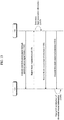
- FIG. 13 is a flowchart illustrating a method of transmitting and receiving downlink control information between a BS and a UE according to an embodiment of the present invention. Redundant descriptions will be omitted herein.
- the UE receives a synchronization signal through a synchronization signal block from the BS [1305]. By receiving the synchronization signal, the UE may establish downlink synchronization with the BS. Additionally, a random-access procedure (not shown) may be performed for uplink synchronization.
- the UE measures BS's multiple Transmission (Tx) beams using at least one Reception (Rx) beam and then report measurement results to the BS [1310].
- Tx multiple Transmission
- Rx Reception
- the BS determines beam association information between UE's Rx beams and BS's Tx beams based on the UE's beam measurement report [1315].
- the beam association information indicates at least two beam pairs, where the UE's Rx beam and the BS's Tx beams are associated with each other.
- the beam association information may include a beam index of one of Tx and Rx beams belonging to each beam pair or include indices of both the Tx and Rx beams.
- the UE receives the beam association information from the BS [1320].
- the BS transmits downlink control information based on the beam association information [1325], and the UE attempts blind detection of a physical downlink control channel carrying the downlink control information based on the beam association information [1330].
- the UE may configure a Rx beam(s) to be used for the blind detection of the physical downlink control channel according to the two or more beams indicated by the beam association information. For example, the UE may attempt the blind detection of the physical downlink control channel by configuring different Rx beams for the at least two beam pairs, respectively.
- the at least two beam pairs may be configured in different symbols within the same subframe, respectively.
- the UE may receive, from the BS, information regarding at least one of control resource sets (CORESETs) where the at least two beam pairs are configured respectively and monitoring sets where the UE should monitor the at least two beam pairs respectively.
- CORESETs control resource sets
- the UE may apply different Quasi Co-Location (QCL) assumptions to the CORESETs, respectively. For example, the UE may assume that the CORESETs are Quasi Co-Located (QCLed) with different Channel State Information-Reference Signals (CSI-RSs), respectively. As another example, the UE may assume that among the CORESETs, a first CORESET for UE-specific control information is QCLed with a CSI-RS and a second CORESET for common control information is QCLed with the synchronization signal block.
- QCL Quasi Co-Location
- FIG. 14 is a block diagram for configurations of a base station 105 and a user equipment 110 in a wireless communication system 100.
- the wireless communication system 100 may include at least one base station and/or at least one user equipment.
- a base station 105 may include a transmitted (Tx) data processor 115, a symbol modulator 120, a transmitter 125, a transceiving antenna 130, a processor 180, a memory 185, a receiver 190, a symbol demodulator 195 and a received data processor 197.
- a user equipment 110 may include a transmitted (Tx) data processor 165, a symbol modulator 170, a transmitter 175, a transceiving antenna 135, a processor 155, a memory 160, a receiver 140, a symbol demodulator 155 and a received data processor 150.
- the base station/user equipment 105/110 includes one antenna 130/135 in the drawing, each of the base station 105 and the user equipment 110 includes a plurality of antennas.
- each of the base station 105 and the user equipment 110 of the present invention supports an MIMO (multiple input multiple output) system.
- the base station 105 according to the present invention may support both SU-MIMO (single user-MIMO) and MU-MIMO (multi user-MIMO) systems.
- the transmission data processor 115 receives traffic data, codes the received traffic data by formatting the received traffic data, interleaves the coded traffic data, modulates (or symbol maps) the interleaved data, and then provides modulated symbols (data symbols).
- the symbol modulator 120 provides a stream of symbols by receiving and processing the data symbols and pilot symbols.
- the symbol modulator 120 multiplexes the data and pilot symbols together and then transmits the multiplexed symbols to the transmitter 125.
- each of the transmitted symbols may include the data symbol, the pilot symbol or a signal value of zero.
- pilot symbols may be contiguously transmitted.
- the pilot symbols may include symbols of frequency division multiplexing (FDM), orthogonal frequency division multiplexing (OFDM), or code division multiplexing (CDM).
- the transmitter 125 receives the stream of the symbols, converts the received stream to at least one or more analog signals, additionally adjusts the analog signals (e.g., amplification, filtering, frequency upconverting), and then generates a downlink signal suitable for a transmission on a radio channel. Subsequently, the downlink signal is transmitted to the user equipment via the antenna 130.
- analog signals e.g., amplification, filtering, frequency upconverting
- the receiving antenna 135 receives the downlink signal from the base station and then provides the received signal to the receiver 140.
- the receiver 140 adjusts the received signal (e.g., filtering, amplification and frequency downconverting), digitizes the adjusted signal, and then obtains samples.
- the symbol demodulator 145 demodulates the received pilot symbols and then provides them to the processor 155 for channel estimation.
- the symbol demodulator 145 receives a frequency response estimated value for downlink from the processor 155, performs data demodulation on the received data symbols, obtains data symbol estimated values (i.e., estimated values of the transmitted data symbols), and then provides the data symbols estimated values to the received (Rx) data processor 150.
- the received data processor 150 reconstructs the transmitted traffic data by performing demodulation (i.e., symbol demapping, deinterleaving and decoding) on the data symbol estimated values.
- the processing by the symbol demodulator 145 and the processing by the received data processor 150 are complementary to the processing by the symbol modulator 120 and the processing by the transmission data processor 115 in the base station 105, respectively.
- the transmission data processor 165 processes the traffic data and then provides data symbols.
- the symbol modulator 170 receives the data symbols, multiplexes the received data symbols, performs modulation on the multiplexed symbols, and then provides a stream of the symbols to the transmitter 175.
- the transmitter 175 receives the stream of the symbols, processes the received stream, and generates an uplink signal. This uplink signal is then transmitted to the base station 105 via the antenna 135.
- the uplink signal is received from the user equipment 110 via the antenna 130.
- the receiver 190 processes the received uplink signal and then obtains samples.
- the symbol demodulator 195 processes the samples and then provides pilot symbols received in uplink and a data symbol estimated value.
- the received data processor 197 processes the data symbol estimated value and then reconstructs the traffic data transmitted from the user equipment 110.
- the processor 155/180 of the user equipment/base station 110/105 directs operations (e.g., control, adjustment, management, etc.) of the user equipment/base station 110/105.
- the processor 155/180 may be connected to the memory unit 160/185 configured to store program codes and data.
- the memory 160/185 is connected to the processor 155/180 to store operating systems, applications and general files.
- the processor 155/180 may be called one of a controller, a microcontroller, a microprocessor, a microcomputer and the like. And, the processor 155/180 may be implemented using hardware, firmware, software and/or any combinations thereof. In the implementation by hardware, the processor 155/180 may be provided with such a device configured to implement the present invention as ASICs (application specific integrated circuits), DSPs (digital signal processors), DSPDs (digital signal processing devices), PLDs (programmable logic devices), FPGAs (field programmable gate arrays), and the like.
- ASICs application specific integrated circuits
- DSPs digital signal processors
- DSPDs digital signal processing devices
- PLDs programmable logic devices
- FPGAs field programmable gate arrays
- the firmware or software may be configured to include modules, procedures, and/or functions for performing the above-explained functions or operations of the present invention. And, the firmware or software configured to implement the present invention is loaded in the processor 155/180 or saved in the memory 160/185 to be driven by the processor 155/180.
- Layers of a radio protocol between a user equipment/base station and a wireless communication system may be classified into 1st layer LI, 2nd layer L2 and 3rd layer L3 based on 3 lower layers of OSI (open system interconnection) model well known to communication systems.
- a physical layer belongs to the 1st layer and provides an information transfer service via a physical channel.
- RRC (radio resource control) layer belongs to the 3rd layer and provides control radio resourced between UE and network.
- a user equipment and a base station may be able to exchange RRC messages with each other through a wireless communication network and RRC layers.
Landscapes
- Engineering & Computer Science (AREA)
- Signal Processing (AREA)
- Computer Networks & Wireless Communication (AREA)
- Power Engineering (AREA)
- Mobile Radio Communication Systems (AREA)
Applications Claiming Priority (3)
| Application Number | Priority Date | Filing Date | Title |
|---|---|---|---|
| US201662364884P | 2016-07-21 | 2016-07-21 | |
| US201762520579P | 2017-06-16 | 2017-06-16 | |
| PCT/KR2017/007869 WO2018016907A1 (ko) | 2016-07-21 | 2017-07-21 | 무선 통신 시스템에서 하향링크 제어 정보를 송신 또는 수신하는 방법 및 이를 위한 장치 |
Publications (3)
| Publication Number | Publication Date |
|---|---|
| EP3490184A1 true EP3490184A1 (de) | 2019-05-29 |
| EP3490184A4 EP3490184A4 (de) | 2020-02-26 |
| EP3490184B1 EP3490184B1 (de) | 2023-05-31 |
Family
ID=60993170
Family Applications (1)
| Application Number | Title | Priority Date | Filing Date |
|---|---|---|---|
| EP17831379.7A Active EP3490184B1 (de) | 2016-07-21 | 2017-07-21 | Verfahren zum senden oder empfangen von abwärtsstreckensteuerinformationen in einem drahtloskommunikationssystem und vorrichtung dafür |
Country Status (4)
| Country | Link |
|---|---|
| US (1) | US10638484B2 (de) |
| EP (1) | EP3490184B1 (de) |
| CN (1) | CN109565390B (de) |
| WO (1) | WO2018016907A1 (de) |
Cited By (10)
| Publication number | Priority date | Publication date | Assignee | Title |
|---|---|---|---|---|
| KR20190101472A (ko) * | 2017-01-09 | 2019-08-30 | 후아웨이 테크놀러지 컴퍼니 리미티드 | 무선 통신 방법, 단말 장치, 및 네트워크 장치 |
| EP3629645A4 (de) * | 2018-05-09 | 2020-10-14 | LG Electronics Inc. | Verfahren zur überwachung eines steuerkanals durch ein endgerät in einem drahtlosen kommunikationssystem und endgerät mit diesem verfahren |
| WO2021008430A1 (zh) * | 2019-07-15 | 2021-01-21 | 维沃移动通信有限公司 | 传输方法和通信设备 |
| EP3579602A4 (de) * | 2017-02-03 | 2021-03-17 | Ntt Docomo, Inc. | Benutzerendgerät und drahtloskommunikationsverfahren |
| EP3860296A4 (de) * | 2018-09-28 | 2021-11-24 | Datang Mobile Communications Equipment Co., Ltd. | Verfahren zur übertragung von downlink-steuerkanälen, endgerät und netzwerkseitige vorrichtung |
| EP3917256A4 (de) * | 2019-02-15 | 2022-03-30 | Huawei Technologies Co., Ltd. | Verfahren zur übertragung auf der basis von multi-downlink-steuerinformationen, vorrichtung, system und speichermedium |
| WO2022086256A1 (en) | 2020-10-23 | 2022-04-28 | Samsung Electronics Co., Ltd. | Method and device for repetitive transmission/reception of downlink control information in wireless communication system |
| US11378331B2 (en) | 2017-12-06 | 2022-07-05 | Lg Electronics Inc. | Refrigerator and out plate for refrigerator door |
| EP4013156A4 (de) * | 2019-08-16 | 2022-10-19 | Huawei Technologies Co., Ltd. | Kommunikationsverfahren und -vorrichtung sowie speichermedium |
| EP4145716A1 (de) * | 2021-09-02 | 2023-03-08 | Apple Inc. | Erfassen von systeminformationen basierend auf mehreren strahlen |
Families Citing this family (83)
| Publication number | Priority date | Publication date | Assignee | Title |
|---|---|---|---|---|
| WO2018021865A1 (ko) * | 2016-07-29 | 2018-02-01 | 엘지전자 주식회사 | 무선 통신 시스템에서 단말의 채널 상태 정보 보고 방법 및 이를 지원하는 장치 |
| US10924317B2 (en) * | 2016-11-03 | 2021-02-16 | Lg Electronics Inc. | Method for transmitting or receiving downlink control information in wireless communication system, and device therefor |
| US11304190B2 (en) * | 2016-11-08 | 2022-04-12 | Qualcomm Incorporated | Search space design and use |
| AU2016431911B2 (en) | 2016-12-08 | 2022-02-10 | Guangdong Oppo Mobile Telecommunications Corp., Ltd. | Method and apparatus for wireless communication |
| WO2018124027A1 (ja) * | 2016-12-27 | 2018-07-05 | 株式会社Nttドコモ | ユーザ端末及び無線通信方法 |
| US11523376B2 (en) * | 2017-01-05 | 2022-12-06 | Huawei Technologies Co., Ltd. | Method for downlink control channel design |
| CN110089169B (zh) * | 2017-01-05 | 2020-11-03 | Oppo广东移动通信有限公司 | 一种信令传输方法及设备 |
| US10523476B2 (en) * | 2017-01-11 | 2019-12-31 | Qualcomm Incorporated | Signal scrambling sequence techniques for wireless communications |
| US10334515B2 (en) | 2017-01-13 | 2019-06-25 | ENK Wireless, Inc. | Conveying information via auxiliary device selection |
| US10432441B2 (en) * | 2017-02-06 | 2019-10-01 | Samsung Electronics Co., Ltd. | Transmission structures and formats for DL control channels |
| WO2018170625A1 (zh) * | 2017-03-18 | 2018-09-27 | 南通朗恒通信技术有限公司 | 一种基站、用户设备中的用于多天线传输的方法和装置 |
| CN108631889A (zh) * | 2017-03-22 | 2018-10-09 | 株式会社Ntt都科摩 | 无线链路失败检测方法和用户设备 |
| CN108633045A (zh) * | 2017-03-24 | 2018-10-09 | 华为技术有限公司 | 一种链路重建方法及设备 |
| US10897753B2 (en) * | 2017-05-04 | 2021-01-19 | Sharp Kabushiki Kaisha | Systems and methods for supporting multiple allocations in UL/DL grant for a 5G NR UE and gNB |
| US10912111B2 (en) * | 2017-05-04 | 2021-02-02 | Samsung Electronics Co., Ltd. | Method and apparatus for transmitting remaining minimum system information in multibeam-based system |
| KR102435618B1 (ko) * | 2017-06-15 | 2022-08-24 | 삼성전자주식회사 | 무선 통신 시스템에서 하향링크 제어 채널을 송신하기 위한 장치 및 방법 |
| US11159294B2 (en) * | 2017-08-04 | 2021-10-26 | Beijing Xiaomi Mobile Software Co., Ltd. | Method for obtaining time-frequency resource position of common control resource set of remaining system information |
| CN111095846B (zh) | 2017-08-08 | 2023-04-28 | 苹果公司 | 用于复用跟踪参考信号和同步信号块的系统和方法 |
| CN109392119B (zh) | 2017-08-10 | 2020-02-18 | 维沃移动通信有限公司 | 空间特性参数集合指示方法、用户侧设备和网络侧设备 |
| CN109392144B (zh) * | 2017-08-11 | 2023-10-03 | 华为技术有限公司 | 通信方法和通信设备 |
| CN113890706B (zh) * | 2017-08-11 | 2022-09-09 | 华为技术有限公司 | 一种信息发送、接收方法及装置 |
| CN109474384B (zh) | 2017-09-08 | 2021-02-12 | 华为技术有限公司 | 通信方法、终端设备和网络设备 |
| CN109511169B (zh) * | 2017-09-15 | 2024-01-05 | 华为技术有限公司 | 一种控制资源集合的获取方法、装置以及系统 |
| US10123322B1 (en) | 2017-09-18 | 2018-11-06 | Qualcomm Incorporated | Transmission of beam switch commands through control channel signaling |
| CN112204910B (zh) * | 2017-10-02 | 2024-05-17 | 联想(新加坡)私人有限公司 | 确定寻呼时机资源 |
| KR102581454B1 (ko) * | 2017-11-10 | 2023-09-22 | 삼성전자주식회사 | 무선 통신 시스템에서 제어 정보를 송수신하는 방법 및 장치 |
| CN111527722B (zh) * | 2017-11-14 | 2023-05-02 | 交互数字专利控股公司 | 用于物理下行链路控制信道(pdcch)候选确定的方法 |
| CN109802808A (zh) * | 2017-11-17 | 2019-05-24 | 电信科学技术研究院 | 一种同步块与寻呼调度信令关联方法、指示方法及装置 |
| US10778306B2 (en) * | 2017-11-17 | 2020-09-15 | Qualcomm Incorporated | Methods for beam determination after beam pair link indication |
| US11457472B2 (en) * | 2017-12-18 | 2022-09-27 | Samsung Electronics Co., Ltd. | Method and apparatus for initial access block on stand-alone NR unlicensed spectrum |
| US10660020B2 (en) * | 2017-12-20 | 2020-05-19 | Qualcomm Incorporated | Search space set combining and dropping |
| CN110034844B (zh) * | 2018-01-12 | 2021-03-09 | 电信科学技术研究院有限公司 | 一种信息传输方法、装置、第一设备及第二设备 |
| WO2019144388A1 (zh) * | 2018-01-26 | 2019-08-01 | 北京小米移动软件有限公司 | 信息指示方法及装置、基站和用户设备 |
| BR112020014813A2 (pt) * | 2018-01-26 | 2020-12-08 | Beijing Xiaomi Mobile Software Co., Ltd. | Método e meio de armazenamento para configurar informação, equipamento de usuário, método e meio de armazenamento para determinar posição de tempo e frequência, e estação base |
| CN113364570B (zh) * | 2018-02-08 | 2023-06-23 | 展讯通信(上海)有限公司 | 下行控制信息的检测方法、装置及用户设备 |
| US20190253904A1 (en) * | 2018-02-09 | 2019-08-15 | Mediatek Inc. | Downlink channel reception in wireless communication system |
| CN110166984B (zh) | 2018-02-13 | 2021-09-24 | 维沃移动通信有限公司 | 业务处理方法、信息发送方法和相关设备 |
| ES2882683T3 (es) | 2018-02-15 | 2021-12-02 | Ericsson Telefon Ab L M | Operaciones de parte de ancho de banda para los estados en reposo e inactivo |
| US10993254B2 (en) * | 2018-02-16 | 2021-04-27 | Qualcomm Incorporated | Downlink control information signaling schemes for bandwidth part switching |
| US11452101B2 (en) | 2018-02-16 | 2022-09-20 | Qualcomm Incorporated | Uplink beam assignment |
| ES3056148T3 (en) * | 2018-02-16 | 2026-02-18 | Ericsson Telefon Ab L M | Efficient control signaling using common search space |
| US20210084507A1 (en) * | 2018-02-19 | 2021-03-18 | Ntt Docomo, Inc. | User terminal and radio communication method |
| JP6831040B2 (ja) * | 2018-02-21 | 2021-02-17 | エルジー エレクトロニクス インコーポレイティド | 無線通信システムでbwp又はビーム切り替えによって制御チャネルを構成する方法及び装置 |
| KR102470529B1 (ko) * | 2018-03-07 | 2022-11-24 | 삼성전자주식회사 | 무선 통신 시스템에서 시스템 정보를 획득하기 위한 장치 및 방법 |
| EP3771269B1 (de) * | 2018-03-30 | 2024-05-01 | Beijing Xiaomi Mobile Software Co., Ltd. | Verfahren und vorrichtung zur auswahl eines strahls |
| CN111919480B (zh) * | 2018-04-02 | 2023-06-16 | 富士通株式会社 | 资源调度方法、数据发送方法及其装置、通信系统 |
| US11039429B2 (en) * | 2018-04-04 | 2021-06-15 | Huawei Technologies Co., Ltd. | Method and apparatus for downlink control information communication and interpretation |
| US10952235B2 (en) * | 2018-04-05 | 2021-03-16 | Qualcomm Incorporated | Resource identification techniques for combining multiple instances of system information |
| US11291041B2 (en) * | 2018-04-05 | 2022-03-29 | Mediatek Inc. | Simultaneous uplink transmissions |
| US11324033B2 (en) * | 2018-04-06 | 2022-05-03 | Qualcomm Incorporated | Physical downlink shared channel reception when physical downlink control channel with different spatial quasi-colocation assumptions are mapped to the same control resource set |
| CN110391890B (zh) * | 2018-04-16 | 2024-07-05 | 中兴通讯股份有限公司 | 一种确定准共址参考信号集合的方法和装置 |
| CN110391887B (zh) * | 2018-04-20 | 2021-11-09 | 华为技术有限公司 | 信号处理方法及装置 |
| EP3782298B1 (de) | 2018-04-20 | 2021-10-20 | Telefonaktiebolaget LM Ericsson (publ) | Cross-carrier-räumliche beziehungsindikation für halbpersistente sounding reference signal (spsrs) -ressourcen |
| US11316577B2 (en) | 2018-05-11 | 2022-04-26 | Qualcomm Incorporated | Signaling of control resource set (CORESET) |
| WO2019221543A1 (ko) * | 2018-05-18 | 2019-11-21 | 엘지전자 주식회사 | 하향링크 신호를 송수신하는 방법 및 이를 위한 장치 |
| CN110677911B (zh) * | 2018-07-03 | 2022-05-20 | 大唐移动通信设备有限公司 | 一种发送物理下行控制信道的配置信息的方法及装置 |
| WO2020008574A1 (ja) * | 2018-07-04 | 2020-01-09 | 株式会社Nttドコモ | ユーザ端末 |
| EP3818757B1 (de) * | 2018-07-06 | 2025-11-19 | ZTE Corporation | Verfahren und vorrichtung für signalübertragung und -empfang |
| US11202277B2 (en) * | 2018-07-23 | 2021-12-14 | Qualcomm Incorporated | Overbooking handling for multiple transceiver nodes |
| WO2020027636A1 (ko) * | 2018-08-03 | 2020-02-06 | 엘지전자 주식회사 | Nr v2x에서 파워 컨트롤을 수행하는 방법 및 장치 |
| CN110830157B (zh) * | 2018-08-10 | 2021-01-26 | 维沃移动通信有限公司 | 传输控制信息的方法和装置 |
| KR20210076989A (ko) | 2018-11-01 | 2021-06-24 | 에프쥐 이노베이션 컴퍼니 리미티드 | 빔 동작들을 위한 준-공동위치(qcl) 가정들을 결정하는 방법들 및 장치들 |
| CN112970307B (zh) * | 2018-11-02 | 2024-03-19 | 上海诺基亚贝尔股份有限公司 | 用于调度服务小区的方法、设备和计算机可读介质 |
| US12349196B2 (en) * | 2018-11-07 | 2025-07-01 | Qualcomm Incorporated | Robust random access response |
| US11546043B2 (en) * | 2018-12-20 | 2023-01-03 | Qualcomm Incorporated | Quasi co-location reset for a user equipment supporting a single active transmission configuration indication state |
| WO2020160692A1 (en) * | 2019-02-09 | 2020-08-13 | Qualcomm Incorporated | Control information reliability improvement through multi-beam transmissions |
| US11558762B2 (en) * | 2019-04-03 | 2023-01-17 | Mediatek Inc. | Techniques of controlling operation of M-DCI based M-TRP reception |
| CN111867015B (zh) * | 2019-04-30 | 2023-11-17 | 华为技术有限公司 | 检测或发送下行控制信道的方法和装置 |
| WO2020234687A1 (en) * | 2019-05-17 | 2020-11-26 | Nokia Technologies Oy | Pdcch structure for coverage limited scenarios |
| CN112152686B (zh) * | 2019-06-27 | 2023-09-26 | 中兴通讯股份有限公司 | 一种实现波束扫描与通信的方法、装置 |
| CN112218301B (zh) * | 2019-07-12 | 2022-07-22 | 中国移动通信有限公司研究院 | 信息的指示方法及设备 |
| US11395166B2 (en) * | 2019-07-24 | 2022-07-19 | Samsung Electronics Co., Ltd. | UE PDCCH monitoring capability reporting |
| US12301501B2 (en) | 2019-08-05 | 2025-05-13 | Qualcomm Incorporated | Configuration of a control resource set and common search space for initial access by low tier user equipment |
| CN113711665A (zh) | 2019-08-06 | 2021-11-26 | Oppo广东移动通信有限公司 | 一种信息处理方法、网络设备、用户设备 |
| EP4213432A1 (de) * | 2019-09-30 | 2023-07-19 | Guangdong Oppo Mobile Telecommunications Corp., Ltd. | Drahtloskommunikationsverfahren und endgerätevorrichtung |
| EP3937392B1 (de) | 2020-07-06 | 2025-10-01 | Nokia Technologies Oy | Konfigurierte gewährungsoperationen zur verwendung mit strahlformung |
| US12068997B2 (en) * | 2020-07-30 | 2024-08-20 | Qualcomm Incorporated | Frequency configuration for control resource set in non-terrestrial networks |
| US12413279B2 (en) * | 2020-07-31 | 2025-09-09 | Qualcomm Incorporated | Beam specific RMSI transmission |
| US20220046431A1 (en) * | 2020-08-06 | 2022-02-10 | Qualcomm Incorporated | Cell and full duplex beam pair updating |
| WO2022028588A1 (en) * | 2020-08-07 | 2022-02-10 | Huizhou Tcl Cloud Internet Corporation Technology Co., Ltd. | Coverage recovery in reduced capability wireless devices |
| WO2022031702A1 (en) * | 2020-08-07 | 2022-02-10 | Intel Corporation | Latency reduction for nr beam acquisition |
| US20260067883A1 (en) * | 2022-08-12 | 2026-03-05 | Telefonaktiebolaget Lm Ericsson (Publ) | Downlink-reference signal (dl-rs) based data collection to support beam pair prediction model training |
| CN121336363A (zh) * | 2023-06-16 | 2026-01-13 | 格瑞泰斯特海尔若斯有限公司 | 使用一个或多个天线的信号相位偏移传输 |
Family Cites Families (11)
| Publication number | Priority date | Publication date | Assignee | Title |
|---|---|---|---|---|
| US9094977B2 (en) | 2011-11-11 | 2015-07-28 | Samsung Electronics Co., Ltd. | Apparatus and method for supporting mobility management in communication systems with large number of antennas |
| US9137698B2 (en) * | 2012-02-24 | 2015-09-15 | Samsung Electronics Co., Ltd. | Beam management for wireless communication |
| US20130286960A1 (en) * | 2012-04-30 | 2013-10-31 | Samsung Electronics Co., Ltd | Apparatus and method for control channel beam management in a wireless system with a large number of antennas |
| US9167574B2 (en) | 2012-09-28 | 2015-10-20 | Intel Corporation | Blind decoding for an enhanced physical downlink control channel (EPDCCH) |
| EP2936702B1 (de) * | 2012-12-21 | 2021-08-25 | Samsung Electronics Co., Ltd. | Verfahren und vorrichtung zum senden und empfangen von steuerkanalinformationen durch strahlformung in einem drahtlosen kommunikationssystem |
| US9750003B2 (en) * | 2012-12-21 | 2017-08-29 | Samsung Electronics Co., Ltd. | Method and apparatus for transmitting and receiving control channel by beamforming in a wireless communication system |
| US9420576B2 (en) * | 2013-04-23 | 2016-08-16 | Qualcomm Incorporated | PDSCH transmission schemes with compact downlink control information (DCI) format in new carrier type (NCT) in LTE |
| CN111818651A (zh) * | 2014-04-09 | 2020-10-23 | Idac控股公司 | 由wtru执行的控制信令的方法及wtru |
| US10148337B2 (en) * | 2017-02-01 | 2018-12-04 | Samsung Electronics Co., Ltd. | Beam management of downlink data channel and downlink control channel for 5G next radio systems |
| CN110622460B (zh) * | 2017-03-15 | 2022-04-29 | Lg电子株式会社 | 在无线通信系统中发送或接收信号的方法和用于其的设备 |
| KR102247028B1 (ko) * | 2017-05-04 | 2021-04-29 | 엘지전자 주식회사 | 무선 통신 시스템에서 상향링크 송수신 방법 및 이를 위한 장치 |
-
2017
- 2017-07-21 CN CN201780043914.8A patent/CN109565390B/zh active Active
- 2017-07-21 WO PCT/KR2017/007869 patent/WO2018016907A1/ko not_active Ceased
- 2017-07-21 US US16/318,119 patent/US10638484B2/en active Active
- 2017-07-21 EP EP17831379.7A patent/EP3490184B1/de active Active
Cited By (20)
| Publication number | Priority date | Publication date | Assignee | Title |
|---|---|---|---|---|
| KR20190101472A (ko) * | 2017-01-09 | 2019-08-30 | 후아웨이 테크놀러지 컴퍼니 리미티드 | 무선 통신 방법, 단말 장치, 및 네트워크 장치 |
| EP3562083A4 (de) * | 2017-01-09 | 2019-12-25 | Huawei Technologies Co., Ltd. | Drahtloskommunikationsverfahren, endgerätevorrichtung und netzwerkvorrichtung |
| US11395267B2 (en) | 2017-01-09 | 2022-07-19 | Huawei Technologies Co., Ltd. | Wireless communication method, terminal device, and network device |
| EP3579602A4 (de) * | 2017-02-03 | 2021-03-17 | Ntt Docomo, Inc. | Benutzerendgerät und drahtloskommunikationsverfahren |
| US11378331B2 (en) | 2017-12-06 | 2022-07-05 | Lg Electronics Inc. | Refrigerator and out plate for refrigerator door |
| US11082154B2 (en) | 2018-05-09 | 2021-08-03 | Lg Electronics Inc. | Method by which terminal monitors control channel in wireless communication system, and terminal using method |
| EP3629645A4 (de) * | 2018-05-09 | 2020-10-14 | LG Electronics Inc. | Verfahren zur überwachung eines steuerkanals durch ein endgerät in einem drahtlosen kommunikationssystem und endgerät mit diesem verfahren |
| US11871247B2 (en) | 2018-09-28 | 2024-01-09 | Datang Mobile Communications Equipment Co., Ltd. | Downlink control channel transmission and reception methods, terminal, and network side device |
| EP3860296A4 (de) * | 2018-09-28 | 2021-11-24 | Datang Mobile Communications Equipment Co., Ltd. | Verfahren zur übertragung von downlink-steuerkanälen, endgerät und netzwerkseitige vorrichtung |
| EP3917256A4 (de) * | 2019-02-15 | 2022-03-30 | Huawei Technologies Co., Ltd. | Verfahren zur übertragung auf der basis von multi-downlink-steuerinformationen, vorrichtung, system und speichermedium |
| US12279267B2 (en) | 2019-02-15 | 2025-04-15 | Huawei Technologies Co., Ltd. | Multi-downlink control information based transmission method, device, system, and storage medium |
| WO2021008430A1 (zh) * | 2019-07-15 | 2021-01-21 | 维沃移动通信有限公司 | 传输方法和通信设备 |
| US12245059B2 (en) | 2019-07-15 | 2025-03-04 | Vivo Mobile Communication Co., Ltd. | Transmission method and communication device |
| US12063679B2 (en) | 2019-08-16 | 2024-08-13 | Huawei Technologies Co., Ltd. | Communication method and apparatus, and storage medium |
| EP4013156A4 (de) * | 2019-08-16 | 2022-10-19 | Huawei Technologies Co., Ltd. | Kommunikationsverfahren und -vorrichtung sowie speichermedium |
| EP4218196A4 (de) * | 2020-10-23 | 2024-03-27 | Samsung Electronics Co., Ltd. | Verfahren und vorrichtung für wiederholte übertragung/empfang von downlink-steuerinformationen in einem drahtloskommunikationssystem |
| WO2022086256A1 (en) | 2020-10-23 | 2022-04-28 | Samsung Electronics Co., Ltd. | Method and device for repetitive transmission/reception of downlink control information in wireless communication system |
| US12407470B2 (en) | 2020-10-23 | 2025-09-02 | Samsung Electronics Co., Ltd. | Method and device for repetitive transmission/reception of downlink control information in wireless communication system |
| EP4145716A1 (de) * | 2021-09-02 | 2023-03-08 | Apple Inc. | Erfassen von systeminformationen basierend auf mehreren strahlen |
| US12532316B2 (en) | 2021-09-02 | 2026-01-20 | Apple Inc. | Acquiring system information based on multiple beams |
Also Published As
| Publication number | Publication date |
|---|---|
| WO2018016907A1 (ko) | 2018-01-25 |
| EP3490184B1 (de) | 2023-05-31 |
| US20190306847A1 (en) | 2019-10-03 |
| US10638484B2 (en) | 2020-04-28 |
| CN109565390A (zh) | 2019-04-02 |
| EP3490184A4 (de) | 2020-02-26 |
| CN109565390B (zh) | 2021-10-22 |
Similar Documents
| Publication | Publication Date | Title |
|---|---|---|
| EP3490184B1 (de) | Verfahren zum senden oder empfangen von abwärtsstreckensteuerinformationen in einem drahtloskommunikationssystem und vorrichtung dafür | |
| US10492196B2 (en) | Method of transmitting and receiving downlink data channel and apparatus therefor | |
| US10924317B2 (en) | Method for transmitting or receiving downlink control information in wireless communication system, and device therefor | |
| US10652876B2 (en) | Method for transmitting and receiving control information in wireless communication system, and apparatus therefor | |
| JP6710812B2 (ja) | 無線通信システムにおいて端末と基地局の間の物理上りリンク制御チャネルを送受信する方法及びそれを支援する装置 | |
| US11012983B2 (en) | Method for transmitting uplink control information by terminal in wireless communication system and device for supporting same | |
| JP6946451B2 (ja) | 無線通信システムにおいて信号を送信又は受信する方法及びそのための装置 | |
| US10560173B2 (en) | Method for transmitting an receiving downlink signal in wireless communication system, and apparatus therefor | |
| US10841038B2 (en) | Method for transmitting/receiving control information in wireless communication system and apparatus for same | |
| US11711129B2 (en) | Method for reporting channel state information in wireless communication system and device therefor | |
| KR20190104637A (ko) | 무선 통신 시스템에서 단말과 기지국 간 상향링크 신호 송수신 방법 및 이를 지원하는 장치 | |
| KR20190014548A (ko) | 무선 통신 시스템에서 기지국과 단말 간 상향링크 신호를 송수신하는 방법 및 이를 지원하는 장치 | |
| US10756864B2 (en) | Method for transmitting or receiving signal in wireless communication system and device therefor | |
| US20190245655A1 (en) | Method for transmitting or receiving ack/nack signal in wireless communication system and apparatus for same | |
| US11271694B2 (en) | Method for transmitting or receiving signal in wireless communication system and apparatus therefor | |
| US11109383B2 (en) | Method for transmitting or receiving signal in a wireless communication system and apparatus therefor | |
| US10735153B2 (en) | Signal transmission or reception method and apparatus therefor in wireless communication system | |
| US10980016B2 (en) | Method for transmitting or receiving downlink control information in wireless communication system and apparatus for same | |
| CN110089066B (zh) | 下行链路控制信道与非周期性信道状态信息-参考信号之间的冲突避免 | |
| US11368945B2 (en) | Method for receiving downlink control channel in wireless communication system and apparatus therefor |
Legal Events
| Date | Code | Title | Description |
|---|---|---|---|
| STAA | Information on the status of an ep patent application or granted ep patent |
Free format text: STATUS: THE INTERNATIONAL PUBLICATION HAS BEEN MADE |
|
| PUAI | Public reference made under article 153(3) epc to a published international application that has entered the european phase |
Free format text: ORIGINAL CODE: 0009012 |
|
| STAA | Information on the status of an ep patent application or granted ep patent |
Free format text: STATUS: REQUEST FOR EXAMINATION WAS MADE |
|
| 17P | Request for examination filed |
Effective date: 20190218 |
|
| AK | Designated contracting states |
Kind code of ref document: A1 Designated state(s): AL AT BE BG CH CY CZ DE DK EE ES FI FR GB GR HR HU IE IS IT LI LT LU LV MC MK MT NL NO PL PT RO RS SE SI SK SM TR |
|
| AX | Request for extension of the european patent |
Extension state: BA ME |
|
| DAV | Request for validation of the european patent (deleted) | ||
| DAX | Request for extension of the european patent (deleted) | ||
| A4 | Supplementary search report drawn up and despatched |
Effective date: 20200129 |
|
| RIC1 | Information provided on ipc code assigned before grant |
Ipc: H04L 5/00 20060101AFI20200123BHEP |
|
| STAA | Information on the status of an ep patent application or granted ep patent |
Free format text: STATUS: EXAMINATION IS IN PROGRESS |
|
| 17Q | First examination report despatched |
Effective date: 20210326 |
|
| GRAP | Despatch of communication of intention to grant a patent |
Free format text: ORIGINAL CODE: EPIDOSNIGR1 |
|
| STAA | Information on the status of an ep patent application or granted ep patent |
Free format text: STATUS: GRANT OF PATENT IS INTENDED |
|
| INTG | Intention to grant announced |
Effective date: 20221223 |
|
| GRAS | Grant fee paid |
Free format text: ORIGINAL CODE: EPIDOSNIGR3 |
|
| GRAA | (expected) grant |
Free format text: ORIGINAL CODE: 0009210 |
|
| STAA | Information on the status of an ep patent application or granted ep patent |
Free format text: STATUS: THE PATENT HAS BEEN GRANTED |
|
| AK | Designated contracting states |
Kind code of ref document: B1 Designated state(s): AL AT BE BG CH CY CZ DE DK EE ES FI FR GB GR HR HU IE IS IT LI LT LU LV MC MK MT NL NO PL PT RO RS SE SI SK SM TR |
|
| REG | Reference to a national code |
Ref country code: GB Ref legal event code: FG4D Ref country code: CH Ref legal event code: EP |
|
| REG | Reference to a national code |
Ref country code: AT Ref legal event code: REF Ref document number: 1571612 Country of ref document: AT Kind code of ref document: T Effective date: 20230615 Ref country code: DE Ref legal event code: R096 Ref document number: 602017069265 Country of ref document: DE |
|
| REG | Reference to a national code |
Ref country code: IE Ref legal event code: FG4D |
|
| REG | Reference to a national code |
Ref country code: LT Ref legal event code: MG9D |
|
| REG | Reference to a national code |
Ref country code: NL Ref legal event code: MP Effective date: 20230531 |
|
| REG | Reference to a national code |
Ref country code: AT Ref legal event code: MK05 Ref document number: 1571612 Country of ref document: AT Kind code of ref document: T Effective date: 20230531 |
|
| PG25 | Lapsed in a contracting state [announced via postgrant information from national office to epo] |
Ref country code: SE Free format text: LAPSE BECAUSE OF FAILURE TO SUBMIT A TRANSLATION OF THE DESCRIPTION OR TO PAY THE FEE WITHIN THE PRESCRIBED TIME-LIMIT Effective date: 20230531 Ref country code: NO Free format text: LAPSE BECAUSE OF FAILURE TO SUBMIT A TRANSLATION OF THE DESCRIPTION OR TO PAY THE FEE WITHIN THE PRESCRIBED TIME-LIMIT Effective date: 20230831 Ref country code: ES Free format text: LAPSE BECAUSE OF FAILURE TO SUBMIT A TRANSLATION OF THE DESCRIPTION OR TO PAY THE FEE WITHIN THE PRESCRIBED TIME-LIMIT Effective date: 20230531 Ref country code: AT Free format text: LAPSE BECAUSE OF FAILURE TO SUBMIT A TRANSLATION OF THE DESCRIPTION OR TO PAY THE FEE WITHIN THE PRESCRIBED TIME-LIMIT Effective date: 20230531 |
|
| PG25 | Lapsed in a contracting state [announced via postgrant information from national office to epo] |
Ref country code: RS Free format text: LAPSE BECAUSE OF FAILURE TO SUBMIT A TRANSLATION OF THE DESCRIPTION OR TO PAY THE FEE WITHIN THE PRESCRIBED TIME-LIMIT Effective date: 20230531 Ref country code: PL Free format text: LAPSE BECAUSE OF FAILURE TO SUBMIT A TRANSLATION OF THE DESCRIPTION OR TO PAY THE FEE WITHIN THE PRESCRIBED TIME-LIMIT Effective date: 20230531 Ref country code: NL Free format text: LAPSE BECAUSE OF FAILURE TO SUBMIT A TRANSLATION OF THE DESCRIPTION OR TO PAY THE FEE WITHIN THE PRESCRIBED TIME-LIMIT Effective date: 20230531 Ref country code: LV Free format text: LAPSE BECAUSE OF FAILURE TO SUBMIT A TRANSLATION OF THE DESCRIPTION OR TO PAY THE FEE WITHIN THE PRESCRIBED TIME-LIMIT Effective date: 20230531 Ref country code: LT Free format text: LAPSE BECAUSE OF FAILURE TO SUBMIT A TRANSLATION OF THE DESCRIPTION OR TO PAY THE FEE WITHIN THE PRESCRIBED TIME-LIMIT Effective date: 20230531 Ref country code: IS Free format text: LAPSE BECAUSE OF FAILURE TO SUBMIT A TRANSLATION OF THE DESCRIPTION OR TO PAY THE FEE WITHIN THE PRESCRIBED TIME-LIMIT Effective date: 20230930 Ref country code: HR Free format text: LAPSE BECAUSE OF FAILURE TO SUBMIT A TRANSLATION OF THE DESCRIPTION OR TO PAY THE FEE WITHIN THE PRESCRIBED TIME-LIMIT Effective date: 20230531 Ref country code: GR Free format text: LAPSE BECAUSE OF FAILURE TO SUBMIT A TRANSLATION OF THE DESCRIPTION OR TO PAY THE FEE WITHIN THE PRESCRIBED TIME-LIMIT Effective date: 20230901 |
|
| PG25 | Lapsed in a contracting state [announced via postgrant information from national office to epo] |
Ref country code: FI Free format text: LAPSE BECAUSE OF FAILURE TO SUBMIT A TRANSLATION OF THE DESCRIPTION OR TO PAY THE FEE WITHIN THE PRESCRIBED TIME-LIMIT Effective date: 20230531 |
|
| PG25 | Lapsed in a contracting state [announced via postgrant information from national office to epo] |
Ref country code: SK Free format text: LAPSE BECAUSE OF FAILURE TO SUBMIT A TRANSLATION OF THE DESCRIPTION OR TO PAY THE FEE WITHIN THE PRESCRIBED TIME-LIMIT Effective date: 20230531 |
|
| PG25 | Lapsed in a contracting state [announced via postgrant information from national office to epo] |
Ref country code: SM Free format text: LAPSE BECAUSE OF FAILURE TO SUBMIT A TRANSLATION OF THE DESCRIPTION OR TO PAY THE FEE WITHIN THE PRESCRIBED TIME-LIMIT Effective date: 20230531 Ref country code: SK Free format text: LAPSE BECAUSE OF FAILURE TO SUBMIT A TRANSLATION OF THE DESCRIPTION OR TO PAY THE FEE WITHIN THE PRESCRIBED TIME-LIMIT Effective date: 20230531 Ref country code: RO Free format text: LAPSE BECAUSE OF FAILURE TO SUBMIT A TRANSLATION OF THE DESCRIPTION OR TO PAY THE FEE WITHIN THE PRESCRIBED TIME-LIMIT Effective date: 20230531 Ref country code: PT Free format text: LAPSE BECAUSE OF FAILURE TO SUBMIT A TRANSLATION OF THE DESCRIPTION OR TO PAY THE FEE WITHIN THE PRESCRIBED TIME-LIMIT Effective date: 20231002 Ref country code: EE Free format text: LAPSE BECAUSE OF FAILURE TO SUBMIT A TRANSLATION OF THE DESCRIPTION OR TO PAY THE FEE WITHIN THE PRESCRIBED TIME-LIMIT Effective date: 20230531 Ref country code: DK Free format text: LAPSE BECAUSE OF FAILURE TO SUBMIT A TRANSLATION OF THE DESCRIPTION OR TO PAY THE FEE WITHIN THE PRESCRIBED TIME-LIMIT Effective date: 20230531 Ref country code: CZ Free format text: LAPSE BECAUSE OF FAILURE TO SUBMIT A TRANSLATION OF THE DESCRIPTION OR TO PAY THE FEE WITHIN THE PRESCRIBED TIME-LIMIT Effective date: 20230531 |
|
| PG25 | Lapsed in a contracting state [announced via postgrant information from national office to epo] |
Ref country code: MC Free format text: LAPSE BECAUSE OF FAILURE TO SUBMIT A TRANSLATION OF THE DESCRIPTION OR TO PAY THE FEE WITHIN THE PRESCRIBED TIME-LIMIT Effective date: 20230531 |
|
| PG25 | Lapsed in a contracting state [announced via postgrant information from national office to epo] |
Ref country code: MC Free format text: LAPSE BECAUSE OF FAILURE TO SUBMIT A TRANSLATION OF THE DESCRIPTION OR TO PAY THE FEE WITHIN THE PRESCRIBED TIME-LIMIT Effective date: 20230531 |
|
| REG | Reference to a national code |
Ref country code: CH Ref legal event code: PL |
|
| REG | Reference to a national code |
Ref country code: DE Ref legal event code: R097 Ref document number: 602017069265 Country of ref document: DE |
|
| REG | Reference to a national code |
Ref country code: BE Ref legal event code: MM Effective date: 20230731 |
|
| PG25 | Lapsed in a contracting state [announced via postgrant information from national office to epo] |
Ref country code: LU Free format text: LAPSE BECAUSE OF NON-PAYMENT OF DUE FEES Effective date: 20230721 |
|
| PG25 | Lapsed in a contracting state [announced via postgrant information from national office to epo] |
Ref country code: LU Free format text: LAPSE BECAUSE OF NON-PAYMENT OF DUE FEES Effective date: 20230721 |
|
| PLBE | No opposition filed within time limit |
Free format text: ORIGINAL CODE: 0009261 |
|
| STAA | Information on the status of an ep patent application or granted ep patent |
Free format text: STATUS: NO OPPOSITION FILED WITHIN TIME LIMIT |
|
| GBPC | Gb: european patent ceased through non-payment of renewal fee |
Effective date: 20230831 |
|
| REG | Reference to a national code |
Ref country code: IE Ref legal event code: MM4A |
|
| PG25 | Lapsed in a contracting state [announced via postgrant information from national office to epo] |
Ref country code: CH Free format text: LAPSE BECAUSE OF NON-PAYMENT OF DUE FEES Effective date: 20230731 |
|
| PG25 | Lapsed in a contracting state [announced via postgrant information from national office to epo] |
Ref country code: SI Free format text: LAPSE BECAUSE OF FAILURE TO SUBMIT A TRANSLATION OF THE DESCRIPTION OR TO PAY THE FEE WITHIN THE PRESCRIBED TIME-LIMIT Effective date: 20230531 |
|
| 26N | No opposition filed |
Effective date: 20240301 |
|
| PG25 | Lapsed in a contracting state [announced via postgrant information from national office to epo] |
Ref country code: SI Free format text: LAPSE BECAUSE OF FAILURE TO SUBMIT A TRANSLATION OF THE DESCRIPTION OR TO PAY THE FEE WITHIN THE PRESCRIBED TIME-LIMIT Effective date: 20230531 Ref country code: IT Free format text: LAPSE BECAUSE OF FAILURE TO SUBMIT A TRANSLATION OF THE DESCRIPTION OR TO PAY THE FEE WITHIN THE PRESCRIBED TIME-LIMIT Effective date: 20230531 Ref country code: FR Free format text: LAPSE BECAUSE OF NON-PAYMENT OF DUE FEES Effective date: 20230731 Ref country code: BE Free format text: LAPSE BECAUSE OF NON-PAYMENT OF DUE FEES Effective date: 20230731 |
|
| PG25 | Lapsed in a contracting state [announced via postgrant information from national office to epo] |
Ref country code: IE Free format text: LAPSE BECAUSE OF NON-PAYMENT OF DUE FEES Effective date: 20230721 |
|
| PG25 | Lapsed in a contracting state [announced via postgrant information from national office to epo] |
Ref country code: GB Free format text: LAPSE BECAUSE OF NON-PAYMENT OF DUE FEES Effective date: 20230831 |
|
| PG25 | Lapsed in a contracting state [announced via postgrant information from national office to epo] |
Ref country code: IE Free format text: LAPSE BECAUSE OF NON-PAYMENT OF DUE FEES Effective date: 20230721 Ref country code: GB Free format text: LAPSE BECAUSE OF NON-PAYMENT OF DUE FEES Effective date: 20230831 |
|
| PG25 | Lapsed in a contracting state [announced via postgrant information from national office to epo] |
Ref country code: BG Free format text: LAPSE BECAUSE OF FAILURE TO SUBMIT A TRANSLATION OF THE DESCRIPTION OR TO PAY THE FEE WITHIN THE PRESCRIBED TIME-LIMIT Effective date: 20230531 |
|
| PG25 | Lapsed in a contracting state [announced via postgrant information from national office to epo] |
Ref country code: BG Free format text: LAPSE BECAUSE OF FAILURE TO SUBMIT A TRANSLATION OF THE DESCRIPTION OR TO PAY THE FEE WITHIN THE PRESCRIBED TIME-LIMIT Effective date: 20230531 |
|
| PG25 | Lapsed in a contracting state [announced via postgrant information from national office to epo] |
Ref country code: CY Free format text: LAPSE BECAUSE OF FAILURE TO SUBMIT A TRANSLATION OF THE DESCRIPTION OR TO PAY THE FEE WITHIN THE PRESCRIBED TIME-LIMIT; INVALID AB INITIO Effective date: 20170721 |
|
| PG25 | Lapsed in a contracting state [announced via postgrant information from national office to epo] |
Ref country code: HU Free format text: LAPSE BECAUSE OF FAILURE TO SUBMIT A TRANSLATION OF THE DESCRIPTION OR TO PAY THE FEE WITHIN THE PRESCRIBED TIME-LIMIT; INVALID AB INITIO Effective date: 20170721 |
|
| PGFP | Annual fee paid to national office [announced via postgrant information from national office to epo] |
Ref country code: DE Payment date: 20250609 Year of fee payment: 9 |
|
| PG25 | Lapsed in a contracting state [announced via postgrant information from national office to epo] |
Ref country code: TR Free format text: LAPSE BECAUSE OF FAILURE TO SUBMIT A TRANSLATION OF THE DESCRIPTION OR TO PAY THE FEE WITHIN THE PRESCRIBED TIME-LIMIT Effective date: 20230531 |