EP3490455B1 - Un dispositif de correction de la diffusion dans une image radiographique et un procédé de correction de la diffusion dans une image aux rayons x. - Google Patents
Un dispositif de correction de la diffusion dans une image radiographique et un procédé de correction de la diffusion dans une image aux rayons x. Download PDFInfo
- Publication number
- EP3490455B1 EP3490455B1 EP18745512.6A EP18745512A EP3490455B1 EP 3490455 B1 EP3490455 B1 EP 3490455B1 EP 18745512 A EP18745512 A EP 18745512A EP 3490455 B1 EP3490455 B1 EP 3490455B1
- Authority
- EP
- European Patent Office
- Prior art keywords
- image
- ray image
- pattern
- scatter
- fraction
- Prior art date
- Legal status (The legal status is an assumption and is not a legal conclusion. Google has not performed a legal analysis and makes no representation as to the accuracy of the status listed.)
- Active
Links
Images





Classifications
-
- A—HUMAN NECESSITIES
- A61—MEDICAL OR VETERINARY SCIENCE; HYGIENE
- A61B—DIAGNOSIS; SURGERY; IDENTIFICATION
- A61B6/00—Apparatus or devices for radiation diagnosis; Apparatus or devices for radiation diagnosis combined with radiation therapy equipment
- A61B6/52—Devices using data or image processing specially adapted for radiation diagnosis
- A61B6/5258—Devices using data or image processing specially adapted for radiation diagnosis involving detection or reduction of artifacts or noise
- A61B6/5282—Devices using data or image processing specially adapted for radiation diagnosis involving detection or reduction of artifacts or noise due to scatter
-
- A—HUMAN NECESSITIES
- A61—MEDICAL OR VETERINARY SCIENCE; HYGIENE
- A61B—DIAGNOSIS; SURGERY; IDENTIFICATION
- A61B6/00—Apparatus or devices for radiation diagnosis; Apparatus or devices for radiation diagnosis combined with radiation therapy equipment
- A61B6/40—Arrangements for generating radiation specially adapted for radiation diagnosis
- A61B6/4035—Arrangements for generating radiation specially adapted for radiation diagnosis the source being combined with a filter or grating
-
- A—HUMAN NECESSITIES
- A61—MEDICAL OR VETERINARY SCIENCE; HYGIENE
- A61B—DIAGNOSIS; SURGERY; IDENTIFICATION
- A61B6/00—Apparatus or devices for radiation diagnosis; Apparatus or devices for radiation diagnosis combined with radiation therapy equipment
- A61B6/48—Diagnostic techniques
- A61B6/484—Diagnostic techniques involving phase contrast X-ray imaging
-
- G—PHYSICS
- G06—COMPUTING OR CALCULATING; COUNTING
- G06T—IMAGE DATA PROCESSING OR GENERATION, IN GENERAL
- G06T5/00—Image enhancement or restoration
- G06T5/50—Image enhancement or restoration using two or more images, e.g. averaging or subtraction
-
- G—PHYSICS
- G06—COMPUTING OR CALCULATING; COUNTING
- G06T—IMAGE DATA PROCESSING OR GENERATION, IN GENERAL
- G06T5/00—Image enhancement or restoration
- G06T5/70—Denoising; Smoothing
-
- A—HUMAN NECESSITIES
- A61—MEDICAL OR VETERINARY SCIENCE; HYGIENE
- A61B—DIAGNOSIS; SURGERY; IDENTIFICATION
- A61B6/00—Apparatus or devices for radiation diagnosis; Apparatus or devices for radiation diagnosis combined with radiation therapy equipment
- A61B6/42—Arrangements for detecting radiation specially adapted for radiation diagnosis
- A61B6/4291—Arrangements for detecting radiation specially adapted for radiation diagnosis the detector being combined with a grid or grating
-
- G—PHYSICS
- G06—COMPUTING OR CALCULATING; COUNTING
- G06T—IMAGE DATA PROCESSING OR GENERATION, IN GENERAL
- G06T2207/00—Indexing scheme for image analysis or image enhancement
- G06T2207/10—Image acquisition modality
- G06T2207/10116—X-ray image
Definitions
- the present invention relates to a device for scatter correction in an X-ray image having a superimposed structured pattern and a method for scatter correction in an X-ray image having a superimposed structured pattern.
- X-ray images provide insight into the internal structures of a body.
- the bone structure can be examined in X-ray images of a body.
- the X-ray radiation in the acquisition device is scattered such that the X-ray image being produced may become blurred.
- the scattered radiation may be reduced by using a grid in the acquisition device. It is known to remove the structures which are generated by the grid in the X-ray image with pattern removal processes.
- EP 2 196 148 A1 uses a grid for reducing the scattering radiation.
- a radiological image processing apparatus comprises a separating device using frequency analysis and a bandpass filter processing for separating the radiological image into a grid image including the components of a grid figure and a non-grid image including other components. Furthermore, a removing device subtracts an intensity adjusted non-grid image from the non-grid image to generate a corrected image free of the influence of the grid.
- the processed X-ray image still comprises scatter structures.
- US 2003/0091243 A1 provides a method and apparatus for periodical pattern suppression in an image signal.
- a spatial frequency component corresponding to a periodical pattern included in an image signal is extracted from the image signal by subjecting the image signal to a one-dimensional filtering process in the same direction as that of the periodical pattern and in the direction perpendicular to that of a grid image. By subtracting the extracted spatial frequency component from the image signal the spatial frequency component occurring in the image signal is suppressed.
- a device for scatter correction in an X-ray image comprises: an X-ray image receiving element; a pattern remover; and a first subtraction module; wherein the X-ray image receiving element is configured to receive an X-ray image comprising a superimposed structured pattern; wherein the pattern remover is configured to remove the structured pattern from the X-ray image resulting in a pattern corrected X-ray image; and wherein the first subtraction module is configured to subtract the pattern corrected X-ray image from the X-ray image resulting in a structured pattern image.
- the pattern corrected X-ray image shows the X-ray image without the structured pattern. If the X-ray image comprises an object, the pattern corrected X-ray image shows the object. If the X-ray image does not comprise an object, the pattern corrected X-ray image shows a pattern corrected reference image, i.e. a flat pattern corrected image.
- the invention is used to improve the contrast of X-ray images comprising a superimposed structured pattern resulting from a grid which is used for reducing the scatter of the X-ray image acquisition system.
- a grid reduces the scatter from the X-ray acquisition device during the X-ray image acquisition.
- the grid superimposes a pattern structure on the X-ray image and does not remove all the scatter in the image.
- the pattern structure is removed by the pattern remover.
- the pattern structure itself is isolated in a structured pattern image.
- the isolated pattern structure in the structured pattern image may then be used to further reduce the scatter in the pattern corrected X-ray image.
- the remaining scatter in the image may be determined.
- the scatter resulting from the grid line contrast may be quantified.
- the corrected X-ray image may be processed using the determined scatter from the structured pattern image. After that processing, the scatter resulting from the grid will be reduced in the corrected X-ray image. Therefore, the contrast of the further processed corrected X-ray image will be improved.
- the device may comprise a processing unit wherein the processing unit controls the components of the device.
- the pattern remover may use a gridline removal software.
- the present invention may improve a pure software correction for X-ray images having a structured pattern.
- the device further comprises: a contrast measurement unit; wherein the contrast measurement unit is configured to apply a local structure contrast measurement function to the structured pattern image resulting in a structure contrast image.
- the local structure contrast measurement function may comprise an absolute value function, a minimum function, a maximum function, a standard deviation function, an average function, a median function, or a local FFT function for the amplitude etc.
- the local structure measurement function may be carried out for a local kernel environment of e.g.
- 1 mm ⁇ 2 as average function using a kernel of 1 mm and the absolute value of the structured pattern image, as median function using a kernel of 1 mm and the absolute value of the structured pattern image, as standard deviation function within a kernel of 1 mm, as difference function providing the difference between a maximum using a kernel of 1 mm and a minimum using a kernel of 1 mm, or as amplitude function resulting from a local Fast Fourier Transformation (FFT).
- FFT Fast Fourier Transformation
- the device further comprises: a filter element; wherein the filter element is a low pass filter for the structure contrast image providing a filtered structure contrast image.
- the device further comprises: an estimation unit; wherein the estimation unit is configured to estimate a primary fraction of the X-ray image, wherein the estimation is based on the filtered structure contrast image.
- the estimation unit estimates the primary fraction based on the ratio between the filtered structure contrast image and a filtered reference structured pattern image wherein the reference structured pattern image is based on a reference X-ray image having a structured pattern but lacking an object.
- the reference X-ray image has the same focal spot position as the X-ray image.
- a scatter corrected X-ray image P may be determined by multiplying the primary fraction with the linearized pattern corrected X-ray image.
- the device is e.g. carried out as that the device further comprises: a determination module; and a second subtraction module; wherein the determination module is configured to provide a filtered scatter signal based on a scatter fraction being determined from the primary fraction or a value derived from the scatter fraction; wherein the second subtraction module is configured to subtract at least a fraction of the filtered scatter signal from the pattern corrected X-ray image resulting in a scatter corrected X-ray image.
- the determination module is configured to apply a low pass filter on the scatter fraction or a value derived from the scatter fraction.
- a system for scatter correction in an X-ray image having a superimposed structured pattern comprises: An X-ray image acquisition device; and a device according to one of the preceding claims; wherein the X-ray image acquisition device comprises: a structure pattern element; wherein the X-ray image acquisition device provides an X-ray image comprising a structured pattern image component.
- the X-ray image acquisition device is a dark field X-ray image acquisition device.
- the structure pattern element may be a structure pattern grating arranged between a G2 grating and a detector of the X-ray image acquisition device.
- a G2 grating of the X-ray image acquisition device may comprise the anti-scatter element.
- the anti-scatter element may then comprise super-positioned stripes with a spatial frequency close to the Nyquist frequency of the detector of the X-ray image acquisition device.
- the super-positioned stripes may e.g. be carried out by increasing the height of some lamellas of the G2 grid.
- the lamellas have then to be chosen such that the lamellas with increased height provide a structured pattern on the resulting X-ray image. For example, lamellas having a distance of 144 ⁇ m may be increased in height by 50 ⁇ m.
- a duty cycle of the G2 grating may be modulated.
- a grating with a period of 10 ⁇ m and 5 ⁇ m metal and 5 ⁇ m interspace has a duty cycle of 50%.
- the duty cycle may be modulated such that the G2 grating has 150 ⁇ m of a first duty cycle of 50% and 150 ⁇ m of a second duty cycle of 60% alternating, wherein the second duty cycle has 6 ⁇ m metal and 4 ⁇ m interspace. This also may provide a structure pattern on the X-ray image.
- the structure pattern element may be a plate with stripes.
- the plate may be arranged between the G2 grating and the detector of the detector for scatter quantification.
- the plate may be made of POM or PMMA and may have grooves in pixel size separation.
- the structure pattern element may be an oscillating grid.
- the oscillation grid may comprise an orientation rotated by 90 degrees with respect to common scatter reducing grids and use them as oscillating grids.
- the structured patterns will be visible despite the oscillation, so the invention may reduce the scatter from the resulting X-ray image.
- the fixed pattern will be blurred to the oscillation, so the image be further improved.
- the system does not need to be modified in the way the acquisition process is performed.
- the scatter correction according to the invention is a software option in the system.
- the system may further comprise a grid recognition element, which is configured to identify the grid with an identificatory unit, e.g. a bar code reader.
- the scatter correction according to the invention may then automatically be applied to those images which comprise a superimposed structured pattern.
- a method for scatter correction in an X-ray image having a superimposed structured pattern comprises the following steps: a) receiving an X-ray image having a superimposed structured pattern; and b) removing the structured patterns from the X-ray image with a pattern remover resulting in a pattern corrected X-ray image; c) subtracting the pattern corrected X-ray image from the X-ray image with a first subtraction module resulting in a structured pattern image.
- the method comprises the further step: d) applying a local contrast measurement function to the structured pattern image with a contrast measurement unit resulting in a structure contrast image.
- the method comprises the further step: e) estimating a primary fraction of the X-ray image based on the structure contrast pattern image with an estimation unit.
- the method comprises the further steps: f) determining a filtered scatter signal from the primary fraction or a value derived from the primary fraction with a determination module; g) subtracting the at least a fraction of the filtered scatter signal from the pattern corrected X-ray image with a second subtraction module resulting in a scatter corrected X-ray image.
- the step f) comprises the sub-step: f1) applying a low pass filter on the primary fraction or a value derived from the primary fraction for providing the filtered signal.
- a computer program element for controlling an apparatus described above which, when being executed by a processing unit, is adapted to perform the method according to the description above.
- a computer readable medium has stored the program element mentioned above.
- Fig. 1 shows a schematic flowchart of an embodiment of the inventive method 100.
- the flowchart shows two branches starting with step 101 and with step 115.
- the branches connect in step 106.
- the branch starting with step 101 has as input an X-ray image with superimposed structured patterns comprising an object whereas the branch starting with step 115 has as input a flat calibration image with a superimposed structured pattern. Examples of the input images are shown in figures 5a and 5b .
- the X-ray image having a superimposed structured pattern is received.
- the X-ray image having a superimposed structured pattern may be image data proportional to the logarithm of a detector signal. Due to the exponential absorption, the logarithmic data is proportional to the shape and thickness of the examined object. The logarithmic image data is default output of detector systems.
- the X-ray image having a superimposed structured pattern may be image data being proportional to the X-ray radiation. In the second embodiment, the image data is therefore linearized logarithmic data of the first embodiment.
- step 102 the superimposed structured pattern is removed from the X-ray image having a superimposed structured pattern.
- the removal may be performed with an algorithm, e.g. software.
- the removal of the grid lines is independent whether the input data results from the first or the second embodiment.
- the result is a pattern corrected X-ray image.
- the pattern corrected X-ray image comprises some scatter which has not been removed before.
- An example of a pattern corrected X-ray image is shown in figure 5d .
- Step 103 provides a subtraction of the pattern corrected X-ray image from the X-ray image having the superimposed structured pattern.
- the subtraction may be performed by a first subtraction module.
- the result is a structured pattern image.
- the structured pattern image comprises the superimposed structured pattern as well as some scattered object data. An example is shown in figure 6b .
- a local structure contrast measurement function is applied to the structured pattern image in step 104.
- the local structure contrast measurement may be performed by a contrast measurement unit.
- the local structure contrast measurement function may be an absolute value function, a minimum function, a maximum function, a standard deviation function, an average function, a median function, or a local FFT function for the amplitude etc. in the described embodiments the local structure contrast measurement function is an absolute value function. Therefore, the absolute value of the structured pattern image is determined by the local structure contrast measurement function.
- the result is a structure contrast image.
- An example of a structure contrast image is shown in figure 7b .
- a filter is applied to the structure contrast image by a filter element.
- the filter element may be a low pass filter.
- the low pass filter may be a low pass filter with a small kernel. Therefore, high frequent fluctuations in the structure contrast image are filtered from the structure contrast image.
- the result is a filtered structure contrast image.
- the filtered structure contrast image is an image showing maximum structured pattern contrast in the absence of Compton scatter. An example of a filtered structure contrast image is shown in figure 8b .
- the flat calibration image with a superimposed structured pattern is received.
- the flat calibration image having a superimposed structured pattern may be image data proportional to the logarithm of a detector signal.
- the logarithmic image data is default output of detector systems.
- the flat calibration image having a superimposed structured pattern may be image data being proportional to the X-ray radiation. In the second embodiment, the image data is therefore linearized logarithmic data of the first embodiment.
- step 116 the superimposed structured pattern is removed from the flat calibration image having a superimposed structured pattern.
- the removal may be performed with an algorithm, e.g. software.
- the removal of the structured pattern is independent whether the input data results from the first or the second embodiment.
- the result is a pattern corrected flat image.
- the pattern corrected flat image comprises some scatter which has not been removed before.
- An example of a pattern corrected flat image is shown in figure 5c .
- Step 117 provides a subtraction of the pattern corrected flat image from the flat calibration image having the superimposed structured pattern.
- the subtraction may be performed by a first subtraction module.
- the result is a flat structured pattern image.
- the flat structured pattern image comprises the superimposed structured pattern. An example is shown in figure 6a .
- a local structure contrast measurement function is applied to the flat structured pattern image in step 118.
- the local structure contrast measurement may be performed by a contrast measurement unit.
- the local structure contrast measurement function may be an absolute value function, a minimum function, a maximum function, a standard deviation function, an average function, a median function, or a local FFT function for the amplitude etc. in the described embodiments the local structure contrast measurement function is an absolute value function. Therefore, the absolute value of the flat structured pattern image is determined by the local structure contrast measurement function.
- the result is a flat structure contrast image.
- An example of a flat structure contrast image is shown in figure 7a .
- a filter is applied to the flat structure contrast image by a filter element.
- the filter element may be a low pass filter.
- the low pass filter may be a low pass filter with a small kernel, i.e. equal to or lower than 1 mm. Therefore, high frequent fluctuations in the flat structure contrast image are filtered from the flat structure contrast image.
- the result is a filtered flat structure contrast image.
- the filtered flat structure contrast image is an image showing maximum structured pattern contrast in the absence of Compton scatter.
- An example of a filtered flat structure contrast image is shown in figure 8a .
- the filtered structure contrast image of step 105 and the filtered flat structure contrast image of step 119 are input of step 106 which estimates a primary fraction of the X-ray image comprising a superimposed structured pattern with an estimation unit.
- the estimation of the primary fraction is performed by determining the quotient of the filtered structure contrast image and the filtered flat structure contrast image.
- the filtered structure contrast image is divided by the filtered flat structure contrast image.
- An example of a primary fraction is shown in figure 9 .
- the primary fraction is the quotient of the primary radiation being the X-ray radiation without any scatter and the total signal of the X-ray image with the superimposed structures.
- the primary radiation is the X-ray radiation that contributes to the visible image.
- the primary fraction is the fraction of the primary radiation in the total image, i.e. the linearized version of the X-ray image comprising a superimposed structured pattern.
- a further part of the total image is the scatter radiation.
- the sum of the scatter radiation and the primary radiation result in the total image.
- the scatter fraction determining the fraction of the scatter radiation in the total image is determined by the primary fraction. The determination may be performed by subtracting the primary fraction from 100 %, i.e. 1. An example of the scatter fraction is shown in figure 10 .
- step 108 the scatter fraction is filtered by a low pass filter having a large kernel, i.e. at least 1 cm.
- a large kernel i.e. at least 1 cm.
- An example of the filtered scatter fraction is shown in figure 11 .
- Step 114 provides a linearized version of the pattern corrected X-ray image.
- Step 109 the scatter signal is derived from the filtered scatter fraction by multiplying the filtered scatter fraction to the linearized version of the pattern corrected X-ray image.
- An example of the scatter signal is shown in figure 12 .
- step 111a corrected primary signal is determined from the scatter signal of step 110 and the linearized version of the pattern corrected X-ray image from step 114.
- step 112 the logarithm of the corrected primary signal is determined resulting in a scatter corrected X-ray image.
- An example of a scatter corrected X-ray image is shown in figure 13 .
- step 113 the scatter corrected X-ray image may be provided to an operator by a display.
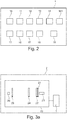
- Figure 2 shows a device 1 for scatter correction in an X-ray image, wherein the X-ray image has a superimposed structured pattern.
- the device comprises an X-ray receiving element 10, a pattern remover 11, a first subtraction module 12, a contrast measurement unit 13, a filter element 14, an estimation unit 15, a determination module 16, a linearization module 161, a second subtraction module 17, an output unit 18, and a processing unit 19.
- the X-ray receiving element 10 may be an interface which may receive image data from an X-ray acquisition device. This means, that the X-ray receiving element 10 may receive the image data from a data storage or directly from an X-ray acquisition device.
- the X-ray receiving element 10 may receive raw data generated by the X-ray acquisition device or pre-processed data, wherein the pre-processed data is the processed raw data.
- the X-ray receiving element 10 may receive image data comprising a superimposed structured pattern.
- the superimposed structure pattern 31 may be an effect of a structure pattern element in the X-ray image acquisition device or a scatter reducing element in the X-ray image acquisition device.
- the provided X-ray image 30, 40 does not need to comprise any object data. It may be a flat X-ray image 30 or an X-ray image 40 comprising object data.
- the pattern remover 11 processes of the X-ray image 30, 40 being received from the X-ray receiving element 10.
- the pattern remover 11 removes a superimposed structure pattern 31 from the X-ray image 30, 40 having a superimposed structured pattern 31.
- the pattern remover 11 provides a pattern corrected X-ray image 33, 43.
- the first subtraction module 12 subtracts the pattern corrected X-ray image 33, 43 from the X-ray image 40 and provides a structured pattern image 32, 42.
- the structured pattern image 32, 42 comprises the structured pattern 31 being removed from the X-ray image 30, 40. Further, the structured pattern image 32, 42 comprises scatter data which has not been removed by the pattern remover 11. Scatter data may result from objects to be imaged or from scatter reducing elements of the X-ray image acquisition device.
- the contrast measurement unit 13 applies a local structure contrast measurement function to the structured pattern image 32, 42.
- the local structure contrast measurement function may be an absolute value function, a minimum function, a maximum function, a standard deviation function, an average function, a median function, or a local FFT function for the amplitude etc.
- the local structure contrast measurement function may be an absolute value function.
- the local structure contrast measurement function that provides the absolute values from the structured pattern image 32, 42 resulting in a structure contrast image 34, 44.
- the filter element 14 is a low pass filter having a small kernel.
- the filter element 14 filters the structure contrast image 34, 44. This means, that high frequent changes of the contrast are filtered and only low frequent contrast changes remain in the image. This means, that the image data is smoothed. The result is a filtered structure contrast image 36, 46.
- the estimation unit 15 estimates a primary fraction 48 of the X-ray image 40 based on the filtered structure contrast image 36, 46.
- the estimation of the primary fraction may be performed with a first filtered structure contrast image 46 comprising an object and a second filtered structure contrast image 36 being a reference image comprising no object.
- the determination module 16 provides a filtered scatter signal 54 based on the primary fraction 48.
- the scatter fraction 50 may be derived from the difference between the total signal of the pattern corrected image and the primary fraction 48.
- the scatter fraction 50 is filtered with a low pass filter having a large kernel then the scatter signal 52 is derived from the scatter fraction 50 and the linearized pattern corrected X-ray image, wherein the linearized pattern corrected X-ray image may be provided by the linearization module 161.
- the scatter fraction 50 is multiplied with the linearized pattern corrected X-ray image resulting in a scatter signal 52. Then the scatter signal 52 is filtered with a low pass filter having a large kernel.
- the second subtraction module 17 subtracts at least a fraction of the filtered scatter signal 54 from the pattern corrected X-ray image 43.
- the result is a scatter corrected X-ray image 56.
- the scatter corrected X-ray image 56 has more contrast than the pattern corrected X-ray image 43 since the processing of the scatter data in the scatter fraction or the scatter signal enhances the contrast of the scatter in the scatter fraction and scatter signal without adding any noise of the filtered scatter signal. Therefore, the subtraction of the filtered scatter signal from the pattern corrected X-ray image 43 removes the scatter very efficiently.
- the output unit 18 may output the scatter corrected X-ray image 56.
- the output unit 18 may be a display or an interface which provides the data of the scatter corrected X-ray image 56.
- the processing unit 19 may control the X-ray receiving element 10, the pattern remover 11, the first subtraction module 12, the contrast measurement unit 13, the filter element 14, the estimation unit 15, the determination module 16, the second subtraction module 17, and the output unit 18.
- Figure 3a shows a system 2 for scatter correction in an X-ray image having a superimposed structured pattern.
- the system comprises an X-ray image acquisition device 20 and a device 1 according to the above description.
- the X-ray image acquisition device 20 comprises an X-ray radiation source 26 and an X-ray detector 23.
- the X-ray radiation being emitted by the X-ray radiation source 26 propagates through a G0 grating 25. Then the X-ray radiation propagates further through a G1 grating 24 and then through a G2 grating 22.
- the G2 grating 22 may comprise a structure pattern element 21.
- the structure pattern element 21 superimposes a structure pattern in the image being detected by the X-ray detector 23.
- the image data being detected by the X-ray detector 23 is provided to the device 1.
- the structure pattern element 21 is separate from the G2 grating 22.
- the structure pattern element 21 is located between the G2 grating 22 and the X-ray detector 23.
- the system may comprise oscillating grids.
- the parameters of a software grid model are tuned using measurements according to the present invention. A large number of raw data may be stored. In an offline evaluation, the so-called kernel-parameters of a scatter model will be tuned to match the results of the measured scatter in a better way. These improved parameters can be applied to images being acquired with a regular oscillating grid.
- Figure 4a shows the first exemplary embodiment of the structure pattern element 21.
- the structure pattern element 21 may be a plate having lamellas 210.
- the lamellas 210 has the same distance to each other. Further, the lamellas 210 have a width which is sufficient to provide a superimposed structured pattern on the acquired X-ray image.
- the height of the lamellas 210 may be modulated. This means for example that every fourth lamella 211 may be higher than the rest of the lamellas 210. The distance between the fourth lamellas hundred 11 may be around 150 ⁇ m. The height increase of the lamellas 211 in relation to the lamellas 210 may be around 50 ⁇ m.
- a duty cycle of the lamellas 210 may be modulated.
- the structure pattern element 21 comprises regions having the lamellas printed 10 and having lamellas 212 which are wider than the lamellas 210.
- the free space between the lamellas 212 is smaller than the space between the lamellas 210.
- the region of the lamellas 210 and the region of the lamellas 212 may alternate such that the region of lamellas 212 follows each region of 210 and vice versa.
- FIG. 5a shows a flat X-ray image 30 comprising a superimposed structured pattern 31 and flat scatter patterns 35.
- the flat X-ray image 30 does not comprise any object data and may be used as reference image.
- the flat X-ray image 30 may be parameterized using rotational symmetric functions C0. Parameters of this function C0 may be the source image receptor distance (SID), the maximum value, the radius, and the center position. Using measurements, functions as: Radius having the SID, maximum voltage value as reference, or the center position having the angulation as parameter with angulation describing the tilt value of the X-ray beam, for example 40°, may be obtained. All these functions are independent of the very system, so the number of calibration images for C0 may be limited to about one. The correction would use the function C0 instead of the actual C0-image. Using the function C0 a single flat X-ray image 30 may serve as reference for the processing of several X-ray images 40.
- the maximum grid contrast in a flat image may be measured.
- the same voltage and filtration as in the X-ray image may be used.
- the result is a reference structure contrast value.
- the reference structure contrast value depends on the voltage. The higher the voltage the lower is the contrast. This allows to calibrate the voltage dependency and use a look up table for the conversion.
- the grid contrast depends on the system Modulation Transfer Function MTF, which is constant with time.
- MTF Modulation Transfer Function
- the two-dimensional maximum grid contrast measurement may be replaced by a constant value. This embodiment is applicable because the remaining scatter will not be correct totally, i.e. with a factor of 100 %, but it will be implemented as a more moderate correction with a factor of less than 100 %.
- Figure 5b shows an X-ray image 40 comprising an object 41 and superimposed structured pattern 31. Further the X-ray image 40 comprises scatter patterns 401.
- the object 41 comprises several regions 410, 411 and 412 having different contrast. The regions 410, 411 and 412 also comprise portions of the scatter patterns 401.
- Figure 5c shows a pattern corrected flat X-ray image 33 being derived by the flat X-ray image 30 of figure 5a .
- the pattern corrected flat X-ray image 33 may be processed by a pattern remover which may be a software algorithm removing the superimposed structured pattern in the flat X-ray image 30.
- the pattern corrected flat X-ray image 33 still comprises flat scatter patterns 35.
- Figure 5d shows a pattern corrected X-ray image 43 being derived from the X-ray image 40 comprising an object of figure 5b .
- the pattern corrected X-ray image 43 may be processed by a pattern remover which may be a software algorithm removing the superimposed structured pattern in the X-ray image 40.
- the pattern corrected X-ray image 33 still comprises scatter patterns 401. Further, the pattern corrected X-ray image 33 comprises object 41 with its regions 410, 411 and 412. The regions 410, 411 and 412 comprise portions of the scatter pattern 401.
- Figure 6a shows a flat structure pattern image 32 comprising the superimposed structured pattern 31 that has been removed by the pattern remover 11 from the flat X-ray image 30.
- the flat structure pattern image 32 is acquired by the first subtraction module 12 by subtracting the flat pattern corrected X-ray image 33 from the flat X-ray image 30.
- the flat structure pattern image 32 is a reference image.
- Figure 6b shows a structured pattern image 42 comprising the superimposed structured pattern 31 and some scatter data 413, 414, and 415 from the object 41 of the X-ray image 40.
- the scatter data 413, 414, and 415 are scatter data from the regions 410, 411, and 412 of the X-ray image 40, respectively.
- the structure pattern image 42 is acquired by the first subtraction module 12 by subtracting the pattern corrected X-ray image 43 from the X-ray image 40.
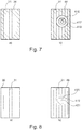
- Figure 7a shows a flat structure contrast image 34 being derived from the flat structure pattern image 32 by a local contrast measurement unit 13 with a local contrast measurement function.
- the mode of the structure pattern image 32 depends on the pattern removal algorithm of the pattern remover 11. Some removal algorithms provide a structure pattern image 32 which is zero in the average. Further removal algorithms provide a structure pattern image 32 which comprises the half maximum in the average.
- the local contrast measurement function is chosen depending on the removal algorithm. In the discussed example the removal algorithm provides a structure pattern image 32 which is zero in the average.
- the local contrast measurement function may thus be an absolute function which determines the absolute value of the structure pattern image 32.
- the structure contrast image 44 of figure 7b is therefore acquired in the same way as the flat structure contrast image 34.
- the source of the structure contrast image 44 is the structured pattern image 42 which is processed by the local contrast measurement unit 13 in the way described above.
- the structure contrast image 44 comprises the superimposed structured pattern 31 as well as the contrast data 416, 417, and 418 from the regions 410, 411, and 412 of the X-ray image 40.
- a low pass filter having a small kernel is applied to the flat structure contrast image 34 of figure 7a by a filter element 14.
- the low pass filtering filters high frequencies situations in the flat structure contrast image 34.
- the result is a filtered flat structure contrast image 36.
- the flat structure contrast image 34 comprises high frequent fluctuations in the corners of the image. Those fluctuations are filtered out in the flat structure contrast image 36 which becomes apparent in the blank corner regions of the flat structure contrast image 36.
- Figure 8b shows the filtered structure contrast image 46 being derived from filtering the structure contrast image 44 with low pass filter having a small kernel by the filter element 14.
- the removal of the high frequent fluctuations in the image data may enhance the structures of the contrast data 416, 417, and 418 of the structure contrast image 44 which can be seen in the filtered contrast data 419, 420, and 421 of the filtered contrast structure image 46.
- the corner regions of the filtered structure contrast image 46 are blank which indicates that the structure contrast image 44 has high frequent fluctuations in the corner regions.
- Figure 9 shows the primary fraction 48 of the X-ray image 40.
- the primary fraction 48 is acquired by the division of the filtered structure contrast image 46 by the filtered flat structure contrast image 36.
- the primary fraction regions 422, 423, and 424 are shown in the primary fraction 48.
- the peak-peak-contrast is only limited by the Modulation Transfer Function MTF of the system and is for example 25%. In a logarithmical image, this results in a constant peak-peak-difference independent of the exposure.
- the primary fraction 48 may be used to determine the scatter fraction 50 as shown in figure 10 .
- the scatter fraction 50 is so to say the negative of the primary fraction 48 since the addition of the primary fraction 48 with the scatter fraction 50 results in 1.
- the contrast of the primary fraction regions 422, 423, and 424 is inverted in the scatter fraction 50 which shows the scatter fraction regions 425, 426, and 427.
- Figure 11 shows the filtered scatter fraction 52 which results from filtering the scatter fraction 50 with a low pass filter having a large kernel.
- the scatter fraction regions 425, 426, and want to 27 are smeared out to the filtered scatter fraction regions 428, 429, and 430. Due to the filtering, the contrast between the filtered scatter fraction regions 428, 429, and 430 is higher than the contrast between the scatter fraction regions 425, 426, and 427, whereas the noise in the filtered scatter fraction 52 is the same as in the scatter fraction 50.
- Figure 12 shows the scatter signal 54 being derived from the filtered scatter fraction 52.
- the filtered scatter fraction 52 is multiplied to the linearized pattern corrected X-ray image 43.
- the scatter signal 54 shows the object 41 with the filtered scattered regions 431, 432, and 433. Further, the scatter signal 54 comprises filtered scatter patterns 402.
- the scatter corrected X-ray image 56 being shown in figure 13 is derived by subtracting the scatter signal 54 from the linearized pattern corrected X-ray image 43 and by applying the logarithm to the result. Due to the determination of the scatter signal 54 by filtering the scatter data, in this example the filtering of the scatter fraction 50, the scatter signal 54 comprises a high contrast. Therefore, by subtracting the high contrast scatter signal 54 from the linearized pattern corrected X-ray image 43, the contrast of the resulting image is also high. In a first embodiment, the total determined scatter signal 54 may be subtracted from the linearized pattern corrected X-ray image 43. This means, that all the scatter being determined by the scatter signal 54 is removed from the pattern corrected X-ray image 43.
- the scatter fraction 50 may be limited to a constant value if the scatter fraction 50 exceeds a threshold value. The constant value may be identical to the threshold value.
- a computer program or a computer program element is provided that is characterized by being adapted to execute the method steps of the method 100 according to one of the preceding embodiments, on an appropriate system.
- the computer program element 191 might therefore be stored on a computer unit, which might also be part of an embodiment of the present invention.
- This computing unit may be adapted to perform or induce a performing of the steps of the method described above. Moreover, it may be adapted to operate the components of the above described apparatus.
- the computing unit can be adapted to operate automatically and/or to execute the orders of a user.
- a computer program may be loaded into a working memory of a data processor 19.
- the data processor 19 may thus be equipped to carry out the method of the invention.
- This exemplary embodiment of the invention covers both, a computer program that right from the beginning uses the invention and a computer program that by means of an up-date turns an existing program into a program that uses the invention.
- the computer program element 191 might be able to provide all necessary steps to fulfil the procedure of an exemplary embodiment of the method as described above.
- a computer readable medium 190 such as a CD-ROM
- the computer readable medium has a computer program element stored on it which computer program element is described by the preceding section.
- a computer program may be stored and/or distributed on a suitable medium, such as an optical storage medium or a solid-state medium supplied together with or as part of other hardware, but may also be distributed in other forms, such as via the internet or other wired or wireless telecommunication systems.
- the computer program may also be presented over a network like the World Wide Web and can be downloaded into the working memory of a data processor from such a network.
- a medium for making a computer program element available for downloading is provided, which computer program element is arranged to perform a method according to one of the previously described embodiments of the invention.
Landscapes
- Health & Medical Sciences (AREA)
- Life Sciences & Earth Sciences (AREA)
- Engineering & Computer Science (AREA)
- Medical Informatics (AREA)
- Physics & Mathematics (AREA)
- Biomedical Technology (AREA)
- Molecular Biology (AREA)
- Biophysics (AREA)
- Nuclear Medicine, Radiotherapy & Molecular Imaging (AREA)
- Optics & Photonics (AREA)
- Pathology (AREA)
- Radiology & Medical Imaging (AREA)
- Veterinary Medicine (AREA)
- Heart & Thoracic Surgery (AREA)
- High Energy & Nuclear Physics (AREA)
- Surgery (AREA)
- Animal Behavior & Ethology (AREA)
- General Health & Medical Sciences (AREA)
- Public Health (AREA)
- Computer Vision & Pattern Recognition (AREA)
- General Physics & Mathematics (AREA)
- Theoretical Computer Science (AREA)
- Apparatus For Radiation Diagnosis (AREA)
- Image Processing (AREA)
- Analysing Materials By The Use Of Radiation (AREA)
Claims (12)
- Dispositif de correction de diffusion dans une image de rayons X, l'image de rayons X (30, 40) présentant un motif structuré superposé, le dispositif (1) comprenant :- un élément récepteur d'image de rayons X (10) ;- un éliminateur de motif (11) ; et- un premier module de soustraction (12) ;dans lequel l'élément récepteur d'image de rayons X (10) est configuré pour recevoir une image de rayons X (30, 40) comprenant un motif structuré superposé (31) ;
dans lequel l'éliminateur de motif (11) est configuré pour éliminer le motif structuré (31) de l'image de rayons X (30, 40) en sorte d'obtenir une image de rayons X au motif corrigé (43) ; et
dans lequel le premier module de soustraction (12) est configuré pour soustraire l'image de rayons X au motif corrigé (33, 43) de l'image de rayons X (40) en sorte d'obtenir une image de motif structuré (32, 42),
caractérisé en ce que le dispositif comprend en outre :- une unité de mesure de contraste (13) ;dans lequel l'unité de mesure de contraste (13) est configurée pour appliquer une fonction de mesure de contraste de structure locale à l'image de motif structuré (32, 42) en sorte d'obtenir une image de contraste de structure (34, 44). - Dispositif selon la revendication 1, dans lequel le dispositif comprend en outre :- un élément filtrant (14) ;dans lequel l'élément filtrant (14) est un filtre passe-bas pour l'image de contraste de structure (34, 44) fournissant une image de contraste de structure filtrée (36, 46).
- Dispositif selon la revendication 2, dans lequel le dispositif comprend en outre :- une unité d'estimation (15) ;dans lequel l'unité d'estimation (15) est configurée pour estimer une fraction primaire (48) de l'image de rayons X (40), dans lequel l'estimation est basée sur l'image de contraste de structure filtrée (36, 46).
- Dispositif selon la revendication 3, dans lequel le dispositif comprend en outre :- un module de détermination (16) ; et- un second module de soustraction (17) ;dans lequel le module de détermination (16) est configuré pour fournir un signal de diffusion filtré (54) sur la base d'une fraction de diffusion (50) déterminée à partir de la fraction primaire (48) ou d'une valeur (52) dérivée de la fraction de diffusion (50) ;
dans lequel le second module de soustraction (17) est configuré pour soustraire au moins une fraction du signal de diffusion filtré (54) de l'image de rayons X au motif corrigé (43) en sorte d'obtenir une image de rayons X à diffusion corrigée (56). - Dispositif selon la revendication 4, dans lequel, pour fournir le signal filtré (54), le module de détermination (16) est configuré pour appliquer un filtre passe-bas sur la fraction de diffusion (50) ou une valeur (52) dérivée de la fraction de diffusion (50).
- Système de correction de diffusion dans une image de rayons X présentant un motif structuré superposé, le système (2) comprenant :- un dispositif d'acquisition d'image de rayons X (20) ; et- un dispositif (1) selon l'une quelconque des revendications précédentes ;dans lequel le dispositif d'acquisition d'image de rayons X (20) comprend :- un élément de motif de structure (21) ;dans lequel le dispositif d'acquisition d'image de rayons X (20) fournit une image de rayons X comprenant une composante d'image de motif structurée.
- Procédé de correction de diffusion dans une image de rayons X présentant un motif structuré superposé, le procédé comprenant les étapes suivantes :a) la réception (101) d'une image de rayons X présentant un motif structuré superposé ; etb) l'élimination (102) des motifs structurés de l'image de rayons X avec un éliminateur de motif en sorte d'obtenir une image de rayons X au motif corrigé ;c) la soustraction (103) de l'image de rayons X au motif corrigé de l'image de rayons X avec un premier module de soustraction en sorte d'obtenir une image de motif structurée,caractérisé en ce que le procédé comprend l'étape supplémentaire suivante :
d) l'application (104) d'une fonction de mesure de contraste locale à l'image de motif structurée avec une unité de mesure de contraste pour obtenir une image de contraste de structure. - Procédé selon la revendication 7, dans lequel le procédé comprend l'étape supplémentaire suivante :
e) l'estimation (106) d'une fraction primaire de l'image de rayons X sur la base de l'image de motif de contraste de structure avec une unité d'estimation. - Procédé selon la revendication 8, dans lequel le procédé comprend les étapes supplémentaires suivantes :f) la détermination (109) d'un signal de diffusion filtré à partir de la fraction primaire ou d'une valeur tirée de la fraction primaire avec un module de détermination ;g) la soustraction (111) de la au moins une fraction du signal de diffusion filtré de l'image de rayons X au motif corrigé avec un second module de soustraction pour obtenir une image de rayons X à diffusion corrigée.
- Procédé selon la revendication 9, dans lequel l'étape f) comprend la sous-étape suivante :
fl) l'application (108) d'un filtre passe-bas sur la fraction de diffusion ou d'une valeur tirée de la fraction de diffusion pour fournir le signal de diffusion filtré. - Elément de programme d'ordinateur pour commander un appareil selon l'une quelconque des revendications 1 à 6, qui, lorsqu'il est exécuté par une unité de traitement (19), est à même d'effectuer les étapes de procédé de l'une quelconque des revendications 7 à 10.
- Support lisible par ordinateur (190) ayant stocké l'élément de programme (191) de la revendication 11.
Applications Claiming Priority (2)
| Application Number | Priority Date | Filing Date | Title |
|---|---|---|---|
| EP17181182.1A EP3427664A1 (fr) | 2017-07-13 | 2017-07-13 | Un dispositif de correction de la diffusion dans une image radiographique et un procédé de correction de la diffusion dans une image aux rayons x. |
| PCT/EP2018/068490 WO2019011832A1 (fr) | 2017-07-13 | 2018-07-09 | Dispositif de correction de diffusion dans une image radiographique et procédé de correction de diffusion dans une image radiographique |
Publications (3)
| Publication Number | Publication Date |
|---|---|
| EP3490455A1 EP3490455A1 (fr) | 2019-06-05 |
| EP3490455B1 true EP3490455B1 (fr) | 2020-02-19 |
| EP3490455B8 EP3490455B8 (fr) | 2020-04-01 |
Family
ID=59350711
Family Applications (2)
| Application Number | Title | Priority Date | Filing Date |
|---|---|---|---|
| EP17181182.1A Withdrawn EP3427664A1 (fr) | 2017-07-13 | 2017-07-13 | Un dispositif de correction de la diffusion dans une image radiographique et un procédé de correction de la diffusion dans une image aux rayons x. |
| EP18745512.6A Active EP3490455B8 (fr) | 2017-07-13 | 2018-07-09 | Un dispositif de correction de la diffusion dans une image radiographique et un procédé de correction de la diffusion dans une image aux rayons x. |
Family Applications Before (1)
| Application Number | Title | Priority Date | Filing Date |
|---|---|---|---|
| EP17181182.1A Withdrawn EP3427664A1 (fr) | 2017-07-13 | 2017-07-13 | Un dispositif de correction de la diffusion dans une image radiographique et un procédé de correction de la diffusion dans une image aux rayons x. |
Country Status (5)
| Country | Link |
|---|---|
| US (1) | US10918352B2 (fr) |
| EP (2) | EP3427664A1 (fr) |
| JP (1) | JP6865884B2 (fr) |
| CN (1) | CN109803585A (fr) |
| WO (1) | WO2019011832A1 (fr) |
Families Citing this family (3)
| Publication number | Priority date | Publication date | Assignee | Title |
|---|---|---|---|---|
| EP3805809A1 (fr) | 2019-10-10 | 2021-04-14 | Koninklijke Philips N.V. | Dispositif pour corriger la rétrodiffusion dans des images radiologiques |
| CN111588997B (zh) * | 2020-05-18 | 2022-07-12 | 上海联影医疗科技股份有限公司 | 散射量的确定方法、装置、设备和存储介质 |
| US12039745B2 (en) | 2021-07-27 | 2024-07-16 | GE Precision Healthcare LLC | Method and systems for removing anti-scatter grid artifacts in x-ray imaging |
Family Cites Families (34)
| Publication number | Priority date | Publication date | Assignee | Title |
|---|---|---|---|---|
| US7142705B2 (en) | 2001-05-01 | 2006-11-28 | Canon Kabushiki Kaisha | Radiation image processing apparatus, image processing system, radiation image processing method, storage medium, and program |
| JP2003150954A (ja) * | 2001-11-14 | 2003-05-23 | Fuji Photo Film Co Ltd | 周期的パターン抑制処理方法および装置 |
| EP1879020A1 (fr) | 2006-07-12 | 2008-01-16 | Paul Scherrer Institut | Interféromètre par rayons X pour l'imagerie à contraste de phase |
| CN100510725C (zh) | 2006-11-14 | 2009-07-08 | 北京国药恒瑞美联信息技术有限公司 | 用于消除散射辐射影响的虚拟滤线栅成像方法及其系统 |
| DE602007001270D1 (de) * | 2006-12-11 | 2009-07-23 | Agfa Healthcare Nv | Multiskalenbasiertes Verfahren zu Generierung eines kontrastverstärkten Bildes |
| JP5212376B2 (ja) * | 2007-10-02 | 2013-06-19 | 株式会社島津製作所 | 放射線画像処理装置および放射線画像処理プログラム |
| DE102008048683A1 (de) | 2008-09-24 | 2010-04-08 | Siemens Aktiengesellschaft | Verfahren zur Bestimmung von Phase und/oder Amplitude zwischen interferierenden benachbarten Röntgenstrahlen in einem Detektorpixel bei einem Talbot-Interferometer |
| JP5341471B2 (ja) | 2008-10-29 | 2013-11-13 | キヤノン株式会社 | 放射線画像処理装置、画像処理方法、x線透視装置及びその制御方法 |
| JP5459659B2 (ja) | 2009-10-09 | 2014-04-02 | キヤノン株式会社 | X線位相コントラスト像の撮像に用いられる位相格子、該位相格子を用いた撮像装置、x線コンピューター断層撮影システム |
| US8446411B2 (en) * | 2010-06-11 | 2013-05-21 | Microsoft Corporation | Adaptive image rendering and use of imposter |
| JP5961614B2 (ja) | 2010-09-03 | 2016-08-02 | コーニンクレッカ フィリップス エヌ ヴェKoninklijke Philips N.V. | 位相差イメージングのための格子装置、位相差イメージングのための装置、当該装置を有するx線システム、当該装置の使用方法 |
| WO2012056992A1 (fr) | 2010-10-25 | 2012-05-03 | 富士フイルム株式会社 | Détecteur de radiogrammes, dispositif radiographique, système radiographique |
| WO2012057045A1 (fr) | 2010-10-25 | 2012-05-03 | 富士フイルム株式会社 | Dispositif et système d'imagerie par rayons x |
| JP2012112882A (ja) | 2010-11-26 | 2012-06-14 | Fujifilm Corp | 放射線画像撮影用グリッド及びその製造方法、並びに放射線画像撮影システム |
| JP5150713B2 (ja) * | 2010-12-08 | 2013-02-27 | 富士フイルム株式会社 | 放射線画像検出装置、放射線撮影装置、放射線撮影システム |
| JP2012130586A (ja) * | 2010-12-22 | 2012-07-12 | Fujifilm Corp | 放射線画像検出装置、放射線撮影装置、及び放射線撮影システム |
| US8559753B2 (en) * | 2011-09-23 | 2013-10-15 | The Boeing Company | Reflection removal system |
| GB201119257D0 (en) | 2011-11-08 | 2011-12-21 | Eshtech Ltd | X-ray detection apparatus |
| DE102011088265B4 (de) * | 2011-12-12 | 2017-10-19 | Siemens Healthcare Gmbh | Verfahren zur Korrektur von aufgrund eines Streustrahlenrasters auftretenden Bildartefakten |
| EP2648157A1 (fr) * | 2012-04-04 | 2013-10-09 | Telefonaktiebolaget LM Ericsson (PUBL) | Procédé et dispositif pour transformer une image |
| US9280206B2 (en) * | 2012-08-20 | 2016-03-08 | Samsung Electronics Co., Ltd. | System and method for perceiving images with multimodal feedback |
| JP6006193B2 (ja) | 2013-03-28 | 2016-10-12 | 富士フイルム株式会社 | 放射線画像処理装置および方法並びにプログラム |
| JP6223781B2 (ja) | 2013-11-06 | 2017-11-01 | 富士フイルム株式会社 | 放射線画像処理装置および方法並びにプログラム |
| GB2521409A (en) * | 2013-12-18 | 2015-06-24 | Elekta Ab | Target-specific dose & scatter estimation in CT images |
| JP6362914B2 (ja) * | 2014-04-30 | 2018-07-25 | キヤノンメディカルシステムズ株式会社 | X線診断装置及び画像処理装置 |
| US9615808B2 (en) | 2014-05-27 | 2017-04-11 | Koninklijke Philips N.V. | Method and radiography system for grid-like contrast enhancement |
| GB201410635D0 (en) * | 2014-06-13 | 2014-07-30 | Univ Bangor | Improvements in and relating to the display of images |
| US10746671B2 (en) * | 2015-03-06 | 2020-08-18 | Ge Sensing & Inspection Technologies Gmbh | Imaging system and method with scatter correction |
| US9538975B2 (en) | 2015-04-08 | 2017-01-10 | Toshiba Medical Systems Corporation | Scatter correction method and apparatus for computed tomography imaging |
| CN107018421B (zh) * | 2016-01-27 | 2019-08-23 | 北京中科晶上科技有限公司 | 一种图像发送、接收方法及装置、系统 |
| DE102016206559B3 (de) * | 2016-04-19 | 2017-06-08 | Siemens Healthcare Gmbh | Verfahren zur Korrektur eines Röntgenbilds auf Effekte eines Streustrahlenrasters, Röntgeneinrichtung, Computerprogramm und elektronisch lesbarer Datenträger |
| US11039807B2 (en) * | 2016-12-19 | 2021-06-22 | Koninklijke Philips N.V. | System and method for dark-field-imaging |
| CN107168668A (zh) * | 2017-04-28 | 2017-09-15 | 北京七鑫易维信息技术有限公司 | 图像数据传输方法、装置以及存储介质、处理器 |
| EP3435325A1 (fr) | 2017-07-26 | 2019-01-30 | Koninklijke Philips N.V. | Correction de la diffusion pour l'imagerie en champ sombre |
-
2017
- 2017-07-13 EP EP17181182.1A patent/EP3427664A1/fr not_active Withdrawn
-
2018
- 2018-07-09 CN CN201880003887.6A patent/CN109803585A/zh active Pending
- 2018-07-09 JP JP2020500704A patent/JP6865884B2/ja not_active Expired - Fee Related
- 2018-07-09 WO PCT/EP2018/068490 patent/WO2019011832A1/fr not_active Ceased
- 2018-07-09 EP EP18745512.6A patent/EP3490455B8/fr active Active
- 2018-07-09 US US16/342,696 patent/US10918352B2/en active Active
Non-Patent Citations (1)
| Title |
|---|
| None * |
Also Published As
| Publication number | Publication date |
|---|---|
| EP3490455B8 (fr) | 2020-04-01 |
| EP3490455A1 (fr) | 2019-06-05 |
| JP6865884B2 (ja) | 2021-04-28 |
| CN109803585A (zh) | 2019-05-24 |
| WO2019011832A1 (fr) | 2019-01-17 |
| US10918352B2 (en) | 2021-02-16 |
| JP2020526311A (ja) | 2020-08-31 |
| US20200229785A1 (en) | 2020-07-23 |
| EP3427664A1 (fr) | 2019-01-16 |
Similar Documents
| Publication | Publication Date | Title |
|---|---|---|
| KR101389841B1 (ko) | 파노라마 영상 데이터 제공 방법 및 장치 | |
| EP3490455B1 (fr) | Un dispositif de correction de la diffusion dans une image radiographique et un procédé de correction de la diffusion dans une image aux rayons x. | |
| US7689055B2 (en) | Method and apparatus for enhancing image acquired by radiographic system | |
| WO2013125984A2 (fr) | Procédé d'annulation de bruit des radiographies numériques | |
| US9299141B2 (en) | Image analysis apparatus, radiation imaging apparatus, image analysis method, and storage medium | |
| US6151417A (en) | System for the processing of a sequence of noisy images and medical examination apparatus including such a system | |
| US10755389B2 (en) | Image processing apparatus, image processing method, and medium | |
| KR101095270B1 (ko) | 방사선 화상처리장치 및 방사선 화상처리 프로그램을 기록한 컴퓨터로 읽을 수 있는 매체 | |
| EP2901932B1 (fr) | Dispositif et procédé de détection de mouvements du corps | |
| CN103491875B (zh) | X射线诊断装置以及莫尔条纹去除方法 | |
| EP3622891A1 (fr) | Dispositif de calcul pour la détermination de défauts de ventilation | |
| CN107427269B (zh) | 放射线相位差摄影装置 | |
| JP3793039B2 (ja) | 画像処理方法、画像処理装置、放射線画像処理装置、画像処理システム及びプログラム | |
| EP3998948B1 (fr) | Appareil de traitement de données acquises par un système d'imagerie par rayons x à champ sombre et/ou à contraste de phase | |
| JP7508342B2 (ja) | 画像処理装置、画像処理方法、およびプログラム | |
| JP4765391B2 (ja) | 画像処理方法および画像処理装置ならびに画像処理プログラム | |
| JP5821790B2 (ja) | X線診断装置 | |
| JP7233211B2 (ja) | 画像処理装置、画像処理方法およびプログラム | |
| US20240027632A1 (en) | Image processing apparatus, image processing method, radiation imaging apparatus, and storage medium | |
| EP3922183A1 (fr) | Appareil de correction de la pénombre du collimateur dans une image à rayons x | |
| JPH0740293B2 (ja) | X線画像処理装置 | |
| WO2010018480A1 (fr) | Combinaison d'acquisitions radiographiques avec dimensions de foyer variées permettant d'améliorer la qualité de l'image | |
| US20220020129A1 (en) | Image matching apparatus, image matching method, and program |
Legal Events
| Date | Code | Title | Description |
|---|---|---|---|
| STAA | Information on the status of an ep patent application or granted ep patent |
Free format text: STATUS: UNKNOWN |
|
| STAA | Information on the status of an ep patent application or granted ep patent |
Free format text: STATUS: THE INTERNATIONAL PUBLICATION HAS BEEN MADE |
|
| PUAI | Public reference made under article 153(3) epc to a published international application that has entered the european phase |
Free format text: ORIGINAL CODE: 0009012 |
|
| STAA | Information on the status of an ep patent application or granted ep patent |
Free format text: STATUS: REQUEST FOR EXAMINATION WAS MADE |
|
| 17P | Request for examination filed |
Effective date: 20190228 |
|
| AK | Designated contracting states |
Kind code of ref document: A1 Designated state(s): AL AT BE BG CH CY CZ DE DK EE ES FI FR GB GR HR HU IE IS IT LI LT LU LV MC MK MT NL NO PL PT RO RS SE SI SK SM TR |
|
| AX | Request for extension of the european patent |
Extension state: BA ME |
|
| GRAP | Despatch of communication of intention to grant a patent |
Free format text: ORIGINAL CODE: EPIDOSNIGR1 |
|
| STAA | Information on the status of an ep patent application or granted ep patent |
Free format text: STATUS: GRANT OF PATENT IS INTENDED |
|
| DAV | Request for validation of the european patent (deleted) | ||
| DAX | Request for extension of the european patent (deleted) | ||
| INTG | Intention to grant announced |
Effective date: 20190917 |
|
| GRAS | Grant fee paid |
Free format text: ORIGINAL CODE: EPIDOSNIGR3 |
|
| GRAA | (expected) grant |
Free format text: ORIGINAL CODE: 0009210 |
|
| STAA | Information on the status of an ep patent application or granted ep patent |
Free format text: STATUS: THE PATENT HAS BEEN GRANTED |
|
| AK | Designated contracting states |
Kind code of ref document: B1 Designated state(s): AL AT BE BG CH CY CZ DE DK EE ES FI FR GB GR HR HU IE IS IT LI LT LU LV MC MK MT NL NO PL PT RO RS SE SI SK SM TR |
|
| REG | Reference to a national code |
Ref country code: CH Ref legal event code: EP |
|
| REG | Reference to a national code |
Ref country code: DE Ref legal event code: R096 Ref document number: 602018002561 Country of ref document: DE |
|
| REG | Reference to a national code |
Ref country code: CH Ref legal event code: PK Free format text: BERICHTIGUNG B8 |
|
| REG | Reference to a national code |
Ref country code: AT Ref legal event code: REF Ref document number: 1234015 Country of ref document: AT Kind code of ref document: T Effective date: 20200315 |
|
| RAP2 | Party data changed (patent owner data changed or rights of a patent transferred) |
Owner name: KONINKLIJKE PHILIPS N.V. |
|
| REG | Reference to a national code |
Ref country code: IE Ref legal event code: FG4D |
|
| REG | Reference to a national code |
Ref country code: DE Ref legal event code: R084 Ref document number: 602018002561 Country of ref document: DE |
|
| REG | Reference to a national code |
Ref country code: NL Ref legal event code: MP Effective date: 20200219 |
|
| PG25 | Lapsed in a contracting state [announced via postgrant information from national office to epo] |
Ref country code: NO Free format text: LAPSE BECAUSE OF FAILURE TO SUBMIT A TRANSLATION OF THE DESCRIPTION OR TO PAY THE FEE WITHIN THE PRESCRIBED TIME-LIMIT Effective date: 20200519 Ref country code: RS Free format text: LAPSE BECAUSE OF FAILURE TO SUBMIT A TRANSLATION OF THE DESCRIPTION OR TO PAY THE FEE WITHIN THE PRESCRIBED TIME-LIMIT Effective date: 20200219 Ref country code: FI Free format text: LAPSE BECAUSE OF FAILURE TO SUBMIT A TRANSLATION OF THE DESCRIPTION OR TO PAY THE FEE WITHIN THE PRESCRIBED TIME-LIMIT Effective date: 20200219 |
|
| REG | Reference to a national code |
Ref country code: GB Ref legal event code: 746 Effective date: 20200721 |
|
| REG | Reference to a national code |
Ref country code: LT Ref legal event code: MG4D |
|
| PG25 | Lapsed in a contracting state [announced via postgrant information from national office to epo] |
Ref country code: HR Free format text: LAPSE BECAUSE OF FAILURE TO SUBMIT A TRANSLATION OF THE DESCRIPTION OR TO PAY THE FEE WITHIN THE PRESCRIBED TIME-LIMIT Effective date: 20200219 Ref country code: BG Free format text: LAPSE BECAUSE OF FAILURE TO SUBMIT A TRANSLATION OF THE DESCRIPTION OR TO PAY THE FEE WITHIN THE PRESCRIBED TIME-LIMIT Effective date: 20200519 Ref country code: SE Free format text: LAPSE BECAUSE OF FAILURE TO SUBMIT A TRANSLATION OF THE DESCRIPTION OR TO PAY THE FEE WITHIN THE PRESCRIBED TIME-LIMIT Effective date: 20200219 Ref country code: GR Free format text: LAPSE BECAUSE OF FAILURE TO SUBMIT A TRANSLATION OF THE DESCRIPTION OR TO PAY THE FEE WITHIN THE PRESCRIBED TIME-LIMIT Effective date: 20200520 Ref country code: IS Free format text: LAPSE BECAUSE OF FAILURE TO SUBMIT A TRANSLATION OF THE DESCRIPTION OR TO PAY THE FEE WITHIN THE PRESCRIBED TIME-LIMIT Effective date: 20200619 Ref country code: LV Free format text: LAPSE BECAUSE OF FAILURE TO SUBMIT A TRANSLATION OF THE DESCRIPTION OR TO PAY THE FEE WITHIN THE PRESCRIBED TIME-LIMIT Effective date: 20200219 |
|
| PG25 | Lapsed in a contracting state [announced via postgrant information from national office to epo] |
Ref country code: NL Free format text: LAPSE BECAUSE OF FAILURE TO SUBMIT A TRANSLATION OF THE DESCRIPTION OR TO PAY THE FEE WITHIN THE PRESCRIBED TIME-LIMIT Effective date: 20200219 |
|
| PG25 | Lapsed in a contracting state [announced via postgrant information from national office to epo] |
Ref country code: ES Free format text: LAPSE BECAUSE OF FAILURE TO SUBMIT A TRANSLATION OF THE DESCRIPTION OR TO PAY THE FEE WITHIN THE PRESCRIBED TIME-LIMIT Effective date: 20200219 Ref country code: EE Free format text: LAPSE BECAUSE OF FAILURE TO SUBMIT A TRANSLATION OF THE DESCRIPTION OR TO PAY THE FEE WITHIN THE PRESCRIBED TIME-LIMIT Effective date: 20200219 Ref country code: PT Free format text: LAPSE BECAUSE OF FAILURE TO SUBMIT A TRANSLATION OF THE DESCRIPTION OR TO PAY THE FEE WITHIN THE PRESCRIBED TIME-LIMIT Effective date: 20200712 Ref country code: DK Free format text: LAPSE BECAUSE OF FAILURE TO SUBMIT A TRANSLATION OF THE DESCRIPTION OR TO PAY THE FEE WITHIN THE PRESCRIBED TIME-LIMIT Effective date: 20200219 Ref country code: SM Free format text: LAPSE BECAUSE OF FAILURE TO SUBMIT A TRANSLATION OF THE DESCRIPTION OR TO PAY THE FEE WITHIN THE PRESCRIBED TIME-LIMIT Effective date: 20200219 Ref country code: SK Free format text: LAPSE BECAUSE OF FAILURE TO SUBMIT A TRANSLATION OF THE DESCRIPTION OR TO PAY THE FEE WITHIN THE PRESCRIBED TIME-LIMIT Effective date: 20200219 Ref country code: RO Free format text: LAPSE BECAUSE OF FAILURE TO SUBMIT A TRANSLATION OF THE DESCRIPTION OR TO PAY THE FEE WITHIN THE PRESCRIBED TIME-LIMIT Effective date: 20200219 Ref country code: CZ Free format text: LAPSE BECAUSE OF FAILURE TO SUBMIT A TRANSLATION OF THE DESCRIPTION OR TO PAY THE FEE WITHIN THE PRESCRIBED TIME-LIMIT Effective date: 20200219 Ref country code: LT Free format text: LAPSE BECAUSE OF FAILURE TO SUBMIT A TRANSLATION OF THE DESCRIPTION OR TO PAY THE FEE WITHIN THE PRESCRIBED TIME-LIMIT Effective date: 20200219 |
|
| REG | Reference to a national code |
Ref country code: AT Ref legal event code: MK05 Ref document number: 1234015 Country of ref document: AT Kind code of ref document: T Effective date: 20200219 |
|
| REG | Reference to a national code |
Ref country code: DE Ref legal event code: R097 Ref document number: 602018002561 Country of ref document: DE |
|
| PLBE | No opposition filed within time limit |
Free format text: ORIGINAL CODE: 0009261 |
|
| STAA | Information on the status of an ep patent application or granted ep patent |
Free format text: STATUS: NO OPPOSITION FILED WITHIN TIME LIMIT |
|
| 26N | No opposition filed |
Effective date: 20201120 |
|
| PG25 | Lapsed in a contracting state [announced via postgrant information from national office to epo] |
Ref country code: AT Free format text: LAPSE BECAUSE OF FAILURE TO SUBMIT A TRANSLATION OF THE DESCRIPTION OR TO PAY THE FEE WITHIN THE PRESCRIBED TIME-LIMIT Effective date: 20200219 Ref country code: IT Free format text: LAPSE BECAUSE OF FAILURE TO SUBMIT A TRANSLATION OF THE DESCRIPTION OR TO PAY THE FEE WITHIN THE PRESCRIBED TIME-LIMIT Effective date: 20200219 |
|
| PG25 | Lapsed in a contracting state [announced via postgrant information from national office to epo] |
Ref country code: PL Free format text: LAPSE BECAUSE OF FAILURE TO SUBMIT A TRANSLATION OF THE DESCRIPTION OR TO PAY THE FEE WITHIN THE PRESCRIBED TIME-LIMIT Effective date: 20200219 Ref country code: MC Free format text: LAPSE BECAUSE OF FAILURE TO SUBMIT A TRANSLATION OF THE DESCRIPTION OR TO PAY THE FEE WITHIN THE PRESCRIBED TIME-LIMIT Effective date: 20200219 |
|
| REG | Reference to a national code |
Ref country code: BE Ref legal event code: MM Effective date: 20200731 |
|
| PG25 | Lapsed in a contracting state [announced via postgrant information from national office to epo] |
Ref country code: FR Free format text: LAPSE BECAUSE OF NON-PAYMENT OF DUE FEES Effective date: 20200731 Ref country code: LU Free format text: LAPSE BECAUSE OF NON-PAYMENT OF DUE FEES Effective date: 20200709 |
|
| PG25 | Lapsed in a contracting state [announced via postgrant information from national office to epo] |
Ref country code: BE Free format text: LAPSE BECAUSE OF NON-PAYMENT OF DUE FEES Effective date: 20200731 |
|
| PG25 | Lapsed in a contracting state [announced via postgrant information from national office to epo] |
Ref country code: IE Free format text: LAPSE BECAUSE OF NON-PAYMENT OF DUE FEES Effective date: 20200709 |
|
| REG | Reference to a national code |
Ref country code: CH Ref legal event code: PL |
|
| PG25 | Lapsed in a contracting state [announced via postgrant information from national office to epo] |
Ref country code: LI Free format text: LAPSE BECAUSE OF NON-PAYMENT OF DUE FEES Effective date: 20210731 Ref country code: CH Free format text: LAPSE BECAUSE OF NON-PAYMENT OF DUE FEES Effective date: 20210731 |
|
| PG25 | Lapsed in a contracting state [announced via postgrant information from national office to epo] |
Ref country code: TR Free format text: LAPSE BECAUSE OF FAILURE TO SUBMIT A TRANSLATION OF THE DESCRIPTION OR TO PAY THE FEE WITHIN THE PRESCRIBED TIME-LIMIT Effective date: 20200219 Ref country code: MT Free format text: LAPSE BECAUSE OF FAILURE TO SUBMIT A TRANSLATION OF THE DESCRIPTION OR TO PAY THE FEE WITHIN THE PRESCRIBED TIME-LIMIT Effective date: 20200219 Ref country code: CY Free format text: LAPSE BECAUSE OF FAILURE TO SUBMIT A TRANSLATION OF THE DESCRIPTION OR TO PAY THE FEE WITHIN THE PRESCRIBED TIME-LIMIT Effective date: 20200219 |
|
| PG25 | Lapsed in a contracting state [announced via postgrant information from national office to epo] |
Ref country code: MK Free format text: LAPSE BECAUSE OF FAILURE TO SUBMIT A TRANSLATION OF THE DESCRIPTION OR TO PAY THE FEE WITHIN THE PRESCRIBED TIME-LIMIT Effective date: 20200219 Ref country code: AL Free format text: LAPSE BECAUSE OF FAILURE TO SUBMIT A TRANSLATION OF THE DESCRIPTION OR TO PAY THE FEE WITHIN THE PRESCRIBED TIME-LIMIT Effective date: 20200219 |
|
| PGFP | Annual fee paid to national office [announced via postgrant information from national office to epo] |
Ref country code: GB Payment date: 20220719 Year of fee payment: 5 Ref country code: DE Payment date: 20220727 Year of fee payment: 5 |
|
| PG25 | Lapsed in a contracting state [announced via postgrant information from national office to epo] |
Ref country code: SI Free format text: LAPSE BECAUSE OF FAILURE TO SUBMIT A TRANSLATION OF THE DESCRIPTION OR TO PAY THE FEE WITHIN THE PRESCRIBED TIME-LIMIT Effective date: 20200219 |
|
| REG | Reference to a national code |
Ref country code: DE Ref legal event code: R119 Ref document number: 602018002561 Country of ref document: DE |
|
| GBPC | Gb: european patent ceased through non-payment of renewal fee |
Effective date: 20230709 |
|
| PG25 | Lapsed in a contracting state [announced via postgrant information from national office to epo] |
Ref country code: DE Free format text: LAPSE BECAUSE OF NON-PAYMENT OF DUE FEES Effective date: 20240201 Ref country code: GB Free format text: LAPSE BECAUSE OF NON-PAYMENT OF DUE FEES Effective date: 20230709 |