EP3490458B1 - Halter für dentalen röntgensensor - Google Patents
Halter für dentalen röntgensensor Download PDFInfo
- Publication number
- EP3490458B1 EP3490458B1 EP17749559.5A EP17749559A EP3490458B1 EP 3490458 B1 EP3490458 B1 EP 3490458B1 EP 17749559 A EP17749559 A EP 17749559A EP 3490458 B1 EP3490458 B1 EP 3490458B1
- Authority
- EP
- European Patent Office
- Prior art keywords
- ray imaging
- dental
- imaging media
- holder
- backing plate
- Prior art date
- Legal status (The legal status is an assumption and is not a legal conclusion. Google has not performed a legal analysis and makes no representation as to the accuracy of the status listed.)
- Active
Links
Images






Classifications
-
- A—HUMAN NECESSITIES
- A61—MEDICAL OR VETERINARY SCIENCE; HYGIENE
- A61B—DIAGNOSIS; SURGERY; IDENTIFICATION
- A61B6/00—Apparatus or devices for radiation diagnosis; Apparatus or devices for radiation diagnosis combined with radiation therapy equipment
- A61B6/50—Apparatus or devices for radiation diagnosis; Apparatus or devices for radiation diagnosis combined with radiation therapy equipment specially adapted for specific body parts; specially adapted for specific clinical applications
- A61B6/51—Apparatus or devices for radiation diagnosis; Apparatus or devices for radiation diagnosis combined with radiation therapy equipment specially adapted for specific body parts; specially adapted for specific clinical applications for dentistry
- A61B6/512—Intraoral means
-
- G—PHYSICS
- G03—PHOTOGRAPHY; CINEMATOGRAPHY; ANALOGOUS TECHNIQUES USING WAVES OTHER THAN OPTICAL WAVES; ELECTROGRAPHY; HOLOGRAPHY
- G03B—APPARATUS OR ARRANGEMENTS FOR TAKING PHOTOGRAPHS OR FOR PROJECTING OR VIEWING THEM; APPARATUS OR ARRANGEMENTS EMPLOYING ANALOGOUS TECHNIQUES USING WAVES OTHER THAN OPTICAL WAVES; ACCESSORIES THEREFOR
- G03B42/00—Obtaining records using waves other than optical waves; Visualisation of such records by using optical means
- G03B42/02—Obtaining records using waves other than optical waves; Visualisation of such records by using optical means using X-rays
- G03B42/04—Holders for X-ray films
- G03B42/042—Holders for X-ray films for dental applications
Definitions
- the invention relates generally to dental x-ray media/sensor holders (such as Film, Phosphor Plate or Digital Sensor) and more specifically it relates to a dental x-ray sensor/media holder for securing an x-ray sensor to a holder using suction created between the sensor and a backing plate of the sensor holder.
- dental x-ray media/sensor holders such as Film, Phosphor Plate or Digital Sensor
- a traditional dental x-ray acquisition involves exposing an x-ray film to x-ray energy after it has passed through site to be irradiated. The film is developed and an image is obtained. The dental x-ray film must be positioned relative to the target site in a predetermined and secure manner in order to obtain a useful image.
- Many numbers of x-ray film holders and positioning devices have long been known in the art, including for example, that shown in U.S. Pat. No. 3,473,026 .
- Both X-ray sensors and X-ray films are, as is long known in the art, secured in a predetermined position during the x-ray imaging procedure.
- holding and positioning devices have been developed for x-ray sensors.
- Digital sensors often have attached electrical connection cords such that the digital sensor transfers data to a storage or display device such as a computer.
- Phosphor imaging plates are also used in the dental industry.
- the imaging plate is irradiated and the x-ray shot is stored onto the imaging plate to be read later by a scanning machine or the like and the data is transferred to a storage or display device, such as a computer.
- dental x-ray imaging media x-ray sensosrs, sensors, imagers, image media or the like. Any such devices that are sensitive to such x-rays is within the scope of the invention.
- image media themselves are different in shape, size and configuration.
- traditional x-ray films are often manufactured inside an envelope before being used with a patient.
- Phosphor imaging plates are often very thin, not much thicker than a sheet of paper or two and are placed into a barrier envelope before being used in an x-ray procedure.
- Digital sensors tend to be fairly thick in respective comparison due to the internal energy sensing components required for such devices. It is envisioned that in the future, other type of dental imaging media will be developed using similar or perhaps completely different technologies. These all have at least some commonality in that they generally must fit within the oral cavity and they must be securely held in a desired location during the x-ray procedure.
- TW M515867 U discloses provision of a bonding member having two bonding surfaces provided on two opposite sides thereof. One of the bonding surfaces is adhered to the holding surface of the film-holding portion while the other bonding surface is used to adhesively hold the x-ray film or the digital image sensor thereto.
- the film holder being provided with a plurality of suction holes in order to hold an X-ray film in place is known from DE 10 2010 013591 A1 .
- Another way of securing dental imaging media in a desired location is by using adhesives or one or more straps as shown in U.S. Pat. No. 8,573,844 .
- This allows dental professionals to affix the media to a holder which in turn is connected to an aiming ring through a positioning arm, allowing for the aiming ring to be in alignment with the imaging media and the holder.
- Straps are not aesthetically pleasing and moreover provide extra bulkiness which is not needed while some adhesives are not suitable for use in the oral cavity.
- smaller holders can be produced when these securing means are eliminated. It is therefore desired to create a holder that is small, eliminates the use of adhesives or straps on imaging media and can be used for different sizes, shapes and configuration of imaging media.
- a dental practitioner Given the large number of different imaging media of different sizes, shapes and configurations, and given that many different x-ray procedures may be required in the oral cavity, a dental practitioner will normally keep a large number of imaging media holders in order to be reasonably certain that a proper holder is available at any given time for an x-ray procedure. It takes time and effort to match holders to specific imaging media and it is desired to eliminate this drawback.
- the present invention provides a holder that meets these desires by securing the x-ray imaging media to the holder using suction created in an evacuation chamber that exists between the sensor and the holder.
- the invention generally relates to a dental x-ray sensor holder which includes a bite block with a first end and a second end, a backing plate affixed to or formed contiguously with the second end of the bite block, and an opening to a cavity in the holder, wherein said cavity leads to an evacuation chamber for creating a vacuum between the holder and an X-ray sensor.
- An object is to provide a Dental X-ray Sensor Holder for securing an x-ray sensor to a holder using suction created between the sensor and a backing plate of the sensor holder.
- Another object is to provide a Dental X-ray Sensor Holder that eliminates the use of releasable or pressure sensitive adhesives and/or one or more straps to affix an X-ray sensor to a backing plate of a sensor holder.
- Another object is to provide a Dental X-ray Sensor Holder that has ridges that allow an even evacuation of air between the sensor in a sensor sheath and the backing plate of a sensor holder to create an even suction or vacuum effect to hold the sensor to the holder.
- Another object is to provide a Dental X-ray Sensor Holder that is provided with a swivel connection to a suction line to allow for unhindered movement of the suction line or holder when in the oral cavity of a patient.
- Another object is to provide a Dental X-ray Sensor Holder with a suction tubing and an adapter for connection to a saliva ejector of a suction system in a dental chair.
- Another object is to provide a Dental X-ray Sensor Holder with a suction tubing and an adapter for direct connection to a suction line in a dental chair or vacuum pump without the use of intermediate connections such as a saliva ejector or aspirator hose.
- Another object is to provide a Dental X-ray Sensor Holder that can hold any size of sensor by suction.
- Another object is to provide a Dental X-ray Sensor Holder with an aiming arm and a suction tubing such that that the suction tubing is embedded inside the aiming/positioning arm to make the holder more compact.
- the figures illustrate a sensor holder having a bite block with a first end and a second end, a backing plate affixed to or formed contiguously with the second end of the bite block, and an opening to a cavity in the holder, wherein said cavity leads to an evacuation chamber for creating a vacuum between the holder and an X-ray sensor.
- the cavity, opening and evacuation chamber may be of different configurations, shapes and sizes.
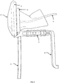
- FIGURE 1 and FIGURE 2 show a sensor securely attached to an X-ray holder.
- an X-ray sensor 1 is secured to the backing plate 3 of a sensor holder, the sensor being enclosed in a protective sheath 4.
- a suction tubing 6 is connected to the sensor holder. This allows for the creation of a vacuum between the backing plate of the sensor holder and the sensor/sheath combination when brought together with the suction effect holding the sensor to the backing plate.
- a positioning /aiming arm 8 is connected to the bite block of the sensor holder preferably through slots or apertures in the bite block and preferable in a friction fit manner.
- the backing plate is preferably affixed to or formed contiguously with the bite block.
- An adapter 7 allows for direct or indirect connection to suction lines present on most dental chairs (not shown) or other suction device to create a vacuum that pulls the sensor in tightly and holds it in place until the suction device is turned off.
- the cable 5 of the X-ray sensor allows for transmission of the sensor data to a receiver in a conventional manner.
- the bite block of the X-ray sensor holder will be positioned in a patient's oral cavity (not shown) and the patient will be instructed to bite upon the block. This locates the affixed or supported x-ray image media during the ensuing dental imaging acquisition procedure.
- Bite block 2 of the invention is of any suitable and conventional design, shape or configuration but can also have the unique inventive aspect of being designed to receive an aiming/suction arm 21 which has a suction tubing embedded in it to make the holder more compact, as shown in Figure 15 .
- vertical ridges 12 on the backing plate 3 of the sensor holder allow for an even removal of air from an evacuation chamber 14 (shown in Figure 7 ) between the sensor and the plate 3 to create a strong pulling force on the sensor. Air is evacuated from the space between the sensor and the backing plate 3 through the cavity 20.
- the sensor holder 10 has apertures or slits 9 within which a conventional aiming arm fits.
- an elastomeric material is injection overmolded onto the substrate 11 of the backing plate 3 to create a soft outer surface for contact with the sensor to enhance the suction effect.
- the substrate 11 of the backing plate 3 needs to be a fairly stiff material to assure that the X-ray sensor/media(Film, Phosphor Plate or Digital Sensor) is in parallel alignment with the aiming ring (not shown).
- Different designs can be realized for the ridges of the backing plate. In all cases, the ridges 12, 13 should be such that an even suction effect is created in the entirety of the evacuation chamber between the X-ray sensor and the backing plate.
- the ridges could be a part of the substrate 11 or could be a part of the elastomeric surface as in the case of injection overmolding.
- Figure 4 illustrates a different embodiment of the sensor holder 10a.
- the backing plate is shown as a substrate 11 with no elastomeric material attached or bonded to it.
- An appropriately shaped elastomeric material or foam can be bonded or attached to it, as shown in Figure 6 , to enhance the suction effect that secures the sensor in place.
- Ridges 12a are arranged to provide an evenly distributed suctioning effect.
- the soft surface in any embodiment could be, but is not limited to:
- the foam is a closed cell foam. Closed cell foams generally contain gas bubbles formed during the foam's expansion and cure. The bubbles are permanently locked in place and this enables it to resist liquids such as water and saliva and also act as an insulator and air barrier, enhancing the suction effect in the evacuation chamber.
- spherical protrusions 12b can be arranged on the substrate 11 to provide an even suction effect.
- Figure 7 is a cross sectional view of a preferred embodiment of the sensor holder 10 in operation with a suction tubing 6 to secure an X-ray sensor to the backing plate 3 of the holder 10. Air is drawn out of the evacuation chamber 14 in the sensor holder combination to create the vacuum required to hold the combination together.
- the suction tubing is connected to holder 10 through an extended opening 17, which leads through a cavity 20 to the evacuation chamber 14.
- the cavity 20 and/or evacuation chamber 14 may be of different configurations, shapes and sizes.
- the opening 17 can also be of different configurations, shapes and size .
- Figure 8 shows a bottom view of the sensor holder with a swivel opening 17a which extends in the direction of the longitudinal axis of the bite block 2.
- the swivel opening 17a can additionally be seen in Figure 9 .
- the opening allows swivel movements of the suction tubing 6 when connected to enable easy placement of the holder in the mouth of a patient.
- Swivel opening 17a allows suction tubing 6 to be positioned on either side of holder 10 to allow holder 10 to be used in different locations in the oral cavity. Opening 17, tubing 6 and evacuation chamber 14 are in fluid communication.
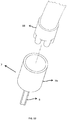
- the distal end 7 of the suction tubing 6 can be fitted with an adapter 7 for connection to a suction device such as a saliva ejector or aspirator hand piece(not shown) which in turn in connected to suction units such as the suction unit of a dental chair.
- a suction device such as a saliva ejector or aspirator hand piece(not shown)
- suction units such as the suction unit of a dental chair.
- Direct connections to suction units such as a vacuum pump can also be realized by using appropriate adapters.
- 7a shows an adapter to a suction line of a dental chair
- 7b shows an adapter to a saliva ejector.
- the adapter 7b is constructed to connect directly and firmly to a saliva ejector 18 to conduct a suction effect through the sensor holder tubing 6 to the evacuation chamber.
- the adapter 7b receives the saliva ejector preferably through a friction fit manner.
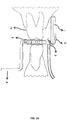
- the operation of the preferred embodiment of the holder involves holding the bite block 2 in place by teeth 19 and creating a vacuum between the sensor and the backing plate 3 to secure the sensor throughout the image acquisition process as shown in Figure 14 .
- An aiming/positioning arm 8 connected to an aiming ring (not shown) outside the oral cavity ensures that the sensor and the ring are in alignment.
- a suction tubing 6, connected on the proximal end to the opening in the holder and on the distal end to an adapter which in turn is connected to a suction device, provides a medium through which air is evacuated from the evacuation chamber 14 when the suction device (not shown) is engaged. Air is drawn out of the evacuation chamber to create a vacuum, which has the resultant effect of pulling the sensor securely to the backing plate.
- the ridges 12,13 on the backing plate ensure an even suction effect is created in the evacuation chamber.
- the suction tubing can be embedded inside the aiming/suction arm 21 for connection to the cavity 20 or evacuation chamber 14. This ensures a space saving holder and reduces the mass of material in the oral cavity of the patient during image acquisition.
Landscapes
- Health & Medical Sciences (AREA)
- Life Sciences & Earth Sciences (AREA)
- General Health & Medical Sciences (AREA)
- Oral & Maxillofacial Surgery (AREA)
- Physics & Mathematics (AREA)
- Medical Informatics (AREA)
- Engineering & Computer Science (AREA)
- General Physics & Mathematics (AREA)
- Optics & Photonics (AREA)
- Molecular Biology (AREA)
- Biophysics (AREA)
- Nuclear Medicine, Radiotherapy & Molecular Imaging (AREA)
- Dentistry (AREA)
- Pathology (AREA)
- Radiology & Medical Imaging (AREA)
- Biomedical Technology (AREA)
- Heart & Thoracic Surgery (AREA)
- High Energy & Nuclear Physics (AREA)
- Surgery (AREA)
- Animal Behavior & Ethology (AREA)
- Public Health (AREA)
- Veterinary Medicine (AREA)
- Apparatus For Radiation Diagnosis (AREA)
- Radiography Using Non-Light Waves (AREA)
- Dental Tools And Instruments Or Auxiliary Dental Instruments (AREA)
Claims (12)
- Dentalröntgenbildgebungsmedienhalter, umfassend:einen Aufbiss (2) mit einem ersten Ende, einem zweiten Ende und Öffnungen (9), wobei die Öffnungen (9) zur Aufnahme eines Zielbügels (8, 21) konfiguriert sind;eine Trägerplatte (3) mit einer ersten Seite und einer zweiten Seite, wobei die Trägerplatte (3) an dem zweiten Ende des Aufbisses (2) befestigt oder zusammenhängend mit dem zweiten Ende des Aufbisses (2) ausgebildet ist; dadurch gekennzeichnet, dass eine Öffnung (17) zu einem Hohlraum (20) in dem Halter vorgesehen ist;wobei der Hohlraum (20) zu einer Evakuierungskammer (14) an der zweiten Seite der Trägerplatte (3) führt, um ein Vakuum zwischen dem Halter und einem Röntgenbildgebungsmedium zu erzeugen, um das Röntgenbildgebungsmedium an dem Halter zu befestigen.
- Dentalröntgenbildgebungsmedienhalter nach Anspruch 1, wobei die Trägerplatte (3) Rippen (12, 12a, 13) oder
Vorsprünge (12b) aufweist, die eine gleichmäßige Evakuierung der Luft aus der Evakuierungskammer (14) ermöglichen, wobei die Evakuierungskammer (14) zwischen dem Röntgenbildgebungsmedium und der Trägerplatte (3) liegt. - Dentalröntgenbildgebungsmedienhalter nach Anspruch 2, wobei die Trägerplatte (3) ein Substrat (11) und ein weiches Material umfasst, und wobei das weiche Material an dem Substrat (11) befestigt oder gebunden ist, um eine Saugwirkung zwischen dem Röntgenbildgebungsmedium und der Trägerplatte (3) zu verstärken.
- Dentalröntgenbildgebungsmedienhalter nach Anspruch 3, wobei das weiche Material aus der Gruppe ausgewählt ist, die aus einem dauerhaft spritzgegossenen elastomeren Material, einem Schaumstoffband (15) und einer entfernbaren, geformten elastomeren Hülse besteht.
- Dentalröntgenbildgebungsmedienhalter nach Anspruch 4, wobei der Schaumstoff (15) ein geschlossenzelliger Schaumstoff ist.
- Dentalröntgenbildgebungsmedienhalter nach Anspruch 1, wobei der Halter mit einer Schwenkverbindung versehen ist.
- Dentalröntgenbildgebungsmedienhalter nach Anspruch 1, ferner umfassend: einen Saugschlauch (6), der so konfiguriert ist, dass er die Öffnung (17) mit einer Evakuierungsleitung verbindet.
- Dentalröntgenbildgebungsmedienhalter nach Anspruch 7, wobei die Evakuierungsleitung eine Saugleitung eines Dentalbehandlungsstuhls ist und wobei die Saugleitung durch einen ersten Adapter (7, 7 c) lösbar mit dem Saugschlauch (6) verbunden ist.
- Dentalröntgenbildgebungsmedienhalter nach Anspruch 7, wobei die Evakuierungsleitung ein Speichelauswerfer (18) ist und wobei der Speichelauswerfer (18) durch einen zweiten Adapter (7, 7d) lösbar mit dem Saugschlauch (6) verbunden ist.
- Dentalröntgenbildgebungsmedienhalter nach Anspruch 7, wobei der genannte Saugschlauch (6) im Inneren des Zielbügels (8, 21) eingebettet ist.
- Dentalröntgenbildgebungsmedienhalter nach Anspruch 1, wobei der Halter so konfiguriert ist, dass er Röntgenbildgebungsmedien verschiedener Formen und Größen sichert, die geeignet sind, die Positionierung in einem Mund eines Patienten für Aufnahmeverfahren zu ermöglichen.
- Verfahren zum Betreiben eines Dentalröntgenbildgebungsmedienhalters nach einem der Ansprüche 1 bis 11, umfassend:Bereitstellen eines Aufbisses (2) des Halters, der zwischen Ober- und Unterkieferzähnen eines Patienten gehalten wird,Einsetzen eines Zielbügels (8, 21) in die Öffnungen (9) des Aufbisses (2),Befestigen eines Röntgenbildgebungsmediums an einer Trägerplatte (3) des Halters und Erzeugen eines Vakuums zwischen der Trägerplatte (3) des Halters und dem Röntgenbildgebungsmedium, um das Röntgenbildgebungsmedium an der Trägerplatte (3) zu befestigen.
Applications Claiming Priority (2)
| Application Number | Priority Date | Filing Date | Title |
|---|---|---|---|
| US201662366661P | 2016-07-26 | 2016-07-26 | |
| PCT/US2017/043661 WO2018022582A1 (en) | 2016-07-26 | 2017-07-25 | Dental x-ray sensor holder |
Publications (2)
| Publication Number | Publication Date |
|---|---|
| EP3490458A1 EP3490458A1 (de) | 2019-06-05 |
| EP3490458B1 true EP3490458B1 (de) | 2020-08-19 |
Family
ID=59564233
Family Applications (1)
| Application Number | Title | Priority Date | Filing Date |
|---|---|---|---|
| EP17749559.5A Active EP3490458B1 (de) | 2016-07-26 | 2017-07-25 | Halter für dentalen röntgensensor |
Country Status (5)
| Country | Link |
|---|---|
| US (1) | US10376227B2 (de) |
| EP (1) | EP3490458B1 (de) |
| JP (1) | JP6954990B2 (de) |
| CA (1) | CA3031504C (de) |
| WO (1) | WO2018022582A1 (de) |
Families Citing this family (6)
| Publication number | Priority date | Publication date | Assignee | Title |
|---|---|---|---|---|
| US9179336B2 (en) | 2013-02-19 | 2015-11-03 | Mimosa Networks, Inc. | WiFi management interface for microwave radio and reset to factory defaults |
| US11191497B2 (en) * | 2018-10-16 | 2021-12-07 | Shayda Cullen | Digital dental x-ray sensor device having a rounded housing including a radio transceiver |
| US11337664B2 (en) * | 2018-11-15 | 2022-05-24 | Mitchell C Calderwood | Barrier-contained radiological sensor holder |
| US11759154B2 (en) | 2018-11-15 | 2023-09-19 | Mitchell C Calderwood | Barrier-contained radiological sensor holder |
| IL287938B2 (en) | 2019-05-10 | 2025-07-01 | Takeda Pharmaceuticals Co | Antibody-drug conjugates |
| GB2592594A (en) | 2020-03-02 | 2021-09-08 | Adaptix Ltd | An x-ray sensor |
Family Cites Families (10)
| Publication number | Priority date | Publication date | Assignee | Title |
|---|---|---|---|---|
| US3473026A (en) | 1966-09-21 | 1969-10-14 | William J Updegrave | Dental instruments for standardizing the bisecting-angle technique for periapical radiography |
| US7136452B2 (en) * | 1995-05-31 | 2006-11-14 | Goldpower Limited | Radiation imaging system, device and method for scan imaging |
| JPH10314164A (ja) * | 1997-05-17 | 1998-12-02 | Hanshin Gijutsu Kenkyusho:Kk | 上顎臼歯のx線撮影具および撮影方法 |
| US6652141B1 (en) | 2002-01-24 | 2003-11-25 | Cygnus Technologies, L.L.C. | Intraoral sensor |
| US7713058B2 (en) * | 2003-07-28 | 2010-05-11 | Atsushi Takahashi | Dental mirror, and an intraoral camera system using the same |
| US8573844B2 (en) * | 2006-05-30 | 2013-11-05 | Dentsply International Inc. | Adjustable dental X-ray image media holder |
| CA2763659C (en) * | 2009-05-27 | 2018-07-17 | Curtis L. Steward, Jr. | Universal dental x-ray sensor holder with elastomeric clamping vise |
| DE102010013591A1 (de) * | 2010-03-31 | 2011-10-06 | DüRR DENTAL AG | Röntgengerät und Verfahren zur Herstellung von Röntgenbildern für die zahnmedizinische oder kieferorthopädische Diagnostik |
| TR201909917T4 (tr) * | 2011-11-22 | 2019-07-22 | Duerr Dental Se | Bir depolama filminin okunması için düzenek ve yöntem. |
| TWM515867U (zh) * | 2015-08-12 | 2016-01-21 | Densmart Dental Co Ltd | 咬合持片裝置 |
-
2017
- 2017-07-25 EP EP17749559.5A patent/EP3490458B1/de active Active
- 2017-07-25 US US15/658,888 patent/US10376227B2/en active Active
- 2017-07-25 WO PCT/US2017/043661 patent/WO2018022582A1/en not_active Ceased
- 2017-07-25 CA CA3031504A patent/CA3031504C/en active Active
- 2017-07-25 JP JP2019504103A patent/JP6954990B2/ja active Active
Non-Patent Citations (1)
| Title |
|---|
| None * |
Also Published As
| Publication number | Publication date |
|---|---|
| US20180028132A1 (en) | 2018-02-01 |
| JP2019528099A (ja) | 2019-10-10 |
| JP6954990B2 (ja) | 2021-10-27 |
| CA3031504C (en) | 2023-07-11 |
| US10376227B2 (en) | 2019-08-13 |
| EP3490458A1 (de) | 2019-06-05 |
| WO2018022582A1 (en) | 2018-02-01 |
| CA3031504A1 (en) | 2018-02-01 |
Similar Documents
| Publication | Publication Date | Title |
|---|---|---|
| EP3490458B1 (de) | Halter für dentalen röntgensensor | |
| US5677537A (en) | Device for recording images in the oral cavity especially for dental diagnosis | |
| US6343875B1 (en) | Modular bite block and sensor holder apparatus for dental x-ray procedures | |
| US6811312B2 (en) | Dental x-ray positioning using adhesives | |
| US7959354B2 (en) | Adjustable dental x-ray image media holder | |
| US8573844B2 (en) | Adjustable dental X-ray image media holder | |
| US20100322386A1 (en) | Holder device for dental x-ray digital sensor | |
| US11399783B2 (en) | Dental X-ray sensor holder and dental X-ray sensor sheath therefor | |
| JP5665922B2 (ja) | 調整可能な歯科x線画像媒体ホルダ | |
| US10327719B2 (en) | Sensor holding apparatus for facilitating dental imaging | |
| US9247916B2 (en) | Sensor holding apparatus for facilitating dental imaging | |
| US20070025523A1 (en) | Digital dental x-ray sensor protector | |
| US20180279976A1 (en) | Intraoral sensor positioning system | |
| JP2006025972A (ja) | 用具ガードカバー |
Legal Events
| Date | Code | Title | Description |
|---|---|---|---|
| STAA | Information on the status of an ep patent application or granted ep patent |
Free format text: STATUS: UNKNOWN |
|
| STAA | Information on the status of an ep patent application or granted ep patent |
Free format text: STATUS: THE INTERNATIONAL PUBLICATION HAS BEEN MADE |
|
| PUAI | Public reference made under article 153(3) epc to a published international application that has entered the european phase |
Free format text: ORIGINAL CODE: 0009012 |
|
| STAA | Information on the status of an ep patent application or granted ep patent |
Free format text: STATUS: REQUEST FOR EXAMINATION WAS MADE |
|
| 17P | Request for examination filed |
Effective date: 20190116 |
|
| AK | Designated contracting states |
Kind code of ref document: A1 Designated state(s): AL AT BE BG CH CY CZ DE DK EE ES FI FR GB GR HR HU IE IS IT LI LT LU LV MC MK MT NL NO PL PT RO RS SE SI SK SM TR |
|
| AX | Request for extension of the european patent |
Extension state: BA ME |
|
| DAV | Request for validation of the european patent (deleted) | ||
| DAX | Request for extension of the european patent (deleted) | ||
| GRAP | Despatch of communication of intention to grant a patent |
Free format text: ORIGINAL CODE: EPIDOSNIGR1 |
|
| STAA | Information on the status of an ep patent application or granted ep patent |
Free format text: STATUS: GRANT OF PATENT IS INTENDED |
|
| INTG | Intention to grant announced |
Effective date: 20200313 |
|
| GRAS | Grant fee paid |
Free format text: ORIGINAL CODE: EPIDOSNIGR3 |
|
| GRAA | (expected) grant |
Free format text: ORIGINAL CODE: 0009210 |
|
| STAA | Information on the status of an ep patent application or granted ep patent |
Free format text: STATUS: THE PATENT HAS BEEN GRANTED |
|
| AK | Designated contracting states |
Kind code of ref document: B1 Designated state(s): AL AT BE BG CH CY CZ DE DK EE ES FI FR GB GR HR HU IE IS IT LI LT LU LV MC MK MT NL NO PL PT RO RS SE SI SK SM TR |
|
| REG | Reference to a national code |
Ref country code: CH Ref legal event code: EP Ref country code: CH Ref legal event code: NV Representative=s name: E. BLUM AND CO. AG PATENT- UND MARKENANWAELTE , CH |
|
| REG | Reference to a national code |
Ref country code: DE Ref legal event code: R096 Ref document number: 602017022026 Country of ref document: DE |
|
| REG | Reference to a national code |
Ref country code: AT Ref legal event code: REF Ref document number: 1303030 Country of ref document: AT Kind code of ref document: T Effective date: 20200915 |
|
| REG | Reference to a national code |
Ref country code: IE Ref legal event code: FG4D |
|
| REG | Reference to a national code |
Ref country code: SE Ref legal event code: TRGR |
|
| REG | Reference to a national code |
Ref country code: LT Ref legal event code: MG4D |
|
| REG | Reference to a national code |
Ref country code: NL Ref legal event code: MP Effective date: 20200819 |
|
| PG25 | Lapsed in a contracting state [announced via postgrant information from national office to epo] |
Ref country code: PT Free format text: LAPSE BECAUSE OF FAILURE TO SUBMIT A TRANSLATION OF THE DESCRIPTION OR TO PAY THE FEE WITHIN THE PRESCRIBED TIME-LIMIT Effective date: 20201221 Ref country code: FI Free format text: LAPSE BECAUSE OF FAILURE TO SUBMIT A TRANSLATION OF THE DESCRIPTION OR TO PAY THE FEE WITHIN THE PRESCRIBED TIME-LIMIT Effective date: 20200819 Ref country code: LT Free format text: LAPSE BECAUSE OF FAILURE TO SUBMIT A TRANSLATION OF THE DESCRIPTION OR TO PAY THE FEE WITHIN THE PRESCRIBED TIME-LIMIT Effective date: 20200819 Ref country code: GR Free format text: LAPSE BECAUSE OF FAILURE TO SUBMIT A TRANSLATION OF THE DESCRIPTION OR TO PAY THE FEE WITHIN THE PRESCRIBED TIME-LIMIT Effective date: 20201120 Ref country code: BG Free format text: LAPSE BECAUSE OF FAILURE TO SUBMIT A TRANSLATION OF THE DESCRIPTION OR TO PAY THE FEE WITHIN THE PRESCRIBED TIME-LIMIT Effective date: 20201119 Ref country code: NO Free format text: LAPSE BECAUSE OF FAILURE TO SUBMIT A TRANSLATION OF THE DESCRIPTION OR TO PAY THE FEE WITHIN THE PRESCRIBED TIME-LIMIT Effective date: 20201119 Ref country code: HR Free format text: LAPSE BECAUSE OF FAILURE TO SUBMIT A TRANSLATION OF THE DESCRIPTION OR TO PAY THE FEE WITHIN THE PRESCRIBED TIME-LIMIT Effective date: 20200819 |
|
| REG | Reference to a national code |
Ref country code: AT Ref legal event code: MK05 Ref document number: 1303030 Country of ref document: AT Kind code of ref document: T Effective date: 20200819 |
|
| PG25 | Lapsed in a contracting state [announced via postgrant information from national office to epo] |
Ref country code: PL Free format text: LAPSE BECAUSE OF FAILURE TO SUBMIT A TRANSLATION OF THE DESCRIPTION OR TO PAY THE FEE WITHIN THE PRESCRIBED TIME-LIMIT Effective date: 20200819 Ref country code: RS Free format text: LAPSE BECAUSE OF FAILURE TO SUBMIT A TRANSLATION OF THE DESCRIPTION OR TO PAY THE FEE WITHIN THE PRESCRIBED TIME-LIMIT Effective date: 20200819 Ref country code: LV Free format text: LAPSE BECAUSE OF FAILURE TO SUBMIT A TRANSLATION OF THE DESCRIPTION OR TO PAY THE FEE WITHIN THE PRESCRIBED TIME-LIMIT Effective date: 20200819 Ref country code: NL Free format text: LAPSE BECAUSE OF FAILURE TO SUBMIT A TRANSLATION OF THE DESCRIPTION OR TO PAY THE FEE WITHIN THE PRESCRIBED TIME-LIMIT Effective date: 20200819 Ref country code: IS Free format text: LAPSE BECAUSE OF FAILURE TO SUBMIT A TRANSLATION OF THE DESCRIPTION OR TO PAY THE FEE WITHIN THE PRESCRIBED TIME-LIMIT Effective date: 20201219 |
|
| PG25 | Lapsed in a contracting state [announced via postgrant information from national office to epo] |
Ref country code: CZ Free format text: LAPSE BECAUSE OF FAILURE TO SUBMIT A TRANSLATION OF THE DESCRIPTION OR TO PAY THE FEE WITHIN THE PRESCRIBED TIME-LIMIT Effective date: 20200819 Ref country code: DK Free format text: LAPSE BECAUSE OF FAILURE TO SUBMIT A TRANSLATION OF THE DESCRIPTION OR TO PAY THE FEE WITHIN THE PRESCRIBED TIME-LIMIT Effective date: 20200819 Ref country code: RO Free format text: LAPSE BECAUSE OF FAILURE TO SUBMIT A TRANSLATION OF THE DESCRIPTION OR TO PAY THE FEE WITHIN THE PRESCRIBED TIME-LIMIT Effective date: 20200819 Ref country code: EE Free format text: LAPSE BECAUSE OF FAILURE TO SUBMIT A TRANSLATION OF THE DESCRIPTION OR TO PAY THE FEE WITHIN THE PRESCRIBED TIME-LIMIT Effective date: 20200819 Ref country code: SM Free format text: LAPSE BECAUSE OF FAILURE TO SUBMIT A TRANSLATION OF THE DESCRIPTION OR TO PAY THE FEE WITHIN THE PRESCRIBED TIME-LIMIT Effective date: 20200819 |
|
| REG | Reference to a national code |
Ref country code: DE Ref legal event code: R097 Ref document number: 602017022026 Country of ref document: DE |
|
| PG25 | Lapsed in a contracting state [announced via postgrant information from national office to epo] |
Ref country code: AT Free format text: LAPSE BECAUSE OF FAILURE TO SUBMIT A TRANSLATION OF THE DESCRIPTION OR TO PAY THE FEE WITHIN THE PRESCRIBED TIME-LIMIT Effective date: 20200819 Ref country code: AL Free format text: LAPSE BECAUSE OF FAILURE TO SUBMIT A TRANSLATION OF THE DESCRIPTION OR TO PAY THE FEE WITHIN THE PRESCRIBED TIME-LIMIT Effective date: 20200819 Ref country code: ES Free format text: LAPSE BECAUSE OF FAILURE TO SUBMIT A TRANSLATION OF THE DESCRIPTION OR TO PAY THE FEE WITHIN THE PRESCRIBED TIME-LIMIT Effective date: 20200819 |
|
| PLBE | No opposition filed within time limit |
Free format text: ORIGINAL CODE: 0009261 |
|
| STAA | Information on the status of an ep patent application or granted ep patent |
Free format text: STATUS: NO OPPOSITION FILED WITHIN TIME LIMIT |
|
| PG25 | Lapsed in a contracting state [announced via postgrant information from national office to epo] |
Ref country code: SK Free format text: LAPSE BECAUSE OF FAILURE TO SUBMIT A TRANSLATION OF THE DESCRIPTION OR TO PAY THE FEE WITHIN THE PRESCRIBED TIME-LIMIT Effective date: 20200819 |
|
| 26N | No opposition filed |
Effective date: 20210520 |
|
| PG25 | Lapsed in a contracting state [announced via postgrant information from national office to epo] |
Ref country code: SI Free format text: LAPSE BECAUSE OF FAILURE TO SUBMIT A TRANSLATION OF THE DESCRIPTION OR TO PAY THE FEE WITHIN THE PRESCRIBED TIME-LIMIT Effective date: 20200819 |
|
| PG25 | Lapsed in a contracting state [announced via postgrant information from national office to epo] |
Ref country code: MC Free format text: LAPSE BECAUSE OF FAILURE TO SUBMIT A TRANSLATION OF THE DESCRIPTION OR TO PAY THE FEE WITHIN THE PRESCRIBED TIME-LIMIT Effective date: 20200819 |
|
| REG | Reference to a national code |
Ref country code: BE Ref legal event code: MM Effective date: 20210731 |
|
| PG25 | Lapsed in a contracting state [announced via postgrant information from national office to epo] |
Ref country code: LU Free format text: LAPSE BECAUSE OF NON-PAYMENT OF DUE FEES Effective date: 20210725 |
|
| PG25 | Lapsed in a contracting state [announced via postgrant information from national office to epo] |
Ref country code: IE Free format text: LAPSE BECAUSE OF NON-PAYMENT OF DUE FEES Effective date: 20210725 Ref country code: BE Free format text: LAPSE BECAUSE OF NON-PAYMENT OF DUE FEES Effective date: 20210731 |
|
| P01 | Opt-out of the competence of the unified patent court (upc) registered |
Effective date: 20230509 |
|
| PG25 | Lapsed in a contracting state [announced via postgrant information from national office to epo] |
Ref country code: CY Free format text: LAPSE BECAUSE OF FAILURE TO SUBMIT A TRANSLATION OF THE DESCRIPTION OR TO PAY THE FEE WITHIN THE PRESCRIBED TIME-LIMIT Effective date: 20200819 |
|
| PG25 | Lapsed in a contracting state [announced via postgrant information from national office to epo] |
Ref country code: HU Free format text: LAPSE BECAUSE OF FAILURE TO SUBMIT A TRANSLATION OF THE DESCRIPTION OR TO PAY THE FEE WITHIN THE PRESCRIBED TIME-LIMIT; INVALID AB INITIO Effective date: 20170725 |
|
| REG | Reference to a national code |
Ref country code: DE Ref legal event code: R079 Ref document number: 602017022026 Country of ref document: DE Free format text: PREVIOUS MAIN CLASS: A61B0006140000 Ipc: A61B0006510000 |
|
| PG25 | Lapsed in a contracting state [announced via postgrant information from national office to epo] |
Ref country code: MK Free format text: LAPSE BECAUSE OF FAILURE TO SUBMIT A TRANSLATION OF THE DESCRIPTION OR TO PAY THE FEE WITHIN THE PRESCRIBED TIME-LIMIT Effective date: 20200819 |
|
| PG25 | Lapsed in a contracting state [announced via postgrant information from national office to epo] |
Ref country code: TR Free format text: LAPSE BECAUSE OF FAILURE TO SUBMIT A TRANSLATION OF THE DESCRIPTION OR TO PAY THE FEE WITHIN THE PRESCRIBED TIME-LIMIT Effective date: 20200819 |
|
| PGFP | Annual fee paid to national office [announced via postgrant information from national office to epo] |
Ref country code: SE Payment date: 20240611 Year of fee payment: 8 |
|
| PG25 | Lapsed in a contracting state [announced via postgrant information from national office to epo] |
Ref country code: MT Free format text: LAPSE BECAUSE OF FAILURE TO SUBMIT A TRANSLATION OF THE DESCRIPTION OR TO PAY THE FEE WITHIN THE PRESCRIBED TIME-LIMIT Effective date: 20200819 |
|
| REG | Reference to a national code |
Ref country code: DE Ref legal event code: R082 Ref country code: DE Ref legal event code: R082 Ref document number: 602017022026 Country of ref document: DE Representative=s name: VENNER SHIPLEY GERMANY LLP, DE |
|
| REG | Reference to a national code |
Ref country code: DE Ref legal event code: R082 Ref document number: 602017022026 Country of ref document: DE Representative=s name: VENNER SHIPLEY GERMANY LLP, DE |
|
| PGFP | Annual fee paid to national office [announced via postgrant information from national office to epo] |
Ref country code: GB Payment date: 20250619 Year of fee payment: 9 |
|
| PGFP | Annual fee paid to national office [announced via postgrant information from national office to epo] |
Ref country code: FR Payment date: 20250620 Year of fee payment: 9 |
|
| PGFP | Annual fee paid to national office [announced via postgrant information from national office to epo] |
Ref country code: DE Payment date: 20250620 Year of fee payment: 9 |
|
| PGFP | Annual fee paid to national office [announced via postgrant information from national office to epo] |
Ref country code: IT Payment date: 20250619 Year of fee payment: 9 |
|
| PGFP | Annual fee paid to national office [announced via postgrant information from national office to epo] |
Ref country code: CH Payment date: 20250801 Year of fee payment: 9 |