EP3490498B1 - Bobine filetée - Google Patents
Bobine filetée Download PDFInfo
- Publication number
- EP3490498B1 EP3490498B1 EP17749088.5A EP17749088A EP3490498B1 EP 3490498 B1 EP3490498 B1 EP 3490498B1 EP 17749088 A EP17749088 A EP 17749088A EP 3490498 B1 EP3490498 B1 EP 3490498B1
- Authority
- EP
- European Patent Office
- Prior art keywords
- coil
- threaded
- arrangements
- inches
- minor
- Prior art date
- Legal status (The legal status is an assumption and is not a legal conclusion. Google has not performed a legal analysis and makes no representation as to the accuracy of the status listed.)
- Active
Links
Images


Classifications
-
- A—HUMAN NECESSITIES
- A61—MEDICAL OR VETERINARY SCIENCE; HYGIENE
- A61F—FILTERS IMPLANTABLE INTO BLOOD VESSELS; PROSTHESES; DEVICES PROVIDING PATENCY TO, OR PREVENTING COLLAPSING OF, TUBULAR STRUCTURES OF THE BODY, e.g. STENTS; ORTHOPAEDIC, NURSING OR CONTRACEPTIVE DEVICES; FOMENTATION; TREATMENT OR PROTECTION OF EYES OR EARS; BANDAGES, DRESSINGS OR ABSORBENT PADS; FIRST-AID KITS
- A61F2/00—Filters implantable into blood vessels; Prostheses, i.e. artificial substitutes or replacements for parts of the body; Appliances for connecting them with the body; Devices providing patency to, or preventing collapsing of, tubular structures of the body, e.g. stents
- A61F2/02—Prostheses implantable into the body
- A61F2/24—Heart valves ; Vascular valves, e.g. venous valves; Heart implants, e.g. passive devices for improving the function of the native valve or the heart muscle; Transmyocardial revascularisation [TMR] devices; Valves implantable in the body
- A61F2/2427—Devices for manipulating or deploying heart valves during implantation
- A61F2/2436—Deployment by retracting a sheath
-
- A—HUMAN NECESSITIES
- A61—MEDICAL OR VETERINARY SCIENCE; HYGIENE
- A61F—FILTERS IMPLANTABLE INTO BLOOD VESSELS; PROSTHESES; DEVICES PROVIDING PATENCY TO, OR PREVENTING COLLAPSING OF, TUBULAR STRUCTURES OF THE BODY, e.g. STENTS; ORTHOPAEDIC, NURSING OR CONTRACEPTIVE DEVICES; FOMENTATION; TREATMENT OR PROTECTION OF EYES OR EARS; BANDAGES, DRESSINGS OR ABSORBENT PADS; FIRST-AID KITS
- A61F2/00—Filters implantable into blood vessels; Prostheses, i.e. artificial substitutes or replacements for parts of the body; Appliances for connecting them with the body; Devices providing patency to, or preventing collapsing of, tubular structures of the body, e.g. stents
- A61F2/95—Instruments specially adapted for placement or removal of stents or stent-grafts
-
- A—HUMAN NECESSITIES
- A61—MEDICAL OR VETERINARY SCIENCE; HYGIENE
- A61F—FILTERS IMPLANTABLE INTO BLOOD VESSELS; PROSTHESES; DEVICES PROVIDING PATENCY TO, OR PREVENTING COLLAPSING OF, TUBULAR STRUCTURES OF THE BODY, e.g. STENTS; ORTHOPAEDIC, NURSING OR CONTRACEPTIVE DEVICES; FOMENTATION; TREATMENT OR PROTECTION OF EYES OR EARS; BANDAGES, DRESSINGS OR ABSORBENT PADS; FIRST-AID KITS
- A61F2/00—Filters implantable into blood vessels; Prostheses, i.e. artificial substitutes or replacements for parts of the body; Appliances for connecting them with the body; Devices providing patency to, or preventing collapsing of, tubular structures of the body, e.g. stents
- A61F2/01—Filters implantable into blood vessels
- A61F2/011—Instruments for their placement or removal
-
- A—HUMAN NECESSITIES
- A61—MEDICAL OR VETERINARY SCIENCE; HYGIENE
- A61F—FILTERS IMPLANTABLE INTO BLOOD VESSELS; PROSTHESES; DEVICES PROVIDING PATENCY TO, OR PREVENTING COLLAPSING OF, TUBULAR STRUCTURES OF THE BODY, e.g. STENTS; ORTHOPAEDIC, NURSING OR CONTRACEPTIVE DEVICES; FOMENTATION; TREATMENT OR PROTECTION OF EYES OR EARS; BANDAGES, DRESSINGS OR ABSORBENT PADS; FIRST-AID KITS
- A61F2/00—Filters implantable into blood vessels; Prostheses, i.e. artificial substitutes or replacements for parts of the body; Appliances for connecting them with the body; Devices providing patency to, or preventing collapsing of, tubular structures of the body, e.g. stents
- A61F2/02—Prostheses implantable into the body
- A61F2/24—Heart valves ; Vascular valves, e.g. venous valves; Heart implants, e.g. passive devices for improving the function of the native valve or the heart muscle; Transmyocardial revascularisation [TMR] devices; Valves implantable in the body
- A61F2/2427—Devices for manipulating or deploying heart valves during implantation
-
- A—HUMAN NECESSITIES
- A61—MEDICAL OR VETERINARY SCIENCE; HYGIENE
- A61F—FILTERS IMPLANTABLE INTO BLOOD VESSELS; PROSTHESES; DEVICES PROVIDING PATENCY TO, OR PREVENTING COLLAPSING OF, TUBULAR STRUCTURES OF THE BODY, e.g. STENTS; ORTHOPAEDIC, NURSING OR CONTRACEPTIVE DEVICES; FOMENTATION; TREATMENT OR PROTECTION OF EYES OR EARS; BANDAGES, DRESSINGS OR ABSORBENT PADS; FIRST-AID KITS
- A61F2/00—Filters implantable into blood vessels; Prostheses, i.e. artificial substitutes or replacements for parts of the body; Appliances for connecting them with the body; Devices providing patency to, or preventing collapsing of, tubular structures of the body, e.g. stents
- A61F2/02—Prostheses implantable into the body
- A61F2/24—Heart valves ; Vascular valves, e.g. venous valves; Heart implants, e.g. passive devices for improving the function of the native valve or the heart muscle; Transmyocardial revascularisation [TMR] devices; Valves implantable in the body
- A61F2/2442—Annuloplasty rings or inserts for correcting the valve shape; Implants for improving the function of a native heart valve
- A61F2/2466—Delivery devices therefor
-
- A—HUMAN NECESSITIES
- A61—MEDICAL OR VETERINARY SCIENCE; HYGIENE
- A61F—FILTERS IMPLANTABLE INTO BLOOD VESSELS; PROSTHESES; DEVICES PROVIDING PATENCY TO, OR PREVENTING COLLAPSING OF, TUBULAR STRUCTURES OF THE BODY, e.g. STENTS; ORTHOPAEDIC, NURSING OR CONTRACEPTIVE DEVICES; FOMENTATION; TREATMENT OR PROTECTION OF EYES OR EARS; BANDAGES, DRESSINGS OR ABSORBENT PADS; FIRST-AID KITS
- A61F2/00—Filters implantable into blood vessels; Prostheses, i.e. artificial substitutes or replacements for parts of the body; Appliances for connecting them with the body; Devices providing patency to, or preventing collapsing of, tubular structures of the body, e.g. stents
- A61F2/01—Filters implantable into blood vessels
- A61F2002/016—Filters implantable into blood vessels made from wire-like elements
-
- A—HUMAN NECESSITIES
- A61—MEDICAL OR VETERINARY SCIENCE; HYGIENE
- A61F—FILTERS IMPLANTABLE INTO BLOOD VESSELS; PROSTHESES; DEVICES PROVIDING PATENCY TO, OR PREVENTING COLLAPSING OF, TUBULAR STRUCTURES OF THE BODY, e.g. STENTS; ORTHOPAEDIC, NURSING OR CONTRACEPTIVE DEVICES; FOMENTATION; TREATMENT OR PROTECTION OF EYES OR EARS; BANDAGES, DRESSINGS OR ABSORBENT PADS; FIRST-AID KITS
- A61F2230/00—Geometry of prostheses classified in groups A61F2/00 - A61F2/26 or A61F2/82 or A61F9/00 or A61F11/00 or subgroups thereof
- A61F2230/0063—Three-dimensional shapes
- A61F2230/0091—Three-dimensional shapes helically-coiled or spirally-coiled, i.e. having a 2-D spiral cross-section
-
- F—MECHANICAL ENGINEERING; LIGHTING; HEATING; WEAPONS; BLASTING
- F16—ENGINEERING ELEMENTS AND UNITS; GENERAL MEASURES FOR PRODUCING AND MAINTAINING EFFECTIVE FUNCTIONING OF MACHINES OR INSTALLATIONS; THERMAL INSULATION IN GENERAL
- F16B—DEVICES FOR FASTENING OR SECURING CONSTRUCTIONAL ELEMENTS OR MACHINE PARTS TOGETHER, e.g. NAILS, BOLTS, CIRCLIPS, CLAMPS, CLIPS OR WEDGES; JOINTS OR JOINTING
- F16B37/00—Nuts or like thread-engaging members
Definitions
- Intravascular medical procedures allow the performance of therapeutic treatments in a variety of locations within a patient's body while requiring only relatively small access incisions.
- An intravascular procedure may, for example, eliminate the need for open-heart surgery, thereby reducing the risks, costs, and time associated with an open-heart procedure.
- the intravascular procedure also enables faster recovery times with lower associated costs and risks of complication.
- An example of an intravascular procedure which significantly reduces procedure and recovery time and cost over conventional open surgery is a heart valve replacement or repair procedure.
- An artificial valve is guided to the heart through the patient's vasculature.
- a catheter is inserted into the patient's vasculature and directed to the inferior vena cava.
- the catheter is then urged through the inferior vena cava toward the heart by applying force longitudinally to the catheter.
- the catheter Upon entering the heart from the inferior vena cava, the catheter enters the right atrium.
- the distal end of the catheter may be deflected by one or more wires positioned inside the catheter. Precise control of the distal end of the catheter allows for more reliable and faster positioning of a medical device and/or implant and other improvements in the procedure.
- An intravascularly delivered device needs to be placed precisely, as the device may be difficult to reposition after the device is fully deployed from the delivery system. Additionally, the ability to recapture and/or reposition a partially deployed device is desirable in the event that the distal end of the catheter moves relative to the target location and compromises the precise positioning of the device.
- An intravascular device delivery system can include an elongated body which is 75 centimeters or more in length within the patient's vasculature. Small movements, either longitudinally or rotationally, are limited by contact with the vasculature as the elongated body passes through the vasculature and around corners. Further, the internal friction of different layers and/or components of the intravascular device delivery system impairs the implementation of small movements by a medical profession or other user.
- the assembly comprises a delivery wire having a central core with a blade-shaped portion which extends inside a threading coil and has a blade thickness of preferably less than 40% of the blade width.
- the threading coil is fixed to the central core at least at the edges of the blade-shaped portion.
- a first helical coil has a first pitch and a first lumen.
- the first coil is threaded into a tubular hollow body that is lined with a spiral thread with a second pitch that is substantially the same as the first pitch.
- the hollow body may be a second coil.
- a first set of cutting elements extends form the first coil into the first lumen.
- a second set of cutting elements extends from the hollow body into the first lumen.
- the first and second sets of cutting elements are arranged with respect to each other such that a screw-like movement of the first helical coil relative to the hollow body causes a cutting element of the first set and a cutting element of the second set to pass each other closely enough to cut tissue.
- an intravascular catheter which includes a flexible guide wire mounted for relative rotational and reciprocal movements within a reciprocal and flexible first tube.
- a rotary and flexible second tube is mounted on the first tube to define an annular passage therebetween and has a rotary inner cutting head secured on a distal end thereof.
- the inner cutting head is closely fitted within an outer cutting head that is secured on the first tube.
- the cutting heads are adapted to cut a blockage in a blood vessel into fragments in response to rotation of the second tube and inner cutting head. The fragments are flushed-out from the inner cutting head and are conveyed away from the cutting heads and through the annular passage by facing spiral threads defined on the first and second tubes.
- the occluding device includes an expandable tubular body having a tubular wall defining a lumen formed therethrough.
- the tubular wall has a proximal end extending to a distal end along a longitudinal axis of the tubular body.
- a plurality of longitudinal slits is formed through the tubular wall to define a plurality of flexible strips bound by a proximal non-slit portion and a distal non-slit portion.
- a plurality of barbs is disposed on the flexible strips.
- the tubular body is configured to open radically to engage the barbs with the vessel wall defining an expanded state and to collapse along the longitudinal axis to draw the vessel wall radially inward defining a collapsed state.
- Occluding material is housed within the lumen of the tubular body and the occluding material is configured to move between a collapsed state and an expanded state with the tubular body.
- a threaded device for an intravascular device delivery system comprising at least one elastically deformable wire spiraled about a longitudinal axis.
- the at least one elastically deformable wire defines a guidewire receiving lumen through the device and has at least one thread on a radially outer surface, the at least one elastically deformable wire includes a major coil and a minor coil.
- the major coil has a major coil length
- the minor coil has a minor coil length
- a pitch of the thread is a sum of the major coil length and the minor coil length.
- an intravascular device delivery system comprising an elongated member having a proximal end, a distal end, and a longitudinal axis therebetween; a threaded device as described above; and a drive cable positioned in the elongated member and extending from the proximal end to the threaded device.
- the threaded device is positioned near the distal end of the elongated member and the drive cable is coaxial with the elongated member and rotationally fixed relative to the threaded device.
- the drive cable has a lumen therethrough to allow the guide wire to pass through a length of the drive cable.
- an intravascular device that includes inserting an elongated body containing a threaded coil and a distal end cap into a patient's vasculature.
- the intravascular device is positioned at the distal end of the elongated body.
- the method further includes applying a rotational force to the threaded coil, engaging a thread of the threaded coil with a complimentary thread; and rotating the threaded coil to apply a longitudinal force between the complimentary thread and the threaded coil.
- the present disclosure generally relates to intravascular device delivery systems or other steerable intravascular system.
- An intravascular device delivery system allows a medical professional to deliver an intravascular or other medical device to a target location in a patient's body. While the present disclosure will describe intravascular device delivery systems and applications thereof in relation to intravascular procedures in the heart, it should be understood that the devices and systems described herein may be applicable to other bodily lumens and/or cavities. Additionally, elements described in relation to any arrangement depicted and/or described herein may be combinable with elements described in relation to any other arrangement depicted and/or described herein. For example, any element described in relation to the arrangement depicted in FIG. 3-1 may be combinable with any element of the arrangement described in FIG. 10 , and any element described in relation to the arrangement described in FIG. 4-2 may be combinable with any element of the arrangement depicted in FIG. 8 .
- An intravascular device delivery system may include a flexible elongated member that has a distal end and a proximal end.
- a handle may be connected to a proximal end of the elongated member to allow a user, such as a medical professional and/or clinician, to control one or more movements of the elongated member.
- An intravascular device may be positioned at and/or connected to the distal end of the elongated member.
- the elongated member may include a plurality of elements.
- the elongated member may include a plurality of elements that extend from the proximal end to the distal end.
- at least one of the elements of the elongated member may be located radially about a drive cable.
- at least one element of the elongated member is located coaxially with and around a drive cable.
- the handle may include one or more controls (e.g., a knob, a button, a lever, or other controls) that may move at least one part of the intravascular device delivery system relative to another.
- the handle may include one or more controls for moving at least one element of the elongated member relative to another element of the elongated member.
- the handle may move an inner element relative to an outer element of the elongated member in a proximal direction, in a distal direction, in a rotational direction, or combinations thereof.
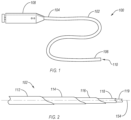
- FIG. 1 illustrates a schematic representation of an intravascular device delivery system 100.
- the system 100 includes an elongated member 102 having a proximal end 104 and a distal end 106.
- a handle 108 may be connected to the proximal end 104 of the elongated member 102.
- An intravascular device 110 may be positioned at and/or connected to the distal end 106.
- the elongated member 102 may be flexible, allowing the elongated member 102 to traverse a patient's tortuous vasculature or other anatomy.
- the elongated member 102 may deliver the intravascular device 110 (not visible) to a target location in the patient's body, such as delivering a heart valve repair device to the heart.
- the system 100 and elongated member 102 may be provided without an intravascular device 110 at the distal end 106 such that the system may recapture, reposition, or otherwise move an intravascular device previously positioned in the patient's body.
- the elongated member 102 of the system 100 may include one or more elements therein.
- An element of the elongated member 102 may include a catheter, a guidewire, a sheath, a drive cable, other tubular and/or solid elements, or combinations thereof.
- an element of the elongated member 102 may extend the entire length of the elongated member 102 from a proximal end 104 to a distal end 106 of the elongated member 102.
- an element of the elongated member 102 may have a length less than the entire length of the elongated member 102.
- an element may provide support to the elongated member 102 from the proximal end 104 toward the distal end 106 without continuing the entire length to the distal end 106.
- FIG. 2 is a side cutaway detail view of an elongated member 102 having a plurality of elements positioned radially within one another.
- an elongated member 102 may have outer sheath 112 with one or more elements positioned radially within the outer sheath 112.
- the outer sheath 112 may be an outermost element of the elongated member 102. In other arrangements, at least part of the outer sheath 112 may be within an outermost element of the elongated member 102.
- an elongated member 102 may have a delivery catheter 114 positioned radially within the outer sheath 112.
- the delivery catheter 114 may longitudinally overlap with a portion of the outer sheath 112 and the delivery catheter 114 may be within a lumen or other cavity of the outer sheath 112.
- the outer sheath 112 may have a plurality of elements positioned radially within the outer sheath 112.
- the delivery catheter 114 and an inner catheter 116 may be positioned radially within the outer sheath 112.
- both the delivery catheter 114 and inner catheter 116 may be radially within the outer sheath 112 and radially adjacent one another.
- the inner catheter 116 may be radially within the delivery catheter 114 and both may be radially within the outer sheath 112.
- the outer sheath 112 may have the delivery catheter 114, the inner catheter 116, and a drive cable 118 radially within the outer sheath 112, as shown in FIG. 2 .
- the outer sheath 112 and the delivery catheter 114 may be coaxial with one another.
- the outer sheath 112 and delivery catheter 114 may share a longitudinal axis 154 therethrough.
- the outer sheath 112, delivery catheter 114, inner catheter 116, drive cable 118, or combinations thereof may be coaxial and/or share the longitudinal axis 154 of the elongated member 102.
- outer sheath 112, delivery catheter 114, inner catheter 116, drive cable 118, or combinations thereof may not be coaxial and/or share the longitudinal axis 154 of the elongated member 102.
- the elongated member 102 may be an over-the-wire member and configured to have a guidewire 119 inserted through part of or all of the length of the elongated member 102.
- the drive cable 118 may have a lumen therethrough that may allow a guidewire 119 to pass through a length of the drive cable 118 and/or elongated member 102.
- a drive cable 118 may be a laterally flexible element with high torsional stiffness that is configured to transmit rotational force along a length thereof in a straight configuration and in a bent configuration.
- the drive cable 118 may be at least partially replaced by a cut hypotube.
- a cut hypotube may have flexibility in one or more lateral directions while transmitting torque therethrough with little to no rotation of a proximal end relative to a distal end.
- At least one of the outer sheath 112, delivery catheter 114, inner catheter 116, and drive cable 118 may be a steerable element.
- at least one of the outer sheath 112, delivery catheter 114, inner catheter 116, and drive cable 118 may have a plurality of wires, threads, sutures, or chambers that may allow a lateral force to be applied to the element, as known in the art, to allow steerability of the elongated member 102.
- the delivery catheter 114 may be a steerable catheter.
- a friction-reducing layer and/or coating may be located between the outer sheath 112 and the delivery catheter 114.
- a friction-reducing layer and/or coating may include a polytetrafluoroethylene (PTFE) layer positioned between the outer sheath 112 and the delivery catheter 114.
- PTFE polytetrafluoroethylene
- other lubricious coatings such as perfluoroalkoxy (PFA), fluorinated ethylene propylene, other fluoropolymers, other materials, or combinations thereof, may be applied between the elements of the elongated member 102 to reduce friction between the elements during longitudinal movement relative to one another.
- a friction-reducing layer and/or coating may be located between the drive cable 118 and the inner catheter 116, or other element radially surrounding the drive cable 118.
- the friction-reducing layer and/or coating may reduce rotation friction between the drive cable 118 and another element of the elongated member 102 when the drive cable 118 is rotated relative to the other element of the elongated member 102.
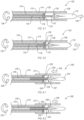
- FIG. 3-1 and FIG. 3-2 are side cross-sectional views of the distal end 106 of the elongated member 102 described in relation to FIG. 2 .
- the distal end 106 may have an intravascular device 110 positioned therein and/or connected thereto.
- the intravascular device 110 may be longitudinally adjacent a distal end cap 120.
- the distal end cap 120 may be longitudinally fixed to one or more elements of the elongated member 102.
- the distal end cap 120 may be longitudinally fixed relative to the drive cable 118.
- the distal end cap 120 may be longitudinally fixed relative to the delivery catheter 114 and/or inner catheter 116.
- the intravascular device 110 may be removably connected to the distal end cap 120.
- the distal end cap 120 may have one or more retention features (e.g., threaded, pins, grooves, resilient clips, etc.) thereon and the intravascular device 110 may have one or more complimentary retention features thereon, such that the intravascular device 110 may selectively engage with the distal end cap 120.
- the intravascular device 110 may abut the distal end cap 120 without interlocking, adhering, or otherwise connecting to the distal end cap 120.
- the distal end 106 may have an outer sheath 112 at least partially longitudinally overlapping the intravascular device 110.
- the intravascular device 110 may be an expandable device with a collapsed state and an expanded state.
- the intravascular device 110 may be a MITRACLIP mitral valve repair device having one or more deployable clips that expand radially from a body of the repair device.
- the outer sheath 112 may protect the repair device and the patient's vasculature from one another during delivery and positioning of the device before deployment.
- the intravascular device 110 may be a self-expanding intravascular device 110 with a contracted state and an expanded state.
- the intravascular device 110 may be biased toward the expanded state such that the outer sheath 112 holds the intravascular device 110 in the contracted state, and a removal of the outer sheath 112 (e.g., moving the outer sheath 112 in a proximal direction) from a longitudinally overlapping position, such as shown in FIG. 3-1 , may allow the expansion of the intravascular device 110 toward an expanded state.
- the intravascular device 110 may include a shape memory material ("SMM”) such as a shape memory polymer and/or a shape-memory metal.
- SMM shape memory material
- the intravascular device 110 may include or be made of a nickel titanium alloy.
- the intravascular device 110 in a contracted state may apply an expansive force to the outer sheath 112.
- the force experienced between the intravascular device 110 and the outer sheath 112 may create and/or increase a frictional force the outer sheath 112 and the intravascular device 110 and/or the delivery catheter 114.
- a longitudinal position of the intravascular device 110 may be at least partially controlled by a longitudinally moveable member within the distal end 106 of the elongated member 102. Friction within the elongated member 102 and/or between the elongated member 102 and the patient's vasculature may inhibit and/or limit fine movements of the intravascular device 110 (i.e., due partially to elastic and/or plastic deformation along the length of the elongated member 102). To control the precise location of the intravascular device 110, a longitudinal force may be applied to the intravascular device 110 that originates locally to the distal end 106 of the elongated member 102.
- a secondary positioning system in the elongated member 102 may provide fine adjustments to the position of the intravascular device 110.
- FIG. 3-1 illustrates an example of a secondary positioning system that may convert a rotation of the drive cable 118 to a longitudinal movement of the intravascular device 110.
- the drive cable 118 may be rotationally fixed relative to a threaded coil 122.
- the threaded coil 122 may be made of or include a coiled wire or other member that allows the threaded coil 122 to elastically deform during passage through the patient's vasculature.
- the threaded coil 122 may be biased to a substantially straight orientation.
- the threaded coil 122 may be shapeable to provide a shapeable distal end 106 to the elongated member 102.
- the threaded coil 122 may have a plurality of threads thereon, such that the threaded coil 122 may function as a screw gear, as will be described in more detail in relation to FIG. 5 through FIG. 12 .
- the intravascular device 110 may be at least partially or entirely radially within the outer sheath 112.
- a user may rotate the drive cable 118.
- the drive cable 118 may be rotationally fixed relative to the threaded coil 122.
- the drive cable 118 may be welded to the threaded coil 122.
- the drive cable 118 may be fixed relative to the threaded coil 122 by an adhesive or by a mechanical connection, such as interlocking features.
- the drive cable 118 may be fixed relative to the threaded coil 122 by one or more intermediate elements, such as a pin, a staple, a clip, or other mechanical link between the drive cable 118 and the threaded coil 122.
- the threaded coil 122 may engage with a complimentary thread 124 on the distal end cap 120 of the elongated member 102.
- the complimentary thread 124 may apply a longitudinal force to the threaded coil 122 upon rotation of the threaded coil 122.
- FIG. 3-1 illustrates a clockwise rotation 128 (from a proximal perspective) of the drive cable 118.
- the rotation of the drive cable 118 is transmitted to the threaded coil 122 and the threaded coil 122 may rotate relative to the distal end cap 120.
- the threaded coil 122 may engage with the complimentary threads 124 of the distal end cap 120, which may, in turn, urge the threaded coil 122 in a distal direction 130.
- the threaded coil 122 may engage with one or more complementary threads on the delivery catheter 114 and/or the inner catheter 116. The movement of the threaded coil 122 may urge the intravascular device 110 in a distal direction 130.
- the threaded coil 122 may be connected to the intravascular device 110. In other arrangements, the threaded coil 122 may be longitudinally fixed to the intravascular device 110 and rotationally independent from the intravascular device 110. For example, the threaded coil 122 may be connected to the intravascular device 110 with a rotational bearing 126, such that the threaded coil 122 and intravascular device 110 are rotationally independent.
- the bearing 126 may be a ball bearing. In other arrangements, the bearing 126 may be a slide bearing.
- the threaded coil 122 may be rotationally independent from the intravascular device 110, and the intravascular device 110 may be rotationally keyed to the outer sheath 112, distal end cap 120, or other element of the elongated member 102.
- the counter-clockwise rotation 132 (from a proximal perspective) of the drive cable 118 may be transmitted to the threaded coil 122.
- the threaded coil 122 may rotate relative to the distal end cap 120.
- the threaded coil 122 may engage with the complimentary threads 124 of the distal end cap 120, which may, in turn, urge the threaded coil 122 in a proximal direction 134.
- the threaded coil 122 may engage with one or more complementary threads on the delivery catheter 114 and/or the inner catheter 116. The movement of the threaded coil 122 may urge the intravascular device 110 in a proximal direction 134.
- FIG. 4-1 another example of an elongated member 202 is shown.
- Rotation of a drive cable 218 coupled to a threaded coil 222 in a clockwise direction 228 may cause the threaded coil 222 to engage with complimentary threads 224 and move the threaded coil 222 longitudinally.
- the threaded coil 222 may apply a longitudinal force to and move an outer sheath 212 or other element of the elongated member 202 in the proximal direction 234.
- the outer sheath 212 or other element of the elongated member 202 may move relative to the delivery catheter 214, inner catheter 216, distal end cap 220, or combinations thereof.
- the outer sheath 212 or other element of the elongated member 202 may move longitudinally relative to the intravascular device 210.
- the outer sheath 212 may be shortened to longitudinally overlap the intravascular device 210 and a portion of the delivery catheter 214. In other arrangements, the outer sheath 212 may extend from a proximal end of the elongated member 202 to the distal end of the elongated member 202, such as in the elongated member 102 described in relation to FIG. 1 and FIG. 2 .
- the threaded coil 222 may be longitudinally fixed relative to the outer sheath 212 by a distal connection member 227.
- the distal connection member 227 may be continuous between the threaded coil 222 and the outer sheath 212 (i.e., a continuous disc).
- the distal connection member 227 may be one or more struts or other radial connection members that connect the threaded coil 222 and the outer sheath 212.
- the distal connection member 227 that connects the threaded coil 222 to the outer sheath 212 may be connected to a bearing 226.
- the distal connection member 227 may be rotationally independent of the threaded coil 222 and located between the bearing 226 and the outer sheath 212.
- the distal connection member 227 may be rotationally fixed relative to the threaded coil 222 and a bearing 226 may be located between the distal connection member 227 and the outer sheath 212.
- the outer sheath 212 and distal connection member 227 may be both rotationally fixed relative to the threaded coil 222.
- the intravascular device 210 may expand radially outward beyond the outer sheath 212 upon proximal movement of the outer sheath 212 relative to the intravascular device 210.
- the longitudinal position of the intravascular device 210 relative to the distal end cap 220 may be fixed. For example, after a partial expansion of the intravascular device 210, the intravascular device 210 may be urged back to a contracted state.
- the counter-clockwise rotation 232 (opposite that in FIG. 4-1 ) of the drive cable 218 may be transmitted to the threaded coil 222.
- the rotation may cause the threaded coil 222 to engage with complimentary threads 224 and move the threaded coil 222 longitudinally.
- the threaded coil 222 may apply a longitudinal force to and move an outer sheath 212 or other element of the elongated member 202 in the distal direction 230.
- the outer sheath 212 or other element of the elongated member 202 may move relative to the delivery catheter 214, inner catheter 216, distal end cap 220, or combinations thereof. In at least one arrangement, the outer sheath 212 or other element of the elongated member 202 may move longitudinally relative to the intravascular device 210.
- the bearing 226 may be a one-way bearing, allowing rotation in a first direction and resisting rotation in a second direction.
- a one-way bearing may be used to allow only deployment of an intravascular device, if recapture or other proximal movement of the intravascular device is undesirable.
- the threaded coil may engage with a complimentary thread on the distal connection member, intravascular device, or other component of the intravascular device delivery system.
- the threaded coil may be longitudinally fixed by a bearing relative to the distal end cap, the threaded coil may engage with a complimentary thread on the intravascular device.
- the threaded coil may rotate while remaining in the same longitudinal position relative to the distal end cap, and the rotation of the threaded coil may urge the intravascular device proximally or distally.
- the threaded coil may rotate while remaining in the same longitudinal position relative to the distal end cap, and the rotation of the threaded coil may urge the outer sheath proximally or distally.
- a threaded coil may include a plurality of coils helixed together, such as is described in relation to FIG. 5 through FIG 9 .
- a threaded coil may include a single coil.
- the single coil may be a shaped coil to create threads, which engage with complimentary threads on the distal end cap.
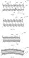
- FIG. 5 is a perspective cutaway view of one example of a threaded coil 222.
- the threaded coil 222 may include a major coil 236 and a minor coil 238 that may be helixed together (i.e., interlocked spiral coils) to create a substantially continuous spiral coil.
- the major coil 236 and minor coil 238 may have different radial widths, such that the major coil 236 projects radially outward farther than the minor coil 238, creating a spiral recess in the threaded coil 222 that may act as a thread to engage with a complimentary thread and transfer forces.
- the major coil 236 may have a major coil length 240 in the longitudinal direction.
- the minor coil 238 may have a minor coil length 242 in the longitudinal direction.
- the major coil length 240 and/or the minor coil length 242 may be constant along a length of the threaded coil 222.
- the major coil length 240 and/or the minor coil length 242 may vary along a length of the threaded coil 222. For example, lateral flexibility at a distal end of the threaded coil 222 may be increased or altered by decreasing the major coil length 240 and/or minor coil length 242 closer to the distal end of the threaded coil 222.
- the major coil length 240 and the minor coil length 242 may be substantially equal.
- the major coil length 240 and the minor coil length 242 may both be about 1 millimeter.
- the major coil length 240 may be greater than the minor coil length 242.
- the major coil length 240 may be about 1.0 millimeter and the minor coil length 242 may be less than 1.0 millimeter.
- the major coil length 240 may be less than the minor coil length 242.
- the major coil length 240 may be about 1.0 millimeter and the minor coil length 242 may be more than 1.0 millimeter.
- the threaded coil 222 may be tightly packed such that the major coil 236 and minor coil 238 abut one another along at least a length of the threaded coil 222.
- the distal end and/or proximal ends of threaded coil 222 are tightly packed such that major coil 236 and minor coil 238 abut one another.
- the minor coil 238 is tightly packed.
- Such an arrangement of the distal and/or proximal end of a coil may enhance the ability to attach the proximal end or the distal end of the coil to other elements of the delivery device by such methods as welding, brazing, adhesives or other fixation methods.
- the threaded coil 222 may be tightly packed such that the major coil 236 and minor coil 238 abut one another along the entire length of the threaded coil 222.
- the threaded coil 222 may be loosely packed, such that there is a space between the major coil 236 and the minor coil 238 in the longitudinal direction.
- the major coil length 240 and the minor coil length 242 may be substantially equal to the pitch 244.
- the pitch 244 may be greater than the sum of the major coil length 240 and the minor coil length 242.
- the major coil 236 and the minor coil 238 may define a lumen therethrough with a lumen diameter 250.
- the lumen diameter 250 may be sized to permit a guidewire or other elongated element to extend at least partially through the threaded coil 222.
- the lumen diameter 250 may be in a range having an upper value, a lower value, or an upper and lower value including any of 0.635mm (0.025 inches), 0.762mm (0.030 inches), 0.889mm (0.035 inches), 1.016mm (0.040 inches), 1.143mm (0.045 inches), 1.270mm (0.050 inches), 1.524mm (0.060 inches), 1.778mm (0.070 inches), 2.032mm (0.080 inches), 2.286mm (0.090 inches), 2.540mm (0.100 inches), or any values therebetween.
- the lumen diameter 250 may be greater than 0.635mm (0.025 inches).
- the lumen diameter 250 may be less than 2.540mm (0.100 inches).
- the lumen diameter 250 may be in a range of 0.635mm (0.025 inches) to 2.540mm (0.100 inches). In at least one example, the lumen diameter 250 may be about 0.889mm (0.035 inches).
- the minor coil 238 has a minor coil height 246 that is a radial distance from an inner surface (i.e., the surface that partially defines the lumen) of the minor coil 238 and an outer surface of the minor coil 238.
- the major coil 236 has a major coil height 248 that is a radial distance from an inner surface (i.e., the surface that partially defines the lumen) of the major coil 236 and an outer surface of the major coil 236.
- the difference between the minor coil height 246 and the major coil height 248 may partially define a thread depth of the threaded coil 222.
- a thread depth may be in a range having an upper value, a lower value, or an upper and lower value including any of 0.127mm (0.005 inches), 0.254mm (0.010 inches), 0.381 mm (0.015 inches), 0.508mm (0.020 inches), 0.635mm (0.025 inches), 0.762mm (0.030 inches), 0.889mm (0.035 inches), 1.016mm (0.040 inches).
- the thread depth is greater than 0.127mm (0.005 inches).
- the thread depth is less than 1.016mm (0.040 inches).
- the thread depth is between 0.127mm (0.005 inches) and 1.016mm (0.040 inches).
- FIG. 6 is a side view of the major coil 236 of FIG. 5 .
- the major coil 236 may have a major coil outer diameter 252 that is perpendicular to a longitudinal axis 254 of the major coil 236 (and, hence, the threaded coil).
- the major coil outer diameter 252 may be in a range having an upper value, a lower value, or an upper and lower value including any of 0.762mm (0.030 inches), 0.889mm (0.035 inches), 1.016mm (0.040 inches), 1.143mm (0.045 inches), 1.270mm (0.050 inches), 1.397mm (0.055 inches), 1.524mm (0.060 inches), 1.651mm (0.065 inches), 1.778mm (0.070 inches), 1.905mm (0.075 inches), 2.032mm (0.080 inches), 2.159mm (0.085 inches), 2.286mm (0.090 inches), 2.413mm (0.095 inches), 2.540mm (0.100 inches), 2.667mm (0.105 inches), or any values therebetween.
- the major coil outer diameter 252 may be greater than 0.762mm (0.030 inches). In another example, the major coil outer diameter 252 may be less than 2.667mm (0.105 inches). In other examples, the major coil outer diameter 252 may be in a range of 0.762mm (0.030 inches) to 2.667mm (0.105 inches). In at least one example, the major coil outer diameter 252 may be about 1.143mm (0.045 inches).
- the major coil 236 may have a plurality of coils angled relative to the longitudinal axis 254 at a coil angle 256.
- the pitch of the threaded coil may be at least partially related to the coil angle 256.
- the coil angle 256 may be the angle of the coil as the coil crosses the longitudinal axis 254, viewed radially (i.e., perpendicular to the longitudinal axis in the radial direction).
- the coil angle 256 may be in a range having an upper value, a lower value, or an upper and lower value including any of 45°, 50°, 55°, 60°, 65°, 70°, 75°, 80°, 85°, 87°, 89°, or any value therebetween.
- the coil angle 256 may be greater than 45°. In another example, the coil angle 256 may be less than 89°. In other examples, the coil angle 256 may be between 45° and 89°. In at least one example, the coil angle 256 may be about 75°.
- FIG. 7 illustrates the minor coil 238 of FIG. 5 in side cross-sectional view.
- the minor coil 238 may have a minor coil outer diameter 258 that is perpendicular to a longitudinal axis 254 of the minor coil 238 (and, hence, the threaded coil).
- the minor coil outer diameter 258 may be in a range having an upper value, a lower value, or an upper and lower value including any of 0.635mm (0.025 inches), 0.762mm (0.030 inches), 0.889mm (0.035 inches), 1.016mm (0.040 inches), 1.143mm (0.045 inches), 1.270mm (0.050 inches), 1.397mm (0.055 inches), 1.524mm (0.060 inches), 1.651 mm (0.065 inches), 1.778mm (0.070 inches), 1.905mm (0.075 inches), 2.032mm (0.080 inches), 2.159mm (0.085 inches), 2.286mm (0.090 inches), 2.413mm (0.095 inches), 2.540mm (0.100 inches), or any values therebetween.
- the minor coil outer diameter 258 may be greater than 0.635mm (0.025 inches). In another example, the minor coil outer diameter 258 may be less than 2.540mm (0.100 inches). In other examples, the minor coil outer diameter 258 may be in a range of 0.635mm (0.025 inches) to 2.540mm (0.100 inches). In at least one example, the minor coil outer diameter 258 may be about 1.981mm (0.078 inches).
- the minor coil 238 may have a plurality of coils angled relative to the longitudinal axis 254 at the coil angle 256.
- the coil angle 256 is the same between the major coil 236 and the minor coil 238 in order to helix the major coil 236 and minor coil 238 together.
- a threaded coil may have a plurality of major coils and/or a plurality of minor coils.
- FIG. 8 illustrates another example of a threaded coil 322.
- the threaded coil 322 has a major coil 336 and a plurality of minor coils 338-1 , 338-2 helixed together.
- the major coil 336 may have a major coil length 340, such as described in relation to FIG. 5 .
- the first minor coil 338-1 may have a first minor coil length 342-1 and the second minor coil 338-2 may have a second minor coil length 342-2.
- the first minor coil length 342-1 and the second minor coil length 342-2 may be substantially equal.
- the first minor coil length 342-1 may be greater than the second minor coil length 342-2.
- the first minor coil length 342-1 may be less than the second minor coil length 342-2.
- the pitch 344 of the threaded coil 322 may be a longitudinal length between the major coil 336 projections with both the first minor coil 338-1 and the second minor coil 338-2 therebetween.
- the threaded coil 322 may be tightly packed with a pitch 344 that is substantially equal to the sum of the major coil length 340, the first minor coil length 342-1, and the second minor coil length 342-2, similar to as described in relation to FIG. 5 .
- the threaded coil 322 may be loosely packed with a pitch 344 greater than the sum of the major coil length 340, the first minor coil length 342-1, and the second minor coil length 342-2, similar to as described herein.
- a threaded coil 322 may have a plurality of major coils 336.
- the plurality of major coils 336 may be adjacent one another, such as the minor coils 338-1, 338-2 of FIG. 8 .
- the plurality of major coils 336 may be spaced apart from on another by one or more minor coils, and may provide a double thread for the threaded coil 322, such as shown in FIG. 8 .
- a coil angle 356 of the threaded coil 322 relative to the longitudinal axis 354 may be constant along a length of the threaded coil 322. In other arrangements, the coil angle 356 may vary along a length of the threaded coil 322 to alter the flexibility of the threaded coil 322. In yet other arrangements, the coil angle 356 may be constant along the entire length of the threaded coil 322.
- FIG. 9 illustrates yet another example of a threaded coil 422.
- the threaded coil 422 may include a shaped wire coil 460.
- the shaped wire coil 460 may be formed in a spiral coil wherein the shaped wire coil 460 has a radially outward projection 461 that extends away from the longitudinal axis 454 of the threaded coil 422.
- the projection 461 may have one or more dimensions similar to the major coil described in FIG. 5 .
- the projection 461 may have a projection length 462 in the longitudinal direction.
- shaped wire coil 460 is depicted in FIG. 9 as having a substantially L-shaped cross-section, other examples of a shaped wire coil may have other shapes in cross-section.
- other arrangements may have an inverted T-shaped cross-section, a U-shaped cross-section, or other shapes in cross-section.
- the shaped wire coil 460 may have a recessed portion that is radially closer to the longitudinal axis 454 than the projections 461.
- the recessed portion of the shaped wire coil 460 may have one or more dimensions similar to the minor coil described in FIG. 5 .
- the recessed portion may define a recessed length 464 of the shaped wire coil 460.
- the projection length 462 and the recessed length 464 may be substantially equal.
- the projection length 462 may be greater than the recessed length 464.
- the projection length 462 may be less than the recessed length 464.
- a pitch 466 of the threaded coil 422 may be based upon the shaped wire coil 460.
- a shaped wire coil may be helixed with one or more major coils and/or minor coils to create a threaded coil having a different pitch than the shaped wire coil 460 alone.
- a coil angle 456 of the threaded coil 422 relative to the longitudinal axis 454 may be constant along a length of the threaded coil 422. In other arrangements, the coil angle 456 may vary along a length of the threaded coil 422 to alter the flexibility of the threaded coil 422. In yet other arrangements, the coil angle 456 may be constant along the entire length of the threaded coil 422.
- FIG. 10 illustrates another example of a threaded coil 522.
- the threaded coil 522 may be a shaped wire coil 560 similar to that described in relation to FIG. 9 .
- the threaded coil 522 may have a peaked tip 568 at a radially outermost portion of the threaded coil 522.
- the peaked tip 568 of the threaded coil 522 may allow for a snug fit in the complimentary threads of the distal end cap or other structure, as described herein. In some arrangements, the peaked tip 568 may reduce rotational friction. In other arrangements, the peaked tip 568 may inhibit fluid flow between the threaded coil 522 and the complimentary threads. While FIG.
- the peaked tip 568 may be used in conjunction with other arrangements of threaded coils, such as with the major coil 236 described in relation to FIG. 5 or the plurality of major coils 336 described in relation to FIG. 8 .
- FIG. 11 illustrates yet another example of a threaded coil 622.
- the threaded coil 622 may include at least one major coil 636 and at least one minor coil 638 similar to that described in relation to FIG. 5 .
- the threaded coil 622 may have a rounded tip 668 at a radially outermost portion of the threaded coil 622.
- the rounded tip 668 of the threaded coil 622 may allow for a snug fit in the complimentary threads of the distal end cap or other structure, as described herein.
- the rounded tip 668 may reduce rotational friction.
- the rounded tip 668 may compress against a surface of complimentary threads and the resulting seal may inhibit fluid flow between the threaded coil 622 and the complimentary threads. While FIG.
- FIG. 11 illustrates a major coil 636 with a rounded tip 668
- the rounded tip 668 may be used in conjunction with other arrangements of threaded coils, such as with the plurality of major coils 336 described in relation to FIG. 8 or with the shaped wire coil 460 described in relation to FIG. 9 .
- FIG. 12 is a side cross-sectional view of the threaded coil 622, described in FIG. 11 , flexing in a lateral direction, such that the longitudinal axis 654 is curved.
- the threaded coil 622 may flex one or more components of the threaded coil 622 (e.g., a major coil, a minor coil, a shaped wire coil) elastically deforming and/or moving relative to one another.
- the threaded coil 622 may include or be made of a SMM, such as a shape memory polymer and/or a shape-memory metal.
- a threaded coil may include or be made of a nickel titanium alloy.
- a threaded coil may include or be made of other materials that exhibit elastic deformation, such as steel, titanium alloys, aluminum alloys, polymers, ceramics, or other materials that may flex under a lateral load and return to an original state.
- FIG. 13 illustrates a cross-sectional view of yet another example of a threaded coil 722.
- the threaded coil 722 may have a major coil 736 that is wrapped around an outer surface of a minor coil 738.
- the minor coil 738 may be radially within the inner surface of the major coil 736.
- the major coil 736 may be fixed relative to the minor coil 738, such as by welding, brazing, adhesives, or other fixation methods.
- the major coil 736 may be fixed to the minor coil 738 along a continuous longitudinal length of the major coil 736.
- the major coil 736 may be fixed to the minor coil 738 at one or more discontinuous locations along the longitudinal length of the major coil 736 (e.g., spot welded to the minor coil 738).
- the pitch 744 may be determined by the major coil 736 independently of the minor coil 738.
- the minor coil 738 has a minor coil height 746 that is a radial distance from an inner surface (i.e., the surface that partially defines the lumen) of the minor coil 738 and an outer surface of the minor coil 738.
- the major coil 736 has a major coil height 748 that is a radial distance from an inner surface (i.e., the surface that partially defines the lumen) of the minor coil 738 and an outer surface of the major coil 736.
- the difference between the minor coil height 746 and the major coil height 748 may partially define a thread depth of the threaded coil 722.
- FIG. 14 illustrates a partial cross-sectional view of a further example of a threaded coil 822.
- the minor coil 838 may be a cable tube or a braided tube.
- the threaded coil 822 may have a major coil 836 that is wrapped around an outer surface of a cable tube minor coil 838 that is made up of a plurality of wrapped and/or braided wires.
- the major coil 836 may be fixed relative to a radially outer surface of the cable tube minor coil 838, such as by welding, brazing, adhesives, or other fixation methods.
- the pitch 844 of the threaded coil 822 may be defined by the pitch of the major coil 836.
- a stated value should therefore be interpreted broadly enough to encompass values that are at least close enough to the stated value to perform a desired function or achieve a desired result.
- the stated values include at least the variation to be expected in a suitable manufacturing or production process, and may include values that are within 5%, within 1%, within 0.1%, or within 0.01% of a stated value.
Landscapes
- Health & Medical Sciences (AREA)
- Cardiology (AREA)
- Engineering & Computer Science (AREA)
- Biomedical Technology (AREA)
- Heart & Thoracic Surgery (AREA)
- Transplantation (AREA)
- Oral & Maxillofacial Surgery (AREA)
- Vascular Medicine (AREA)
- Life Sciences & Earth Sciences (AREA)
- Animal Behavior & Ethology (AREA)
- General Health & Medical Sciences (AREA)
- Public Health (AREA)
- Veterinary Medicine (AREA)
- Media Introduction/Drainage Providing Device (AREA)
Claims (8)
- Dispositif fileté (222) pour un système de mise en place de dispositif intravasculaire comprenant :au moins un fil élastiquement déformable (236, 238) enroulé en spirale autour d'un axe longitudinal (254), le au moins un fil élastiquement déformable (236, 238) définissant une lumière de réception de fil de guidage (250) à travers celui-ci et présentant au moins un filet sur une surface radialement extérieure,le au moins un fil élastiquement déformable (236, 238) incluant une bobine principale (236) et une bobine secondaire (238), la bobine principale (236) présentant une longueur de bobine principale (240), la bobine secondaire (238) présentant une longueur de bobine secondaire (242), et un pas (244) du filet étant une somme de la longueur de bobine principale (240) et de la longueur de bobine secondaire (238).
- Dispositif fileté (222) selon la revendication 1, dans lequel la bobine principale (236) présente un diamètre extérieur de bobine principale (252) dans une plage de 0,762 mm (0,030 pouce) à 2,667 mm (0,105 pouce).
- Dispositif fileté (222) selon la revendication 1, dans lequel la lumière (250) présente un diamètre de lumière dans une plage de 0,635 mm (0,025 pouce) à 2,540 mm (0,100 pouce).
- Dispositif fileté (222) selon la revendication 1, dans lequel le au moins un fil élastiquement déformable (236, 238) inclut un matériau à mémoire de forme.
- Système de mise en place de dispositif intravasculaire (100) comprenant :un élément allongé (102) présentant une extrémité proximale (104), une extrémité distale (106), et un axe longitudinal entre celles-ci ;un dispositif fileté (222) positionné près de l'extrémité distale (106) de l'élément allongé (102), le dispositif fileté (222) étant selon l'une quelconque des revendications précédentes ; etun câble d'entraînement (118) positionné dans l'élément allongé (102) et s'étendant depuis l'extrémité proximale (104) vers le dispositif fileté (222), le câble d'entraînement (118) étant coaxial avec l'élément allongé (102) et fixé en rotation par rapport au dispositif fileté (222), le câble d'entraînement (118) présentant une lumière à travers celui-ci pour permettre au fil de guidage de passer à travers une longueur du câble d'entraînement (118).
- Système de mise en place de dispositif intravasculaire (100) selon la revendication 5, dans lequel l'élément allongé (102) inclut une gaine extérieure (112) et le dispositif fileté (222) est fixé longitudinalement par rapport à la gaine extérieure (112).
- Système de mise en place de dispositif intravasculaire (100) selon la revendication 5, comprenant en outre un palier (126) relié à une extrémité distale du dispositif fileté (222).
- Système de mise en place de dispositif intravasculaire (100) selon la revendication 5, comprenant en outre un capuchon d'extrémité distale (120) présentant des filets complémentaires configurés pour venir en prise avec le au moins un filet du dispositif fileté (222).
Applications Claiming Priority (3)
| Application Number | Priority Date | Filing Date | Title |
|---|---|---|---|
| US201662368695P | 2016-07-29 | 2016-07-29 | |
| US15/662,001 US10639151B2 (en) | 2016-07-29 | 2017-07-27 | Threaded coil |
| PCT/US2017/044457 WO2018023043A1 (fr) | 2016-07-29 | 2017-07-28 | Bobine filetée. |
Publications (2)
| Publication Number | Publication Date |
|---|---|
| EP3490498A1 EP3490498A1 (fr) | 2019-06-05 |
| EP3490498B1 true EP3490498B1 (fr) | 2023-05-10 |
Family
ID=61011873
Family Applications (1)
| Application Number | Title | Priority Date | Filing Date |
|---|---|---|---|
| EP17749088.5A Active EP3490498B1 (fr) | 2016-07-29 | 2017-07-28 | Bobine filetée |
Country Status (4)
| Country | Link |
|---|---|
| US (1) | US10639151B2 (fr) |
| EP (1) | EP3490498B1 (fr) |
| AU (1) | AU2017301739A1 (fr) |
| WO (1) | WO2018023043A1 (fr) |
Families Citing this family (19)
| Publication number | Priority date | Publication date | Assignee | Title |
|---|---|---|---|---|
| US10974027B2 (en) | 2016-07-29 | 2021-04-13 | Cephea Valve Technologies, Inc. | Combination steerable catheter and systems |
| US10639151B2 (en) | 2016-07-29 | 2020-05-05 | Cephea Valve Technologies, Inc. | Threaded coil |
| US11324495B2 (en) | 2016-07-29 | 2022-05-10 | Cephea Valve Technologies, Inc. | Systems and methods for delivering an intravascular device to the mitral annulus |
| US10661052B2 (en) | 2016-07-29 | 2020-05-26 | Cephea Valve Technologies, Inc. | Intravascular device delivery sheath |
| US10646689B2 (en) | 2016-07-29 | 2020-05-12 | Cephea Valve Technologies, Inc. | Mechanical interlock for catheters |
| US11109967B2 (en) | 2016-08-29 | 2021-09-07 | Cephea Valve Technologies, Inc. | Systems and methods for loading and deploying an intravascular device |
| US11045315B2 (en) | 2016-08-29 | 2021-06-29 | Cephea Valve Technologies, Inc. | Methods of steering and delivery of intravascular devices |
| US10933216B2 (en) | 2016-08-29 | 2021-03-02 | Cephea Valve Technologies, Inc. | Multilumen catheter |
| US10874512B2 (en) | 2016-10-05 | 2020-12-29 | Cephea Valve Technologies, Inc. | System and methods for delivering and deploying an artificial heart valve within the mitral annulus |
| WO2019147504A1 (fr) * | 2018-01-25 | 2019-08-01 | Cephea Valve Technologies, Inc. | Dispositifs et systèmes de placement de valvule cardiaque |
| US11724068B2 (en) | 2018-11-16 | 2023-08-15 | Cephea Valve Technologies, Inc. | Intravascular delivery system |
| AU2020257935B2 (en) * | 2019-04-15 | 2023-07-27 | Inventio Ag | Setting tool and method for driving an anchor rod into a drill hole by impact |
| US20210128885A1 (en) * | 2019-11-06 | 2021-05-06 | Stryker Corporation | Medical devices with reinforced wires |
| US20210244916A1 (en) * | 2020-02-12 | 2021-08-12 | Cephea Valve Technologies, Inc. | Systems, methods, and devices for controlling re-sheathing forces |
| US11701214B2 (en) | 2020-05-22 | 2023-07-18 | Cephea Valve Technologies, Inc. | Prosthetic heart valve packaging and attachment assembly |
| WO2022087398A2 (fr) * | 2020-10-23 | 2022-04-28 | Boston Scientific Scimed, Inc. | Remplacement valvulaire aortique |
| US11197755B1 (en) | 2020-10-28 | 2021-12-14 | Occam Labs LLC | Systems, devices and methods for folded unibody heart valve stents |
| US11246726B1 (en) | 2021-02-10 | 2022-02-15 | Occam Labs LLC | Systems, devices and methods for delivery systems |
| WO2023015133A1 (fr) | 2021-08-02 | 2023-02-09 | Cephea Valve Technologies, Inc. | Ensemble de fixation de suture |
Family Cites Families (162)
| Publication number | Priority date | Publication date | Assignee | Title |
|---|---|---|---|---|
| US4406656A (en) | 1981-06-01 | 1983-09-27 | Brack Gillium Hattler | Venous catheter having collapsible multi-lumens |
| US4728319A (en) | 1986-03-20 | 1988-03-01 | Helmut Masch | Intravascular catheter |
| US5078723A (en) * | 1989-05-08 | 1992-01-07 | Medtronic, Inc. | Atherectomy device |
| US5820591A (en) | 1990-02-02 | 1998-10-13 | E. P. Technologies, Inc. | Assemblies for creating compound curves in distal catheter regions |
| US5059213A (en) | 1990-03-26 | 1991-10-22 | United States Surgical Corporation | Spiroid braided suture |
| US5078722A (en) * | 1990-08-14 | 1992-01-07 | Cordis Corporation | Method and apparatus for removing deposits from a vessel |
| US5345945A (en) * | 1990-08-29 | 1994-09-13 | Baxter International Inc. | Dual coil guidewire with radiopaque distal tip |
| US5053043A (en) | 1990-09-28 | 1991-10-01 | Vance Products Incorporated | Suture guide and method of placing sutures through a severed duct |
| US6623449B2 (en) | 1991-07-15 | 2003-09-23 | Larry D. Paskar | Catheter with up-going and down-going configurations |
| US5769812A (en) | 1991-07-16 | 1998-06-23 | Heartport, Inc. | System for cardiac procedures |
| US5236450A (en) | 1992-06-04 | 1993-08-17 | Carbon Implants, Inc. | Heart valve holder-rotator |
| US5325845A (en) | 1992-06-08 | 1994-07-05 | Adair Edwin Lloyd | Steerable sheath for use with selected removable optical catheter |
| WO1994006357A1 (fr) | 1992-09-23 | 1994-03-31 | Target Therapeutics, Inc. | Dispositif de recuperation medical |
| DE9301616U1 (de) | 1993-02-05 | 1994-06-01 | W.L. Gore & Associates Gmbh, 85640 Putzbrunn | Flexibler Katheter |
| US5364352A (en) | 1993-03-12 | 1994-11-15 | Heart Rhythm Technologies, Inc. | Catheter for electrophysiological procedures |
| US5843167A (en) | 1993-04-22 | 1998-12-01 | C. R. Bard, Inc. | Method and apparatus for recapture of hooked endoprosthesis |
| CA2125258C (fr) | 1993-08-05 | 1998-12-22 | Dinah B Quiachon | Systeme de greffe intraluminale multicapsulaire et methode |
| US5415664A (en) | 1994-03-30 | 1995-05-16 | Corvita Corporation | Method and apparatus for introducing a stent or a stent-graft |
| US6180059B1 (en) | 1995-06-05 | 2001-01-30 | Therox, Inc. | Method for the preparation and delivery of gas-enriched fluids |
| US5571085A (en) | 1995-03-24 | 1996-11-05 | Electro-Catheter Corporation | Steerable open lumen catheter |
| AU713141B2 (en) | 1995-03-28 | 1999-11-25 | Straub Medical Ag | Catheter for detaching abnormal deposits from blood vessels in humans |
| US5807405A (en) | 1995-09-11 | 1998-09-15 | St. Jude Medical, Inc. | Apparatus for attachment of heart valve holder to heart valve prosthesis |
| US5855601A (en) | 1996-06-21 | 1999-01-05 | The Trustees Of Columbia University In The City Of New York | Artificial heart valve and method and device for implanting the same |
| US5669919A (en) | 1996-08-16 | 1997-09-23 | Medtronic, Inc. | Annuloplasty system |
| US5843103A (en) * | 1997-03-06 | 1998-12-01 | Scimed Life Systems, Inc. | Shaped wire rotational atherectomy device |
| US6090118A (en) * | 1998-07-23 | 2000-07-18 | Mcguckin, Jr.; James F. | Rotational thrombectomy apparatus and method with standing wave |
| US5906642A (en) | 1997-12-12 | 1999-05-25 | Sulzer Carbomedics Inc. | Universal heart valve holder |
| US6530952B2 (en) | 1997-12-29 | 2003-03-11 | The Cleveland Clinic Foundation | Bioprosthetic cardiovascular valve system |
| US6520983B1 (en) | 1998-03-31 | 2003-02-18 | Scimed Life Systems, Inc. | Stent delivery system |
| US6511492B1 (en) | 1998-05-01 | 2003-01-28 | Microvention, Inc. | Embolectomy catheters and methods for treating stroke and other small vessel thromboembolic disorders |
| US6117140A (en) | 1998-06-26 | 2000-09-12 | Scimed Life Systems, Inc. | Stent delivery device |
| US7226467B2 (en) | 1999-04-09 | 2007-06-05 | Evalve, Inc. | Fixation device delivery catheter, systems and methods of use |
| US8216256B2 (en) | 1999-04-09 | 2012-07-10 | Evalve, Inc. | Detachment mechanism for implantable fixation devices |
| US6458137B1 (en) | 1999-05-26 | 2002-10-01 | Cook Incorporated | Assembly for positioning an embolization coil in the vascular system and a method of introducing a detachable embolization coil |
| US6322586B1 (en) | 2000-01-10 | 2001-11-27 | Scimed Life Systems, Inc. | Catheter tip designs and method of manufacture |
| US6517550B1 (en) | 2000-02-02 | 2003-02-11 | Board Of Regents, The University Of Texas System | Foreign body retrieval device |
| US6695836B1 (en) | 2000-07-03 | 2004-02-24 | Radius Medical Technologies, Inc. | Device and method for myocardial revascularization |
| US6607538B1 (en) | 2000-10-18 | 2003-08-19 | Microvention, Inc. | Mechanism for the deployment of endovascular implants |
| US8323228B2 (en) | 2007-04-12 | 2012-12-04 | Rex Medical L.P. | Dialysis catheter |
| JP2003062072A (ja) | 2001-08-29 | 2003-03-04 | Terumo Corp | 医療用カテーテル内の流体置換方法および医療用カテーテル |
| JP4465192B2 (ja) | 2002-03-15 | 2010-05-19 | エヌエムティー メディカル, インコーポレイティッド | 移植物の配置において有用な結合システム |
| US6926725B2 (en) * | 2002-04-04 | 2005-08-09 | Rex Medical, L.P. | Thrombectomy device with multi-layered rotational wire |
| US6849062B2 (en) | 2002-08-23 | 2005-02-01 | Medtronic Vascular, Inc. | Catheter having a low-friction guidewire lumen and method of manufacture |
| US20050256452A1 (en) | 2002-11-15 | 2005-11-17 | Demarchi Thomas | Steerable vascular sheath |
| US7037290B2 (en) | 2002-12-16 | 2006-05-02 | Medtronic, Inc. | Multi-lumen steerable catheter |
| US6928313B2 (en) | 2003-01-27 | 2005-08-09 | Cardiac Pacemakers, Inc. | System and method for accessing the coronary sinus to facilitate insertion of pacing leads |
| US7887557B2 (en) | 2003-08-14 | 2011-02-15 | Boston Scientific Scimed, Inc. | Catheter having a cutting balloon including multiple cavities or multiple channels |
| US8414524B2 (en) | 2003-10-01 | 2013-04-09 | Micrus Endovascular Corporation | Long nose manipulatable catheter |
| US7004176B2 (en) | 2003-10-17 | 2006-02-28 | Edwards Lifesciences Ag | Heart valve leaflet locator |
| US7959666B2 (en) | 2003-12-23 | 2011-06-14 | Sadra Medical, Inc. | Methods and apparatus for endovascularly replacing a heart valve |
| US8182528B2 (en) | 2003-12-23 | 2012-05-22 | Sadra Medical, Inc. | Locking heart valve anchor |
| US20070156225A1 (en) | 2003-12-23 | 2007-07-05 | Xtent, Inc. | Automated control mechanisms and methods for custom length stent apparatus |
| US7780725B2 (en) | 2004-06-16 | 2010-08-24 | Sadra Medical, Inc. | Everting heart valve |
| ES2552334T3 (es) | 2003-12-23 | 2015-11-27 | Boston Scientific Scimed, Inc. | Válvula cardíaca reposicionable |
| US8579962B2 (en) | 2003-12-23 | 2013-11-12 | Sadra Medical, Inc. | Methods and apparatus for performing valvuloplasty |
| US20050277876A1 (en) | 2004-06-10 | 2005-12-15 | Scott Hayden | Medical device guiding system |
| US7591799B2 (en) | 2004-06-14 | 2009-09-22 | Biosense Webster, Inc. | Steering mechanism for bi-directional catheter |
| US8845676B2 (en) * | 2004-09-22 | 2014-09-30 | Micro Therapeutics | Micro-spiral implantation device |
| WO2006037073A2 (fr) | 2004-09-27 | 2006-04-06 | Evalve, Inc. | Procédés et dispositifs de saisie et d'évaluation de tissus |
| US7402151B2 (en) | 2004-12-17 | 2008-07-22 | Biocardia, Inc. | Steerable guide catheters and methods for their use |
| US20070060997A1 (en) | 2005-09-15 | 2007-03-15 | Jan De Boer | Multi-lumen steerable catheter |
| US8216302B2 (en) | 2005-10-26 | 2012-07-10 | Cardiosolutions, Inc. | Implant delivery and deployment system and method |
| WO2007075892A2 (fr) | 2005-12-23 | 2007-07-05 | Clinasys Llc | Valve prothetique implantable |
| CN101415379B (zh) | 2006-02-14 | 2012-06-20 | 萨德拉医学公司 | 用于输送医疗植入物的系统 |
| EP1991168B1 (fr) | 2006-02-16 | 2016-01-27 | Transcatheter Technologies GmbH | Remplacement d'une valvule cardiaque en une chirurgie mini-invasive |
| US8403981B2 (en) | 2006-02-27 | 2013-03-26 | CardiacMC, Inc. | Methods and devices for delivery of prosthetic heart valves and other prosthetics |
| US7993303B2 (en) | 2006-04-21 | 2011-08-09 | Abbott Laboratories | Stiffening support catheter and methods for using the same |
| US20080234660A2 (en) | 2006-05-16 | 2008-09-25 | Sarah Cumming | Steerable Catheter Using Flat Pull Wires and Method of Making Same |
| WO2007134341A2 (fr) | 2006-05-17 | 2007-11-22 | Applied Medical Resources Corporation | Actionneur pour gaine orientable |
| AU2007254126A1 (en) | 2006-05-19 | 2007-11-29 | Conmed Endoscopic Technologies, Inc. | Steerable medical instrument |
| WO2007149841A2 (fr) | 2006-06-20 | 2007-12-27 | Aortx, Inc. | Arbre de torsion et transmission de couple |
| CA2934202A1 (fr) * | 2006-10-22 | 2008-05-02 | Idev Technologies, Inc. | Procedes de fixation d'extremites de brins et dispositifs resultants |
| US20090036768A1 (en) | 2006-11-17 | 2009-02-05 | Boston Scientific Scimed, Inc. | Medical devices |
| CA2675376C (fr) | 2007-01-18 | 2012-07-10 | Valvexchange Inc. | Outils pour enlever et installer des valves cardiovasculaires echangeables |
| US8657815B2 (en) | 2007-02-06 | 2014-02-25 | Microcube, Llc | Delivery system for delivering a medical device to a location within a patient's body |
| EP3345572A1 (fr) | 2007-02-14 | 2018-07-11 | Edwards Lifesciences Corporation | Dispositif et procédé de réparation cardiaque |
| EP2129333B1 (fr) | 2007-02-16 | 2019-04-03 | Medtronic, Inc | Valvules cardiaques artificielles de remplacement |
| US8070802B2 (en) | 2007-02-23 | 2011-12-06 | The Trustees Of The University Of Pennsylvania | Mitral valve system |
| US8747458B2 (en) | 2007-08-20 | 2014-06-10 | Medtronic Ventor Technologies Ltd. | Stent loading tool and method for use thereof |
| US8647323B2 (en) | 2007-12-30 | 2014-02-11 | St. Jude Medical, Atrial Fibrillation Division, Inc. | Catheter shaft with multiple reinforcing layers and method of its manufacture |
| US8157853B2 (en) | 2008-01-24 | 2012-04-17 | Medtronic, Inc. | Delivery systems and methods of implantation for prosthetic heart valves |
| US20090204005A1 (en) | 2008-02-07 | 2009-08-13 | Broncus Technologies, Inc. | Puncture resistant catheter for sensing vessels and for creating passages in tissue |
| US9399112B2 (en) | 2008-04-22 | 2016-07-26 | Becton, Dickinson And Company | Catheter hole having an inclined trailing edge |
| US9061119B2 (en) | 2008-05-09 | 2015-06-23 | Edwards Lifesciences Corporation | Low profile delivery system for transcatheter heart valve |
| US10117760B2 (en) * | 2009-04-02 | 2018-11-06 | Q3 Medical Devices Limited | Stent |
| WO2010022072A2 (fr) | 2008-08-18 | 2010-02-25 | Cook Incorporated | Dispositif d'occlusion et procédé d'occlusion de l'écoulement d'un fluide à travers un vaisseau corporel |
| US7954688B2 (en) | 2008-08-22 | 2011-06-07 | Medtronic, Inc. | Endovascular stapling apparatus and methods of use |
| RS20110101A1 (sr) | 2008-08-25 | 2012-08-31 | Cardiokinetix Inc. | Srčani uređaji koji se mogu odstraniti |
| EP2341871B1 (fr) | 2008-10-01 | 2017-03-22 | Edwards Lifesciences CardiAQ LLC | Système de mise en place pour implant vasculaire |
| EP2398543A1 (fr) | 2009-02-20 | 2011-12-28 | Boston Scientific Scimed, Inc. | Gaine de cathéter bidirectionnel asymétrique orientable |
| US9980818B2 (en) | 2009-03-31 | 2018-05-29 | Edwards Lifesciences Corporation | Prosthetic heart valve system with positioning markers |
| EP4119098A1 (fr) | 2009-04-15 | 2023-01-18 | Edwards Lifesciences CardiAQ LLC | Implant vasculaire et système de distribution |
| US8523881B2 (en) * | 2010-07-26 | 2013-09-03 | Valtech Cardio, Ltd. | Multiple anchor delivery tool |
| US8323241B2 (en) | 2009-06-24 | 2012-12-04 | Shifamed Holdings, Llc | Steerable medical delivery devices and methods of use |
| US20110166566A1 (en) | 2009-07-02 | 2011-07-07 | Loma Linda University Medical Center | Devices and methods for performing percutaneous surgical procedures |
| WO2011008738A1 (fr) | 2009-07-13 | 2011-01-20 | Cook Incorporated | Cathéter tressé serti et son procédé de production |
| US10022222B2 (en) | 2009-10-06 | 2018-07-17 | Adam Groothuis | Systems and methods for treating lumenal valves |
| AU2010339436B2 (en) | 2009-12-30 | 2015-01-15 | Boston Scientific Scimed, Inc. | Systems, implants, tools, and methods for treatments of pelvic conditions |
| US8926692B2 (en) | 2010-04-09 | 2015-01-06 | Medtronic, Inc. | Transcatheter prosthetic heart valve delivery device with partial deployment and release features and methods |
| US8663305B2 (en) | 2010-04-20 | 2014-03-04 | Medtronic Vascular, Inc. | Retraction mechanism and method for graft cover retraction |
| US9301864B2 (en) | 2010-06-08 | 2016-04-05 | Veniti, Inc. | Bi-directional stent delivery system |
| US8992604B2 (en) | 2010-07-21 | 2015-03-31 | Mitraltech Ltd. | Techniques for percutaneous mitral valve replacement and sealing |
| JP5508190B2 (ja) | 2010-08-10 | 2014-05-28 | 日本ライフライン株式会社 | カテーテル |
| US10076327B2 (en) | 2010-09-14 | 2018-09-18 | Evalve, Inc. | Flexible actuator mandrel for tissue apposition systems |
| GB201017834D0 (en) | 2010-10-21 | 2010-12-01 | Angiomed Ag | System to deliver a bodily implant |
| US9345565B2 (en) | 2010-12-30 | 2016-05-24 | Claret Medical, Inc. | Steerable dual filter cerebral protection system |
| AU2012212188A1 (en) | 2011-02-02 | 2013-08-29 | St. Jude Medical, Inc. | System and method for loading a collapsile heart valve into a delivery device |
| CN103764216B (zh) | 2011-05-03 | 2016-08-17 | 施菲姆德控股有限责任公司 | 可转向输送护套 |
| WO2012166804A1 (fr) | 2011-06-03 | 2012-12-06 | Reverse Medical Corporation | Implant embolique et son procédé d'utilisation |
| US9101471B2 (en) | 2011-06-13 | 2015-08-11 | Edwards Lifesciences Corporation | Systems and delivery handles for delivering prosthetic heart valves disposed on valve holders |
| US8926588B2 (en) | 2011-07-05 | 2015-01-06 | Medtronic Vascular, Inc. | Steerable delivery catheter |
| US9668859B2 (en) | 2011-08-05 | 2017-06-06 | California Institute Of Technology | Percutaneous heart valve delivery systems |
| US20140324164A1 (en) | 2011-08-05 | 2014-10-30 | Mitraltech Ltd. | Techniques for percutaneous mitral valve replacement and sealing |
| WO2013022727A1 (fr) | 2011-08-11 | 2013-02-14 | Cook Medical Technologies Llc | Cathéters orientables |
| US8945177B2 (en) | 2011-09-13 | 2015-02-03 | Abbott Cardiovascular Systems Inc. | Gripper pusher mechanism for tissue apposition systems |
| US10624664B2 (en) | 2011-09-28 | 2020-04-21 | Evalve, Inc. | Apparatuses and methods for cutting a tissue bridge and/or removing a heart valve clip or suture |
| US9770256B2 (en) | 2011-09-28 | 2017-09-26 | Mitracore Technologies Inc. | Apparatuses and methods for cutting a tissue bridge and/or removing a heart valve clip or suture |
| US20130103001A1 (en) | 2011-10-19 | 2013-04-25 | Imds Corporation | Side-Loading Torque Device |
| US9220620B2 (en) | 2011-11-22 | 2015-12-29 | Cook Medical Technologies Llc | Endoluminal prosthesis introducer |
| CA3208176A1 (fr) | 2012-01-31 | 2013-08-08 | Mitral Valve Technologies Sarl | Dispositifs, systemes et procedes de fixation de valvule mitrale |
| GB2501714B (en) * | 2012-05-02 | 2014-05-07 | Cook Medical Technologies Llc | Implant delivery system |
| US9693862B2 (en) | 2012-07-31 | 2017-07-04 | Edwards Lifesciences Corporation | Holders for prosthetic heart valves |
| US9649212B2 (en) | 2012-08-30 | 2017-05-16 | Biotronik Ag | Release device for releasing a medical implant from a catheter and catheter comprising a release device |
| US8920451B2 (en) | 2012-10-12 | 2014-12-30 | Cook Medical Technologies Llc | Device and method for removing tissue inside a body vessel |
| US9949828B2 (en) | 2012-10-23 | 2018-04-24 | Valtech Cardio, Ltd. | Controlled steering functionality for implant-delivery tool |
| US9433521B2 (en) | 2012-11-27 | 2016-09-06 | Medtronic, Inc. | Distal tip for a delivery catheter |
| WO2014099961A1 (fr) | 2012-12-21 | 2014-06-26 | Volcano Corporation | Dispositifs intravasculaires orientables ainsi que dispositifs, systèmes et méthodes associés |
| US9687373B2 (en) | 2012-12-21 | 2017-06-27 | Cook Medical Technologies Llc | Systems and methods for securing and releasing a portion of a stent |
| CN105263442B (zh) | 2013-02-04 | 2019-02-15 | 托尔福公司 | 用于人工心脏瓣膜装置的液压输送系统及相关方法 |
| EP2958521A1 (fr) | 2013-02-20 | 2015-12-30 | Mvalve Technologies Ltd. | Système d'administration pour dispositifs de support de valvule cardiaque |
| US9339271B2 (en) | 2013-03-14 | 2016-05-17 | C.R. Bard, Inc. | Articulating surgical instruments |
| EP2956197B1 (fr) | 2013-05-07 | 2017-02-08 | St. Jude Medical, Atrial Fibrillation Division, Inc. | Dispositif médical orientable doté de multiples profils de courbure |
| US20150005801A1 (en) | 2013-06-27 | 2015-01-01 | Covidien Lp | Microcatheter system |
| US9925045B2 (en) | 2013-10-21 | 2018-03-27 | Medtronic Vascular Galway | Systems, devices and methods for transcatheter valve delivery |
| US9486350B2 (en) | 2014-03-31 | 2016-11-08 | Medtronic Vascular, Inc. | Stent-graft delivery system having handle mechanism for two-stage tip release |
| US9505159B2 (en) | 2014-04-25 | 2016-11-29 | Medtronic Ablation Frontiers Llc | Methods of dimensionally stabilizing a lumen of a multi-lumen device during manufacture |
| US20150359589A1 (en) | 2014-06-11 | 2015-12-17 | Medtronic Ardian Luxembourg S.A.R.L. | Intravascular neuromodulation device having a helical therapeutic assembly with proud portions and associated methods |
| WO2016022797A1 (fr) | 2014-08-06 | 2016-02-11 | Edwards Lifesciences Corporation | Canules à lumières multiples |
| JP2017525534A (ja) | 2014-08-15 | 2017-09-07 | ディーエフエム、 エルエルシー | 人工インプラント送出デバイス |
| US10390950B2 (en) | 2014-10-03 | 2019-08-27 | St. Jude Medical, Cardiology Division, Inc. | Flexible catheters and methods of forming same |
| CN107405195B (zh) | 2015-01-07 | 2020-09-08 | 坦迪尼控股股份有限公司 | 人造二尖瓣以及用于递送人造二尖瓣的设备和方法 |
| US10426617B2 (en) | 2015-03-06 | 2019-10-01 | Boston Scientific Scimed, Inc. | Low profile valve locking mechanism and commissure assembly |
| EP3270825B1 (fr) | 2015-03-20 | 2020-04-22 | JenaValve Technology, Inc. | Système de pose de prothèse de valvule cardiaque |
| WO2016172706A1 (fr) | 2015-04-24 | 2016-10-27 | Shifamed Holdings, Llc | Dispositifs médicaux orientables, systèmes et leurs procédés d'utilisation |
| AU2016262564B2 (en) | 2015-05-14 | 2020-11-05 | Cephea Valve Technologies, Inc. | Replacement mitral valves |
| US10376673B2 (en) | 2015-06-19 | 2019-08-13 | Evalve, Inc. | Catheter guiding system and methods |
| US10413408B2 (en) | 2015-08-06 | 2019-09-17 | Evalve, Inc. | Delivery catheter systems, methods, and devices |
| WO2017030940A1 (fr) | 2015-08-14 | 2017-02-23 | Caisson Interventional Llc | Systèmes et procédés pour thérapie de valvule cardiaque |
| US10661052B2 (en) | 2016-07-29 | 2020-05-26 | Cephea Valve Technologies, Inc. | Intravascular device delivery sheath |
| US10974027B2 (en) | 2016-07-29 | 2021-04-13 | Cephea Valve Technologies, Inc. | Combination steerable catheter and systems |
| US11324495B2 (en) | 2016-07-29 | 2022-05-10 | Cephea Valve Technologies, Inc. | Systems and methods for delivering an intravascular device to the mitral annulus |
| US10639151B2 (en) | 2016-07-29 | 2020-05-05 | Cephea Valve Technologies, Inc. | Threaded coil |
| US10646689B2 (en) | 2016-07-29 | 2020-05-12 | Cephea Valve Technologies, Inc. | Mechanical interlock for catheters |
| US11109967B2 (en) | 2016-08-29 | 2021-09-07 | Cephea Valve Technologies, Inc. | Systems and methods for loading and deploying an intravascular device |
| US10933216B2 (en) | 2016-08-29 | 2021-03-02 | Cephea Valve Technologies, Inc. | Multilumen catheter |
| US11045315B2 (en) | 2016-08-29 | 2021-06-29 | Cephea Valve Technologies, Inc. | Methods of steering and delivery of intravascular devices |
| US20180056043A1 (en) | 2016-08-29 | 2018-03-01 | Randolf Von Oepen | Adjustable guidewire receiving member |
| US10874512B2 (en) | 2016-10-05 | 2020-12-29 | Cephea Valve Technologies, Inc. | System and methods for delivering and deploying an artificial heart valve within the mitral annulus |
| US10363138B2 (en) | 2016-11-09 | 2019-07-30 | Evalve, Inc. | Devices for adjusting the curvature of cardiac valve structures |
| US10398553B2 (en) | 2016-11-11 | 2019-09-03 | Evalve, Inc. | Opposing disk device for grasping cardiac valve tissue |
| US10631981B2 (en) | 2016-11-15 | 2020-04-28 | Cephea Valve Technologies, Inc. | Delivery catheter distal cap |
| US20190030285A1 (en) | 2017-07-27 | 2019-01-31 | Evalve, Inc. | Intravascular delivery system with centralized steering |
-
2017
- 2017-07-27 US US15/662,001 patent/US10639151B2/en active Active
- 2017-07-28 WO PCT/US2017/044457 patent/WO2018023043A1/fr not_active Ceased
- 2017-07-28 AU AU2017301739A patent/AU2017301739A1/en not_active Abandoned
- 2017-07-28 EP EP17749088.5A patent/EP3490498B1/fr active Active
Also Published As
| Publication number | Publication date |
|---|---|
| US10639151B2 (en) | 2020-05-05 |
| WO2018023043A1 (fr) | 2018-02-01 |
| US20180028305A1 (en) | 2018-02-01 |
| EP3490498A1 (fr) | 2019-06-05 |
| AU2017301739A1 (en) | 2019-02-14 |
Similar Documents
| Publication | Publication Date | Title |
|---|---|---|
| EP3490498B1 (fr) | Bobine filetée | |
| US12364840B2 (en) | Mechanical interlock for catheters | |
| US20250049570A1 (en) | Steerable delivery system for replacement heart valve | |
| EP3490658B1 (fr) | Gaine de dispositif intravasculaire | |
| US11931258B2 (en) | Steerable delivery system for replacement mitral valve and methods of use | |
| EP3442641B1 (fr) | Cathéter à extension de guidage doté d'un orifice d'entrée de forme hélicoïdale | |
| CN104968390A (zh) | 可操纵的导丝及使用方法 | |
| US20190374358A1 (en) | Core assembly for medical device delivery systems | |
| WO2021163604A1 (fr) | Systèmes, procédés et dispositifs destinés à la commande de forces générées par le re-gainage | |
| US20230149671A1 (en) | Steerable Guidewire and Method of Use | |
| US20240261539A1 (en) | Hypotube with progressive bending stiffness and improved tensile strength | |
| WO2025151841A1 (fr) | Dispositifs, systèmes et méthodes pour la pose de fil conducteur | |
| HK40055767A (en) | Steerable delivery system for replacement mitral valve | |
| HK40112330A (zh) | 具有非线性弯曲刚度的微导管装置 |
Legal Events
| Date | Code | Title | Description |
|---|---|---|---|
| STAA | Information on the status of an ep patent application or granted ep patent |
Free format text: STATUS: UNKNOWN |
|
| STAA | Information on the status of an ep patent application or granted ep patent |
Free format text: STATUS: THE INTERNATIONAL PUBLICATION HAS BEEN MADE |
|
| PUAI | Public reference made under article 153(3) epc to a published international application that has entered the european phase |
Free format text: ORIGINAL CODE: 0009012 |
|
| STAA | Information on the status of an ep patent application or granted ep patent |
Free format text: STATUS: REQUEST FOR EXAMINATION WAS MADE |
|
| 17P | Request for examination filed |
Effective date: 20190130 |
|
| AK | Designated contracting states |
Kind code of ref document: A1 Designated state(s): AL AT BE BG CH CY CZ DE DK EE ES FI FR GB GR HR HU IE IS IT LI LT LU LV MC MK MT NL NO PL PT RO RS SE SI SK SM TR |
|
| AX | Request for extension of the european patent |
Extension state: BA ME |
|
| DAV | Request for validation of the european patent (deleted) | ||
| DAX | Request for extension of the european patent (deleted) | ||
| RAP1 | Party data changed (applicant data changed or rights of an application transferred) |
Owner name: CEPHEA VALVE TECHNOLOGIES, INC. |
|
| RIN1 | Information on inventor provided before grant (corrected) |
Inventor name: VON OEPEN, RANDOLF Inventor name: MCNIVEN, SEAN A. |
|
| STAA | Information on the status of an ep patent application or granted ep patent |
Free format text: STATUS: EXAMINATION IS IN PROGRESS |
|
| 17Q | First examination report despatched |
Effective date: 20210409 |
|
| GRAP | Despatch of communication of intention to grant a patent |
Free format text: ORIGINAL CODE: EPIDOSNIGR1 |
|
| STAA | Information on the status of an ep patent application or granted ep patent |
Free format text: STATUS: GRANT OF PATENT IS INTENDED |
|
| R17C | First examination report despatched (corrected) |
Effective date: 20210409 |
|
| INTG | Intention to grant announced |
Effective date: 20221206 |
|
| GRAS | Grant fee paid |
Free format text: ORIGINAL CODE: EPIDOSNIGR3 |
|
| GRAA | (expected) grant |
Free format text: ORIGINAL CODE: 0009210 |
|
| STAA | Information on the status of an ep patent application or granted ep patent |
Free format text: STATUS: THE PATENT HAS BEEN GRANTED |
|
| AK | Designated contracting states |
Kind code of ref document: B1 Designated state(s): AL AT BE BG CH CY CZ DE DK EE ES FI FR GB GR HR HU IE IS IT LI LT LU LV MC MK MT NL NO PL PT RO RS SE SI SK SM TR |
|
| REG | Reference to a national code |
Ref country code: GB Ref legal event code: FG4D |
|
| REG | Reference to a national code |
Ref country code: AT Ref legal event code: REF Ref document number: 1565996 Country of ref document: AT Kind code of ref document: T Effective date: 20230515 Ref country code: CH Ref legal event code: EP |
|
| REG | Reference to a national code |
Ref country code: DE Ref legal event code: R096 Ref document number: 602017068591 Country of ref document: DE |
|
| REG | Reference to a national code |
Ref country code: IE Ref legal event code: FG4D |
|
| P01 | Opt-out of the competence of the unified patent court (upc) registered |
Effective date: 20230616 |
|
| REG | Reference to a national code |
Ref country code: LT Ref legal event code: MG9D |
|
| REG | Reference to a national code |
Ref country code: NL Ref legal event code: MP Effective date: 20230510 |
|
| REG | Reference to a national code |
Ref country code: AT Ref legal event code: MK05 Ref document number: 1565996 Country of ref document: AT Kind code of ref document: T Effective date: 20230510 |
|
| PG25 | Lapsed in a contracting state [announced via postgrant information from national office to epo] |
Ref country code: SE Free format text: LAPSE BECAUSE OF FAILURE TO SUBMIT A TRANSLATION OF THE DESCRIPTION OR TO PAY THE FEE WITHIN THE PRESCRIBED TIME-LIMIT Effective date: 20230510 Ref country code: PT Free format text: LAPSE BECAUSE OF FAILURE TO SUBMIT A TRANSLATION OF THE DESCRIPTION OR TO PAY THE FEE WITHIN THE PRESCRIBED TIME-LIMIT Effective date: 20230911 Ref country code: NO Free format text: LAPSE BECAUSE OF FAILURE TO SUBMIT A TRANSLATION OF THE DESCRIPTION OR TO PAY THE FEE WITHIN THE PRESCRIBED TIME-LIMIT Effective date: 20230810 Ref country code: NL Free format text: LAPSE BECAUSE OF FAILURE TO SUBMIT A TRANSLATION OF THE DESCRIPTION OR TO PAY THE FEE WITHIN THE PRESCRIBED TIME-LIMIT Effective date: 20230510 Ref country code: ES Free format text: LAPSE BECAUSE OF FAILURE TO SUBMIT A TRANSLATION OF THE DESCRIPTION OR TO PAY THE FEE WITHIN THE PRESCRIBED TIME-LIMIT Effective date: 20230510 Ref country code: AT Free format text: LAPSE BECAUSE OF FAILURE TO SUBMIT A TRANSLATION OF THE DESCRIPTION OR TO PAY THE FEE WITHIN THE PRESCRIBED TIME-LIMIT Effective date: 20230510 |
|
| PG25 | Lapsed in a contracting state [announced via postgrant information from national office to epo] |
Ref country code: RS Free format text: LAPSE BECAUSE OF FAILURE TO SUBMIT A TRANSLATION OF THE DESCRIPTION OR TO PAY THE FEE WITHIN THE PRESCRIBED TIME-LIMIT Effective date: 20230510 Ref country code: PL Free format text: LAPSE BECAUSE OF FAILURE TO SUBMIT A TRANSLATION OF THE DESCRIPTION OR TO PAY THE FEE WITHIN THE PRESCRIBED TIME-LIMIT Effective date: 20230510 Ref country code: LV Free format text: LAPSE BECAUSE OF FAILURE TO SUBMIT A TRANSLATION OF THE DESCRIPTION OR TO PAY THE FEE WITHIN THE PRESCRIBED TIME-LIMIT Effective date: 20230510 Ref country code: LT Free format text: LAPSE BECAUSE OF FAILURE TO SUBMIT A TRANSLATION OF THE DESCRIPTION OR TO PAY THE FEE WITHIN THE PRESCRIBED TIME-LIMIT Effective date: 20230510 Ref country code: IS Free format text: LAPSE BECAUSE OF FAILURE TO SUBMIT A TRANSLATION OF THE DESCRIPTION OR TO PAY THE FEE WITHIN THE PRESCRIBED TIME-LIMIT Effective date: 20230910 Ref country code: HR Free format text: LAPSE BECAUSE OF FAILURE TO SUBMIT A TRANSLATION OF THE DESCRIPTION OR TO PAY THE FEE WITHIN THE PRESCRIBED TIME-LIMIT Effective date: 20230510 Ref country code: GR Free format text: LAPSE BECAUSE OF FAILURE TO SUBMIT A TRANSLATION OF THE DESCRIPTION OR TO PAY THE FEE WITHIN THE PRESCRIBED TIME-LIMIT Effective date: 20230811 |
|
| PG25 | Lapsed in a contracting state [announced via postgrant information from national office to epo] |
Ref country code: FI Free format text: LAPSE BECAUSE OF FAILURE TO SUBMIT A TRANSLATION OF THE DESCRIPTION OR TO PAY THE FEE WITHIN THE PRESCRIBED TIME-LIMIT Effective date: 20230510 |
|
| PG25 | Lapsed in a contracting state [announced via postgrant information from national office to epo] |
Ref country code: SK Free format text: LAPSE BECAUSE OF FAILURE TO SUBMIT A TRANSLATION OF THE DESCRIPTION OR TO PAY THE FEE WITHIN THE PRESCRIBED TIME-LIMIT Effective date: 20230510 |
|
| PG25 | Lapsed in a contracting state [announced via postgrant information from national office to epo] |
Ref country code: SM Free format text: LAPSE BECAUSE OF FAILURE TO SUBMIT A TRANSLATION OF THE DESCRIPTION OR TO PAY THE FEE WITHIN THE PRESCRIBED TIME-LIMIT Effective date: 20230510 Ref country code: SK Free format text: LAPSE BECAUSE OF FAILURE TO SUBMIT A TRANSLATION OF THE DESCRIPTION OR TO PAY THE FEE WITHIN THE PRESCRIBED TIME-LIMIT Effective date: 20230510 Ref country code: RO Free format text: LAPSE BECAUSE OF FAILURE TO SUBMIT A TRANSLATION OF THE DESCRIPTION OR TO PAY THE FEE WITHIN THE PRESCRIBED TIME-LIMIT Effective date: 20230510 Ref country code: EE Free format text: LAPSE BECAUSE OF FAILURE TO SUBMIT A TRANSLATION OF THE DESCRIPTION OR TO PAY THE FEE WITHIN THE PRESCRIBED TIME-LIMIT Effective date: 20230510 Ref country code: DK Free format text: LAPSE BECAUSE OF FAILURE TO SUBMIT A TRANSLATION OF THE DESCRIPTION OR TO PAY THE FEE WITHIN THE PRESCRIBED TIME-LIMIT Effective date: 20230510 Ref country code: CZ Free format text: LAPSE BECAUSE OF FAILURE TO SUBMIT A TRANSLATION OF THE DESCRIPTION OR TO PAY THE FEE WITHIN THE PRESCRIBED TIME-LIMIT Effective date: 20230510 |
|
| REG | Reference to a national code |
Ref country code: DE Ref legal event code: R097 Ref document number: 602017068591 Country of ref document: DE |
|
| PG25 | Lapsed in a contracting state [announced via postgrant information from national office to epo] |
Ref country code: MC Free format text: LAPSE BECAUSE OF FAILURE TO SUBMIT A TRANSLATION OF THE DESCRIPTION OR TO PAY THE FEE WITHIN THE PRESCRIBED TIME-LIMIT Effective date: 20230510 |
|
| PG25 | Lapsed in a contracting state [announced via postgrant information from national office to epo] |
Ref country code: MC Free format text: LAPSE BECAUSE OF FAILURE TO SUBMIT A TRANSLATION OF THE DESCRIPTION OR TO PAY THE FEE WITHIN THE PRESCRIBED TIME-LIMIT Effective date: 20230510 |
|
| REG | Reference to a national code |
Ref country code: CH Ref legal event code: PL |
|
| PLBE | No opposition filed within time limit |
Free format text: ORIGINAL CODE: 0009261 |
|
| STAA | Information on the status of an ep patent application or granted ep patent |
Free format text: STATUS: NO OPPOSITION FILED WITHIN TIME LIMIT |
|
| REG | Reference to a national code |
Ref country code: BE Ref legal event code: MM Effective date: 20230731 |
|
| PG25 | Lapsed in a contracting state [announced via postgrant information from national office to epo] |
Ref country code: LU Free format text: LAPSE BECAUSE OF NON-PAYMENT OF DUE FEES Effective date: 20230728 |
|
| PG25 | Lapsed in a contracting state [announced via postgrant information from national office to epo] |
Ref country code: LU Free format text: LAPSE BECAUSE OF NON-PAYMENT OF DUE FEES Effective date: 20230728 |
|
| 26N | No opposition filed |
Effective date: 20240213 |
|
| REG | Reference to a national code |
Ref country code: IE Ref legal event code: MM4A |
|
| PG25 | Lapsed in a contracting state [announced via postgrant information from national office to epo] |
Ref country code: CH Free format text: LAPSE BECAUSE OF NON-PAYMENT OF DUE FEES Effective date: 20230731 |
|
| PG25 | Lapsed in a contracting state [announced via postgrant information from national office to epo] |
Ref country code: SI Free format text: LAPSE BECAUSE OF FAILURE TO SUBMIT A TRANSLATION OF THE DESCRIPTION OR TO PAY THE FEE WITHIN THE PRESCRIBED TIME-LIMIT Effective date: 20230510 |
|
| PG25 | Lapsed in a contracting state [announced via postgrant information from national office to epo] |
Ref country code: SI Free format text: LAPSE BECAUSE OF FAILURE TO SUBMIT A TRANSLATION OF THE DESCRIPTION OR TO PAY THE FEE WITHIN THE PRESCRIBED TIME-LIMIT Effective date: 20230510 Ref country code: IT Free format text: LAPSE BECAUSE OF FAILURE TO SUBMIT A TRANSLATION OF THE DESCRIPTION OR TO PAY THE FEE WITHIN THE PRESCRIBED TIME-LIMIT Effective date: 20230510 Ref country code: FR Free format text: LAPSE BECAUSE OF NON-PAYMENT OF DUE FEES Effective date: 20230731 Ref country code: BE Free format text: LAPSE BECAUSE OF NON-PAYMENT OF DUE FEES Effective date: 20230731 |
|
| PG25 | Lapsed in a contracting state [announced via postgrant information from national office to epo] |
Ref country code: IE Free format text: LAPSE BECAUSE OF NON-PAYMENT OF DUE FEES Effective date: 20230728 |
|
| PG25 | Lapsed in a contracting state [announced via postgrant information from national office to epo] |
Ref country code: IE Free format text: LAPSE BECAUSE OF NON-PAYMENT OF DUE FEES Effective date: 20230728 |
|
| PG25 | Lapsed in a contracting state [announced via postgrant information from national office to epo] |
Ref country code: BG Free format text: LAPSE BECAUSE OF FAILURE TO SUBMIT A TRANSLATION OF THE DESCRIPTION OR TO PAY THE FEE WITHIN THE PRESCRIBED TIME-LIMIT Effective date: 20230510 |
|
| PG25 | Lapsed in a contracting state [announced via postgrant information from national office to epo] |
Ref country code: BG Free format text: LAPSE BECAUSE OF FAILURE TO SUBMIT A TRANSLATION OF THE DESCRIPTION OR TO PAY THE FEE WITHIN THE PRESCRIBED TIME-LIMIT Effective date: 20230510 |
|
| PGFP | Annual fee paid to national office [announced via postgrant information from national office to epo] |
Ref country code: GB Payment date: 20250612 Year of fee payment: 9 |
|
| PG25 | Lapsed in a contracting state [announced via postgrant information from national office to epo] |
Ref country code: CY Free format text: LAPSE BECAUSE OF FAILURE TO SUBMIT A TRANSLATION OF THE DESCRIPTION OR TO PAY THE FEE WITHIN THE PRESCRIBED TIME-LIMIT; INVALID AB INITIO Effective date: 20170728 |
|
| PG25 | Lapsed in a contracting state [announced via postgrant information from national office to epo] |
Ref country code: HU Free format text: LAPSE BECAUSE OF FAILURE TO SUBMIT A TRANSLATION OF THE DESCRIPTION OR TO PAY THE FEE WITHIN THE PRESCRIBED TIME-LIMIT; INVALID AB INITIO Effective date: 20170728 |
|
| PGFP | Annual fee paid to national office [announced via postgrant information from national office to epo] |
Ref country code: DE Payment date: 20250616 Year of fee payment: 9 |
|
| PG25 | Lapsed in a contracting state [announced via postgrant information from national office to epo] |
Ref country code: TR Free format text: LAPSE BECAUSE OF FAILURE TO SUBMIT A TRANSLATION OF THE DESCRIPTION OR TO PAY THE FEE WITHIN THE PRESCRIBED TIME-LIMIT Effective date: 20230510 |