EP3490651B1 - Dispositif comprenant un déflecteur fluidique pour aider la respiration - Google Patents
Dispositif comprenant un déflecteur fluidique pour aider la respiration Download PDFInfo
- Publication number
- EP3490651B1 EP3490651B1 EP17835018.7A EP17835018A EP3490651B1 EP 3490651 B1 EP3490651 B1 EP 3490651B1 EP 17835018 A EP17835018 A EP 17835018A EP 3490651 B1 EP3490651 B1 EP 3490651B1
- Authority
- EP
- European Patent Office
- Prior art keywords
- airflow
- pulses
- pressurized air
- pressurized
- outlets
- Prior art date
- Legal status (The legal status is an assumption and is not a legal conclusion. Google has not performed a legal analysis and makes no representation as to the accuracy of the status listed.)
- Not-in-force
Links
- 230000029058 respiratory gaseous exchange Effects 0.000 title claims description 32
- 208000001797 obstructive sleep apnea Diseases 0.000 claims description 15
- 210000002345 respiratory system Anatomy 0.000 claims description 15
- 230000001427 coherent effect Effects 0.000 claims description 3
- 230000005540 biological transmission Effects 0.000 claims 1
- 238000000034 method Methods 0.000 description 24
- 230000000541 pulsatile effect Effects 0.000 description 9
- 230000007958 sleep Effects 0.000 description 6
- 238000011513 continuous positive airway pressure therapy Methods 0.000 description 5
- 239000012530 fluid Substances 0.000 description 5
- 230000035515 penetration Effects 0.000 description 5
- 210000004872 soft tissue Anatomy 0.000 description 5
- 238000005516 engineering process Methods 0.000 description 3
- 238000002474 experimental method Methods 0.000 description 3
- 238000012986 modification Methods 0.000 description 3
- 230000004048 modification Effects 0.000 description 3
- 238000002560 therapeutic procedure Methods 0.000 description 3
- 238000012546 transfer Methods 0.000 description 3
- 208000000884 Airway Obstruction Diseases 0.000 description 2
- 230000008901 benefit Effects 0.000 description 2
- 230000034994 death Effects 0.000 description 2
- 231100000517 death Toxicity 0.000 description 2
- 230000000694 effects Effects 0.000 description 2
- 230000033001 locomotion Effects 0.000 description 2
- 210000004072 lung Anatomy 0.000 description 2
- 210000001331 nose Anatomy 0.000 description 2
- 210000003800 pharynx Anatomy 0.000 description 2
- 230000008569 process Effects 0.000 description 2
- 238000011282 treatment Methods 0.000 description 2
- 206010000060 Abdominal distension Diseases 0.000 description 1
- 208000007590 Disorders of Excessive Somnolence Diseases 0.000 description 1
- 206010020591 Hypercapnia Diseases 0.000 description 1
- 206010020772 Hypertension Diseases 0.000 description 1
- 206010021143 Hypoxia Diseases 0.000 description 1
- 208000001145 Metabolic Syndrome Diseases 0.000 description 1
- 206010028740 Nasal dryness Diseases 0.000 description 1
- 206010039203 Road traffic accident Diseases 0.000 description 1
- 206010040880 Skin irritation Diseases 0.000 description 1
- 206010041349 Somnolence Diseases 0.000 description 1
- 208000006011 Stroke Diseases 0.000 description 1
- 206010067775 Upper airway obstruction Diseases 0.000 description 1
- 201000000690 abdominal obesity-metabolic syndrome Diseases 0.000 description 1
- 239000000853 adhesive Substances 0.000 description 1
- 230000001070 adhesive effect Effects 0.000 description 1
- 230000002411 adverse Effects 0.000 description 1
- 238000013459 approach Methods 0.000 description 1
- 230000037007 arousal Effects 0.000 description 1
- 230000006399 behavior Effects 0.000 description 1
- 230000000740 bleeding effect Effects 0.000 description 1
- 210000004556 brain Anatomy 0.000 description 1
- 230000001684 chronic effect Effects 0.000 description 1
- 238000002591 computed tomography Methods 0.000 description 1
- 238000007599 discharging Methods 0.000 description 1
- 208000037265 diseases, disorders, signs and symptoms Diseases 0.000 description 1
- 208000035475 disorder Diseases 0.000 description 1
- 239000006185 dispersion Substances 0.000 description 1
- 230000002526 effect on cardiovascular system Effects 0.000 description 1
- 210000002409 epiglottis Anatomy 0.000 description 1
- 238000011156 evaluation Methods 0.000 description 1
- 230000001815 facial effect Effects 0.000 description 1
- 210000001035 gastrointestinal tract Anatomy 0.000 description 1
- 230000007954 hypoxia Effects 0.000 description 1
- 239000004615 ingredient Substances 0.000 description 1
- 230000007246 mechanism Effects 0.000 description 1
- 210000003205 muscle Anatomy 0.000 description 1
- 208000010125 myocardial infarction Diseases 0.000 description 1
- 210000003928 nasal cavity Anatomy 0.000 description 1
- 208000008338 non-alcoholic fatty liver disease Diseases 0.000 description 1
- 239000002245 particle Substances 0.000 description 1
- 230000000737 periodic effect Effects 0.000 description 1
- 230000002028 premature Effects 0.000 description 1
- 230000009467 reduction Effects 0.000 description 1
- 230000000241 respiratory effect Effects 0.000 description 1
- 239000000523 sample Substances 0.000 description 1
- 230000036556 skin irritation Effects 0.000 description 1
- 231100000475 skin irritation Toxicity 0.000 description 1
- 230000007704 transition Effects 0.000 description 1
- 208000001072 type 2 diabetes mellitus Diseases 0.000 description 1
- 238000003466 welding Methods 0.000 description 1
Images





Classifications
-
- A—HUMAN NECESSITIES
- A61—MEDICAL OR VETERINARY SCIENCE; HYGIENE
- A61M—DEVICES FOR INTRODUCING MEDIA INTO, OR ONTO, THE BODY; DEVICES FOR TRANSDUCING BODY MEDIA OR FOR TAKING MEDIA FROM THE BODY; DEVICES FOR PRODUCING OR ENDING SLEEP OR STUPOR
- A61M16/00—Devices for influencing the respiratory system of patients by gas treatment, e.g. ventilators; Tracheal tubes
- A61M16/0003—Accessories therefor, e.g. sensors, vibrators, negative pressure
- A61M16/0006—Accessories therefor, e.g. sensors, vibrators, negative pressure with means for creating vibrations in patients' airways
-
- A—HUMAN NECESSITIES
- A61—MEDICAL OR VETERINARY SCIENCE; HYGIENE
- A61M—DEVICES FOR INTRODUCING MEDIA INTO, OR ONTO, THE BODY; DEVICES FOR TRANSDUCING BODY MEDIA OR FOR TAKING MEDIA FROM THE BODY; DEVICES FOR PRODUCING OR ENDING SLEEP OR STUPOR
- A61M16/00—Devices for influencing the respiratory system of patients by gas treatment, e.g. ventilators; Tracheal tubes
- A61M16/06—Respiratory or anaesthetic masks
- A61M16/0666—Nasal cannulas or tubing
- A61M16/0672—Nasal cannula assemblies for oxygen therapy
- A61M16/0677—Gas-saving devices therefor
-
- A—HUMAN NECESSITIES
- A61—MEDICAL OR VETERINARY SCIENCE; HYGIENE
- A61M—DEVICES FOR INTRODUCING MEDIA INTO, OR ONTO, THE BODY; DEVICES FOR TRANSDUCING BODY MEDIA OR FOR TAKING MEDIA FROM THE BODY; DEVICES FOR PRODUCING OR ENDING SLEEP OR STUPOR
- A61M16/00—Devices for influencing the respiratory system of patients by gas treatment, e.g. ventilators; Tracheal tubes
- A61M16/0057—Pumps therefor
- A61M16/0063—Compressors
-
- A—HUMAN NECESSITIES
- A61—MEDICAL OR VETERINARY SCIENCE; HYGIENE
- A61M—DEVICES FOR INTRODUCING MEDIA INTO, OR ONTO, THE BODY; DEVICES FOR TRANSDUCING BODY MEDIA OR FOR TAKING MEDIA FROM THE BODY; DEVICES FOR PRODUCING OR ENDING SLEEP OR STUPOR
- A61M16/00—Devices for influencing the respiratory system of patients by gas treatment, e.g. ventilators; Tracheal tubes
- A61M16/0096—High frequency jet ventilation
-
- A—HUMAN NECESSITIES
- A61—MEDICAL OR VETERINARY SCIENCE; HYGIENE
- A61M—DEVICES FOR INTRODUCING MEDIA INTO, OR ONTO, THE BODY; DEVICES FOR TRANSDUCING BODY MEDIA OR FOR TAKING MEDIA FROM THE BODY; DEVICES FOR PRODUCING OR ENDING SLEEP OR STUPOR
- A61M16/00—Devices for influencing the respiratory system of patients by gas treatment, e.g. ventilators; Tracheal tubes
- A61M16/08—Bellows; Connecting tubes ; Water traps; Patient circuits
- A61M16/0816—Joints or connectors
-
- A—HUMAN NECESSITIES
- A61—MEDICAL OR VETERINARY SCIENCE; HYGIENE
- A61M—DEVICES FOR INTRODUCING MEDIA INTO, OR ONTO, THE BODY; DEVICES FOR TRANSDUCING BODY MEDIA OR FOR TAKING MEDIA FROM THE BODY; DEVICES FOR PRODUCING OR ENDING SLEEP OR STUPOR
- A61M2205/00—General characteristics of the apparatus
- A61M2205/33—Controlling, regulating or measuring
- A61M2205/3331—Pressure; Flow
- A61M2205/3344—Measuring or controlling pressure at the body treatment site
-
- A—HUMAN NECESSITIES
- A61—MEDICAL OR VETERINARY SCIENCE; HYGIENE
- A61M—DEVICES FOR INTRODUCING MEDIA INTO, OR ONTO, THE BODY; DEVICES FOR TRANSDUCING BODY MEDIA OR FOR TAKING MEDIA FROM THE BODY; DEVICES FOR PRODUCING OR ENDING SLEEP OR STUPOR
- A61M2206/00—Characteristics of a physical parameter; associated device therefor
- A61M2206/10—Flow characteristics
- A61M2206/12—Flow characteristics the flow being spirally in a plane, e.g. against a plane side of a membrane filter element
-
- A—HUMAN NECESSITIES
- A61—MEDICAL OR VETERINARY SCIENCE; HYGIENE
- A61M—DEVICES FOR INTRODUCING MEDIA INTO, OR ONTO, THE BODY; DEVICES FOR TRANSDUCING BODY MEDIA OR FOR TAKING MEDIA FROM THE BODY; DEVICES FOR PRODUCING OR ENDING SLEEP OR STUPOR
- A61M2210/00—Anatomical parts of the body
- A61M2210/06—Head
- A61M2210/0618—Nose
-
- F—MECHANICAL ENGINEERING; LIGHTING; HEATING; WEAPONS; BLASTING
- F15—FLUID-PRESSURE ACTUATORS; HYDRAULICS OR PNEUMATICS IN GENERAL
- F15C—FLUID-CIRCUIT ELEMENTS PREDOMINANTLY USED FOR COMPUTING OR CONTROL PURPOSES
- F15C1/00—Circuit elements having no moving parts
- F15C1/008—Other applications, e.g. for air conditioning, medical applications, other than in respirators, derricks for underwater separation of materials by coanda effect, weapons
Definitions
- the presently disclosed subject matter relates to devices and methods for assisting breathing in a subject. Specifically, the presently disclosed subject matter relates to an assisted breathing device comprising a fluidic diverter, which converts a pressurized airflow into trains of vortices that prevent upper airway obstruction in a subject without the need for a tight-fitting mask, and methods of using the same.
- OSA obstructive sleep apnea
- muscles relax during sleep, causing soft tissues surrounding the pharynx to collapse and obstruct the upper airway. Airway obstruction leads to reduction or complete pauses in breathing during sleep.
- the brain responds to the resulting hypoxia and hypercapnia by alerting the body, causing a brief arousal from sleep that restores normal breathing. This disruptive cycle can occur hundreds of times each night.
- OSA Adverse outcomes independently associated with OSA include daytime sleepiness and fatigue, drowsy driving with increased risk of motor vehicle accidents, cardiovascular morbidities (e.g. hypertension, stroke, heart attack), metabolic syndrome and type 2 diabetes, nonalcoholic fatty liver disease, perioperative complications, and premature death.
- cardiovascular morbidities e.g. hypertension, stroke, heart attack
- metabolic syndrome and type 2 diabetes e.g. hypertension, stroke, heart attack
- nonalcoholic fatty liver disease e.g. hypertension, stroke, heart attack
- OSA is most likely to occur during the inspiration phase of respiration during sleep. Inspiration is associated with generation of negative intrathoracic pressure. Air enters into the airway because the pressure in the lungs is less than the atmospheric pressure outside the nares. For a patient with OSA, the collapse of the airway's soft tissue is likely to occur because negative pressure exists within the upper airway during inspiration.
- Continuous Positive Air Pressure is an effective and widely recognized therapy for obstructive sleep apnea, but is often under prescribed by physicians and under-utilized by patients.
- CPAP therapy the airflow is actively being "pushed” into the patient's airway.
- the pneumatic splint of CPAP maintains an open upper airway, thus preventing collapse of the soft tissues and airway obstruction.
- positive airway pressure means that the pressure from the airflow applied to the lumen of the airway is greater than the pressure applied to the airway from the surrounding soft tissue.
- CPAP devices require a tightly sealed interface between the mask and patient's face to deliver pressurized air to the patient's upper airway, thereby creating positive pressure.
- the mask In its basic form, the mask is placed over the patient's mouth and nose (i.e., a full face mask). If the mask is not sealed correctly, the air will then follow the path of least resistance, escaping out into the atmosphere where the pressure is lower. The patient will experience this as air bleeding out from the system, but more importantly, the positive pressure that is the basic of operation for CPAP therapy cannot be maintained. Consequently, the soft tissues surrounding the pharynx are more likely to collapse and obstruct the upper airway.
- An alternative to a full face mask is a nasal apparatus that only works if the patient does not open his or her mouth at night. If the patient opens his or her mouth, the fully pressurized respiratory tract will lose pressurization as the air will follow the path of least resistance and rush out of the mouth. For patients that open their mouths, an additional apparatus to keep the mouth closed must be employed. Chin straps and bite guards are two approaches to help mouth breathers keep their mouths closed during sleep.
- CPAP is efficacious when used nightly as prescribed, but is not well tolerated by patients. Studies show that somewhere between 46% and 83% of patients are not compliant with CPAP therapy and remove the CPAP device early in the night or skip use altogether. Compliance is poor due to the discomfort and inconvenience associated with CPAP. Issues that result in patient non-compliance include mask discomfort, nasal dryness, congestion, difficulty adapting to the unrelenting positive air pressure across the mouth and nose, abdominal bloating due to air entering the digestive tract, and facial skin irritation due to the requirement of a tight seal between the mask and face.
- WO2015/020538A1 discloses a device for assisting breathing comprising a compressor for providing a pressurized airflow, a fluidic diverter fluidly coupled to the compressor and an actuator with two outlets.
- the present inventors have now developed a device and method for providing positive airway pressure to a subject in need thereof, without the need for a seal between the device and the face of a subject, by using a fluidic diverter to generate pulsatile vortex airflow for delivery to the nasal passageway of the subject.
- a method for assisting breathing in a subject in need thereof comprising: passing a pressurized airflow through a fluidic diverter, wherein the fluidic diverter converts the pressurized airflow into pulses of pressurized air that are diverted alternately to provide a first and a second train of pulses of pressurized air; and directing the first and second trains of pulses of pressurized air into a nasal passageway of a subject to assist breathing.
- a device for assisting breathing comprising: a compressor for providing a pressurized airflow; a fluidic diverter fluidly coupled to the compressor, the fluidic diverter comprising: an actuator comprising an inlet for receiving the pressurized airflow, a first outlet, and a second outlet; a flow path disposed on the actuator and fluidly coupled to the inlet and each of the first and second outlets; and a cover disposed on the actuator to enclose the flow path; wherein: the fluidic diverter converts the pressurized airflow into pulses of pressurized air diverted alternately into each of the first and second outlets; wherein the pulses of pressurized air exit the first and second outlets and enter a nasal passageway of a subject to assist breathing.
- the term "about,” when referring to a value or to an amount of mass, weight, time, volume, concentration or percentage is meant to encompass variations of in some embodiments ⁇ 20%, in some embodiments ⁇ 10%, in some embodiments ⁇ 5%, in some embodiments ⁇ 1%, in some embodiments ⁇ 0.5 % , and in some embodiments ⁇ 0.1% from the specified amount, as such variations are appropriate to perform the disclosed method.
- the devices and methods disclosed herein leverage the properties of pulsatile vortex airflow to overcome limitations of current CPAP devices and provide a well-tolerated therapy for OSA.
- vortex airflow is pulsating and formed of trains of toroid vortices. As rotating regions along an axis line, these vortices give the vortex airflow its unique properties. Vortices of pressurized air travel relatively far, compared to continuous airflow, without losing structure.
- the disclosed devices and methods deliver vortex airflow to the upper respiratory tract of a patient, eliminating the need for a tight-fitting interface (e.g., mask).
- vortex airflow when vortex airflow is directed toward the nasal passageway of a patient, the majority of the vortex airflow will enter or push into the airway due to the celerity and penetration properties of the vortices. Once entered, the vortex airflow acts in the same manner as the continuous airflow of CPAP technology by applying the required pressure on the lumen to splint the airway.
- fluidic diverters employ a fluidic diverter flow control mechanism to convert continuous pressurized airflow into vortex airflow.
- fluidic diverters require a source of pressurized air, have no moving parts, add little weight to a device, and require no external power to operate (other than power required to operate the source of pressurized air).
- fluidic diverters can be scaled to vary size, periodic frequency, and flow rate.
- embodiments of the present disclosure produce trains of vortices, which operate to apply positive pressure to an airway independent of the surrounding conditions (i.e., whether a mask is sealed to the face or not).
- the laws of physics demonstrate that a pressurized airstream (gas) flows from an area of high pressure to an area of lower pressure.
- the airstream takes the path of least resistance, such as out the side of an ill-fitting mask or out of a patient's mouth.
- embodiments of the present disclosure produce vortex airflow comprising trains of vortices with mass flow that is sufficient to produce enough pressure to keep the airways of the respiratory tract from collapsing.
- the trains of pulses (i.e., vortices) of pressurized air produced by the devices and methods described herein are able to penetrate the nasal passageway and provide positive airway pressure despite not being a closed system because of the match between the impedance of the trains of pulses of pressurized air and the impedance of the airway tract.
- Matching the impedance of the vortex airflow with the impedance of the airway tract is not a necessity for the devices and methods disclosed herein; however, doing so maximizes the vortex airflow entering into the nasal passages, thereby providing the most efficient therapy.
- the vortex airflow need only be directed toward the nares of the subject to give a desired effect of preventing respiratory occlusion.
- a nasal cannula positioned proximate to the nares of the subject will deliver the trains of vortices that selectively enter the respiratory tract without a loss of pressurized airflow from the mouth.
- pulsatile airflow As used herein, the terms “pulsatile airflow,” “pulsatile vortex airflow,” “vortex airflow,” and “pulses of pressurized air” are used interchangeably to refer to a pulsed airflow, wherein each pulse comprises a toroid vortex of pressurized air. A series of such pulses forms a train of pulses or vortices of pressurized air.
- Fluidic diverters are well known in the art of aerodynamics for use in controlling fluid flow; however, the application of fluidic diverters to avert obstruction of the upper airway and assist breathing, particularly in the treatment of obstructive sleep apnea, represents a significant advancement over current CPAP technologies.
- the skilled artisan will appreciate that various configurations and designs of fluidic diverters may be employed in the devices and methods described herein.
- the fluidic diverter 100 generally includes an actuator 105 comprising an inlet 110 for receiving a pressurized airflow, a first outlet 120a and a second outlet 120b for directing trains of pulses of pressurized air to a subject, and a flowpath 130 disposed on the actuator 105.
- the flowpath 130 fluidly couples the inlet 110 and each of the outlets 120a and 120b.
- a cover (not shown) is disposed on the actuator 105 to enclose the flowpath 130.
- the actuator 105 and the cover are engineered as a unitary structure, whereby the flowpath 130 is enclosed internally.
- the flowpath 130 may comprise a variety of configurations suitable for generating a pulsatile airflow.
- the flowpath comprises a converging region 132, a feedback channel 134, and a chamber 136.
- pressurized airflow 160 enters the fluidic diverter via the inlet 110 and passes through the converging region 132, the airflow 160 becomes bistable in nature and steers to a first outlet 120a due to the Coanda effect, or the tendency of a fluid jet to stay attached to an adjacent curved surface.
- a portion of the airflow 160 is transmitted back through the feedback channel 134. Movement of a portion of the airflow 160 through the feedback channel 134 switches the jet attachment from the first outlet 120a to the second outlet 120b, as shown in Fig. 3(B) .
- the process then repeats as a portion of the airflow 160 moves through the feedback channel 134, switching the jet attachment back to the first outlet 120a.
- the pressurized airflow 160 is diverted alternately into the two outlets 120a and 120b of the actuator 105.
- the fluidic diverter 100 converts the continuous pressurized airflow 160 into two trains of pulses (i.e., vortices) 170 of pressurized air, which exit the fluidic diverter 100 via the outlets 120a and 120b, respectively.
- the fluidic diverter 100 is fluidly coupled to a pressurized airflow source 150 via a tube 140, having a first end 146 coupled to the pressurized airflow source 150 and a second end 148 coupled to inlet 110 of the fluidic diverter 100.
- a pressurized airflow source 150 is a compressor, a pump, a piston, a syringe, a bellows, or other suitable source known in the art.
- the pressurized airflow source 150 is compressor, such as a standard CPAP machine.
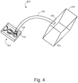
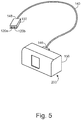
- Figs. 5 and 6 depict embodiments of an assisted breathing device 200 wherein the pressurized airflow source 150 is fluidly coupled to the fluidic diverter 100 via a tube 140, having a first end 146 coupled to the pressurized airflow source 150 and a second end 148 coupled to the inlet (not shown) of the fluidic diverter 100.
- the fluidic diverter 100 converts the pressurized airflow into two trains of pulses of pressurized air, which exit the fluidic diverter 100 via the outlets 120a and 120b, respectively.
- the fluidic diverter 100 is configured such that the outlets 120a and 120b are positioned proximate to a subject's nostrils to direct the trains of pulses of pressurized air into the nasal passageway of the subject without the need for a seal between the outlets 120a and 120b and the nasal passageway of the subject.
- a nasal cannula or mask is not required to apply positive airway pressure to the subject's upper respiratory tract.
- Fig. 6 depicts an embodiment of an assisted breathing device 200, wherein the outlets 120a and 120b are fluidly coupled to a nasal cannula 180 via first and second tubes 190.
- Each of the first and second tubes 190 has a first end 192 coupled to the outlet 120a or 120b, respectively, and a second end 194 coupled to the nasal cannula 180.
- the device 200 functions to avert respiratory tract occlusion even when a seal is not present between the nasal cannula 180 and the subject's nostrils.
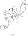
- Fig. 7 shows an exploded view of an embodiment of an assisted breathing device 200.
- a pressurized airflow source 150 is fluidly coupled to the actuator 105 via a tube 140 having a first end 146 fluidly coupled to the pressurized airflow source 150 and a second end 148 fluidly coupled to the inlet 110.
- the actuator comprises outlets 120a and 120b for discharging trains of pulses of pressurized air.
- the outlets 120a and 120b and the inlet 110 are fluidly coupled via the flowpath 130.
- a cover 172 is disposed on the actuator 105 to enclose the flowpath 130. In one embodiment, the cover 172 and the actuator 105 are fastened together to enclose the flowpath 130.
- Fig. 7 depicts an exemplary embodiment, wherein the actuator 105 and the cover 172 are secured via a plurality of screws 176 and threaded holes 174 for receiving the screws 176.
- First and second tubes 190 have a first end 192 that fluidly couples to the outlet 120a or 120b and a second end 194 that fluidly couples to the nasal cannula 180.
- the nasal cannula 180 is comprised of a chamber 184 fluidly coupled to a first prong 182a and a second prong 182b, wherein each of said prongs 182a and 182b is configured to be positioned proximate to a nostril of a subject.
- the chamber 184 is fluidly coupled to each of the first and second tubes 190.
- the nasal cannula 180 is configured to keep the two trains of vortices separated as they enter the nostrils of a subject.
- the nasal cannula 180 comprises a septum (not shown) for dividing the chamber 184 into a first compartment for receiving pulsatile airflow from the first tube 190 and a second compartment for receiving pulsatile airflow from the second tube 190.
- the first compartment of the cannula 180 is fluidly coupled to the first prong 182a and the second compartment is fluidly coupled to the second prong 182b.
- the nasal cannula 180 having a septum maintains two distinct trains of vortices, each entering a separate nostril of the user.
- the fluidic diverter 100 creates two streams of vortex airflow, i.e., two trains of pulses of pressurized air.
- Conventional jets of air or other fluid such as those used by existing ventilators and CPAP devices, produce a laminar flow of air that transitions into turbulent flow of air, which disperses very quickly as a free jet.
- the vortex airflow generated by embodiments of the present disclosure are defined by trains of vortices 170 that remain coherent in shape (i.e., the trains of vortices have a lower rate of dispersion) and produce high rates of the flow.
- the fluidic diverter 100 generates trains of vortices 170 as the airflow is diverted between the two outlets 120 of the fluidic diverter.
- Each vortex 170 then advects downstream under its own induced velocity. Based on the operating frequency of the fluidic diverter 100, this process can be repeated tens/hundreds/thousands of times per second. Patients may not be able to discern that the airflow is actually composed from a train of vortices 170, and may experience the trains of vortices 170 as if they were a continuous jet.
- the enhanced celerity of the trains of vortices 170 is associated with the ability of the flow to sustain high momentum (i.e., penetration of the flow) for longer distances.
- the vortices 170 that exit the outlets 120 or the nasal cannula 180 will enter the nostril and respiratory tract without significant reflection and/or loss to the environment.
- the pressurized airflow source 150 and the fluidic diverter 100 generate pressure (i.e., "power") that is sufficient to keep the passageways of the respiratory tract from collapsing and causing occlusion.
- Another advantage of the embodiments described herein is the ability to direct air pressures specifically to the occluded area of the respiratory tract.
- Use of trains of vortices 170 enables airstreams to be produced that will selectively flow to areas of greater resistance based on the principle of impedance matching.
- the coherent structure of the flow together with the ability to match the impedance of the trains of vortices 170 with the impedance of the airway (e.g., nasal passageways/respiratory tract), eliminates the need for a closed system that requires a mask.
- the impedance of the trains of pulses of pressurized air 170 may be matched to the impedance of the patient's airway (i.e., nasal passageways/respiratory tract).
- the maximum energy transfer occurs when the impedance of the source (input) matches the impedance of the load (output).
- Impedance is a general term used to describe resistance. While often associated with electric circuits, the concept of impedance is also applicable to the behavior of flow in fluid mechanics.
- the impedance of the flow in a system i.e., tube, channel, nasal cavities, etc.
- flow impedance is a function of frequency.
- impedance matching is a method used for maximizing power (energy) transfer of an electrical wave between a load and a source.
- impedance matching is a method used for maximizing the transfer of waves from one medium to the next with minimum loss to reflections.
- the impedance value of a nasal airway is patient-specific, and determined by the ratio of lung pressure and flow rate (i.e., velocity of the flow moving in the airway). When the impedance values are matched between a nasal airway and a vortex airflow, maximum flow is transferred from outside the nares into the nasal passageway, with minimal loss to reflections.
- the trains of vortices 170 are formed by passing a pressurized airflow 160 through the fluidic diverter.
- a frequency of the trains of vortices can be varied by adjusting factors such as the geometry of the actuator 105, the flowpath 130, and the input pressure of the airflow 160 from the airflow source 150.
- the impedance of the pressurized airflow 160 is directly related to the frequency of pulses and, thus, the fluidic diverter 100 described herein may produce trains of vortices 170 with varying impedance.
- the frequency of pulses of pressurized air ranges from about 1 Hz to about 50 kHz.
- a magnitude of a vortex of pressurized air is adjusted in the devices and methods disclosed herein by adjusting a magnitude of the airflow entering the fluidic diverter 100.
- a device for assisted breathing 200 according to Figs. 1-7 was built for evaluation purposes. Additionally, a 2:1 realistic nasal model 300 replica of the airway passage 204 from the nostrils 206 to the epiglottis 202 was constructed from CT scans taken along the upper nasal airway. A fluidic diverter 100 was placed at an approximate 10 mm standoff distance from the nostrils 206 of the nasal model 300. Its penetration (i.e., efficiency) was assessed by comparing the input and output (volume) flow rates with the aid of a probe 220. If airflow in the experiment were delivered as in current CPAP therapy (i.e., via a tight fitting mask), the input and output flow rates would have been equal because no flow would have leaked to the ambient.
- CPAP therapy i.e., via a tight fitting mask
- results indicate that when applying the vortex airflow at a small offset from the nares 206, more than 50% of input flow rate penetrated (i.e., was measured at the exit 202 of the model).
- the experiment also compared delivering continuous airflow using the same input conditions (i.e., applying airflow approximately 10 mm from the nares). Results showed that no more than 25% of the input flow rate penetrated into the model. Hence, in the absence of a mask, the majority of continuous airflow was lost to the ambient, while the vortex airflow was more than twice as likely to enter the airway model (compared with the continuous airflow).
- a method for assisting breathing in a subject in need thereof comprising passing a pressurized airflow through a fluidic diverter, wherein the fluidic diverter converts the pressurized airflow into pulses of pressurized air that are diverted alternately to provide a first train and a second train of pulses of pressurized air; and directing the first and second trains of pulses of pressurized air into a nasal passageway of a subject to assist breathing.
- the first and second trains of pulses of pressurized air enter the nasal passageway and avert respiratory tract occlusion, thereby treating obstructive sleep apnea.
- each of the pulses of pressurized air comprises a toroid vortex of pressurized air.
- the method further comprises generating the pressurized airflow by a compressor.
- a magnitude of the vortex of pressurized air is adjusted by adjusting a magnitude of the airflow entering the fluidic diverter.
- the first train of pulses of pressurized air exits the fluidic diverter via a first outlet
- the second train of pulses of pressurized air exits the fluidic diverter via a second outlet
- the first and second trains of pulses of pressurized air are directed into the nasal passageway of the subject by positioning the first outlet proximate to a first nostril of a subject and the second outlet proximate to a second nostril of the subject, without the use of a nasal cannula.
- the first and second trains of pulses of pressurized air are directed into the nasal passageway of the subject through a nasal cannula fluidly coupled to each of the first and second outlets of the fluidic diverter, wherein the nasal cannula is configured to be positioned proximate to the nostrils of the subject.
- a seal is not present or necessary between the nasal cannula and the nostrils of the subject in order to prevent airway occlusion.
- the nasal cannula is fluidly coupled to the first outlet via a first tube and is fluidly coupled to the second outlet via a second tube, wherein each of said first and second tubes delivers a train of pulses of pressurized air to the nasal passageway of the subject via the nasal cannula.
- the methods described herein further comprise matching a frequency of the pulses of pressurized air to an impedance of the nasal passageway.
- the frequency of the pulses of pressurized air ranges from about 1 Hz to about 50 kHz.
- a device for assisting breathing comprising: a compressor for providing a pressurized airflow; a fluidic diverter fluidly coupled to the compressor, the fluidic diverter comprising: an actuator comprising an inlet for receiving the pressurized airflow, a first outlet, and a second outlet; a flow path disposed on the actuator and fluidly coupled to the inlet and each of the first and second outlets; and a cover disposed on the actuator to enclose the flow path; wherein: the fluidic diverter converts the pressurized airflow into pulses of pressurized air diverted alternately into each of the first and second outlets; wherein the pulses of pressurized air exit the first and second outlets and enter a nasal passageway of a subject to assist breathing.
- each of said pulses of pressurized air comprises a toroid vortex of pressurized air.
- the devices disclosed herein do not require a seal between the first and second outlets and the nostrils and/or nasal passageway of the subject.
- the device further comprises a first tube having a first end and a second end, the first end coupled to the first outlet and the second end coupled to a nasal cannula; and a second tube having a first end and a second end, the first end coupled to the second outlet and the second end coupled to the nasal cannula, wherein the nasal cannula is configured to be positioned proximate to nostrils of a subject.
- the devices disclosed herein do not require a seal between the nasal cannula and the nostrils and/or nasal passageway of the subject.
- the nasal cannula comprises a chamber fluidly coupled to a first prong and a second prong, wherein each of said prongs is configured to be positioned proximate to a nostril of a subject.
- the nasal cannula comprises a septum for dividing the chamber into a first compartment for receiving pulses of pressurized air from the first tube and a second compartment for receiving pulses of pressurized air from the second tube, wherein the first compartment is fluidly coupled to the first prong and wherein the second compartment is fluidly coupled to the second prong.
- a frequency of the pulses of pressurized air is such that an impedance of the pulses of pressurized air is matched to an impedance of the nasal passageway.
- the device assists breathing in a subject suffering from obstructive sleep apnea by providing positive airway pressure to avert respiratory tract occlusion.
Landscapes
- Health & Medical Sciences (AREA)
- Emergency Medicine (AREA)
- Pulmonology (AREA)
- Engineering & Computer Science (AREA)
- Anesthesiology (AREA)
- Biomedical Technology (AREA)
- Heart & Thoracic Surgery (AREA)
- Hematology (AREA)
- Life Sciences & Earth Sciences (AREA)
- Animal Behavior & Ethology (AREA)
- General Health & Medical Sciences (AREA)
- Public Health (AREA)
- Veterinary Medicine (AREA)
- Otolaryngology (AREA)
- Measurement Of The Respiration, Hearing Ability, Form, And Blood Characteristics Of Living Organisms (AREA)
- Respiratory Apparatuses And Protective Means (AREA)
- Infusion, Injection, And Reservoir Apparatuses (AREA)
Claims (15)
- Dispositif pour aider la respiration, comprenant :un compresseur (150) pour fournir un flux d'air sous pression ;un déflecteur fluidique (100) couplé de manière fluide au compresseur, le déflecteur fluidique comprenant :un actionneur (105) comprenant une entrée pour recevoir le flux d'air sous pression, une première sortie (120a) et une seconde sortie (120b),une voie d'écoulement (130) placée sur l'actionneur et couplée de manière fluide à l'entrée et à chacune des première et seconde sorties ; etun couvercle placé sur l'actionneur pour englober la voie d'écoulement;dans lequel :
le déflecteur fluidique convertit le flux d'air sous pression en impulsions d'air sous pression déviées alternativement dans chacune des première et seconde sorties ; dans lequel les impulsions d'air sous pression sortent des première et seconde sortie s et entrent dans un passage nasal d'un sujet pour aider la respiration. - Dispositif selon la revendication 1, comprenant en outre :un premier tube ayant une première extrémité et une seconde extrémité, la première extrémité étant couplée à la première sortie et la seconde extrémité étant couplée à une canule nasale ; etun second tube ayant une première extrémité et une seconde extrémité, la première extrémité étant couplée à la seconde sortie et la seconde extrémité étant couplée à la canule nasale,dans lequel la canule nasale est conçue pour être positionnée à proximité des narines d'un sujet.
- Dispositif selon la revendication 2, dans lequel la canule nasale comprend une chambre couplée de manière fluide à une première broche et à une seconde broche, dans lequel chacune desdites broches est conçue pour être positionnée à proximité d'une narine d'un sujet.
- Dispositif selon la revendication 3, dans lequel la canule nasale comprend un septum pour diviser la chambre dans un premier compartiment pour recevoir les impulsions d'air sous pression du premier tube et un second compartiment pour recevoir les impulsions d'air sous pression du second tube, dans lequel le premier compartiment est couplé de manière fluide à la première broche et dans lequel le second compartiment est couplé de manière fluide à la seconde broche.
- Dispositif selon la revendication 1, dans lequel chacune desdites impulsions d'air sous pression comprend un vortex torique d'air sous pression.
- Dispositif selon la revendication 5, dans lequel une fréquence des impulsions d'air sous pression est telle qu'une impédance des impulsions d'air sous pression correspond à une impédance du passage nasal.
- Dispositif selon la revendication 1, dans lequel le dispositif aide la respiration chez un sujet atteint d'une apnée obstructive du sommeil en fournissant une pression positive dans les voies aériennes pour éviter une occlusion des voies respiratoires.
- Dispositif selon la revendication 1, dans lequel le dispositif ne nécessite pas une interface étanche entre les première et seconde sorties et le passage nasal du sujet.
- Dispositif selon la revendication 2, dans lequel le dispositif ne nécessite pas une interface étanche entre la canule nasale et les narines du sujet.
- Dispositif selon la revendication 6, dans lequel la fréquence des impulsions d'air sous pression varie d'environ 1 Hz à environ 50 kHz.
- Dispositif selon la revendication 1, dans lequel l'actionneur et le couvercle sont réalisés comme une structure unitaire pour englober la voie d'écoulement.
- Dispositif selon la revendication 1, dans lequel la voie d'écoulement comprend une région convergente couplée de manière fluide à l'entrée, une chambre placée entre la région convergente et les première et seconde sorties, et un premier et un second canal de retour, chacun desdits canaux de retour étant couplé de manière fluide à la chambre et à la région convergente, dans lequel le flux d'air sous pression passe au travers la région convergente et est dévié alternativement dans chacune des première et seconde sorties.
- Dispositif selon la revendication 12, dans lequel la transmission d'une partie du flux d'air alternativement entre les premier et second canaux de retour dévie le flux d'air alternativement dans chacune des première et seconde sorties.
- Dispositif selon la revendication 1, dans lequel le déflecteur fluidique est couplé de manière fluide au compresseur par un tube, dans lequel le compresseur comprend une machine de pression d'air positive continue (CPAP).
- Dispositif selon la revendication 1, dans lequel les impulsions d'air sous pression déviées alternativement dans chacune des première et seconde sorties comprennent des trains de vortex d'air dont la forme reste cohérente.
Applications Claiming Priority (2)
| Application Number | Priority Date | Filing Date | Title |
|---|---|---|---|
| US201662366697P | 2016-07-26 | 2016-07-26 | |
| PCT/US2017/043257 WO2018022448A1 (fr) | 2016-07-26 | 2017-07-21 | Dispositif et procédés comprenant un déflecteur fluidique pour aider la respiration |
Publications (3)
| Publication Number | Publication Date |
|---|---|
| EP3490651A1 EP3490651A1 (fr) | 2019-06-05 |
| EP3490651A4 EP3490651A4 (fr) | 2020-03-25 |
| EP3490651B1 true EP3490651B1 (fr) | 2021-09-01 |
Family
ID=61017183
Family Applications (1)
| Application Number | Title | Priority Date | Filing Date |
|---|---|---|---|
| EP17835018.7A Not-in-force EP3490651B1 (fr) | 2016-07-26 | 2017-07-21 | Dispositif comprenant un déflecteur fluidique pour aider la respiration |
Country Status (5)
| Country | Link |
|---|---|
| US (1) | US20190255269A1 (fr) |
| EP (1) | EP3490651B1 (fr) |
| JP (1) | JP2019525807A (fr) |
| CN (1) | CN109715239B (fr) |
| WO (1) | WO2018022448A1 (fr) |
Families Citing this family (3)
| Publication number | Priority date | Publication date | Assignee | Title |
|---|---|---|---|---|
| US12214139B2 (en) | 2018-11-02 | 2025-02-04 | University Of Cincinnati | Pulsating positive airway pressure devices and methods of use |
| CN111623505B (zh) * | 2020-05-25 | 2022-03-15 | 太原理工大学 | 一种自激振荡射流式增混换热出风装置 |
| CN115400307B (zh) * | 2022-08-23 | 2023-06-13 | 西安医学院第二附属医院 | 一种便于呼吸面罩更换的呼吸机 |
Family Cites Families (10)
| Publication number | Priority date | Publication date | Assignee | Title |
|---|---|---|---|---|
| US6595215B2 (en) * | 2000-03-13 | 2003-07-22 | Innomed Technologies, Inc. | Ventilation interface for sleep apnea therapy |
| US8528547B2 (en) * | 2007-04-02 | 2013-09-10 | Carefusion 2200, Inc. | High frequency oscillation respiratory therapy |
| US8833372B2 (en) * | 2007-05-29 | 2014-09-16 | Carefusion 207, Inc. | Integrated mask and prongs for nasal CPAP |
| US8371304B2 (en) * | 2007-12-28 | 2013-02-12 | Carefusion | Continuous positive airway pressure device and method |
| MX2010008200A (es) * | 2008-01-25 | 2011-03-15 | Salter Labs | Sistema para terapia respiratoria que incluye un ensamble de cánula nasal. |
| EP2113274B1 (fr) * | 2008-04-30 | 2016-04-27 | ResMed R&D Germany GmbH | Appareil pour l'administration contrôlée d'un gaz respiratoire aux voies respiratoires d'un utilisateur |
| WO2010115168A1 (fr) * | 2009-04-02 | 2010-10-07 | Breathe Technologies, Inc. | Procédés, systèmes et dispositifs de ventilation ouverte non vulnérante utilisant des buses d'apport de gaz prévues dans un tuyau extérieur |
| WO2013019717A1 (fr) * | 2011-07-29 | 2013-02-07 | University Of Cincinnati | Inducteurs de pression acoustique et méthodes de traitement de l'apnée obstructive du sommeil |
| JP6288861B2 (ja) * | 2012-05-22 | 2018-03-07 | コーニンクレッカ フィリップス エヌ ヴェKoninklijke Philips N.V. | 成形された気流による圧補助療法のためのシステム及び方法 |
| US10716908B2 (en) * | 2013-08-06 | 2020-07-21 | Fisher & Paykel Healthcare Limited | Infant CPAP device, interface and system |
-
2017
- 2017-07-21 EP EP17835018.7A patent/EP3490651B1/fr not_active Not-in-force
- 2017-07-21 US US16/318,482 patent/US20190255269A1/en not_active Abandoned
- 2017-07-21 JP JP2019503238A patent/JP2019525807A/ja active Pending
- 2017-07-21 WO PCT/US2017/043257 patent/WO2018022448A1/fr not_active Ceased
- 2017-07-21 CN CN201780055148.7A patent/CN109715239B/zh not_active Expired - Fee Related
Also Published As
| Publication number | Publication date |
|---|---|
| JP2019525807A (ja) | 2019-09-12 |
| EP3490651A1 (fr) | 2019-06-05 |
| CN109715239A (zh) | 2019-05-03 |
| EP3490651A4 (fr) | 2020-03-25 |
| CN109715239B (zh) | 2022-01-11 |
| WO2018022448A1 (fr) | 2018-02-01 |
| US20190255269A1 (en) | 2019-08-22 |
Similar Documents
| Publication | Publication Date | Title |
|---|---|---|
| US11154672B2 (en) | Methods, systems and devices for non-invasive ventilation including a non-sealing ventilation interface with an entrainment port and/or pressure feature | |
| EP2473220B1 (fr) | Système non effractif de ventilation nasale comprenant une interface non fermée avec espace libre pour l' injecteur | |
| US6253766B1 (en) | Continuous positive airway pressure therapy device | |
| US20150314098A1 (en) | Methods, systems and devices for non-invasive ventilation including a non-sealing ventilation interface with an entrainment port and/or pressure feature | |
| US20100252044A1 (en) | Continuous positive airway pressure device and method | |
| US8967143B2 (en) | Acoustic pressure inducers and methods for treatment of obstructive sleep apnea | |
| JP2013503720A5 (fr) | ||
| EP3490651B1 (fr) | Dispositif comprenant un déflecteur fluidique pour aider la respiration | |
| US20070144517A1 (en) | Breathing device | |
| CN109715236B (zh) | 在患者人工呼吸或支持呼吸期间呼吸控制施用粉末形式的气溶胶 | |
| US20240342419A1 (en) | Methods, systems and devices for non-invasive ventilation including a non-sealing ventilation interface with an entrainment port and/or pressure feature | |
| CN113164706B (zh) | 脉动呼吸道正压装置及其使用方法 | |
| JP2023536793A (ja) | 換気のためのデバイスおよび関連する方法 | |
| HK40103892A (zh) | 用於呼吸系统的通气口 |
Legal Events
| Date | Code | Title | Description |
|---|---|---|---|
| STAA | Information on the status of an ep patent application or granted ep patent |
Free format text: STATUS: THE INTERNATIONAL PUBLICATION HAS BEEN MADE |
|
| PUAI | Public reference made under article 153(3) epc to a published international application that has entered the european phase |
Free format text: ORIGINAL CODE: 0009012 |
|
| STAA | Information on the status of an ep patent application or granted ep patent |
Free format text: STATUS: REQUEST FOR EXAMINATION WAS MADE |
|
| 17P | Request for examination filed |
Effective date: 20190125 |
|
| AK | Designated contracting states |
Kind code of ref document: A1 Designated state(s): AL AT BE BG CH CY CZ DE DK EE ES FI FR GB GR HR HU IE IS IT LI LT LU LV MC MK MT NL NO PL PT RO RS SE SI SK SM TR |
|
| AX | Request for extension of the european patent |
Extension state: BA ME |
|
| DAV | Request for validation of the european patent (deleted) | ||
| DAX | Request for extension of the european patent (deleted) | ||
| A4 | Supplementary search report drawn up and despatched |
Effective date: 20200225 |
|
| RIC1 | Information provided on ipc code assigned before grant |
Ipc: A61M 16/08 20060101AFI20200219BHEP Ipc: A61M 16/00 20060101ALI20200219BHEP |
|
| GRAP | Despatch of communication of intention to grant a patent |
Free format text: ORIGINAL CODE: EPIDOSNIGR1 |
|
| STAA | Information on the status of an ep patent application or granted ep patent |
Free format text: STATUS: GRANT OF PATENT IS INTENDED |
|
| RIC1 | Information provided on ipc code assigned before grant |
Ipc: A61M 16/08 20060101AFI20210129BHEP Ipc: A61M 16/00 20060101ALI20210129BHEP |
|
| INTG | Intention to grant announced |
Effective date: 20210216 |
|
| GRAS | Grant fee paid |
Free format text: ORIGINAL CODE: EPIDOSNIGR3 |
|
| RAP3 | Party data changed (applicant data changed or rights of an application transferred) |
Owner name: UNIVERSITY OF CINCINNATI |
|
| RIN1 | Information on inventor provided before grant (corrected) |
Inventor name: KHOSLA, SID Inventor name: OREN, LIRAN Inventor name: GUTMARK, EPHRAIM |
|
| GRAA | (expected) grant |
Free format text: ORIGINAL CODE: 0009210 |
|
| STAA | Information on the status of an ep patent application or granted ep patent |
Free format text: STATUS: THE PATENT HAS BEEN GRANTED |
|
| AK | Designated contracting states |
Kind code of ref document: B1 Designated state(s): AL AT BE BG CH CY CZ DE DK EE ES FI FR GB GR HR HU IE IS IT LI LT LU LV MC MK MT NL NO PL PT RO RS SE SI SK SM TR |
|
| REG | Reference to a national code |
Ref country code: GB Ref legal event code: FG4D |
|
| REG | Reference to a national code |
Ref country code: CH Ref legal event code: EP Ref country code: AT Ref legal event code: REF Ref document number: 1425549 Country of ref document: AT Kind code of ref document: T Effective date: 20210915 |
|
| REG | Reference to a national code |
Ref country code: DE Ref legal event code: R096 Ref document number: 602017045370 Country of ref document: DE |
|
| REG | Reference to a national code |
Ref country code: IE Ref legal event code: FG4D |
|
| REG | Reference to a national code |
Ref country code: LT Ref legal event code: MG9D |
|
| REG | Reference to a national code |
Ref country code: NL Ref legal event code: MP Effective date: 20210901 |
|
| PG25 | Lapsed in a contracting state [announced via postgrant information from national office to epo] |
Ref country code: LT Free format text: LAPSE BECAUSE OF FAILURE TO SUBMIT A TRANSLATION OF THE DESCRIPTION OR TO PAY THE FEE WITHIN THE PRESCRIBED TIME-LIMIT Effective date: 20210901 Ref country code: BG Free format text: LAPSE BECAUSE OF FAILURE TO SUBMIT A TRANSLATION OF THE DESCRIPTION OR TO PAY THE FEE WITHIN THE PRESCRIBED TIME-LIMIT Effective date: 20211201 Ref country code: NO Free format text: LAPSE BECAUSE OF FAILURE TO SUBMIT A TRANSLATION OF THE DESCRIPTION OR TO PAY THE FEE WITHIN THE PRESCRIBED TIME-LIMIT Effective date: 20211201 Ref country code: RS Free format text: LAPSE BECAUSE OF FAILURE TO SUBMIT A TRANSLATION OF THE DESCRIPTION OR TO PAY THE FEE WITHIN THE PRESCRIBED TIME-LIMIT Effective date: 20210901 Ref country code: SE Free format text: LAPSE BECAUSE OF FAILURE TO SUBMIT A TRANSLATION OF THE DESCRIPTION OR TO PAY THE FEE WITHIN THE PRESCRIBED TIME-LIMIT Effective date: 20210901 Ref country code: HR Free format text: LAPSE BECAUSE OF FAILURE TO SUBMIT A TRANSLATION OF THE DESCRIPTION OR TO PAY THE FEE WITHIN THE PRESCRIBED TIME-LIMIT Effective date: 20210901 Ref country code: ES Free format text: LAPSE BECAUSE OF FAILURE TO SUBMIT A TRANSLATION OF THE DESCRIPTION OR TO PAY THE FEE WITHIN THE PRESCRIBED TIME-LIMIT Effective date: 20210901 Ref country code: FI Free format text: LAPSE BECAUSE OF FAILURE TO SUBMIT A TRANSLATION OF THE DESCRIPTION OR TO PAY THE FEE WITHIN THE PRESCRIBED TIME-LIMIT Effective date: 20210901 |
|
| REG | Reference to a national code |
Ref country code: AT Ref legal event code: MK05 Ref document number: 1425549 Country of ref document: AT Kind code of ref document: T Effective date: 20210901 |
|
| PG25 | Lapsed in a contracting state [announced via postgrant information from national office to epo] |
Ref country code: PL Free format text: LAPSE BECAUSE OF FAILURE TO SUBMIT A TRANSLATION OF THE DESCRIPTION OR TO PAY THE FEE WITHIN THE PRESCRIBED TIME-LIMIT Effective date: 20210901 Ref country code: LV Free format text: LAPSE BECAUSE OF FAILURE TO SUBMIT A TRANSLATION OF THE DESCRIPTION OR TO PAY THE FEE WITHIN THE PRESCRIBED TIME-LIMIT Effective date: 20210901 Ref country code: GR Free format text: LAPSE BECAUSE OF FAILURE TO SUBMIT A TRANSLATION OF THE DESCRIPTION OR TO PAY THE FEE WITHIN THE PRESCRIBED TIME-LIMIT Effective date: 20211202 |
|
| PG25 | Lapsed in a contracting state [announced via postgrant information from national office to epo] |
Ref country code: AT Free format text: LAPSE BECAUSE OF FAILURE TO SUBMIT A TRANSLATION OF THE DESCRIPTION OR TO PAY THE FEE WITHIN THE PRESCRIBED TIME-LIMIT Effective date: 20210901 |
|
| PG25 | Lapsed in a contracting state [announced via postgrant information from national office to epo] |
Ref country code: IS Free format text: LAPSE BECAUSE OF FAILURE TO SUBMIT A TRANSLATION OF THE DESCRIPTION OR TO PAY THE FEE WITHIN THE PRESCRIBED TIME-LIMIT Effective date: 20220101 Ref country code: SM Free format text: LAPSE BECAUSE OF FAILURE TO SUBMIT A TRANSLATION OF THE DESCRIPTION OR TO PAY THE FEE WITHIN THE PRESCRIBED TIME-LIMIT Effective date: 20210901 Ref country code: SK Free format text: LAPSE BECAUSE OF FAILURE TO SUBMIT A TRANSLATION OF THE DESCRIPTION OR TO PAY THE FEE WITHIN THE PRESCRIBED TIME-LIMIT Effective date: 20210901 Ref country code: RO Free format text: LAPSE BECAUSE OF FAILURE TO SUBMIT A TRANSLATION OF THE DESCRIPTION OR TO PAY THE FEE WITHIN THE PRESCRIBED TIME-LIMIT Effective date: 20210901 Ref country code: PT Free format text: LAPSE BECAUSE OF FAILURE TO SUBMIT A TRANSLATION OF THE DESCRIPTION OR TO PAY THE FEE WITHIN THE PRESCRIBED TIME-LIMIT Effective date: 20220103 Ref country code: NL Free format text: LAPSE BECAUSE OF FAILURE TO SUBMIT A TRANSLATION OF THE DESCRIPTION OR TO PAY THE FEE WITHIN THE PRESCRIBED TIME-LIMIT Effective date: 20210901 Ref country code: EE Free format text: LAPSE BECAUSE OF FAILURE TO SUBMIT A TRANSLATION OF THE DESCRIPTION OR TO PAY THE FEE WITHIN THE PRESCRIBED TIME-LIMIT Effective date: 20210901 Ref country code: CZ Free format text: LAPSE BECAUSE OF FAILURE TO SUBMIT A TRANSLATION OF THE DESCRIPTION OR TO PAY THE FEE WITHIN THE PRESCRIBED TIME-LIMIT Effective date: 20210901 Ref country code: AL Free format text: LAPSE BECAUSE OF FAILURE TO SUBMIT A TRANSLATION OF THE DESCRIPTION OR TO PAY THE FEE WITHIN THE PRESCRIBED TIME-LIMIT Effective date: 20210901 |
|
| REG | Reference to a national code |
Ref country code: DE Ref legal event code: R097 Ref document number: 602017045370 Country of ref document: DE |
|
| PLBE | No opposition filed within time limit |
Free format text: ORIGINAL CODE: 0009261 |
|
| STAA | Information on the status of an ep patent application or granted ep patent |
Free format text: STATUS: NO OPPOSITION FILED WITHIN TIME LIMIT |
|
| PG25 | Lapsed in a contracting state [announced via postgrant information from national office to epo] |
Ref country code: IT Free format text: LAPSE BECAUSE OF FAILURE TO SUBMIT A TRANSLATION OF THE DESCRIPTION OR TO PAY THE FEE WITHIN THE PRESCRIBED TIME-LIMIT Effective date: 20210901 Ref country code: DK Free format text: LAPSE BECAUSE OF FAILURE TO SUBMIT A TRANSLATION OF THE DESCRIPTION OR TO PAY THE FEE WITHIN THE PRESCRIBED TIME-LIMIT Effective date: 20210901 |
|
| 26N | No opposition filed |
Effective date: 20220602 |
|
| PG25 | Lapsed in a contracting state [announced via postgrant information from national office to epo] |
Ref country code: SI Free format text: LAPSE BECAUSE OF FAILURE TO SUBMIT A TRANSLATION OF THE DESCRIPTION OR TO PAY THE FEE WITHIN THE PRESCRIBED TIME-LIMIT Effective date: 20210901 |
|
| REG | Reference to a national code |
Ref country code: DE Ref legal event code: R119 Ref document number: 602017045370 Country of ref document: DE |
|
| PG25 | Lapsed in a contracting state [announced via postgrant information from national office to epo] |
Ref country code: MC Free format text: LAPSE BECAUSE OF FAILURE TO SUBMIT A TRANSLATION OF THE DESCRIPTION OR TO PAY THE FEE WITHIN THE PRESCRIBED TIME-LIMIT Effective date: 20210901 |
|
| REG | Reference to a national code |
Ref country code: CH Ref legal event code: PL |
|
| GBPC | Gb: european patent ceased through non-payment of renewal fee |
Effective date: 20220721 |
|
| REG | Reference to a national code |
Ref country code: BE Ref legal event code: MM Effective date: 20220731 |
|
| PG25 | Lapsed in a contracting state [announced via postgrant information from national office to epo] |
Ref country code: LU Free format text: LAPSE BECAUSE OF NON-PAYMENT OF DUE FEES Effective date: 20220721 Ref country code: LI Free format text: LAPSE BECAUSE OF NON-PAYMENT OF DUE FEES Effective date: 20220731 Ref country code: FR Free format text: LAPSE BECAUSE OF NON-PAYMENT OF DUE FEES Effective date: 20220731 Ref country code: CH Free format text: LAPSE BECAUSE OF NON-PAYMENT OF DUE FEES Effective date: 20220731 |
|
| PG25 | Lapsed in a contracting state [announced via postgrant information from national office to epo] |
Ref country code: GB Free format text: LAPSE BECAUSE OF NON-PAYMENT OF DUE FEES Effective date: 20220721 Ref country code: DE Free format text: LAPSE BECAUSE OF NON-PAYMENT OF DUE FEES Effective date: 20230201 Ref country code: BE Free format text: LAPSE BECAUSE OF NON-PAYMENT OF DUE FEES Effective date: 20220731 |
|
| P01 | Opt-out of the competence of the unified patent court (upc) registered |
Effective date: 20230613 |
|
| PG25 | Lapsed in a contracting state [announced via postgrant information from national office to epo] |
Ref country code: IE Free format text: LAPSE BECAUSE OF NON-PAYMENT OF DUE FEES Effective date: 20220721 |
|
| PG25 | Lapsed in a contracting state [announced via postgrant information from national office to epo] |
Ref country code: HU Free format text: LAPSE BECAUSE OF FAILURE TO SUBMIT A TRANSLATION OF THE DESCRIPTION OR TO PAY THE FEE WITHIN THE PRESCRIBED TIME-LIMIT; INVALID AB INITIO Effective date: 20170721 |
|
| PG25 | Lapsed in a contracting state [announced via postgrant information from national office to epo] |
Ref country code: MK Free format text: LAPSE BECAUSE OF FAILURE TO SUBMIT A TRANSLATION OF THE DESCRIPTION OR TO PAY THE FEE WITHIN THE PRESCRIBED TIME-LIMIT Effective date: 20210901 Ref country code: CY Free format text: LAPSE BECAUSE OF FAILURE TO SUBMIT A TRANSLATION OF THE DESCRIPTION OR TO PAY THE FEE WITHIN THE PRESCRIBED TIME-LIMIT Effective date: 20210901 |
|
| PG25 | Lapsed in a contracting state [announced via postgrant information from national office to epo] |
Ref country code: TR Free format text: LAPSE BECAUSE OF FAILURE TO SUBMIT A TRANSLATION OF THE DESCRIPTION OR TO PAY THE FEE WITHIN THE PRESCRIBED TIME-LIMIT Effective date: 20210901 |
|
| PG25 | Lapsed in a contracting state [announced via postgrant information from national office to epo] |
Ref country code: MT Free format text: LAPSE BECAUSE OF FAILURE TO SUBMIT A TRANSLATION OF THE DESCRIPTION OR TO PAY THE FEE WITHIN THE PRESCRIBED TIME-LIMIT Effective date: 20210901 |