EP3491982A1 - Bar blender - Google Patents
Bar blender Download PDFInfo
- Publication number
- EP3491982A1 EP3491982A1 EP17205174.0A EP17205174A EP3491982A1 EP 3491982 A1 EP3491982 A1 EP 3491982A1 EP 17205174 A EP17205174 A EP 17205174A EP 3491982 A1 EP3491982 A1 EP 3491982A1
- Authority
- EP
- European Patent Office
- Prior art keywords
- control button
- speed
- motor
- display element
- blender
- Prior art date
- Legal status (The legal status is an assumption and is not a legal conclusion. Google has not performed a legal analysis and makes no representation as to the accuracy of the status listed.)
- Withdrawn
Links
- 230000000007 visual effect Effects 0.000 claims abstract description 48
- 238000012545 processing Methods 0.000 claims description 4
- 230000000750 progressive effect Effects 0.000 claims description 4
- 235000013305 food Nutrition 0.000 claims description 2
- 230000000994 depressogenic effect Effects 0.000 description 16
- 230000006870 function Effects 0.000 description 16
- 230000001276 controlling effect Effects 0.000 description 9
- DCMURXAZTZQAFB-UHFFFAOYSA-N 1,4-dichloro-2-(2-chlorophenyl)benzene Chemical compound ClC1=CC=C(Cl)C(C=2C(=CC=CC=2)Cl)=C1 DCMURXAZTZQAFB-UHFFFAOYSA-N 0.000 description 6
- 238000013461 design Methods 0.000 description 5
- 230000004048 modification Effects 0.000 description 3
- 238000012986 modification Methods 0.000 description 3
- 238000013459 approach Methods 0.000 description 2
- 230000008859 change Effects 0.000 description 2
- 239000012530 fluid Substances 0.000 description 2
- 238000005259 measurement Methods 0.000 description 2
- 230000007246 mechanism Effects 0.000 description 2
- 239000000203 mixture Substances 0.000 description 2
- 238000012544 monitoring process Methods 0.000 description 2
- 230000003287 optical effect Effects 0.000 description 2
- 230000035807 sensation Effects 0.000 description 2
- QCVGEOXPDFCNHA-UHFFFAOYSA-N 5,5-dimethyl-2,4-dioxo-1,3-oxazolidine-3-carboxamide Chemical compound CC1(C)OC(=O)N(C(N)=O)C1=O QCVGEOXPDFCNHA-UHFFFAOYSA-N 0.000 description 1
- 241000234282 Allium Species 0.000 description 1
- 235000002732 Allium cepa var. cepa Nutrition 0.000 description 1
- 240000002234 Allium sativum Species 0.000 description 1
- 102000002322 Egg Proteins Human genes 0.000 description 1
- 108010000912 Egg Proteins Proteins 0.000 description 1
- 240000009164 Petroselinum crispum Species 0.000 description 1
- 229910000639 Spring steel Inorganic materials 0.000 description 1
- 230000009471 action Effects 0.000 description 1
- 230000003213 activating effect Effects 0.000 description 1
- 230000003321 amplification Effects 0.000 description 1
- 230000008901 benefit Effects 0.000 description 1
- 239000003086 colorant Substances 0.000 description 1
- 230000006835 compression Effects 0.000 description 1
- 238000007906 compression Methods 0.000 description 1
- 230000008878 coupling Effects 0.000 description 1
- 238000010168 coupling process Methods 0.000 description 1
- 238000005859 coupling reaction Methods 0.000 description 1
- 239000006071 cream Substances 0.000 description 1
- 230000009849 deactivation Effects 0.000 description 1
- 230000001419 dependent effect Effects 0.000 description 1
- 210000000969 egg white Anatomy 0.000 description 1
- 235000014103 egg white Nutrition 0.000 description 1
- 235000004611 garlic Nutrition 0.000 description 1
- 238000005286 illumination Methods 0.000 description 1
- 230000001939 inductive effect Effects 0.000 description 1
- 239000002184 metal Substances 0.000 description 1
- 238000002156 mixing Methods 0.000 description 1
- 238000003199 nucleic acid amplification method Methods 0.000 description 1
- 230000037361 pathway Effects 0.000 description 1
- 235000011197 perejil Nutrition 0.000 description 1
- 230000001105 regulatory effect Effects 0.000 description 1
- 239000000126 substance Substances 0.000 description 1
- 238000012360 testing method Methods 0.000 description 1
Images


Classifications
-
- A—HUMAN NECESSITIES
- A47—FURNITURE; DOMESTIC ARTICLES OR APPLIANCES; COFFEE MILLS; SPICE MILLS; SUCTION CLEANERS IN GENERAL
- A47J—KITCHEN EQUIPMENT; COFFEE MILLS; SPICE MILLS; APPARATUS FOR MAKING BEVERAGES
- A47J43/00—Implements for preparing or holding food, not provided for in other groups of this subclass
- A47J43/04—Machines for domestic use not covered elsewhere, e.g. for grinding, mixing, stirring, kneading, emulsifying, whipping or beating foodstuffs, e.g. power-driven
- A47J43/07—Parts or details, e.g. mixing tools, whipping tools
- A47J43/08—Driving mechanisms
- A47J43/082—Driving mechanisms for machines with tools driven from the upper side
-
- B—PERFORMING OPERATIONS; TRANSPORTING
- B01—PHYSICAL OR CHEMICAL PROCESSES OR APPARATUS IN GENERAL
- B01F—MIXING, e.g. DISSOLVING, EMULSIFYING OR DISPERSING
- B01F35/00—Accessories for mixers; Auxiliary operations or auxiliary devices; Parts or details of general application
- B01F35/20—Measuring; Control or regulation
- B01F35/22—Control or regulation
- B01F35/221—Control or regulation of operational parameters, e.g. level of material in the mixer, temperature or pressure
- B01F35/2214—Speed during the operation
- B01F35/22142—Speed of the mixing device during the operation
- B01F35/221422—Speed of rotation of the mixing axis, stirrer or receptacle during the operation
-
- A—HUMAN NECESSITIES
- A47—FURNITURE; DOMESTIC ARTICLES OR APPLIANCES; COFFEE MILLS; SPICE MILLS; SUCTION CLEANERS IN GENERAL
- A47J—KITCHEN EQUIPMENT; COFFEE MILLS; SPICE MILLS; APPARATUS FOR MAKING BEVERAGES
- A47J43/00—Implements for preparing or holding food, not provided for in other groups of this subclass
- A47J43/04—Machines for domestic use not covered elsewhere, e.g. for grinding, mixing, stirring, kneading, emulsifying, whipping or beating foodstuffs, e.g. power-driven
- A47J43/044—Machines for domestic use not covered elsewhere, e.g. for grinding, mixing, stirring, kneading, emulsifying, whipping or beating foodstuffs, e.g. power-driven with tools driven from the top side
- A47J2043/04409—Apparatus of hand held type
- A47J2043/04427—Apparatus of hand held type with housing extending vertically in line with the tool axis
Definitions
- This invention relates to bar blenders having a speed adjustment function.
- Bar blenders with a motor speed adjustment function are known from WO2015/078853A , in which a button on the handle can be depressed by the user, and the greater the movement of the button, the greater the speed setting of the motor.
- WO2010/012719A discloses a kitchen appliance in which a wheel in the handle controls the motor speed and a separate LED display controlled by a microprocessor indicates the motor speed.
- the purpose of the invention is to provide visual feedback of the current speed setting to the user in a simple and reliable manner.
- a bar blender comprising:
- the invention thus provides a simple and reliable mechanical way to show the user the current motor speed setting that corresponds to the position of the control button.
- the visual indication of the motor speed setting is based on and actually driven by the mechanical actuation of the control button, rather than by taking electrical measurements of for example voltage or current or by measuring the output speed at the motor shaft.
- a simple mechanical arrangement is provided for giving a speed setting indication.
- the display element may be a movable display element.
- the mechanical linkage may cause the movable display element to follow the control button as the latter is moved by the user.
- the movement and/or instantaneous position of the movable display element may then be indicative for the motor speed setting.
- the motor speed setting can be shown in a simple and reliable mechanical way without the need for any electrical circuitry or lights, or vibration or tone generators.
- the speed control circuit may comprise a travel sensing circuit, and the control button may be arranged to drive a travel element for controlling the travel sensing circuit to set the motor speed.
- a return spring such as a coil spring may be provided for biasing the control button to an initial button position corresponding to an end of the range of button positions and to a zero position for the motor speed indicated by the display element; the other end of the range of button positions and display positions corresponding to a maximum motor speed setting.
- the speed control circuit may be controlled to provide a step increase in speed when the control button is moved to its final position.
- the range of movement of the control button may be limited to at most 20mm, preferably at most 10mm.
- the control button is moved by pushing, thereby to depress the control button, but alternative arrangements are envisaged, such as rotary buttons and wheels.
- the visual display is preferably on an end surface of the housing remote from the blender blade, so that it is easily visible.
- the visual display may comprise a fixed cover through which the display element is visible.
- the visual display comprises an index, such as a printed or engraved icon or symbol, to indicate the speed setting.
- the display element may be arranged to move relative to a fixed display element to provide a variable display indicative of the motor speed setting.
- the movable display element and/or the fixed display element for example have a color pattern or line pattern such that the relative position of the movable display element provides a variable color or line pattern as the variable display.
- the amount of one color which is visible e.g. the color of the movable element which is different to the color of the fixed display element
- a movable edge line may provide a movable marking along a fixed scale.
- the mechanical linkage may comprise means for providing a predetermined, preferably non-unity, gearing ratio between the movements of the control button and of the display element. This facilitates the design of the visible display that operates over an easily visible range even when the range of actuation of the control button may be limited.
- the mechanical linkage may comprise meshing gears, and they may comprise a worm gear coupled to each of the moveable display element and the control button, and gears meshing with the worm gears to cause the control button to drive the movable display element with the predetermined gearing ratio.
- the gearing ratio may be from 1 to 3, for example from 1.5 to 2.5 i.e. preferably about 2.
- the visual display may be further adapted to provide the user with a continuous visual indication of the motor power consumption.
- the invention provides a bar blender comprising a tool, such as a blade, a whisking tool or the like, driven by a motor in a main housing.
- the main housing has a handle with a motor speed control button.
- a separate visual display on the housing shows the user the speed setting corresponding to the current position of the control button.
- the visual display is based on a mechanical linkage between the control button and the visual display.
- the mechanical linkage actuates the display element to provide the user with a visual indication of the current motor speed setting.
- the display element may be a movable display element. In such case, the mechanical linkage may causes the movable display element to follow the control button as it is moved by the user. This provides a simple and reliable feedback to the user.
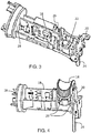
- Figure 1 shows a first example of bar blender in perspective view.
- the blender comprises a main housing 10 having a handle grip portion 12.
- a control button 14 is at the handle grip portion for controlling the motor speed.
- the control button 14 further controls the on-off actuation of the motor.
- a single control button 14 is provided for controlling motor actuation and speed.
- the on-off actuation may be controlled via a separate button.
- the control button comprises a push button 14, positioned at the location of the user's index finger when gripping the handle.
- a release button 15 enables fitted attachments such as a blending tool or whisking tool to be swapped over.
- Figure 2 shows the bar blender with a top cover removed to show the arrangement of internal components.
- the blender has a motor 16 within the main housing for driving a blender blade or other attachments.
- control circuit for the blender including circuitry mounted on a PCB 18 for controlling the motor speed.
- this circuitry includes a resistor circuit for providing an adjustable motor drive.
- This resistor circuit can comprise a chain of resistors connected in series, which results in a step type control.
- a slider is in contact with the resistors, and the movement of the slider results in selection of one of the resistors. This provides a discrete control approach.
- a directly analogous alternative is to use an analogue potentiometer.
- the control button 14 is mounted within a housing 20 which enables the control button 14 to slide relative to the housing.
- the control button 14 is carried by a carrier (although it should be understood that the carrier and control button can be a single integrated component).
- the control button 14 and its carrier form part of what is termed in this document a "control button arrangement".
- the control button can be considered to be the external feature which the user presses, and the carrier is the structure beneath.
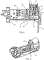
- FIG. 3 shows in more detail the housing 20 which carries the control button arrangement (and shows the control button removed).
- the housing forms a cradle for the control button and its carrier.
- a microswitch 22 functioning as a power switch. This is a switch which is actuated by very little physical force, typically through the use of a tipping point mechanism (otherwise known as an "over-center” mechanism). Switching takes place at specific and repeatable positions of the actuator and with a small amount of movement required between the different switch positions.
- the mains input cable 24 is electrically connected to the rest of the device through the power switch 22, so that the power switch 22 controls the supply of power to the remainder of the device, and thus functions (at least) as the power supply control for the motor.
- the mains cable 24 is to one side of the housing 20 (at the top end of the main housing), and the other side of the housing has a slot 26.
- the control button arrangement includes an electrical contact which slides up and down the slot 26 when the control button is moved. This electrical contact interfaces with electrical contact tracks on the PCB 18, which connect to the discrete resistors mentioned above. For this purpose, an edge of the PCB 18 is aligned with the slot 26 as shown.
- the motor is not shown in Figure 3 , but a motor support which fixes to the motor is shown as 28.
- FIG. 4 shows in more detail the control button arrangement mounted in its housing 20.
- the control button arrangement has retaining hooks 29 which clip the control button arrangement into the housing 20 thereby limiting the upward movement of the button.
- the downward movement is limited by a mechanical stop arrangement, which is engaged when the control button is fully depressed.
- Figure 5 shows a cross sectional view of the control button arrangement and its housing and shows the on/off function more clearly.
- control button 14 and its slidable carrier 40 can be seen more clearly.
- a base 42 of the carrier together with a corresponding part of the housing 20 define the mechanical stop mentioned above which limits the pressing-in of the control button 14.
- microswitch power switch 22.
- a spring loaded pin 44 is carried by the slidable carrier 40, beneath the control button 14, for mechanically engaging with the power switch when the control button is first depressed. This spring loaded pin functions as a first actuator for mechanically actuating the power switch when the control button is first depressed.
- the spring 45 of the spring loaded pin is located centrally inside the pin (which is hollow for this purpose) and biases the pin towards the power switch. The spring force is sufficient to activate the switch.
- the carrier 40 is biased into the non-depressed position by a return spring 46.
- this is arranged concentrically outside the spring 45 of the pin 44, to provide a compact arrangement.
- the spring loaded pin 44 is biased outwardly by the spring 45 and reaches a stop which means that it is just above the power switch when the carrier 40 is in the non-depressed position. There is a clearance of around 1mm as explained below.
- the pin 44 can retract and a sliding sleeve arrangement enables this.
- Figure 5 also shows more clearly the resistor circuit PCB contacts 50 and the contact element 52 carried by the carrier 40.
- the edge of the PCB 18 sits in the space between the two contacts 52. The relative position of the contacts 52 along the PCB edge determines which PCB tracks are electrically connected, which then determines the setting of the speed control circuit.
- FIG. 6 shows the speed control function of the control button more clearly.
- the PCB 18 has resistor tracks 50, and sliding contacts 52 are mounted to move with the carrier 40 and engage with the PCB tracks.
- the sliding contacts (of which there may be one or more) control the coupling of resistors. In this way, a circuit resistance is controlled in dependence on the control button position. This is then used in a motor control circuit, for example a transistor circuit with variable load depending on the resistor setting.
- the sliding contacts function as a second actuator for controlling the motor speed when the button is further depressed.
- This design makes use of a microswitch for the power on/off function.
- Speed setting resistors are connected by lead tracks on the PCB. This arrangement enables a minimum control button path length. The microswitch power switch is activated first, and the speed is regulated according to the subsequent path of the control button.
- the device After the power switch is activated, at first the device will not rotate. After a travelling distance of 2mm for example, the device starts rotating with speed setting 1. For an additional travelling distance of for example 1 mm, the speed remains at speed 1. After a total travelling distance of 3mm the slider 52 then switches to the next resistor and the speed is set to speed setting 2. The progressive movement of the carrier thus causes the speed control circuit to steps through the speed settings.
- the resistor tracks can be designed to provide a speed according to an arithmetic function in relation to the depression of the control button.
- the function could be linear, exponential, cascading or any other suitable function.
- the blender can further include a separate turbo boost switch.
- a turbo boost function can be implemented by the single switch, for example at the maximum movement (maximum depression) of the control button position.
- the turbo boost function can provide a step increase in speed when the control button is fully moved (e.g. fully depressed).
- the speed control enables selection of a speed from a set of speeds in a first range, or selection of a speed which is larger than the highest speed in the first range, and also a larger increase in speed compared to the difference in speed between any adjacent speeds in the first range.
- the switch slides along a predefined path of approximately 1 mm until the spring loaded pin contacts the micro-switch. This initial 1mm clearance provides a safety measure to ensure that the return spring does indeed disengage the power switch.
- the pin is preloaded with a spring-force to be able to immediately activate the micro-switch, which has a switching path of approximately 1 mm.
- the spring force of the spring loaded pin can be higher than the spring force of the return spring.
- the total path is approximately 2mm which is a desirable value based on bar-blender consumer application tests.
- this path length is less than 3mm, and it may be 2mm or less.
- the motor and its attached tool begin to rotate slowly.
- the user can further move the control button along its pathway for up to 8mm to adjust the required speed.
- the pin depresses 44 into the carrier 40 against the spring 45.
- the carrier meets mechanical stops. If a turbo boost function is provided, it can be enabled only when the control button is in this mechanically stopped fully depressed position.
- the switch When the user releases the control button, the switch is returned to the starting position and is disconnected from the power source by deactivation of the micro-switch.
- the total path length can in this example be kept to 10mm or less. It is generally preferred that this path length is less than 20mm.
- the example above makes use of a microswitch for the power switch.
- Figure 7 shows a first alternative implementation of the power switch, and shows cross sections taken at two perpendicular angles.
- the same reference numbers are used as in the first example for the same components.
- the switch again has a spring loaded pin 44 (the spring is not shown in Figure 7 ), but in this arrangement, the pin is for providing a short by directly contacting two spaced apart contact electrodes 70,72 at the base of the housing. This can provide an even more compact arrangement with fewer components.
- the spring force of the spring loaded pin is designed to ensure that reliable electrical contact is maintained.
- Figure 8 shows a second alternative implementation of the power switch.
- a pair of electrical contacts 80, 82 is provided laterally near the base of the housing.
- a shorting member 84 is mounted within the housing for shorting the contacts.
- the shorting member 84 is biased into a non-shorting position (as shown in Figure 8 ) by a spring steel configuration 86, and the shorting member is moved into contact with the pair of electrical contacts when the button is first depressed.
- the shorting member 84 is pushed against the contacts 80, 82 by a wedge 87, which engages with a face of the shorting member 84 when the button is depressed.
- the wedge 87 is part of the movable carrier 40 so moves down when the carrier is depressed.
- the spring bias of the shorting member 84 ensures that the electrical contact is broken when the button is released.
- the speed control is by moving a contact with respect to a resistor track arrangement.
- the speed control may be an actuator which engages with a speed control lever of a speed control circuit, rather than acting as the actual electrical contact.
- a discrete speed control circuit on the PCB such as a potentiometer circuit
- Other speed control modules may also be used instead of a resistor or potentiometer circuit.
- any travel sensing circuit can be used, which is then controlled by a travel element.
- the travel sensing circuit can for example be based on resistive, inductive or capacitive travel sensing. Further alternative travel sensing approaches include optical sensing or magnetic field sensing arrangements, in which movement results in a change of optical illumination or magnetic field.
- control button and its carrier slide in and out of the housing, and the control button is depressed by the user pushing the control button.
- the control button may instead pivot and still give essentially the same user experience.
- a further alternative is for the control button to slide horizontally (i.e. parallel with the surface of the outer housing) instead of vertically into and out of the housing volume.
- tactile or audible feedback may be desirable to provide tactile or audible feedback to the user, for example by providing a clicking sensation by vibrating the control button, or by providing a clicking sound or providing an indication at a display or with a light. This gives the user a sensation of greater control.
- Each click may correspond to a different potentiometer setting and therefore speed setting.
- the sound and tactile feedback can be achieved by providing a spring loaded metal contact which slides against a set of teeth when the control button is moved. The variation in force needed provides tactile feedback and also a sound can be in this way if desired.
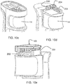
- the invention provides a mechanical form of visual feedback, in the modification of the bar blender shown in Figures 9 to 12 .
- the same numerals are used to denote corresponding elements of the bar blender throughout the drawings, and so will not be repeated.
- the modification is in the top portion of the blender, which links the control button to a visual display.
- the bar blender 100 embodying the invention has a visual display 103 forming the top portion of the main housing 10.
- a top cover 102 to the visual display 103 is flat and oval in this example and has a transparent elongate portion 104 forming a window visible by the user when the blender is held generally vertically in use.
- the visual display 103 is generally normal to the principal vertical axis of the main housing, so that its window 104 is also generally horizontal.
- the top cover 102 could be inclined, preferably up to 30 degrees to the horizontal, sloping downwards to the rear of the blender in use, which is the side of the cable 24, so that the window 104 remains clearly visible.
- the blender blade 101 or another tool such as a whisking tool, is clipped onto the lower end of the main housing and is releasable by activating the release button 15.
- FIG. 10a shows the top part of the blender without the top cover 102 and cable 24 and without an index plate 107 which is described below with reference to Figure 11 .
- a recess 109 accommodates the cable 24 which connects to the PCB 18 (not shown).
- a movable display element 105 in the form of a slider is guided horizontally by rails to slide between a fully retracted position as shown and a fully advanced position covering the cable recess 109.
- a spring e.g. a coil spring 106 in compression is positioned between a lug on the slider 105 and a fixed lug in the housing, to urge the slider to its retracted position, against the action of the control button as described below.
- a mechanical linkage 201, 202, 203, 204 and 205 allows the control button 14 to move the slider 105 directly, so that the position of the slider corresponds to the position of the control button, and therefore indicates the speed setting.
- a gearing ratio of 2 is provided by the teeth ratio (6:12) between gears 203 and 204 of a worm gear arrangement, so that the slider moves twice as far and twice as fast as the button.
- a horizontal worm gear 201 is connected to the top of the control button 14, and meshes with the gear 203 which is coaxial with and is connected to the gear 204.
- Gear 204 meshes with gear 205 which meshes with a horizontal worm gear 202 connected to the slider 105.
- the gearing ratio can be any convenient value, for example 1.5 to 3, but it is found that the gearing ratio 2 gives a suitable range of movement of the slider that is easily visible at the distance the bar blender is held away from the user's head. Even a gearing ratio of unity, i.e. with no travel length amplification, could still be workable.
- the end of the cable 24 is covered over its recess 109 and anchored by a plate (not shown) which carries an index plate 107 as shown in Figure 11 .
- the visual index on the plate is an icon in the form of an isosceles trapezoid divided into three sections, representing slow, medium and fast speeds, but other shapes are possible, and colors may be used that vary along the plate to denote speed.
- the slider 105 slides over the index plate 107 to obscure the index by an amount corresponding to the control button depression.
- the window 104 may be wide enough to reveal the whole width of the trapezoid 108 so that the width of the icon at the end edge of the slider 105 denotes the speed.
- the index is simply a set of parallel index lines across the width of the window.
- the slider is translucent to allow the lines to be seen, but the slider shows a color change. For example, a proportion of the index then appears to have a different color, and the index lines are still visible to provide a quantitative measure.
- the slider itself could bear an icon, the extent of the icon visible through the window then indicating speed, in which case there is no need for the index plate 108.
- the window 104 could comprise a screen including an index or icon through which the light reflected from the slider 105 is visible, so as to indicate speed according to the progression of the slider under the window.
- the visual display could instead be on another part of the main housing, remote from the control button 14 and still visible to a user operating the bar blender, with the mechanical linkage appropriately positioned to couple it to the button 14.
- the visual display represents the speed setting which has been set by the user's degree of depression of the control button. This may not necessarily represent the actual motor speed, which, depending upon the type of electric motor, may vary with the load on the blender tool or with temperature, and may depend on other factors. Nonetheless, this display has been found to give the user an immediate, clearly visible and reliable guide of the current speed setting to enable the user to vary the speed according to the condition of the mixture being blended. This could be for example to start whisking cream or egg-white slowly to prevent splashing and then smoothly accelerate; or to pulse with a slow speed when chopping onions or garlic, to prevent over processing; or to pulse with a medium speed when chopping parsley to get a finely cut result whilst preventing over processing.
- the position or stroke of the control button is used to provide an output to the user which represents the speed setting.
- the control button is for controlling speed - the greater the button is depressed, the greater the speed.
- control button in fact controls the power delivered to the motor.
- the speed which eventually results will depend on the mixture being processed. For example, a blender driven to full speed in low viscosity fluid will rotate faster than in thicker viscous fluid.
- the speed indication to the user is a relative indicator. For a given substance being blended (and while the viscosity remains the same), the speed indicator gives an indication of relative speed.
- the visual display may be further adapted to provide the user with a continuous visual indication of the motor power consumption. This may for example be provided as a power consumption scale provided adjacent the transparent elongate portion 104 (the window) so that a power level may be determined based on the position of the slider.
- the system as described above may be considered to provide a visual indication of an approximation to the blender speed, but the same system may be used to provide a more accurate indication of the power supply to the motor.
- a scale may be used which translates between the control button position and a power level based on the electrical and mechanical design of the blender.
- a kitchen appliance for example a bar blender
- a bar blender comprising:
- a manual speed control element i.e. a mechanical input device
- a mechanical input device is used to determine the power supplied, by using the mechanical actuation itself rather than by taking electrical measurements for example of voltage and/or current.
- a simple mechanical arrangement is provided for giving an electrical power indication.
- the manual speed control element may again comprise a control button located at the handle grip portion for progressive movement by a user over a predetermined continuous range to operate the speed control circuit to set the motor speed to one from a corresponding range of motor speeds
- the visual display may again comprise a movable display element for indicating the control button position over a predetermined range of positions indicative of the motor speed set by the user, and a mechanical linkage between the control button and the visual display to cause the movable display element to follow the control button as it is moved by the user thereby to provide the user with a continuous visual indication of the actual power supplied to the motor.
Landscapes
- Engineering & Computer Science (AREA)
- Mechanical Engineering (AREA)
- Food Science & Technology (AREA)
- Chemical & Material Sciences (AREA)
- Chemical Kinetics & Catalysis (AREA)
- Food-Manufacturing Devices (AREA)
Priority Applications (8)
| Application Number | Priority Date | Filing Date | Title |
|---|---|---|---|
| EP17205174.0A EP3491982A1 (en) | 2017-12-04 | 2017-12-04 | Bar blender |
| US16/768,942 US11534029B2 (en) | 2017-12-04 | 2018-11-22 | Bar blender |
| PL18803700.6T PL3720327T3 (pl) | 2017-12-04 | 2018-11-22 | Blender ręczny |
| JP2020529305A JP2021505227A (ja) | 2017-12-04 | 2018-11-22 | バーブレンダー |
| PCT/EP2018/082140 WO2019110311A1 (en) | 2017-12-04 | 2018-11-22 | Bar blender |
| CN201880088385.8A CN111698932B (zh) | 2017-12-04 | 2018-11-22 | 棒搅拌器 |
| RU2020122215A RU2782393C2 (ru) | 2017-12-04 | 2018-11-22 | Блендер с погружной насадкой |
| EP18803700.6A EP3720327B1 (en) | 2017-12-04 | 2018-11-22 | Bar blender |
Applications Claiming Priority (1)
| Application Number | Priority Date | Filing Date | Title |
|---|---|---|---|
| EP17205174.0A EP3491982A1 (en) | 2017-12-04 | 2017-12-04 | Bar blender |
Publications (1)
| Publication Number | Publication Date |
|---|---|
| EP3491982A1 true EP3491982A1 (en) | 2019-06-05 |
Family
ID=60569809
Family Applications (2)
| Application Number | Title | Priority Date | Filing Date |
|---|---|---|---|
| EP17205174.0A Withdrawn EP3491982A1 (en) | 2017-12-04 | 2017-12-04 | Bar blender |
| EP18803700.6A Active EP3720327B1 (en) | 2017-12-04 | 2018-11-22 | Bar blender |
Family Applications After (1)
| Application Number | Title | Priority Date | Filing Date |
|---|---|---|---|
| EP18803700.6A Active EP3720327B1 (en) | 2017-12-04 | 2018-11-22 | Bar blender |
Country Status (6)
| Country | Link |
|---|---|
| US (1) | US11534029B2 (pl) |
| EP (2) | EP3491982A1 (pl) |
| JP (1) | JP2021505227A (pl) |
| CN (1) | CN111698932B (pl) |
| PL (1) | PL3720327T3 (pl) |
| WO (1) | WO2019110311A1 (pl) |
Families Citing this family (8)
| Publication number | Priority date | Publication date | Assignee | Title |
|---|---|---|---|---|
| USD1056614S1 (en) | 2022-05-09 | 2025-01-07 | Sharkninja Operating Llc | Hand mixer |
| USD1020365S1 (en) | 2022-05-09 | 2024-04-02 | Sharkninja Operating Llc | Blender attachment |
| USD1050798S1 (en) * | 2022-05-09 | 2024-11-12 | Sharkninja Operating Llc | Mixer base |
| USD1050799S1 (en) | 2022-07-08 | 2024-11-12 | Sharkninja Operating Llc | Immersion blender |
| USD1070482S1 (en) | 2022-07-15 | 2025-04-15 | Sharkninja Operating Llc | Hand mixer |
| US20240330023A1 (en) * | 2023-03-28 | 2024-10-03 | Whirlpool Corporation | Adaptable user interface with tactile feedback |
| FR3154590B1 (fr) * | 2023-10-27 | 2025-11-07 | Seb Sa | Boîtier motorisé d’appareil de préparation culinaire comportant plusieurs vitesses de fonctionnement |
| CN118079773B (zh) * | 2024-04-28 | 2024-07-02 | 内蒙古塞克博科矿业科技有限公司 | 一种工业乳化油制备装置 |
Citations (7)
| Publication number | Priority date | Publication date | Assignee | Title |
|---|---|---|---|---|
| WO2007007448A1 (ja) * | 2005-07-07 | 2007-01-18 | Matsushita Electric Industrial Co., Ltd. | フードプロセッサー |
| WO2010012719A1 (de) | 2008-08-01 | 2010-02-04 | BSH Bosch und Siemens Hausgeräte GmbH | Küchengerät mit motordrehzahlanzeige |
| JP2011055934A (ja) * | 2009-09-08 | 2011-03-24 | Tiger Vacuum Bottle Co Ltd | 調理用電動撹拌機 |
| WO2011113082A1 (en) * | 2010-03-17 | 2011-09-22 | Breville Pty Limited | Stick mixer |
| WO2015078853A1 (en) | 2013-11-27 | 2015-06-04 | Koninklijke Philips N.V. | Kitchen appliances with speed control |
| CN204500411U (zh) * | 2015-03-25 | 2015-07-29 | 慈溪市乐泰电器有限公司 | 一种手持搅拌机 |
| EP3138450A1 (en) * | 2015-09-07 | 2017-03-08 | Huiyang Allan Plastics & Electric Industries Co., Limited | A hand-held blender |
Family Cites Families (9)
| Publication number | Priority date | Publication date | Assignee | Title |
|---|---|---|---|---|
| US3271013A (en) * | 1964-03-27 | 1966-09-06 | Sunbeam Corp | Mixer |
| US8529118B2 (en) | 2001-04-13 | 2013-09-10 | Sunbeam Products, Inc. | Blender cup with lid storage |
| US7854194B2 (en) | 2006-09-15 | 2010-12-21 | Breville Pty Limited | Juicer speed control |
| CN201070295Y (zh) * | 2007-08-28 | 2008-06-11 | 广东新宝电器股份有限公司 | 一种打蛋机 |
| EP2130469A1 (en) | 2008-06-06 | 2009-12-09 | Ian Geoffrey Wilson | Hand held blender with switch arrangement |
| CN201571983U (zh) * | 2009-11-21 | 2010-09-08 | 广东新宝电器股份有限公司 | 电子调速打蛋机 |
| CN202960204U (zh) * | 2012-12-20 | 2013-06-05 | 佛山市家乐仕电器有限公司 | 一种手持式搅拌器 |
| CN103230230B (zh) | 2013-03-26 | 2015-04-01 | 米技电子电器(上海)有限公司 | 手持式搅拌棒及其处理方法 |
| CN203953410U (zh) * | 2014-06-30 | 2014-11-26 | 广东新宝电器股份有限公司 | 手持式搅拌机的连杆调速传动装置 |
-
2017
- 2017-12-04 EP EP17205174.0A patent/EP3491982A1/en not_active Withdrawn
-
2018
- 2018-11-22 CN CN201880088385.8A patent/CN111698932B/zh active Active
- 2018-11-22 US US16/768,942 patent/US11534029B2/en active Active
- 2018-11-22 JP JP2020529305A patent/JP2021505227A/ja active Pending
- 2018-11-22 WO PCT/EP2018/082140 patent/WO2019110311A1/en not_active Ceased
- 2018-11-22 PL PL18803700.6T patent/PL3720327T3/pl unknown
- 2018-11-22 EP EP18803700.6A patent/EP3720327B1/en active Active
Patent Citations (7)
| Publication number | Priority date | Publication date | Assignee | Title |
|---|---|---|---|---|
| WO2007007448A1 (ja) * | 2005-07-07 | 2007-01-18 | Matsushita Electric Industrial Co., Ltd. | フードプロセッサー |
| WO2010012719A1 (de) | 2008-08-01 | 2010-02-04 | BSH Bosch und Siemens Hausgeräte GmbH | Küchengerät mit motordrehzahlanzeige |
| JP2011055934A (ja) * | 2009-09-08 | 2011-03-24 | Tiger Vacuum Bottle Co Ltd | 調理用電動撹拌機 |
| WO2011113082A1 (en) * | 2010-03-17 | 2011-09-22 | Breville Pty Limited | Stick mixer |
| WO2015078853A1 (en) | 2013-11-27 | 2015-06-04 | Koninklijke Philips N.V. | Kitchen appliances with speed control |
| CN204500411U (zh) * | 2015-03-25 | 2015-07-29 | 慈溪市乐泰电器有限公司 | 一种手持搅拌机 |
| EP3138450A1 (en) * | 2015-09-07 | 2017-03-08 | Huiyang Allan Plastics & Electric Industries Co., Limited | A hand-held blender |
Also Published As
| Publication number | Publication date |
|---|---|
| JP2021505227A (ja) | 2021-02-18 |
| EP3720327B1 (en) | 2025-04-09 |
| CN111698932A (zh) | 2020-09-22 |
| US20210161331A1 (en) | 2021-06-03 |
| CN111698932B (zh) | 2023-05-26 |
| US11534029B2 (en) | 2022-12-27 |
| RU2020122215A3 (pl) | 2022-03-30 |
| EP3720327A1 (en) | 2020-10-14 |
| WO2019110311A1 (en) | 2019-06-13 |
| RU2020122215A (ru) | 2022-01-10 |
| PL3720327T3 (pl) | 2025-06-09 |
Similar Documents
| Publication | Publication Date | Title |
|---|---|---|
| EP3720327B1 (en) | Bar blender | |
| EP3054825B2 (en) | Kitchen appliances with speed control | |
| US8922399B2 (en) | Force sensitive input devices and methods | |
| CA1331769C (en) | Wall-mountable switch and dimmer | |
| US20070216318A1 (en) | Traditional-opening dimmer switch having a multi-functional button | |
| EP3677998A1 (en) | Force sensitive input devices and methods | |
| DE102021201800B3 (de) | Tragbares Bediengerät zum Steuern eines Küchengeräts aus unterschiedlichen Bedienpositionen und Küchengerätesystem | |
| CN112313479B (zh) | 用于动力工具的致动器装置 | |
| CN1390688A (zh) | 食品切片机 | |
| WO2022180110A1 (de) | Tragbares bediengerät zum steuern eines küchengeräts aus unterschiedlichen bedienpositionen und küchengerätesystem | |
| DE102021201801B3 (de) | Tragbares Bediengerät zum Steuern eines Küchengeräts aus unterschiedlichen Bedienpositionen und Küchengerätesystem | |
| CA2486860A1 (en) | Stand mixer with control panel | |
| RU2782393C2 (ru) | Блендер с погружной насадкой | |
| CN219166196U (zh) | 烘焙设备速度控制装置 | |
| CN1330269C (zh) | 加热烹调装置 | |
| HK1217129B (zh) | 力敏输入装置及方法 |
Legal Events
| Date | Code | Title | Description |
|---|---|---|---|
| PUAI | Public reference made under article 153(3) epc to a published international application that has entered the european phase |
Free format text: ORIGINAL CODE: 0009012 |
|
| AK | Designated contracting states |
Kind code of ref document: A1 Designated state(s): AL AT BE BG CH CY CZ DE DK EE ES FI FR GB GR HR HU IE IS IT LI LT LU LV MC MK MT NL NO PL PT RO RS SE SI SK SM TR |
|
| AX | Request for extension of the european patent |
Extension state: BA ME |
|
| RAP1 | Party data changed (applicant data changed or rights of an application transferred) |
Owner name: KONINKLIJKE PHILIPS N.V. |
|
| STAA | Information on the status of an ep patent application or granted ep patent |
Free format text: STATUS: THE APPLICATION IS DEEMED TO BE WITHDRAWN |
|
| 18D | Application deemed to be withdrawn |
Effective date: 20191206 |