EP3492702A1 - Innengekühlte turbomaschinenkomponente - Google Patents
Innengekühlte turbomaschinenkomponente Download PDFInfo
- Publication number
- EP3492702A1 EP3492702A1 EP17204409.1A EP17204409A EP3492702A1 EP 3492702 A1 EP3492702 A1 EP 3492702A1 EP 17204409 A EP17204409 A EP 17204409A EP 3492702 A1 EP3492702 A1 EP 3492702A1
- Authority
- EP
- European Patent Office
- Prior art keywords
- flow
- row
- end wall
- sidewall
- turbomachine component
- Prior art date
- Legal status (The legal status is an assumption and is not a legal conclusion. Google has not performed a legal analysis and makes no representation as to the accuracy of the status listed.)
- Withdrawn
Links
Images


Classifications
-
- F—MECHANICAL ENGINEERING; LIGHTING; HEATING; WEAPONS; BLASTING
- F01—MACHINES OR ENGINES IN GENERAL; ENGINE PLANTS IN GENERAL; STEAM ENGINES
- F01D—NON-POSITIVE DISPLACEMENT MACHINES OR ENGINES, e.g. STEAM TURBINES
- F01D25/00—Component parts, details, or accessories, not provided for in, or of interest apart from, other groups
- F01D25/08—Cooling; Heating; Heat-insulation
- F01D25/12—Cooling
-
- F—MECHANICAL ENGINEERING; LIGHTING; HEATING; WEAPONS; BLASTING
- F01—MACHINES OR ENGINES IN GENERAL; ENGINE PLANTS IN GENERAL; STEAM ENGINES
- F01D—NON-POSITIVE DISPLACEMENT MACHINES OR ENGINES, e.g. STEAM TURBINES
- F01D5/00—Blades; Blade-carrying members; Heating, heat-insulating, cooling or antivibration means on the blades or the members
- F01D5/12—Blades
- F01D5/14—Form or construction
- F01D5/18—Hollow blades, i.e. blades with cooling or heating channels or cavities; Heating, heat-insulating or cooling means on blades
- F01D5/187—Convection cooling
-
- F—MECHANICAL ENGINEERING; LIGHTING; HEATING; WEAPONS; BLASTING
- F05—INDEXING SCHEMES RELATING TO ENGINES OR PUMPS IN VARIOUS SUBCLASSES OF CLASSES F01-F04
- F05D—INDEXING SCHEME FOR ASPECTS RELATING TO NON-POSITIVE-DISPLACEMENT MACHINES OR ENGINES, GAS-TURBINES OR JET-PROPULSION PLANTS
- F05D2230/00—Manufacture
- F05D2230/20—Manufacture essentially without removing material
- F05D2230/21—Manufacture essentially without removing material by casting
-
- F—MECHANICAL ENGINEERING; LIGHTING; HEATING; WEAPONS; BLASTING
- F05—INDEXING SCHEMES RELATING TO ENGINES OR PUMPS IN VARIOUS SUBCLASSES OF CLASSES F01-F04
- F05D—INDEXING SCHEME FOR ASPECTS RELATING TO NON-POSITIVE-DISPLACEMENT MACHINES OR ENGINES, GAS-TURBINES OR JET-PROPULSION PLANTS
- F05D2240/00—Components
- F05D2240/10—Stators
- F05D2240/11—Shroud seal segments
-
- F—MECHANICAL ENGINEERING; LIGHTING; HEATING; WEAPONS; BLASTING
- F05—INDEXING SCHEMES RELATING TO ENGINES OR PUMPS IN VARIOUS SUBCLASSES OF CLASSES F01-F04
- F05D—INDEXING SCHEME FOR ASPECTS RELATING TO NON-POSITIVE-DISPLACEMENT MACHINES OR ENGINES, GAS-TURBINES OR JET-PROPULSION PLANTS
- F05D2240/00—Components
- F05D2240/80—Platforms for stationary or moving blades
- F05D2240/81—Cooled platforms
-
- F—MECHANICAL ENGINEERING; LIGHTING; HEATING; WEAPONS; BLASTING
- F05—INDEXING SCHEMES RELATING TO ENGINES OR PUMPS IN VARIOUS SUBCLASSES OF CLASSES F01-F04
- F05D—INDEXING SCHEME FOR ASPECTS RELATING TO NON-POSITIVE-DISPLACEMENT MACHINES OR ENGINES, GAS-TURBINES OR JET-PROPULSION PLANTS
- F05D2250/00—Geometry
- F05D2250/70—Shape
- F05D2250/71—Shape curved
- F05D2250/711—Shape curved convex
-
- F—MECHANICAL ENGINEERING; LIGHTING; HEATING; WEAPONS; BLASTING
- F05—INDEXING SCHEMES RELATING TO ENGINES OR PUMPS IN VARIOUS SUBCLASSES OF CLASSES F01-F04
- F05D—INDEXING SCHEME FOR ASPECTS RELATING TO NON-POSITIVE-DISPLACEMENT MACHINES OR ENGINES, GAS-TURBINES OR JET-PROPULSION PLANTS
- F05D2250/00—Geometry
- F05D2250/70—Shape
- F05D2250/71—Shape curved
- F05D2250/712—Shape curved concave
-
- F—MECHANICAL ENGINEERING; LIGHTING; HEATING; WEAPONS; BLASTING
- F05—INDEXING SCHEMES RELATING TO ENGINES OR PUMPS IN VARIOUS SUBCLASSES OF CLASSES F01-F04
- F05D—INDEXING SCHEME FOR ASPECTS RELATING TO NON-POSITIVE-DISPLACEMENT MACHINES OR ENGINES, GAS-TURBINES OR JET-PROPULSION PLANTS
- F05D2260/00—Function
- F05D2260/20—Heat transfer, e.g. cooling
- F05D2260/201—Heat transfer, e.g. cooling by impingement of a fluid
-
- F—MECHANICAL ENGINEERING; LIGHTING; HEATING; WEAPONS; BLASTING
- F05—INDEXING SCHEMES RELATING TO ENGINES OR PUMPS IN VARIOUS SUBCLASSES OF CLASSES F01-F04
- F05D—INDEXING SCHEME FOR ASPECTS RELATING TO NON-POSITIVE-DISPLACEMENT MACHINES OR ENGINES, GAS-TURBINES OR JET-PROPULSION PLANTS
- F05D2260/00—Function
- F05D2260/20—Heat transfer, e.g. cooling
- F05D2260/221—Improvement of heat transfer
- F05D2260/2212—Improvement of heat transfer by creating turbulence
-
- F—MECHANICAL ENGINEERING; LIGHTING; HEATING; WEAPONS; BLASTING
- F05—INDEXING SCHEMES RELATING TO ENGINES OR PUMPS IN VARIOUS SUBCLASSES OF CLASSES F01-F04
- F05D—INDEXING SCHEME FOR ASPECTS RELATING TO NON-POSITIVE-DISPLACEMENT MACHINES OR ENGINES, GAS-TURBINES OR JET-PROPULSION PLANTS
- F05D2260/00—Function
- F05D2260/20—Heat transfer, e.g. cooling
- F05D2260/221—Improvement of heat transfer
- F05D2260/2214—Improvement of heat transfer by increasing the heat transfer surface
- F05D2260/22141—Improvement of heat transfer by increasing the heat transfer surface using fins or ribs
Definitions
- the present disclosure relates to an internally-cooled turbomachine component.
- turbomachine component which may be provided as an aerofoil component.
- Gas turbines generally include rows of stationary vanes fixed to the casing of the gas turbine and a rotor with a number of rows of rotating rotor blades fixed to a rotor shaft. Hot and pressurised working fluid flows through the rows of vanes and blades, thus imparting momentum to the rotor blades but also transferring a significant amount of heat to the vanes and blades in particular.
- Internally-cooled turbomachine components such as the vanes or blades, may include a cooling passage extending through the component.
- a cooling passage extending through the component.
- the pedestal bank comprises individual pedestals distributed in the cooling passage in a regular arrangement, because the absence of pedestals in a particular location generates a void which allows the cooling flow to circumvent certain pedestals or the pedestal bank altogether.
- a void may result in an overall reduction in cooling and may lead to increased temperature gradients.
- Such a void may be a particular concern in the region between the pedestal bank and a sidewall which bounds the cooling passage.
- half pedestals i.e. generally semi-cylindrical pedestals
- the half pedestals resemble the pedestals and so reduce the size of the void between the sidewall and the pedestal bank.
- cooling flow is distributed more evenly through the pedestal bank.
- an internally-cooled turbomachine component comprising: a main body (200) comprising; a first end wall (210), a second end wall (212) spaced apart from the first end wall (210), and a sidewall (220) which extends between the first end wall (210) and the second end wall (212) such that the first end wall (210), the second end wall (212) and the sidewall (220) define a cooling passage (230) extending between a fluid inlet (202) and a fluid outlet (204), a pedestal bank (240) comprising a plurality of pedestals (241) which span the cooling passage (230) between the first end wall (210) and the second end wall (212), wherein the pedestal bank (240) is spaced from the sidewall (220) to define a flow channel (250) therebetween; and a flow guide (260) for directing cooling flow away from the flow channel (250), the flow guide (260) extending from the flow channel (250) into the pedestal bank (240).
- the flow guide 260 is configured to redirect cooling flow within the cooling passage 230 and so draw peripheral flow F1 from the flow channel 250 into the pedestal bank 240.
- the flow guide 260 improves cooling by reducing the amount of cooling flow circumventing the pedestal bank 240 and reducing high temperature gradients about the flow channel 250.
- the pedestal bank (240) may comprise a first row (242) of pedestals, which is adjacent to and spaced apart from the sidewall (220), and a second row (244) of pedestals, which is spaced apart from the first row (242), the first row (242) located adjacent to the sidewall (220), and wherein the flow guide (260) extends from the first row (242) to the second row (244).
- the pedestal bank (240) may comprise a first column (246) of pedestals (241) and a second column (248) of pedestals, the pedestals (241) of each column (246, 248) generally aligned, and the first column (246) located upstream of the second column (248), and wherein the flow guide (260) extends from the first column (246) to the second column (248).
- the flow guide (260) may comprise a head portion (263), a tail portion (264), and an elongate middle portion (265) extending between the head portion (263) and the tail portion (264), and wherein the middle portion (265) is configured to define an inner side (266) facing the pedestal bank (240) and an outer side (267) facing the sidewall (220).
- the elongate middle portion (265) may extends a first distance in the flow direction (F1, F2, F3) and a second distance perpendicular to the flow direction (F1, F2, F3), wherein the first distance is equal to or greater than the second distance.
- a first section (268) of the inner side (266) may be concave.
- a second section (269) of the inner side (266) may be convex, the second section (269) provided closer to the tail portion (264) than the head portion section (263).
- the head portion (263) may be provided as a rounded end of the flow guide (260) and the tail portion (264) is provided as a pointed end of the flow guide (260), the tail portion (264) being located downstream of the head portion (263).
- the flow guide (260) may extend all of the way across the cooling passage (230) between the first end wall (210) and the second end wall (212).
- the flow guide (260) may be spaced apart from the sidewall (220).
- the sidewall (220) may be substantially planar.
- the turbomachine component may comprise a plurality of flow guides (260).
- the plurality of flow guides (260) is arranged as a first row (261) of flow guides (260) and a second row (262) of flow guides (260).
- the first row (261) of flow guides (260) may have a first spacing
- the second row (262) of flow guides may have a second spacing, wherein the first spacing is substantially equal to the second spacing and the first row (ref) of flow guides (260) is offset relative to the second row (262) of flow guides (260) by approximately half of the first spacing.
- the present disclosure relates to a component, for example a stator vane or a rotor blade, for use in a turbomachine, such as a gas turbine.
- Figures 1 and 2 show known arrangements to which features of the present disclosure may be applied.
- Figure 1 shows an example of a gas turbine engine 60 in a sectional view, which illustrates the nature of the stator vanes, the rotor blades and the environment in which they operate.
- the gas turbine engine 60 comprises, in flow series, an inlet 62, a compressor section 64, a combustion section 66 and a turbine section 68, which are generally arranged in flow series and generally in the direction of a longitudinal or rotational axis 70.
- the gas turbine engine 60 further comprises a shaft 72 which is rotatable about the rotational axis 70 and which extends longitudinally through the gas turbine engine 60.
- the rotational axis 70 is normally the rotational axis of an associated gas turbine engine. Hence any reference to "axial”, “radial” and “circumferential" directions are with respect to the rotational axis 70.
- the shaft 72 drivingly connects the turbine section 68 to the compressor section 64.
- air 74 which is taken in through the air inlet 62 is compressed by the compressor section 64 and delivered to the combustion section or burner section 66.
- the burner section 66 comprises a burner plenum 76, one or more combustion chambers 78 defined by a double wall can 80 and at least one burner 82 fixed to each combustion chamber 78.
- the combustion chambers 78 and the burners 82 are located inside the burner plenum 76.
- the compressed air passing through the compressor section 64 enters a diffuser 84 and is discharged from the diffuser 84 into the burner plenum 76 from where a portion of the air enters the burner 82 and is mixed with a gaseous or liquid fuel.
- the air/fuel mixture is then burned and the combustion gas 86 or working gas from the combustion is channelled via a transition duct 88 to the turbine section 68.
- the turbine section 68 may comprise a number of blade carrying discs 90 or turbine wheels attached to the shaft 72.
- the turbine section 68 comprises two discs 90 which each carry an annular array of turbine assemblies 12, which each comprises an aerofoil 14 embodied as a turbine blade 100 (shown in Figure 2 ).
- Turbine cascades 92 are disposed between the turbine blades 100.
- Each turbine cascade 92 carries an annular array of turbine assemblies 12, which each comprises an aerofoil 14 in the form of guiding vanes (i.e. stator vanes 96, shown in Figure 2 ), which are fixed to a stator 94 of the gas turbine engine 60.
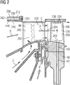
- FIG. 2 shows an enlarged view of a stator vane 96 and rotor blade 100.
- Arrows “A” indicate the direction of flow of combustion gas 86 past the aerofoils 96,100.
- Arrows “B” show air flow routes provided for sealing.
- Arrows “C” indicate cooling air flow paths through a flow inlet 202 to a flow outlet 204 via a cooling passage 230 in the stator vane 96.
- Cooling flow passages 101 may be provided in the rotor disc 90 which extend radially outwards to feed and air flow passage 103 the rotor blade 100.
- the air flow passages 103 feed a flow inlet 202 to a cooling passage 230 which exhausts at a flow outlet 204 which (in the example shown) is in the tip of the blade.
- a heatshield 140 which defines a part of the turbine flow path "A". It may also be provided with a flow inlet 202, cooling passage 230 and flow outlet 204 to promote cooling.
- the combustion gas 86 from the combustion chamber 78 enters the turbine section 68 and drives the turbine blades 100 which in turn rotate the shaft 72 to drive the compressor.
- the guiding vanes 96 serve to optimise the angle of the combustion or working gas 86 on to the turbine blades.
- Figure 3 shows a perspective view of an internally-cooled turbomachine component, such as a rotor blade 100, a stator vane 96 and/or heatshield 140 as shown in Figure 2 .
- an internally-cooled turbomachine component such as a rotor blade 100, a stator vane 96 and/or heatshield 140 as shown in Figure 2 .
- Each of the examples of a rotor blade 100, stator vane 96 and/or heatshield 140 comprises a main body 200 having a fluid inlet 202 and a fluid outlet 204.
- the terminology 'fluid inlet' and 'fluid outlet' may be taken to mean a single inlet and/or outlet, or a plurality of inlets and/or outlets, for example a plurality of apertures arranged to form a single inlet/outlet.
- the main body 200 comprises a first end wall 210 and a second end wall 212.
- the first end wall 210 and the second end wall 212 define opposite ends of the main body 200 along a first direction indicated by arrow "D" in Figure 3 .
- the first end wall 210 and second end wall 212 may be walls which define the suction side and pressure side of the aerofoil.
- the first end wall 210 and second end wall 212 may define radially inner and outer surfaces of the heatshield 140, as shown in Figure 2 .
- the main body 200 comprises a first sidewall 220 and second sidewall 222.
- the sidewalls 220, 222 are formed at either side of the main body 200 and thus define opposite sides of the main body 200 along a second direction, as indicated by arrow "E" in Figure 3 , which is perpendicular to the first direction "D".
- the first sidewall 220 and second sidewall 222 may define the leading edge or trailing edge, or (depending on the desired direction of flow) the tip or a platform, or form another part of an internal structure of the vane 96 or blade 100.
- the first sidewall 220 and second sidewall 222 may define circumferentially spaced apart edge walls the heatshield 140.
- first sidewall 220 which will be referred to as 'the sidewall 220' for ease of reference.
- the description applies equally to the second sidewall 222.
- the sidewall 220 is generally planar. That is to say, the sidewall 220 may as a whole be angled, inclined or curved relative to the other walls but there are no protrusions extending from or recesses extending into the sidewall 220 other than those described below.
- the plurality of walls 210, 212, 220, 222 is configured to define the internal cooling passage (or "chamber") 230 extending through the main body 200.
- the cooling passage 230 extends between the fluid inlet 202 and the fluid outlet 204.
- a height of the cooling passage 230 is defined along the first direction "D"
- a width of the cooling passage 230 is defined along the second direction "E”.
- a length of the cooling passage 230 is defined along a direction indicated by arrow "F" in Figure 3 , perpendicular to both the first direction "D” and the second direction "E".
- the cooling medium may comprise air.
- the cooling flow enters the cooling passage 230 through the fluid inlet 202, generally following a flow direction "F" (or 'third direction'), which is perpendicular to the first direction “D” and the second direction “E”, through the cooling passage 230, and ultimately exits through the fluid outlet 204.
- the flow direction is indicated by the arrows "F1", “F2", “F3”.
- a pedestal bank 240 is provided in the cooling passage 230 to optimise heat transfer between the main body 200 and the cooling flow.
- the pedestal bank 240 is configured to introduce serpentine flow paths and increase the surface area available for heat exchange.
- FIG 4 shows a partially broken-away perspective view of the main body 200.
- the pedestal bank 240 comprises a plurality of individual spaced-apart pedestals 241.
- the pedestals 241 are arranged in rows and columns, as illustrated in Figure 5 , including a first row 242, a second row 244, a first column 246 and a second column 248.
- the pedestals 241 of each row and column are generally provided in sequence or aligned.
- Each row and each column define approximately the same angle which, according to the present example, is approximately 90° (degrees angle).
- the first row 242 extends beside (or 'along') the sidewall 220, and is spaced apart from and immediately adjacent to the sidewall 220. That is to say, among the plurality of rows the first row 242 is closest to the sidewall 220. According to the present example, the first row 242 extends generally parallel to the sidewall 220.
- the second row 244 is immediately adjacent and closest to the first row 242, and extends beside and, as the case may be, parallel to the first row 242.
- the first column 246 and the second column 248 are arranged similarly. Thus each pedestal 241 is part of one row and one column.
- the pedestal bank 240 spans the cooling passage 230 between the first end wall 210 and the second end wall 212. That is, each pedestal 241 of the pedestal bank 240 extends in the first direction "D", extending all of the way from the first end wall 210 to the second end wall 212. In other words, the height of the pedestals 241 corresponds to the height of the cooling passage 230. Thus the serpentine flow paths are created by forcing the cooling flow impinging on the pedestal bank 240 around the individual pedestals 241.
- a flow channel 250 (or 'void') is formed between the sidewall 220 and the first row 242 of pedestals 241, which is adjacent to the sidewall 220.
- the void 250 is defined by the absence of features which may interrupt flow, for example pedestals 241 beside the sidewall 220 and/or half pedestals formed on the sidewall 220.
- the flow channel 250 is defined between the sidewall 220 and the pedestal bank 240.
- the pedestal bank 240 comprises columns 246, 248 which are offset relative to each other by half the pedestal spacing and, thus, the flow channel 250 possesses a maximal width Wmax and a minimal width Wmin.
- the maximal width Wmax may be equal to the spacing between adjacent pedestals 241 of the columns 246, 248 of the pedestal bank 240, and the minimal width Wmin may be about half the spacing between adjacent pedestals 241 of the columns 246, 248.
- a flow guide 260 is located in the cooling passage 230.
- the flow guide 260 is configured to redirect cooling flow F1, F2 within the cooling passage 260 and, in particular, configured to direct cooling flow from the flow channel 250 into the pedestal bank 240.
- pedestals 241 of the pedestal bank 240 are located upstream and/or downstream of the flow guide 260.
- the flow guide 260 is located between pedestals 241 located both upstream and downstream of the flow guide 260.
- the flow guide 260 spans the cooling passage 230 from the first end wall 210 to the second end wall 212, i.e. extends all the way from the first end wall 210 to the second end wall 212. In other words, the flow guide 260 has the height of the cooling passage 230.
- the flow guide 260 extends from the flow channel 250 into the pedestal bank 240. Accordingly, the flow guide 260 is elongate. According to the present example, the flow guide 260 spaced from the sidewall 220 without being provided in the flow channel 250. Instead the flow guide 260 extends from the vicinity of the flow channel 250 and extends into the pedestal bank 240.
- a plurality of flow guides 260 is provided in the cooling passage 230.
- Another flow guide 260 is provided downstream of the flow guide 260, with both flow guides separated by a pedestal 241.
- the plurality of flow guides 260 is arranged sequentially along the periphery of the pedestal bank 240 to define a first row 261 of flow guides 260.
- a second row 262 of flow guides 260 is also provided.
- a head portion (or 'first end') 263 of the flow guide 260 is located closer to the sidewall 220 than a tail portion (or 'second end') 264 of the flow guide 260.
- the flow guide 260 extends into the pedestal bank 240 and away from the sidewall 220.
- the flow guide 260 and the pedestal bank 240 have approximately the same separation to the sidewall 220. That is to say, the first row 242 of pedestals and the head portion 263 of the flow guide 260 are spaced from the sidewall 220 by approximately the same distance.
- the head portion 263 of the flow guide 260 is located at the periphery of the pedestal bank 240, while the tail portion 264 is located within the pedestal bank 240.
- a middle portion 265 of the flow guide 260 extends between the head portion 263 and the tail portion 264.
- the middle portion 265 is generally elongate.
- the elongate middle portion 265 extends a first distance in the third direction "F", and a second distance in the second direction "E", which corresponds to the width of the cooling passage 230. That is to say, the first distance of the middle portion 265 is along the cooling passage 230, while the second distance of the middle portion 265 is across the cooling passage 230.
- the first distance and the second distance are substantially equal. According to other examples, the first distance is greater than the second distance.
- the flow guide 260 possesses a length such that the flow guide 260 spans multiple rows 242, 244 of pedestals 241 and multiple columns 246, 248 of pedestals 241.
- the flow guide 260 may span at least two rows 242, 244 and two columns 246, 248.
- the flow guide 260 extends from the first row 242 of pedestals 241 to the second row 244 of pedestals 241, and from the first column 246 of pedestals 241 to the second column 248 of pedestals 241.
- the flow guide 260 may span two rows 242, 244 and/or two columns 246, 248.
- the flow guide 260 may span slightly more than two rows 242, 244 and/or two columns 246, 248.
- the flow guide 260 may span more than two rows 242, 244 and/or two columns 246, 248.
- the flow guide 260 extends from the first row 242 of pedestals 241 to the second row 244 of pedestals 241, and from the first column 246 of pedestals 241 to the second column 248 of pedestals 241.
- the middle portion 265 defines an inner side 266 of the flow guide 260 and an outer side 267 of the flow guide 260.
- the inner side 266 generally faces the pedestal bank 240, while the outer side 267 generally faces the sidewall 220.
- the sidewall 220 is located towards one side of the flow guide 260, i.e. towards the outer side 267, while the pedestal bank 240 is located towards the other side of the flow guide 260, i.e. towards the inner side 266.
- the middle portion 265 is generally straight so that the inner side 266 and outer side 267 are substantially straight.
- the head portion 263 is located at the periphery of the pedestal bank 240, and the tail portion 264 is located in the pedestal bank 240. According to other examples, the head portion 263 may be located in the flow channel 250, and/or the tail portion 264 may be located at the periphery of the pedestal bank 264.
- another row of flow guides 260 is provided to further optimise the cooling passage 230.
- the plurality of flow guides 260 is arranged into a first row of flow guides 260 and a second row of flow guides 270.
- the term 'row' is understood as in relation to the rows of the pedestal bank 240, in that the first row of flow guides is adjacent and closest to the sidewall 220.
- the second row of flow guides is adjacent to the first row of flow guides.
- the flow guides 260 of the first row and the flow guides 270 of the second row are provided in an interspaced arrangement. That is to say, a flow in the flow direction first encounters a member of one of the rows of flow guides, and subsequently a member of the other row of flow guides.
- the shape of the flow guide 260 is adapted to further optimise the cooling passage 230.
- the inner side 265 comprises a first section 268 and a second section 269.
- the first section 268 is concave.
- the second section 269 is convex, and provided closer to the tail portion 263 than the first portion 268.
- a cooling flow incident on the flow guide 260 first follows the concave first section 268 and then the convex second section 269 for optimised cooling flow.
- Figure 6 shows that the outer side 266 possesses a first section which is convex and a second section which is concave.
- the shape of the fluid guide 260 is adapted further in that the head portion 263 defines a rounded end, while the tail portion 264 defines a pointed end.
- the pointed end is a narrower portion of the flow guide 260 than the rounded end.
- the rounded end is provided upstream and configured to divide the incident cooling flow, whereas the pointed end is provided downstream and configured to recombine the cooling flow.
- a cooling flow F1, F2, F3 enters the cooling passage 230 through the fluid inlet 202, passes through the cooling passage 230, and exits the cooling passage 230 through the fluid outlet 204.
- the cooling flow separates into a central flow F2 through the pedestal bank 240 and a peripheral flow F1 through the flow channel 250.
- the flow guide 260 is configured to redirect the cooling flow into the pedestal bank 240.
- a portion of the central flow F2 is incident on the flow guide 260 and, thus, redirected from the head portion 263 of the flow guide 260 towards the tail portion 264.
- This generates a lower pressure region at the head portion 263.
- the lower pressure region draws peripheral flow F1 from the flow channel 250 towards the pedestal bank 240. That is to say, even where the flow guide 260 is not be located in the flow channel 250 or at the sidewall 220 or extends into the flow channel 250 or to the sidewall 220, the flow guide 260 nevertheless serves to redirect peripheral flow F1 from the flow channel 250 into the pedestal bank 240.
- the flow guide 260 draws cooling flow away from the sidewall 220 and out of the flow channel 250.
- the flow guide 260 directs some, but not all, of the flow passing along the flow channel 250 to the pedestal bank 240.
- the main body 200 is manufactured through a casting process using a ceramic core. Manufacturing through casting may be particularly common where the component is provided as an aerofoil and the main body 200 corresponds to a rotor blade or a stator vane.
- a ceramic core for casting the main body 200 possesses a planar side configured for forming the sidewall 220 of the main body 200. In particular, no grooves or notches extend along the full height of the planar sidewall which would otherwise be required for forming half pedestals. Accordingly, a ceramic core for casting the main body 200 may possess improved strength as well as a less complex shape than would otherwise be required when forming half pedestals.
- the ceramic core comprises a cavity configured to form the flow guide 260.
- the cavity corresponding to the flow guide 260 is formed similarly to cavities corresponding individual pedestals of the pedestal bank 240, but differs in shape and size as outlined above so as to configure the flow guide 260 for directing cooling flow through the cooling passage 230.
- the core may define fillet radii for forming connecting adjacent surfaces of the flow guides 260 and the end wall from which they extend.
- the flow guide 260 is configured to redirect cooling flow within the cooling passage 230. Even without being physically located in the flow channel 250, the flow guide 260 serves to draw peripheral flow F1 from the flow channel 250 to reduce the amount of cooling flow circumventing the pedestal bank 240. Thus improved cooling is achieved by the pedestal bank 240 and high temperature gradients in the region of the flow channel 250 are avoided.
- a ceramic core for casting may be structurally strengthened and so casting yield improved.
Landscapes
- Engineering & Computer Science (AREA)
- Mechanical Engineering (AREA)
- General Engineering & Computer Science (AREA)
- Turbine Rotor Nozzle Sealing (AREA)
Priority Applications (7)
| Application Number | Priority Date | Filing Date | Title |
|---|---|---|---|
| EP17204409.1A EP3492702A1 (de) | 2017-11-29 | 2017-11-29 | Innengekühlte turbomaschinenkomponente |
| EP18810911.0A EP3717747B1 (de) | 2017-11-29 | 2018-11-15 | Innengekühlte turbomaschinenkomponente |
| PCT/EP2018/081316 WO2019105743A1 (en) | 2017-11-29 | 2018-11-15 | Internally-cooled turbomachine component |
| CN201880077260.5A CN111406147B (zh) | 2017-11-29 | 2018-11-15 | 内部冷却型涡轮机械部件 |
| US16/764,998 US11098597B2 (en) | 2017-11-29 | 2018-11-15 | Internally-cooled turbomachine component |
| RU2020117507A RU2737270C1 (ru) | 2017-11-29 | 2018-11-15 | Компонент турбомашины с внутренним охлаждением |
| CA3081135A CA3081135C (en) | 2017-11-29 | 2018-11-15 | Internally-cooled turbomachine component |
Applications Claiming Priority (1)
| Application Number | Priority Date | Filing Date | Title |
|---|---|---|---|
| EP17204409.1A EP3492702A1 (de) | 2017-11-29 | 2017-11-29 | Innengekühlte turbomaschinenkomponente |
Publications (1)
| Publication Number | Publication Date |
|---|---|
| EP3492702A1 true EP3492702A1 (de) | 2019-06-05 |
Family
ID=60515213
Family Applications (2)
| Application Number | Title | Priority Date | Filing Date |
|---|---|---|---|
| EP17204409.1A Withdrawn EP3492702A1 (de) | 2017-11-29 | 2017-11-29 | Innengekühlte turbomaschinenkomponente |
| EP18810911.0A Active EP3717747B1 (de) | 2017-11-29 | 2018-11-15 | Innengekühlte turbomaschinenkomponente |
Family Applications After (1)
| Application Number | Title | Priority Date | Filing Date |
|---|---|---|---|
| EP18810911.0A Active EP3717747B1 (de) | 2017-11-29 | 2018-11-15 | Innengekühlte turbomaschinenkomponente |
Country Status (6)
| Country | Link |
|---|---|
| US (1) | US11098597B2 (de) |
| EP (2) | EP3492702A1 (de) |
| CN (1) | CN111406147B (de) |
| CA (1) | CA3081135C (de) |
| RU (1) | RU2737270C1 (de) |
| WO (1) | WO2019105743A1 (de) |
Families Citing this family (2)
| Publication number | Priority date | Publication date | Assignee | Title |
|---|---|---|---|---|
| US12031724B2 (en) * | 2022-05-05 | 2024-07-09 | General Electric Company | Turbine engine combustor having a combustion chamber heat shield |
| KR20250115097A (ko) * | 2024-01-23 | 2025-07-30 | 연세대학교 산학협력단 | 터빈 컴포넌트의 핀-휜 냉각 구조물 및 이를 포함하는 가스 터빈 |
Citations (3)
| Publication number | Priority date | Publication date | Assignee | Title |
|---|---|---|---|---|
| US4278400A (en) * | 1978-09-05 | 1981-07-14 | United Technologies Corporation | Coolable rotor blade |
| US20020021966A1 (en) * | 1999-10-05 | 2002-02-21 | Kvasnak William S. | Method and apparatus for cooling a wall within a gas turbine engine |
| US20090068021A1 (en) * | 2007-03-08 | 2009-03-12 | Siemens Power Generation, Inc. | Thermally balanced near wall cooling for a turbine blade |
Family Cites Families (18)
| Publication number | Priority date | Publication date | Assignee | Title |
|---|---|---|---|---|
| US6602047B1 (en) * | 2002-02-28 | 2003-08-05 | General Electric Company | Methods and apparatus for cooling gas turbine nozzles |
| US6832893B2 (en) * | 2002-10-24 | 2004-12-21 | Pratt & Whitney Canada Corp. | Blade passive cooling feature |
| US7014424B2 (en) * | 2003-04-08 | 2006-03-21 | United Technologies Corporation | Turbine element |
| US7131818B2 (en) * | 2004-11-02 | 2006-11-07 | United Technologies Corporation | Airfoil with three-pass serpentine cooling channel and microcircuit |
| US7478994B2 (en) * | 2004-11-23 | 2009-01-20 | United Technologies Corporation | Airfoil with supplemental cooling channel adjacent leading edge |
| EP2143883A1 (de) * | 2008-07-10 | 2010-01-13 | Siemens Aktiengesellschaft | Turbinenschaufel und entsprechender Gusskern |
| US9249675B2 (en) * | 2011-08-30 | 2016-02-02 | General Electric Company | Pin-fin array |
| US9127560B2 (en) * | 2011-12-01 | 2015-09-08 | General Electric Company | Cooled turbine blade and method for cooling a turbine blade |
| US9004866B2 (en) * | 2011-12-06 | 2015-04-14 | Siemens Aktiengesellschaft | Turbine blade incorporating trailing edge cooling design |
| US20130302179A1 (en) * | 2012-05-09 | 2013-11-14 | Robert Frederick Bergholz, JR. | Turbine airfoil trailing edge cooling hole plug and slot |
| US9599410B2 (en) * | 2012-07-27 | 2017-03-21 | General Electric Company | Plate-like air-cooled engine surface cooler with fluid channel and varying fin geometry |
| GB201217125D0 (en) * | 2012-09-26 | 2012-11-07 | Rolls Royce Plc | Gas turbine engine component |
| US9206695B2 (en) * | 2012-09-28 | 2015-12-08 | Solar Turbines Incorporated | Cooled turbine blade with trailing edge flow metering |
| US9228439B2 (en) * | 2012-09-28 | 2016-01-05 | Solar Turbines Incorporated | Cooled turbine blade with leading edge flow redirection and diffusion |
| US10247099B2 (en) * | 2013-10-29 | 2019-04-02 | United Technologies Corporation | Pedestals with heat transfer augmenter |
| EP3167160A1 (de) * | 2014-09-04 | 2017-05-17 | Siemens Aktiengesellschaft | Internes kühlsystem mit einsatz zur bildung von wandnahen kühlkanälen in einem hinteren kühlhohlraum einer gasturbinenschaufel mit wärmeableitenden rippen |
| EP3189214A1 (de) * | 2014-09-04 | 2017-07-12 | Siemens Aktiengesellschaft | Internes kühlsystem mit einsatz zur formung von nahwandigen kühlkanälen in den mittelgurtkühlhohlräumen einer gasturbinenschaufel |
| US20160230566A1 (en) * | 2015-02-11 | 2016-08-11 | United Technologies Corporation | Angled pedestals for cooling channels |
-
2017
- 2017-11-29 EP EP17204409.1A patent/EP3492702A1/de not_active Withdrawn
-
2018
- 2018-11-15 EP EP18810911.0A patent/EP3717747B1/de active Active
- 2018-11-15 CN CN201880077260.5A patent/CN111406147B/zh active Active
- 2018-11-15 US US16/764,998 patent/US11098597B2/en active Active
- 2018-11-15 WO PCT/EP2018/081316 patent/WO2019105743A1/en not_active Ceased
- 2018-11-15 RU RU2020117507A patent/RU2737270C1/ru active
- 2018-11-15 CA CA3081135A patent/CA3081135C/en active Active
Patent Citations (3)
| Publication number | Priority date | Publication date | Assignee | Title |
|---|---|---|---|---|
| US4278400A (en) * | 1978-09-05 | 1981-07-14 | United Technologies Corporation | Coolable rotor blade |
| US20020021966A1 (en) * | 1999-10-05 | 2002-02-21 | Kvasnak William S. | Method and apparatus for cooling a wall within a gas turbine engine |
| US20090068021A1 (en) * | 2007-03-08 | 2009-03-12 | Siemens Power Generation, Inc. | Thermally balanced near wall cooling for a turbine blade |
Also Published As
| Publication number | Publication date |
|---|---|
| CA3081135A1 (en) | 2019-06-06 |
| CA3081135C (en) | 2022-06-07 |
| CN111406147A (zh) | 2020-07-10 |
| RU2737270C1 (ru) | 2020-11-26 |
| US11098597B2 (en) | 2021-08-24 |
| EP3717747B1 (de) | 2022-03-02 |
| CN111406147B (zh) | 2023-04-07 |
| WO2019105743A1 (en) | 2019-06-06 |
| EP3717747A1 (de) | 2020-10-07 |
| US20200325782A1 (en) | 2020-10-15 |
Similar Documents
| Publication | Publication Date | Title |
|---|---|---|
| CN102171413B (zh) | 用于燃气涡轮发动机中过渡的倾斜出口 | |
| JP4659206B2 (ja) | 勾配付きフイルム冷却を備えるタービンノズル | |
| JP5503140B2 (ja) | 発散型タービンノズル | |
| US6932568B2 (en) | Turbine nozzle segment cantilevered mount | |
| CN102119268B (zh) | 燃气轮机中使用的具有带排气口的线性流动路径的过渡件 | |
| US10577944B2 (en) | Engine component with hollow turbulators | |
| EP3485147B1 (de) | Prallkühlung einer schaufelplattform | |
| US11624286B2 (en) | Insert for re-using impingement air in an airfoil, airfoil comprising an impingement insert, turbomachine component and a gas turbine having the same | |
| CN106988791A (zh) | 具有内带和外带冷却的涡轮喷嘴 | |
| JP2017075598A (ja) | 冷却流路冷却材排出プレナムを有するタービンノズル | |
| US11396818B2 (en) | Triple-walled impingement insert for re-using impingement air in an airfoil, airfoil comprising the impingement insert, turbomachine component and a gas turbine having the same | |
| KR102696566B1 (ko) | 가스 터빈 블레이드의 스퀄러 팁의 냉각 기술 | |
| CA3081135C (en) | Internally-cooled turbomachine component | |
| CN106968721B (zh) | 涡轮转子叶片中的内部冷却构造 | |
| US11905886B2 (en) | Heatshield for a gas turbine engine | |
| JP2019031973A (ja) | 不均一なシェブロンピンを備えたエンジン構成要素 | |
| EP3653839A1 (de) | Turbinenschaufel | |
| EP3492700A1 (de) | Innengekühlte turbomaschinenkomponente | |
| RU2790234C1 (ru) | Тепловой экран для газотурбинного двигателя | |
| EP3450683A1 (de) | Komponente und zugehöriges herstellungsverfahren | |
| WO2023095721A1 (ja) | タービン静翼 | |
| EP3470631A1 (de) | Hitzeschildvorrichtung | |
| WO2021246999A1 (en) | Ring segment for a gas turbine |
Legal Events
| Date | Code | Title | Description |
|---|---|---|---|
| PUAI | Public reference made under article 153(3) epc to a published international application that has entered the european phase |
Free format text: ORIGINAL CODE: 0009012 |
|
| STAA | Information on the status of an ep patent application or granted ep patent |
Free format text: STATUS: THE APPLICATION HAS BEEN PUBLISHED |
|
| AK | Designated contracting states |
Kind code of ref document: A1 Designated state(s): AL AT BE BG CH CY CZ DE DK EE ES FI FR GB GR HR HU IE IS IT LI LT LU LV MC MK MT NL NO PL PT RO RS SE SI SK SM TR |
|
| AX | Request for extension of the european patent |
Extension state: BA ME |
|
| STAA | Information on the status of an ep patent application or granted ep patent |
Free format text: STATUS: THE APPLICATION IS DEEMED TO BE WITHDRAWN |
|
| 18D | Application deemed to be withdrawn |
Effective date: 20191206 |