EP3492777B1 - Spannvorrichtung für einen zugmitteltrieb - Google Patents
Spannvorrichtung für einen zugmitteltrieb Download PDFInfo
- Publication number
- EP3492777B1 EP3492777B1 EP18205209.2A EP18205209A EP3492777B1 EP 3492777 B1 EP3492777 B1 EP 3492777B1 EP 18205209 A EP18205209 A EP 18205209A EP 3492777 B1 EP3492777 B1 EP 3492777B1
- Authority
- EP
- European Patent Office
- Prior art keywords
- sealing element
- base body
- tensioning
- sealing
- tensioning device
- Prior art date
- Legal status (The legal status is an assumption and is not a legal conclusion. Google has not performed a legal analysis and makes no representation as to the accuracy of the status listed.)
- Active
Links
Images




Classifications
-
- F—MECHANICAL ENGINEERING; LIGHTING; HEATING; WEAPONS; BLASTING
- F16—ENGINEERING ELEMENTS AND UNITS; GENERAL MEASURES FOR PRODUCING AND MAINTAINING EFFECTIVE FUNCTIONING OF MACHINES OR INSTALLATIONS; THERMAL INSULATION IN GENERAL
- F16H—GEARING
- F16H7/00—Gearings for conveying rotary motion by endless flexible members
- F16H7/08—Means for varying tension of belts, ropes or chains
- F16H7/10—Means for varying tension of belts, ropes or chains by adjusting the axis of a pulley
- F16H7/12—Means for varying tension of belts, ropes or chains by adjusting the axis of a pulley of an idle pulley
- F16H7/1254—Means for varying tension of belts, ropes or chains by adjusting the axis of a pulley of an idle pulley without vibration damping means
- F16H7/1281—Means for varying tension of belts, ropes or chains by adjusting the axis of a pulley of an idle pulley without vibration damping means where the axis of the pulley moves along a substantially circular path
-
- F—MECHANICAL ENGINEERING; LIGHTING; HEATING; WEAPONS; BLASTING
- F16—ENGINEERING ELEMENTS AND UNITS; GENERAL MEASURES FOR PRODUCING AND MAINTAINING EFFECTIVE FUNCTIONING OF MACHINES OR INSTALLATIONS; THERMAL INSULATION IN GENERAL
- F16H—GEARING
- F16H7/00—Gearings for conveying rotary motion by endless flexible members
- F16H7/08—Means for varying tension of belts, ropes or chains
- F16H7/10—Means for varying tension of belts, ropes or chains by adjusting the axis of a pulley
- F16H7/12—Means for varying tension of belts, ropes or chains by adjusting the axis of a pulley of an idle pulley
-
- F—MECHANICAL ENGINEERING; LIGHTING; HEATING; WEAPONS; BLASTING
- F02—COMBUSTION ENGINES; HOT-GAS OR COMBUSTION-PRODUCT ENGINE PLANTS
- F02B—INTERNAL-COMBUSTION PISTON ENGINES; COMBUSTION ENGINES IN GENERAL
- F02B67/00—Engines characterised by the arrangement of auxiliary apparatus not being otherwise provided for, e.g. the apparatus having different functions; Driving auxiliary apparatus from engines, not otherwise provided for
- F02B67/04—Engines characterised by the arrangement of auxiliary apparatus not being otherwise provided for, e.g. the apparatus having different functions; Driving auxiliary apparatus from engines, not otherwise provided for of mechanically-driven auxiliary apparatus
- F02B67/06—Engines characterised by the arrangement of auxiliary apparatus not being otherwise provided for, e.g. the apparatus having different functions; Driving auxiliary apparatus from engines, not otherwise provided for of mechanically-driven auxiliary apparatus driven by means of chains, belts, or like endless members
-
- F—MECHANICAL ENGINEERING; LIGHTING; HEATING; WEAPONS; BLASTING
- F16—ENGINEERING ELEMENTS AND UNITS; GENERAL MEASURES FOR PRODUCING AND MAINTAINING EFFECTIVE FUNCTIONING OF MACHINES OR INSTALLATIONS; THERMAL INSULATION IN GENERAL
- F16C—SHAFTS; FLEXIBLE SHAFTS; ELEMENTS OR CRANKSHAFT MECHANISMS; ROTARY BODIES OTHER THAN GEARING ELEMENTS; BEARINGS
- F16C33/00—Parts of bearings; Special methods for making bearings or parts thereof
- F16C33/72—Sealings
- F16C33/76—Sealings of ball or roller bearings
-
- F—MECHANICAL ENGINEERING; LIGHTING; HEATING; WEAPONS; BLASTING
- F16—ENGINEERING ELEMENTS AND UNITS; GENERAL MEASURES FOR PRODUCING AND MAINTAINING EFFECTIVE FUNCTIONING OF MACHINES OR INSTALLATIONS; THERMAL INSULATION IN GENERAL
- F16H—GEARING
- F16H7/00—Gearings for conveying rotary motion by endless flexible members
- F16H7/02—Gearings for conveying rotary motion by endless flexible members with belts; with V-belts
-
- F—MECHANICAL ENGINEERING; LIGHTING; HEATING; WEAPONS; BLASTING
- F16—ENGINEERING ELEMENTS AND UNITS; GENERAL MEASURES FOR PRODUCING AND MAINTAINING EFFECTIVE FUNCTIONING OF MACHINES OR INSTALLATIONS; THERMAL INSULATION IN GENERAL
- F16H—GEARING
- F16H7/00—Gearings for conveying rotary motion by endless flexible members
- F16H7/08—Means for varying tension of belts, ropes or chains
-
- F—MECHANICAL ENGINEERING; LIGHTING; HEATING; WEAPONS; BLASTING
- F16—ENGINEERING ELEMENTS AND UNITS; GENERAL MEASURES FOR PRODUCING AND MAINTAINING EFFECTIVE FUNCTIONING OF MACHINES OR INSTALLATIONS; THERMAL INSULATION IN GENERAL
- F16H—GEARING
- F16H7/00—Gearings for conveying rotary motion by endless flexible members
- F16H7/08—Means for varying tension of belts, ropes or chains
- F16H7/10—Means for varying tension of belts, ropes or chains by adjusting the axis of a pulley
- F16H7/12—Means for varying tension of belts, ropes or chains by adjusting the axis of a pulley of an idle pulley
- F16H7/1209—Means for varying tension of belts, ropes or chains by adjusting the axis of a pulley of an idle pulley with vibration damping means
- F16H7/1218—Means for varying tension of belts, ropes or chains by adjusting the axis of a pulley of an idle pulley with vibration damping means of the dry friction type
-
- F—MECHANICAL ENGINEERING; LIGHTING; HEATING; WEAPONS; BLASTING
- F16—ENGINEERING ELEMENTS AND UNITS; GENERAL MEASURES FOR PRODUCING AND MAINTAINING EFFECTIVE FUNCTIONING OF MACHINES OR INSTALLATIONS; THERMAL INSULATION IN GENERAL
- F16H—GEARING
- F16H7/00—Gearings for conveying rotary motion by endless flexible members
- F16H7/08—Means for varying tension of belts, ropes or chains
- F16H2007/0802—Actuators for final output members
- F16H2007/081—Torsion springs
-
- F—MECHANICAL ENGINEERING; LIGHTING; HEATING; WEAPONS; BLASTING
- F16—ENGINEERING ELEMENTS AND UNITS; GENERAL MEASURES FOR PRODUCING AND MAINTAINING EFFECTIVE FUNCTIONING OF MACHINES OR INSTALLATIONS; THERMAL INSULATION IN GENERAL
- F16H—GEARING
- F16H7/00—Gearings for conveying rotary motion by endless flexible members
- F16H7/08—Means for varying tension of belts, ropes or chains
- F16H2007/0842—Mounting or support of tensioner
-
- F—MECHANICAL ENGINEERING; LIGHTING; HEATING; WEAPONS; BLASTING
- F16—ENGINEERING ELEMENTS AND UNITS; GENERAL MEASURES FOR PRODUCING AND MAINTAINING EFFECTIVE FUNCTIONING OF MACHINES OR INSTALLATIONS; THERMAL INSULATION IN GENERAL
- F16H—GEARING
- F16H7/00—Gearings for conveying rotary motion by endless flexible members
- F16H7/08—Means for varying tension of belts, ropes or chains
- F16H2007/0863—Finally actuated members, e.g. constructional details thereof
- F16H2007/0865—Pulleys
-
- F—MECHANICAL ENGINEERING; LIGHTING; HEATING; WEAPONS; BLASTING
- F16—ENGINEERING ELEMENTS AND UNITS; GENERAL MEASURES FOR PRODUCING AND MAINTAINING EFFECTIVE FUNCTIONING OF MACHINES OR INSTALLATIONS; THERMAL INSULATION IN GENERAL
- F16H—GEARING
- F16H7/00—Gearings for conveying rotary motion by endless flexible members
- F16H7/08—Means for varying tension of belts, ropes or chains
- F16H2007/0889—Path of movement of the finally actuated member
- F16H2007/0893—Circular path
Definitions
- the invention relates to a tensioning device for a traction mechanism, which comprises an endless traction mechanism and at least two traction mechanism disks, one of which can function as a drive and one as an output of the traction mechanism.
- traction drives are used in particular on internal combustion engines of a motor vehicle to drive ancillary units, a first traction pulley being seated on the crankshaft of the internal combustion engine and driving the traction.
- Further traction drive pulleys are assigned to the auxiliary units, such as water pumps, alternators or air conditioning compressors, and are driven in rotation by the traction drive.
- auxiliary units such as water pumps, alternators or air conditioning compressors, and are driven in rotation by the traction drive.
- belts or chains are used as traction means and the traction means pulleys are designed to be complementary.
- the ancillary units are designed as consumers, that is, they are driven by the traction drive pulley of the crankshaft via the traction drive.
- the slack drum is formed between the crankshaft and the unit, usually the generator, which is adjacent in the direction of rotation of the traction mechanism.
- the traction mechanism is pretensioned by means of a tensioning element of the tensioning device.
- a tensioning element of the tensioning device is for example in the EP 2 573 423 B9 shown.
- the tensioning device comprises a housing part which is attached to a generator housing and forms an annular space.
- An annular tensioning part is rotatably mounted in the annular space of the housing part and is subjected to torque by means of a flat spiral spring, so that one can rotate on the Tensioning part mounted tensioning roller pretensions the belt.
- the end faces of the clamping part are coated with a polymer and designed as slide bearings. The polymer coating changes from the plain bearing into two opposing sealing lips, which run against the inner face of the annular space and seal the plain bearings from environmental influences.
- the clamping device has a housing in which two clamping arms are mounted pivotably about a common pivot axis. The clamping arms are supported against one another with spring means. Sealing elements are arranged between an outer axial disk of the base body and a first tensioning arm, the first tensioning arm and a second tensioning arm and between the second tensioning arm and a flange section, in each case for sealing the bearing arrangement.
- the present invention is based on the object of proposing a tensioning device for a traction drive which is easy to assemble and ensures a long service life, in particular for the sealing system and the bearing arrangement.
- a tensioning device for a traction drive is proposed, comprising the features of claim 1.
- the tensioning device has the advantage that the two sealing elements are permanently fixedly positioned relative to the carrier section due to the connection via the connecting webs. A displacement of the sealing elements in the radial direction or in the circumferential direction and in particular a complete detachment of the sealing sections from the carrier section is prevented, so that an increased service life of the sealing system and the resulting permanent sealing effect of the bearing arrangement results.
- the number of bores in the carrier section in which the connecting webs are arranged can be greater than 6, in particular greater than 12, and / or less than 24, in particular less than 18.
- the carrier section carries the seals and can be formed on one of the base body or the tensioning arm.
- the first sealing element and the second sealing element each comprise a closed profile ring and at least one sealing lip.
- the sealing lips in particular two sealing lips, rest on a sliding sealing surface which is assigned to the other part of the clamping arm or the base body, so that a space between the base body and the clamping arm is sealed from environmental influences on one side.
- the profile ring gives the sealing elements rigidity in the radial direction and circumferential direction and serves to connect the sealing element to a second component in a non-positive, positive and / or cohesive manner.
- the material from which the sealing rings are made can be from the group of thermoplastic elastomers, in particular thermoplastic elastomers based on urethane, or a vulcanized rubber material.
- the bearing elements are made of a different material than the sealing elements and, in one embodiment, can be made of a plastic based on polyamide or polyoxymethylene.
- the profile ring of the first sealing element is connected to the tensioning arm and the at least one sealing lip of the first sealing element rests on the base body, while the profile ring of the second sealing element is also connected to the tensioning arm and the at least one sealing lip of the second sealing element also rests on the base body.
- the profile ring of the first sealing element is connected to the base body and the at least one sealing lip of the first sealing element rests on the tensioning arm, while the profile ring of the second sealing element is also connected to the base body and the at least one sealing lip of the second sealing element is also on the Clamping arm is applied.
- the first and the second sealing element jointly seal a space in which the bearing arrangement of the clamping device is arranged.
- the first sealing element can be arranged in an annular first groove and the second sealing element in an annular second groove, the first groove and the second groove being provided in opposite support surfaces of the carrier section. Furthermore, the first sealing element can each be connected to the first axial bearing and the second sealing element to the second axial bearing in a form-fitting manner.
- the first sealing element and the first axial bearing as well as the second sealing element and the second axial bearing can each have a mutually complementary engagement structure.
- a non-contact seal can also be provided as a further seal for the bearing arrangement.
- the base body can have a first offset and the clamping arm a second offset, the first offset and the second offset being arranged and aligned radially outside of the first sealing element relative to the pivot axis, so that an S-shaped gap is formed between the base body and the clamping arm is.
- the gap acts as a filter for coarse dirt particles that have a larger diameter than the width of the annular gap, and protects the sealing elements from damage by these dirt particles.
- the gap acts as an axial labyrinth seal and can protect the installation space, which is formed by the base body and clamping arm and in which the seal and bearing arrangement is located, from the entry of fluids such as splash water.
- At least one of the first axial bearing and the second axial bearing can be designed in one piece with the radial bearing and form a bearing unit.
- the bearing unit can be connected to the base body or clamping arm, in particular the bearing unit can be connected to the base body or be molded onto the clamping arm.
- the bearing elements can be arranged both on the carrier section and on the part of the base body and clamping arm that does not have the carrier section.
- the spring means can comprise one or more spring elements, in particular in the form of a spiral spring, such as a helical and / or spiral spring.
- the spring means can also be referred to as a spring element or spring.
- At least one of the base body and the tensioning arm has at least one wear protection element in an area in which the spring means rest, which in particular is made of a plastic, for example the same material as the bearing elements, is made.
- a plastic for example the same material as the bearing elements
- coatings such as hard material layers, carbon layers or passivating layers can also be applied.
- FIG. 1 shows schematically a tensioning device 2 according to the invention for a traction drive in the configuration of a belt drive in the assembled state on an assembly 30.
- the tensioning device 2 and the assembly 30 form an assembly 35.
- the assembly 30 is designed as an alternator in the form shown, which has a housing 31 which can be attached to an engine block, not shown. It goes without saying, however, that the unit 30 can also be any other work machine that is part of the traction drive, for example a pump.
- the clamping device 2 is fastened on the front side to the housing 31 of the unit 30.
- a belt pulley 32 can be seen which is firmly connected to a drive shaft 34 of the unit 30 via a screw connection.
- a belt 33 wraps around the belt pulley 32 and a tensioning roller 6, which is rotatably mounted on a tensioning arm 4. The belt 33 is pretensioned by the tensioning roller 6.
- the Figures 2 to 6 which are jointly described below, show a clamping device 2 according to the invention in a first embodiment.
- the tensioning device comprises a base body 3, which can be connected to the housing 31 of the unit 30, a tensioning arm 4 which is pivotably mounted about a pivot axis A relative to the base body 3 and is resiliently supported on the base body 3 via spring means 5.
- the spring means 5 are in the present case designed as a helical spring, it being understood that any other spring elements can also be used, such as a spiral spring or a bow spring.
- the pivotable mounting of the clamping arm 4 takes place by means of a first axial bearing 7, which supports the clamping arm 4 in a first axial direction, a second axial bearing 8, which supports the clamping arm 4 in a second axial direction, and a radial bearing 9.
- the first axial bearing 7, the In the embodiment shown, the second axial bearing 8 and the radial bearing 9 are designed as a one-piece bearing unit 16 and are injection-molded onto a carrier section 41 of the tensioning arm 4.
- a first sealing element 10 and a second sealing element 11 are arranged radially on the outside on the carrier section 41.
- the first and the second sealing element 10, 11 are also molded directly onto the tensioning arm 4.
- the tensioning roller 6 is mounted on the tensioning arm 4 so as to be rotatable about an axis of rotation B which is parallel to the pivot axis A.
- the base body 3 comprises three radially outwardly protruding connection flanges 24 with bores through which connection elements for fastening to the unit 30 can be passed, a receiving section 36 and an axial disk 23.
- the axial disk 23 is firmly connected to the receiving section 36. This is done by flanging a sleeve attachment 37 of the receiving section 36 after the assembly of the spring element 5, the tensioning arm 4 with the bearing unit 16 connected to it and the sealing elements 10, 11, and the axial disk 23. Designs are also conceivable in which the axial disk over is connected to the receiving section 36 by a screw connection or by a press fit.
- the base body 3 has a first support surface 12 on the axial disk 23 and a second support surface 13 and a radial contact surface 14 on the receiving section 36, which together form a circumferential, largely C-shaped cross section and through which an outwardly open, circular installation space is partially limited in which the clamping arm 4 is arranged.
- the spring element 5 is supported with a spring end 25 on the side of the tensioning arm 4 on a contact shoulder 40 and with another spring end 25 'on the side of the base body 3 on a contact shoulder 40'.
- the spring element 5 thus acts on the tensioning arm 4 with a torque which restores the pivoting movement.
- the tensioning device 2 is mounted in a swiveled state in a belt drive, so that the restoring torque acts as a pretensioning force on the belt 33.
- the first axial bearing 7 is arranged between a first support surface 12 ′ of the tensioning arm 4 and the first support surface 12 of the base body 3.
- the second axial bearing 8 is arranged between a second support surface 13 ′ of the tensioning arm 4 and the second support surface 13 of the base body 3.
- the radial bearing 9 is arranged between a radial contact surface 14 ′ of the clamping arm 4 and a radial contact surface 14 of the base body 3.
- the first support surface 12 ', the second support surface 13' and the radial contact surface 14 ' are partially interrupted by recesses 26, which can be provided for the purpose of saving material.
- the first support surface 12 'and the second support surface 13' each lie in exactly one plane. It is also conceivable that the two surfaces are each composed of partial areas which are located in different parallel planes and are in particular separated from one another by shoulders.
- the first sealing element 10 and the second sealing element 11 are arranged radially on the outside of the bearing unit 16 and each comprise a profile ring 17, 17 'and two sealing lips 18, 18'.
- the first sealing element 10 sits with the profile ring 17 in a first annular groove 19 which is worked into the first support surface 12 'of the tensioning arm 4.
- the second sealing element 11 sits with the profile ring 17 ′ in a second annular groove 20 which is incorporated into the second support surface 13 ′ of the tensioning arm 4.
- the sealing lips 18 touch the first support surface 12, the sealing lips 18 'the second support surface 13 and thus jointly seal the space in which the bearing unit 16 is arranged.
- the one-piece bearing unit 16 consisting of a polyamide-based plastic, is first injection-molded onto the tensioning arm 4, the first axial bearing 7 and the second axial bearing 8 via connecting hollow cylinders 39 in bores 15 of the tensioning arm 4, which are located in the axial direction in the area of the carrier section 41 are arranged, are interconnected.
- the first sealing element 10 and the second sealing element 11, each consisting of a thermoplastic elastomer, are injection-molded onto or onto the semifinished product made up of clamping arm 4 and bearing unit 16 in a further process step.
- the first sealing element 10 and the second sealing element 11 are connected to one another via connecting webs 22 in the bores 15 of the tensioning arm 4. In the embodiment shown, the connecting webs 22 are guided through the connecting hollow cylinders 39.
- the two injection molding processes are carried out in such a way that only the connecting webs 22 are received in the bores 15.
- the embodiment shown comprises eighteen bores 15, which are distributed uniformly over a circumference in the carrier section 41 of the tensioning arm 4 and each receive a connecting hollow cylinder 39 and a connecting web 22. It goes without saying that a different number of connecting webs 22 can also be used.
- annular gap 29 is formed by a first offset 27 of the axial disk 23 and a second offset 28 of the clamping arm 4 and acts as a filter for coarse dirt particles and above all protects the sealing element 10, 11 from damage. Furthermore, the annular gap 29 acts like a labyrinth seal, which can restrict the entry of fluids, for example splash water, into the installation space in which the sealing elements 10, 11 and the bearing unit 16 are arranged.
- wear protection elements 21 are arranged in the contact areas on the base body 3 and the clamping arm 4.
- the wear protection elements 21 are designed as plastic inserts which can be exchanged as wear progresses.
- the wear protection elements 21 are made in particular from the same material as the bearing unit 16.
- the Figures 7 to 11 show a clamping device 2 according to the invention in a second embodiment.
- the clamping device comprises a base body 3, which can be connected to the housing 31 of the unit 30 by means of fastening means via three connecting flanges 24, a clamping arm 4 which is pivotably mounted about a pivot axis A relative to the base body 3 and is resiliently supported on the base body 3 via spring means 5 is.
- the spring means 5 are also designed here as helical springs, without being restricted to this.
- the pivoting mounting of the clamping arm 4 takes place by means of a first axial bearing 7, which supports the clamping arm 4 in a first axial direction, a second axial bearing 8, which supports the clamping arm 4 in a second axial direction, and a radial bearing 9.
- the first axial bearing 7 and the radial bearing 9 are designed as a one-piece bearing unit 16 which is injection molded onto a carrier section 41 of the base body 3.
- the second axial bearing 8 is a separate thrust washer.
- a first sealing element 10 and a second sealing element 11 are arranged radially on the outside on the carrier section 41.
- the sealing elements 10, 11 are injection molded directly onto the base body 3.
- the tensioning arm 4 has a tensioning roller 6, which is mounted rotatably about an axis of rotation B parallel to the pivot axis A, a receiving section 36 and an axial disk 23.
- the axial disk 23 is firmly connected to the receiving section 36. This is done by flanging a sleeve shoulder 37 of the receiving section 36 after the assembly of the spring element 5, the base body 4 with the bearing unit 16 connected to it and the sealing elements 10, 11, the second axial bearing 8 and the axial washer 23.
- the clamping arm 4 a first support surface 12 and a radial contact surface 14 on the receiving section 36 and a second support surface 13 on the axial disk 23, which together form a circumferential, largely C-shaped cross section and by which an outwardly open, circular installation space is partially limited, in which the base body 3 is arranged.
- the spring element 5 is supported with a spring end 25 on the side of the tensioning arm 4 on a contact shoulder 40 and with another spring end 25 'on the side of the Base body 3 on a contact shoulder 40 'from.
- the spring element 5 thus acts on the tensioning arm 4 with a torque which restores the pivoting movement.
- the tensioning device 2 is mounted in a swiveled state in a belt drive, so that the restoring torque acts as a pretensioning force on the belt 33.
- the first axial bearing 7 is arranged between the first support surface 12 of the tensioning arm 4 and a first support surface 12 ′ of the base body 3.
- the second axial bearing 8 is arranged between the second support surface 13 of the tensioning arm 4 and a second support surface 13 ′ of the base body 3.
- the radial bearing 9 is arranged between the radial contact surface 14 of the tensioning arm 4 and a radial contact surface 14 ′ of the base body 3.
- the first sealing element 10 and the second sealing element 11 are arranged radially on the outside of the bearing unit 16 and of the second axial bearing 8 and each comprise a profile ring 17, 17 'and two sealing lips 18, 18'.
- the first sealing element 10 sits with the profile ring 17 in a first annular groove 19 which is worked into the first support surface 12 ′ of the base body 3.
- the second sealing element 11 sits with the profile ring 17 ′ in a second annular groove 20 which is incorporated into the second support surface 13 ′ of the base body 3.
- the sealing lips 18 touch the first support surface 12 of the tensioning arm 4, the sealing lips 18 ′ touch the second support surface 13 of the tensioning arm 4 and thus jointly seal the space in which the bearing unit 16 and the second axial bearing 8 are arranged.
- the first sealing element 10 and the second sealing element 11 are injection-molded onto or onto the semi-finished product made up of the base body 3 and the bearing unit 16 in one process step.
- the first sealing element 10 and the second sealing element 11 are connected to one another via connecting webs 22 in the bores 15 of the base body 3.
- the embodiment shown comprises eighteen bores 15, which are distributed evenly over a circumference in the carrier section 41 of the base body 3. It goes without saying that a different number of connecting webs 22 can also be used.
- wear protection elements 21 are arranged in the contact areas on the base body 3 and the clamping arm 4.
- the wear protection elements 21 are designed as plastic inserts which can be exchanged as wear progresses.
Landscapes
- Engineering & Computer Science (AREA)
- General Engineering & Computer Science (AREA)
- Mechanical Engineering (AREA)
- Chemical & Material Sciences (AREA)
- Combustion & Propulsion (AREA)
- Devices For Conveying Motion By Means Of Endless Flexible Members (AREA)
- Sealing With Elastic Sealing Lips (AREA)
- Sliding-Contact Bearings (AREA)
- Sealing Of Bearings (AREA)
Description
- Die Erfindung betrifft eine Spannvorrichtung für einen Zugmitteltrieb, der ein endloses Zugmittel und zumindest zwei Zugmittelscheiben umfasst, von denen eine als Antrieb und eine als Abtrieb des Zugmitteltriebs fungieren kann. Derartige Zugmitteltriebe kommen insbesondere an Verbrennungsmotoren eines Kraftfahrzeugs zum Antreiben von Nebenaggregaten zum Einsatz, wobei eine erste Zugmittelscheibe auf der Kurbelwelle des Verbrennungsmotors sitzt und das Zugmittel antreibt. Weitere Zugmittelscheiben sind den Nebenaggregaten zugeordnet, wie beispielsweise Wasserpumpe, Lichtmaschine oder Klimaanlagenkompressor, und werden vom Zugmittelantrieb drehend angetrieben. Als Zugmittel werden in der Regel Riemen oder Ketten verwendet und die Zugmittelscheiben komplementär ausgestaltet.
- Bei herkömmlichen Zugmitteltrieben sind die Nebenaggregate als Verbraucher ausgelegt, das heißt sie werden von der Zugmittelscheibe der Kurbelwelle über das Zugmittel angetrieben. Dabei ist zwischen der Kurbelwelle und dem in Umlaufrichtung des Zugmittels benachbarten Aggregat, in der Regel der Generator, das Lostrum ausgebildet. Um hier eine ausreichende Umschlingung des Zugmittels um die Zugmittelscheibe zu gewährleisten, wird das Zugmittel mittels eines Spannelements der Spannvorrichtung vorgespannt. Eine solche Spannvorrichtung ist Beispielsweise in der
EP 2 573 423 B9 gezeigt. - Aus der
WO 2014/090417 ist eine weitere Spanneinrichtung für einen Riementrieb mit einem Spannarm bekannt. Die Spanneinrichtung umfasst ein Gehäuseteil, das an einem Generatorgehäuse befestigt ist und einen Ringraum bildet. Ein ringförmiges Spannteil ist drehbar im Ringraum des Gehäuseteils gleitgelagert und wird mittels einer ebenen Spiralfeder mit Drehmoment beaufschlagt, sodass eine drehbar auf dem Spannteil gelagerte Spannrolle den Riemen vorspannt. Die Stirnseiten des Spannteils sind mit einem Polymer beschichtet und als Gleitlager ausgebildet. Die Polymerbeschichtung geht vom Gleitlager in zwei gegenüberliegende Dichtlippen über, die an den Stirninnenseiten des Ringraums anlaufen und die Gleitlager vor Umwelteinflüssen abdichten. - Aus der
EP 3 023 670 B1 ist eine Spannvorrichtung für einen Riementrieb mit Starter-Generator bekannt. Die Spannvorrichtung weist ein Gehäuse auf, in dem zwei Spannarme um eine gemeinsame Schwenkachse schwenkbar gelagert sind. Die Spannarme sind mit Federmitteln gegeneinander abgestützt. Zwischen einer äußeren Axialscheibe des Grundkörpers und einem ersten Spannarm, dem ersten Spannarm und einem zweiten Spannarm sowie zwischen dem zweiten Spannarm und einem Flanschabschnitt sind jeweils zur Abdichtung der Lageranordnung Dichtungselemente angeordnet. - Der vorliegenden Erfindung liegt die Aufgabe zugrunde, eine Spannvorrichtung für einen Zugmitteltrieb vorzuschlagen, die einfach zu montieren ist und eine lange Lebensdauer insbesondere des Dichtungssystems und der Lageranordnung gewährleistet. Zur Lösung der Aufgabe wird eine Spannvorrichtung für einen Zugmitteltrieb vorgeschlagen, umfassend die Merkmale des Anspruchs 1.
- Die erfindungsgemäße Spannvorrichtung weist den Vorteil auf, dass die beiden Dichtungselemente durch die Verbindung über die Verbindungsstege dauerhaft ortsfest relativ zum Trägerabschnitt positioniert sind. Eine Verschiebung der Dichtungselemente in radialer Richtung oder in Umfangsrichtung und insbesondere ein vollständiges Lösen der Dichtungsabschnitte von dem Trägerabschnitt wird verhindert, sodass sich eine erhöhte Lebensdauer des Dichtungssystems und durch die resultierende dauerhafte Dichtwirkung auch der Lageranordnung ergibt. Dazu kann in einer möglichen Ausführungsform die Anzahl der Bohrungen im Trägerabschnitt, in denen die Verbindungsstege angeordnet sind, größer 6, insbesondere größer 12, und/oder kleiner 24, insbesondere kleiner 18 sein.
- Der Trägerabschnitt trägt die Dichtungen und kann an einem von dem Grundkörper oder dem Spannarm ausgebildet sein. Das erste Dichtungselement und das zweite Dichtungselement umfassen in einer Ausgestaltung jeweils einen geschlossenen Profilring und zumindest eine Dichtlippe. Die Dichtlippen, insbesondere zwei Dichtlippen, liegen an einer Gleitdichtfläche an, die dem anderen Teil von dem Spannarm oder dem Grundkörper zugeordnet ist, sodass ein Raum zwischen dem Grundkörper und dem Spannarm von einer Seite vor Umwelteinflüssen abgedichtet wird. Der Profilring verleiht dabei den Dichtungselementen in radialer Richtung und Umfangsrichtung Steifigkeit und dient dazu, das Dichtungselement mit einem zweiten Bauteil kraft-, form-, und/oder stoffschlüssig zu verbinden. Das Material aus denen die Dichtungsringe hergestellt sind, kann aus der Gruppe der Thermoplastischen Elastomere, insbesondere der Thermoplastischen Elastomere auf Urethanbasis, oder ein vulkanisierter Kautschukwerkstoff sein. Die Lagerelemente sind hingegen aus einem anderen Material als die Dichtungselemente hergestellt und können in einer Ausführungsform aus einem auf Polyamid oder Polyoxymethylen basierenden Kunststoff hergestellt sein.
- In einer möglichen Ausführungsform ist der Profilring des ersten Dichtungselements mit dem Spannarm verbunden und die zumindest eine Dichtlippe des ersten Dichtungselements liegt am Grundkörper an, während auch der Profilring des zweiten Dichtungselements mit dem Spannarm verbunden ist und die zumindest eine Dichtlippe des zweiten Dichtungselements ebenfalls am Grundkörper anliegt. In einer weiteren möglichen Ausführungsform ist der Profilring des ersten Dichtungselements mit dem Grundkörper verbunden und die zumindest eine Dichtlippe des ersten Dichtungselements liegt am Spannarm an, während auch der Profilring des zweiten Dichtungselements mit dem Grundkörper verbunden ist und die zumindest eine Dichtlippe des zweiten Dichtungselements ebenfalls am Spannarm anliegt. In beiden zuvor beschriebenen Ausführungsform dichten das erste und das zweite Dichtungselement gemeinsam einen Raum ab, in dem die Lageranordnung der Spannvorrichtung angeordnet ist.
- Zur Positionierung kann das erste Dichtungselement in einer ringförmigen ersten Nut und das zweite Dichtungselements in einer ringförmigen zweiten Nut angeordnet sein, wobei die erste Nut und die zweite Nut in entgegengesetzten Stützflächen des Trägerabschnitts vorgesehen sind. Des Weiteren können das erste Dichtungselement mit dem ersten Axiallager und das zweite Dichtungselement mit dem zweiten Axiallager jeweils formschlüssig verbunden sein. Hierzu können das erste Dichtungselement und das erste Axiallager sowie das zweite Dichtungselement und das zweite Axiallager jeweils eine gegenseitig komplementäre Eingriffsstruktur aufweisen.
- Als weitere Abdichtung der Lageranordnung kann zusätzlich eine berührungslose Dichtung vorgesehen sein. Hierfür kann der Grundkörper einen ersten Versatz und der Spannarm einen zweiten Versatz aufweisen, wobei der erste Versatz und der zweite Versatz bezogen auf die Schwenkachse radial außen vom ersten Dichtungselement angeordnet und gleichgerichtet sind, sodass zwischen dem Grundkörper und dem Spannarm ein S-förmiger Spalt gebildet ist. Der Spalt wirkt als Filter für grobe Schmutzpartikel, die einen größeren Durchmesser als die Breite des Ringspalts aufweisen, und schützt die Dichtungselemente vor Beschädigungen durch diese Schmutzpartikel. Des Weiteren wirkt der Spalt als axiale Labyrinthdichtung und kann den Bauraum, der von Grundkörper und Spannarm gebildet wird und in dem sich die Dichtungs- und Lageranordnung befindet, vor dem Eintritt von Fluiden wie Spritzwasser schützen.
- Zur schwenkbaren Lagerung des Spannarms kann zumindest eines von dem ersten Axiallager und dem zweiten Axiallager einteilig mit dem Radiallager ausgeführt sein und eine Lagereinheit bilden. Die Lagereinheit kann mit dem Grundkörper oder Spannarm verbunden sein, insbesondere kann die Lagereinheit an den Grundkörper oder den Spannarm angespritzt sein. Die Lagerelemente können sowohl an dem Trägerabschnitt angeordnet sein als auch an dem Teil von Grundkörper und Spannarm, das nicht den Trägerabschnitt aufweist. Eine Integration der einzelnen Lagerelemente in ein Bauteil reduziert während der Montage der Spannvorrichtung die Komplexität, sodass die Wahrscheinlichkeit von Montagefehlern verringert wird.
- Die Federmittel können ein oder mehrere Federelemente umfassen, insbesondere in Form einer Biegefeder, wie beispielsweise eine Schrauben- und/oder Spiralfeder. Die Federmittel können auch als Federelement oder Feder bezeichnet werden. Bei wechselnder Belastung, wie sie auf die Spannvorrichtung einwirkt, führen die Federmittel in radialer Richtung bezüglich ihrer Längsachse Bewegungen aus. In den Bereichen in denen die Federmittel auf dem Grundköper bzw. dem Spannarm aufliegen kann es durch diese Bewegungen zu Verschleiß und struktureller Schwächung der Federmittel kommen. Um den resultierenden schädigenden Effekt zu minimieren, kann in einer möglichen Ausgestaltung vorgesehen sein, dass zumindest eines von Grundkörper und Spannarm in einem Bereich, in dem die Federmittel anliegen, zumindest ein Verschleißschutzelement aufweist, das insbesondere aus einem Kunststoff, beispielweise aus dem gleichen Material wie die Lagerelemente, hergestellt ist. Neben Kunststoffeinsätzen können auch Beschichtungen wie beispielsweise Hartstoffschichten, Kohlenstoffschichten oder passivierende Schichten aufgebracht werden.
- Bevorzugte Ausführungsbeispiele werden nachstehend anhand der Zeichnungsfiguren erläutert. Hierin zeigt
- Figur 1
- eine schematische Darstellung einer erfindungsgemäßen Spannvorrichtung in einem montierten Zustand in einem Zugmitteltrieb in einer perspektivischen Ansicht;
- Figur 2
- eine erfindungsgemäße Spannvorrichtung in einer ersten Ausführungsform in perspektivischer Explosionsdarstellung;
- Figur 3
- die Spannvorrichtung gemäß
Figur 2 in einer Draufsicht; - Figur 4
- die Spannvorrichtung gemäß
Figur 3 in einer Schnittansicht entlang der Schnittlinie IV - IV; - Figur 5
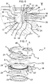
- die Spannvorrichtung gemäß
Figur 4 in einem Querschnitt entlang der Schnittlinie V - V; - Figur 6
- eine Detailansicht der Einzelheit Y der Spannvorrichtung gemäß
Figur 4 ; - Figur 7
- eine erfindungsgemäße Spannvorrichtung in einer zweiten Ausführungsform in perspektivischer Explosionsdarstellung;
- Figur 8
- die Spannvorrichtung gemäß
Figur 7 in einer Draufsicht; - Figur 9
- die Spannvorrichtung gemäß
Figur 8 in einem Längsschnitt entlang der Schnittlinie IX - IX; - Figur 10
- die Spannvorrichtung gemäß
Figur 9 in einem Querschnitt entsprechend der Schnittlinie X - X; und - Figur 11
- eine Detailansicht der Einzelheit Z der Spannvorrichtung gemäß
Figur 9 . -
Figur 1 zeigt schematisch eine erfindungsgemäße Spannvorrichtung 2 für einen Zugmitteltrieb in der Ausgestaltung eines Riementriebes im montierten Zustand an einem Aggregat 30. Dabei bilden die Spannvorrichtung 2 und das Aggregat 30 eine Aggregatanordnung 35. Das Aggregat 30 ist in der dargestellten Form als Lichtmaschine ausgeführt, die ein Gehäuse 31 aufweist, das an einem nicht dargestellten Motorblock befestigt werden kann. Es versteht sich jedoch, dass das Aggregat 30 auch jede andere Arbeitsmaschine sein kann, die Teil des Zugmitteltriebes ist, beispielsweise eine Pumpe. Die Spannvorrichtung 2 ist stirnseitig an dem Gehäuse 31 des Aggregats 30 befestigt. Eine Riemenscheibe 32 ist erkennbar, die über eine Schraubverbindung mit einer Antriebswelle 34 des Aggregats 30 fest verbunden ist. Ein Riemen 33 umschlingt die Riemenscheibe 32 und eine Spannrolle 6, die drehbar auf einem Spannarm 4 gelagert ist. Der Riemen 33 wird durch die Spannrolle 6 vorgespannt. - Die
Figuren 2 bis 6 , welche im Folgenden gemeinsam beschrieben werden, zeigen eine erfindungsgemäße Spannvorrichtung 2 in einer ersten Ausführungsform. Die Spannvorrichtung umfasst einen Grundkörper 3, der mit dem Gehäuse 31 des Aggregats 30 verbunden werden kann, einen Spannarm 4, der um eine Schwenkachse A relativ zum Grundkörper 3 schwenkbar gelagert und über Federmittel 5 an dem Grundkörper 3 federnd abgestützt ist. Die Federmittel 5 sind vorliegend als Schraubenfeder gestaltet, wobei es sich versteht, dass auch beliebige andere Federelemente verwendbar sind, wie eine Spiralfeder oder Bügelfeder. Die schwenkbare Lagerung des Spannarms 4 erfolgt mittels eines ersten Axiallagers 7, das den Spannarm 4 in eine erste axiale Richtung abstützt, eines zweiten Axiallagers 8, das den Spannarm 4 in eine zweite axiale Richtung abstützt und eines Radiallagers 9. Das erste Axiallager 7, das zweite Axiallager 8 und das Radiallager 9 sind in der dargestellten Ausführungsform als einteilige Lagereinheit 16 ausgeführt und an einen Trägerabschnitt 41 des Spannarms 4 angespritzt. Zum Schutz der Lagereinheit 16 vor Umwelteinflüssen sind hierzu radial außenliegend auf dem Trägerabschnitt 41 ein erstes Dichtungselement 10 und ein zweites Dichtungselement 11 angeordnet. Das erste und das zweite Dichtungselement 10 ,11 sind ebenfalls direkt an den Spannarm 4 angespritzt. Auf dem Spannarm 4 ist die Spannrolle 6 drehbar um eine Drehachse B gelagert, die parallel zur Schwenkachse A ist. - Der Grundkörper 3 umfasst drei radial nach außen vorstehende Anschlussflansche 24 mit Bohrungen, durch die Verbindungselemente zur Befestigung an dem Aggregat 30 durchgeführt werden können, einen Aufnahmeabschnitt 36 und eine Axialscheibe 23. Die Axialscheibe 23 ist fest mit dem Aufnahmeabschnitt 36 verbunden. Dies erfolgt durch das Umbördeln eines Hülsenansatzes 37 des Aufnahmeabschnitts 36 nach der Montage des Federelements 5, des Spannarms 4 mit der hiermit verbundenen Lagereinheit 16 und der Dichtungselemente 10, 11, und der Axialscheibe 23. Es sind auch Ausführungen denkbar, bei denen die Axialscheibe über eine Verschraubung oder durch einen Presssitz mit dem Aufnahmeabschnitt 36 verbunden ist. In der dargestellten Ausführungsform weist der Grundkörper 3 an der Axialscheibe 23 eine erste Stützfläche 12 und an dem Aufnahmeabschnitt 36 eine zweite Stützfläche 13 sowie eine Radialanlagefläche 14 auf, die zusammen einen umlaufenden, weitgehenden C-förmigen Querschnitt bilden und durch den ein nach außen offener, kreisringförmiger Bauraum teilweise begrenzt wird, in dem der Spannarm 4 angeordnet ist.
- Das Federelement 5 stützt sich mit einem Federende 25 auf der Seite des Spannarms 4 an einer Anlageschulter 40 und mit einem anderen Federende 25' auf der Seite des Grundkörpers 3 an einer Anlageschulter 40' ab. Durch Schwenken des Spannarms 4 relativ zum Grundkörper 3 wird das Federelement 5 vorgespannt. Das Federelement 5 beaufschlagt damit den Spannarm 4 mit einem die Schwenkbewegung rückstellendem Drehmoment. Die Spannvorrichtung 2 wird in einem Riementrieb in einem verschwenkten Zustand montiert, sodass das rückstellende Drehmoment als Vorspannkraft auf den Riemen 33 einwirkt.
- Das erste Axiallager 7 ist zwischen einer ersten Stützfläche 12' des Spannarms 4 und der ersten Stützfläche 12 des Grundkörpers 3 angeordnet. Das zweite Axiallager 8 ist zwischen einer zweiten Stützfläche 13' des Spannarms 4 und der zweiten Stützfläche 13 des Grundkörpers 3 angeordnet. Das Radiallager 9 ist zwischen einer Radialanlagefläche 14' des Spannarms 4 und einer Radialanlagefläche 14 des Grundkörpers 3 angeordnet. Die erste Stützfläche 12', die zweite Stützfläche 13' sowie die Radialanlagefläche 14' werden dabei teilweise von Ausnehmungen 26 unterbrochen, die zum Zweck der Materialeinsparung vorgesehen werden können. In der dargestellten Ausführung liegen die erste Stützfläche 12' und die zweite Stützfläche 13' jeweils in genau einer Ebene. Es ist auch vorstellbar, dass die beiden Flächen sich jeweils aus Teilbereichen zusammensetzen, die sich in verschiedenen parallelen Ebenen befinden und insbesondere durch Absätze voneinander getrennt sind.
- Das erste Dichtungselement 10 und das zweite Dichtungselement 11 sind radial außenliegend von der Lagereinheit 16 angeordnet und umfassen jeweils einen Profilring 17, 17' und zwei Dichtlippen 18, 18'. Das erste Dichtungselement 10 sitzt mit dem Profilring 17 in einer ersten ringförmigen Nut 19, die in die erste Stützfläche 12' des Spannarms 4 eingearbeitet ist. Das zweite Dichtungselement 11 sitzt mit dem Profilring 17' in einer zweiten ringförmigen Nut 20, die in die zweite Stützfläche 13' des Spannarms 4 eingearbeitet ist. Die Dichtlippen 18 berühren die erste Stützfläche 12, die Dichtlippen 18' die zweite Stützfläche 13 und dichten somit gemeinsam den Raum ab, in dem die Lagereinheit 16 angeordnet ist.
- Die einteilige Lagereinheit 16, bestehend aus einem auf Polyamid basierenden Kunststoff , wird zunächst an den Spannarm 4 angespritzt, wobei das erste Axiallager 7 und das zweite Axiallager 8 über Verbindungshohlzylinder 39 in Bohrungen 15 des Spannarms 4, die in axialer Richtung im Bereich des Trägerabschnitts 41 angeordnet sind, miteinander verbunden sind. Das erste Dichtungselement 10 und das zweite Dichtungselement 11, jeweils bestehend aus einem Thermoplastischen Elastomer, sind in einem weiteren Prozessschritt an bzw. auf das Halbfabrikat aus Spannarm 4 und Lagereinheit 16 gespritzt. Das erste Dichtungselement 10 und das zweite Dichtungselement 11 sind über Verbindungsstege 22 in den Bohrungen 15 des Spannarms 4 miteinander verbunden. In der dargestellten Ausführungsform sind die Verbindungstege 22 durch die Verbindungshohlzylinder 39 geführt. Es ist alternativ auch denkbar, dass die beiden Spritzprozesse so ausgeführt werden, dass in den Bohrungen 15 nur die Verbindungsstege 22 aufgenommen werden. Die dargestellte Ausführungsform umfasst achtzehn Bohrungen 15, die gleichmäßig auf einem Umfang verteilt im Trägerabschnitt 41 des Spannarms 4 angeordnet sind und jeweils einen Verbindungshohlzylinder 39 und einen Verbindungssteg 22 aufnehmen. Es versteht sich, dass auch eine hiervon abweichende Zahl von Verbindungsstegen 22 verwendet werden kann.
- Eine zusätzliche dem ersten Dichtungselement 10 und dem zweiten Dichtungselement 11 vorgelagerte Abdichtung der Lagereinheit 16 wird über eine seitliche Abdeckung durch einen Ringspalt 29 erzielt. Der Ringspalt 29 wird durch einen ersten Versatz 27 der Axialscheibe 23 und einen zweiten Versatz 28 des Spannarms 4 gebildet und wirkt als Filter für grobe Schmutzpartikel und schützt vor allem die Dichtungselement 10, 11 vor Beschädigungen. Des Weiteren wirkt der Ringspalt 29 nach Art einer Labyrinthdichtung, die das Eintreten von Fluiden, beispielsweise Spritzwasser, in den Bauraum, in dem Dichtungselemente 10, 11 und die Lagereinheit 16 angeordnet sind, einschränken kann.
- Als Schutz des Federelements 5 vor Verschleiß auf Grund von Relativbewegungen gegenüber dem Grundkörper 3 und dem Spannarm 4 sind in den Kontaktbereichen an Grundkörper 3 und dem Spannarm 4 Verschleißschutzelemente 21 angeordnet. Die Verschleißschutzelemente 21 sind als Kunststoffeinsätze ausgeführt, die bei fortschreitendem Verschleiß getauscht werden können. Die Verschleißschutzelemente 21 sind insbesondere aus dem gleichen Material wie die Lagereinheit 16 hergestellt.
- Die
Figuren 7 bis 11 , welche im Folgenden gemeinsam beschrieben werden, zeigen eine erfindungsgemäße Spannvorrichtung 2 in einer zweiten Ausführungsform. Die Spannvorrichtung umfasst einen Grundkörper 3, der über drei Anschlussflansche 24 mittels Befestigungsmitteln mit dem Gehäuse 31 des Aggregats 30 verbunden werden kann, einen Spannarm 4, der um eine Schwenkachse A relativ zum Grundkörper 3 schwenkbar gelagert und über Federmittel 5 an dem Grundkörper 3 federnd abgestützt ist. Die Federmittel 5 sind auch hier als Schraubenfeder ausgeführt, ohne hierauf eingeschränkt zu sein. Die schwenkbare Lagerung des Spannarms 4 erfolgt mittels eines ersten Axiallagers 7, das den Spannarm 4 in eine erste axiale Richtung abstützt, eines zweiten Axiallagers 8, das den Spannarm 4 in eine zweite axiale Richtung abstützt und eines Radiallagers 9. In der dargestellten Ausführungsform sind das erste Axiallager 7 und das Radiallager 9 als einteilige Lagereinheit 16 ausgeführt, der an einem Trägerabschnitt 41 des Grundkörpers 3 angespritzt ist. Das zweite Axiallager 8 ist eine separate Anlaufscheibe. Zum Schutz der Lagereinheit 16 und des zweiten Axiallagers 8 vor Umwelteinflüssen sind radial außenliegend auf dem Trägerabschnitt 41 ein erstes Dichtungselement 10 und ein zweites Dichtungselement 11 angeordnet. Die Dichtungselemente 10, 11 sind direkt an den Grundkörper 3 angespritzt. - Der Spannarm 4 weist eine Spannrolle 6, die drehbar um eine zur Schwenkachse A parallele Drehachse B gelagert ist, einen Aufnahmeabschnitt 36 und eine Axialscheibe 23 auf. Die Axialscheibe 23 ist fest mit dem Aufnahmeabschnitt 36 verbunden. Dies erfolgt durch das Umbördeln eines Hülsenansatzes 37 des Aufnahmeabschnitts 36 nach der Montage des Federelements 5, des Grundkörpers 4 mit der hiermit verbundenen Lagereinheit 16 und den Dichtungselementen 10, 11, dem zweiten Axiallager 8 und der Axialscheibe 23. In der dargestellten Ausführungsform weist der Spannarm 4 an dem Aufnahmeabschnitt 36 eine erste Stützfläche 12 sowie eine Radialanlagefläche 14 und an der Axialscheibe 23 eine zweite Stützfläche 13 auf, die zusammen einen in umlaufenden, weitgehenden C-förmigen Querschnitt bilden und durch den ein nach außen offener, kreisringförmigen Bauraum teilweise begrenzt wird, in dem der Grundkörper 3 angeordnet ist.
- Das Federelement 5 stützt sich mit einem Federende 25 auf der Seite des Spannarms 4 an einer Anlageschulter 40 und mit einem anderen Federende 25' auf der Seite des Grundkörpers 3 an einer Anlageschulter 40' ab. Durch Schwenken des Spannarms 4 relativ zum Grundkörper 3 wird das Federelement 5 vorgespannt. Das Federelement 5 beaufschlagt damit den Spannarm 4 mit einem die Schwenkbewegung rückstellendem Drehmoment. Die Spannvorrichtung 2 wird in einem Riementrieb in einem verschwenkten Zustand montiert, sodass das rückstellende Drehmoment als Vorspannkraft auf den Riemen 33 einwirkt.
- Das erste Axiallager 7 ist zwischen der ersten Stützfläche 12 des Spannarms 4 und einer ersten Stützfläche 12' des Grundkörpers 3 angeordnet. Das zweite Axiallager 8 ist zwischen der zweiten Stützfläche 13 des Spannarms 4 und einer zweiten Stützfläche 13' des Grundkörpers 3 angeordnet. Das Radiallager 9 ist zwischen der Radialanlagefläche 14 des Spannarms 4 und einer Radialanlagefläche 14' des Grundkörpers 3 angeordnet.
- Das erste Dichtungselement 10 und das zweite Dichtungselement 11 sind radial außenliegend von der Lagereinheit 16 und von dem zweiten Axiallager 8 angeordnet und umfassen jeweils einen Profilring 17, 17' und zwei Dichtlippen 18, 18'. Das erste Dichtungselement 10 sitzt mit dem Profilring 17 in einer ersten ringförmigen Nut 19, die in die erste Stützfläche 12' des Grundkörpers 3 eingearbeitet ist. Das zweite Dichtungselement 11 sitzt mit dem Profilring 17' in einer zweiten ringförmigen Nut 20, die in die zweite Stützfläche 13' des Grundkörpers 3 eingearbeitet ist. Die Dichtlippen 18 berühren die erste Stützfläche 12 des Spannarms 4, die Dichtlippen 18' berühren die zweite Stützfläche 13 des Spannarms 4 und dichten somit gemeinsam den Raum ab, in dem die Lagereinheit 16 und das zweite Axiallager 8 angeordnet sind.
- Das erste Dichtungselement 10 und das zweite Dichtungselement 11 sind in einem Prozessschritt an bzw. auf das Halbfabrikat aus Grundkörper 3 und Lagereinheit 16 gespritzt. Das erste Dichtungselement 10 und das zweite Dichtungselement 11 sind über Verbindungsstege 22 in den Bohrungen 15 des Grundkörpers 3 miteinander verbunden. Die dargestellte Ausführungsform umfasst achtzehn Bohrungen 15, die gleichmäßig auf einem Umfang verteilt im Trägerabschnitt 41 des Grundkörpers 3 angeordnet sind. Es versteht sich, dass auch eine hiervon abweichende Zahl an Verbindungsstegen 22 verwendet werden kann.
- Als Schutz des Federelements 5 vor Verschleiß auf Grund von Relativbewegungen gegenüber dem Grundkörper 3 und dem Spannarm 4 sind in den Kontaktbereichen an Grundkörper 3 und dem Spannarm 4 Verschleißschutzelemente 21 angeordnet. Die Verschleißschutzelemente 21 sind als Kunststoffeinsätze ausgeführt, die bei fortschreitendem Verschleiß getauscht werden können.
-
- 2
- Spannvorrichtung
- 3
- Grundkörper
- 4
- Spannarm
- 5
- Federmittel
- 6
- Spannrolle
- 7
- Erstes Axiallager
- 8
- Zweites Axiallager
- 9
- Radiallager
- 10
- Erstes Dichtungselement
- 11
- Zweites Dichtungselement
- 12, 12'
- Erste Stützfläche
- 13, 13'
- Zweite Stützfläche
- 14, 14'
- Radialanlagefläche
- 15
- Bohrung
- 16
- Lagereinheit
- 17, 17'
- Profilring
- 18, 18'
- Dichtlippe
- 19
- Erste Nut
- 20
- Zweite Nut
- 21
- Verschleißschutzelement
- 22
- Verbindungssteg
- 23
- Axialscheibe
- 24
- Anschlussflansch
- 25, 25'
- Federenden
- 26
- Ausnehmungen
- 27
- Erster Versatz
- 28
- Zweiter Versatz
- 29
- Ringspalt
- 30
- Aggregat
- 31
- Gehäuse
- 32
- Riemenscheibe
- 33
- Riemen/ Zugmittel
- 34
- Antriebswelle
- 35
- Aggregatanordnung
- 36
- Aufnahmeabschnitt
- 37
- Hülsenansatz
- 38
- 39
- Verbindungshohlzylinder
- 40, 40'
- Anlageschulter
- 41
- Trägerabschnitt
- A
- Schwenkachse
- B
- Drehachse
Claims (14)
- Spannvorrichtung (2) für einen Zugmitteltrieb, umfassend:einen Grundkörper (3),einen Spannarm (4), der mittels eines Radiallagers (9) relativ zum Grundkörper (3) um eine Schwenkachse (A) schwenkbar gelagert ist,wobei eines von den Teilen Grundkörper und Spannarm (3, 4) einen ringförmigen Trägerabschnitt (41) aufweist, der gegenüber dem anderen der beiden Teile Spannarm und Grundkörper (4, 3) mittels eines ersten Axiallagers (7) in eine erste Richtung und mittels eines zweiten Axiallagers (8) in eine zweite Richtung axial abgestützt ist,eine erstes Dichtungselement (10), das mit dem Trägerabschnitt (41) zum Abdichten des ersten Axiallagers (7) verbunden ist,eine zweites Dichtungselement (11), das mit dem Trägerabschnitt (41) zum Abdichten des zweiten Axiallagers (8) verbunden ist,wobei das erste und das zweite Axiallager (7, 8) aus einem anderen Material hergestellt sind, als das erste und das zweite Dichtungselement (10, 11),eine Spannrolle (6), die an dem Spannarm (4) drehbar gelagert ist und zum Spannen des Zugmittels (33) dient,dadurch gekennzeichnet, dass die Spannvorrichtung weiterhin Federmittel (5), über die der Spannarm (4) in Umfangsrichtung gegen den Grundkörper (3) abgestützt ist, umfasst unddass das erste Dichtungselement (10) und das zweite Dichtungselement (11) mittels mehrerer Verbindungsstege (22), die sich durch Bohrungen (15) des Trägerabschnitts (41) hindurcherstrecken, miteinander verbunden sind.
- Spannvorrichtung nach Anspruch 1,
dadurch gekennzeichnet,
dass das erste und das zweite Dichtungselement (10, 11) aus einem Material aus der Gruppe Thermoplastischer Elastomere, insbesondere der Thermoplastischen Elastomere auf Urethanbasis, oder aus einem vulkanisierten Kautschukwerkstoff hergestellt sind. - Spannvorrichtung nach Anspruch 1 oder 2,
dadurch gekennzeichnet,
dass das erste und das zweite Axiallager (7, 8) aus einem auf Polyamid oder Polyoxymethylen basierenden Kunststoff hergestellt sind. - Spannvorrichtung nach einem der Ansprüche 1 bis 3,
dadurch gekennzeichnet,
dass das erste Dichtungselement (10) mit dem ersten Axiallager (7) und das zweite Dichtungselement (11) mit dem zweiten Axiallager (8) jeweils formschlüssig verbunden sind. - Spannvorrichtung nach Anspruch 4,
dadurch gekennzeichnet,
dass das erste Dichtungselement (10) und das erste Axiallager (7) sowie das zweite Dichtungselement (11) und das zweite Axiallager (8) jeweils eine gegenseitig komplementäre Eingriffsstruktur aufweisen. - Spannvorrichtung nach einem der Ansprüche 1 bis 5,
dadurch gekennzeichnet,
dass zumindest eines von dem ersten Axiallager (7) und dem zweiten Axiallager (8) einteilig mit dem Radiallager (9) ausgeführt ist und eine Lagereinheit (16) bildet. - Spannvorrichtung nach Anspruch 6,
dadurch gekennzeichnet,
dass die Lagereinheit (16) mit dem Grundkörper (3) oder Spannarm (4) verbunden ist, insbesondere die Lagereinheit (16) an den Grundkörper (3) oder den Spannarm (4) angespritzt ist. - Spannvorrichtung nach einem der Ansprüche 1 bis 7,
dadurch gekennzeichnet,
dass das erste Dichtungselement (10) und das zweite Dichtungselement (11) jeweils einen geschlossenen Profilring (17, 17') und zumindest eine Dichtlippe (18, 18') umfassen. - Spannvorrichtung nach Anspruch 8,
dadurch gekennzeichnet,
dass der Profilring (17) des ersten Dichtungselements (10) mit dem Spannarm (4) verbunden ist und die zumindest eine Dichtlippe (18) des ersten Dichtungselements (10) am Grundkörper (3) anliegt und
dass der Profilring (17') des zweiten Dichtungselements (11) mit dem Spannarm (4) verbunden ist und die zumindest eine Dichtlippe (18') des zweiten Dichtungselements (11) am Grundkörper (3) anliegt. (Figuren 2 bis 6) - Spannvorrichtung nach Anspruch 8,
dadurch gekennzeichnet,
dass der Profilring (17) des ersten Dichtungselements (10) mit dem Grundkörper (3) verbunden ist und die zumindest eine Dichtlippe (18) des ersten Dichtungselements (10) am Spannarm (4) anliegt und
dass der Profilring (17') des zweiten Dichtungselements (11) mit dem Grundkörper (3) verbunden ist und die zumindest eine Dichtlippe (18') des zweiten Dichtungselements (11) am Spannarm (4) anliegt. (Figuren 7 bis 11) - Spannvorrichtung nach einem der Ansprüche 1 bis 10,
dadurch gekennzeichnet,
dass das erste Dichtungselement (10) in einer ringförmigen ersten Nut (19) und das zweite Dichtungselements (11) in einer ringförmigen zweiten Nut (20) angeordnet sind, wobei die erste Nut (19) und die zweite Nut (20) in entgegengesetzten Stützflächen (12',13') des Trägerabschnitts (41) vorgesehen sind. - Spannvorrichtung nach einem der Ansprüche 1 bis 11,
dadurch gekennzeichnet,
dass der Grundkörper (3) einen ersten Versatz (27) und der Spannarm (4) einen zweiten Versatz (28) aufweist,
wobei der erste Versatz (27) und der zweite Versatz (28) bezogen auf die Schwenkachse (A) radial außen vom ersten Dichtungselement (10) angeordnet und gleichgerichtet sind, sodass zwischen dem Grundkörper (3) und dem Spannarm (4) ein S-förmiger Ringspalt (29) gebildet ist. - Spannvorrichtung nach einem der Ansprüche 1 bis 12,
dadurch gekennzeichnet,
dass zumindest eines von dem Grundkörper (3) und dem Spannarm (4) in einem Bereich, in dem die Federmittel (5) anliegen, zumindest ein Verschleißschutzelement (21) aufweist, das insbesondere aus einem Kunststoff hergestellt ist. - Spannvorrichtung nach einem der Ansprüche 1 bis 13,
dadurch gekennzeichnet,
dass die Anzahl der Bohrungen (15) im Trägerabschnitt (41) größer 6, insbesondere größer 12, und/oder kleiner 24, insbesondere kleiner 18, ist.
Priority Applications (1)
| Application Number | Priority Date | Filing Date | Title |
|---|---|---|---|
| PL18205209T PL3492777T3 (pl) | 2017-11-29 | 2018-11-08 | Urządzenie napinające do przekładni cięgnowej |
Applications Claiming Priority (1)
| Application Number | Priority Date | Filing Date | Title |
|---|---|---|---|
| DE102017128280.7A DE102017128280A1 (de) | 2017-11-29 | 2017-11-29 | Spannvorrichtung für einen zugmitteltrieb |
Publications (2)
| Publication Number | Publication Date |
|---|---|
| EP3492777A1 EP3492777A1 (de) | 2019-06-05 |
| EP3492777B1 true EP3492777B1 (de) | 2020-12-09 |
Family
ID=64267681
Family Applications (1)
| Application Number | Title | Priority Date | Filing Date |
|---|---|---|---|
| EP18205209.2A Active EP3492777B1 (de) | 2017-11-29 | 2018-11-08 | Spannvorrichtung für einen zugmitteltrieb |
Country Status (8)
| Country | Link |
|---|---|
| US (1) | US20190162276A1 (de) |
| EP (1) | EP3492777B1 (de) |
| JP (1) | JP2019100546A (de) |
| KR (1) | KR20190063416A (de) |
| CN (1) | CN109838522B (de) |
| DE (1) | DE102017128280A1 (de) |
| ES (1) | ES2860980T3 (de) |
| PL (1) | PL3492777T3 (de) |
Families Citing this family (3)
| Publication number | Priority date | Publication date | Assignee | Title |
|---|---|---|---|---|
| DE102016217933B4 (de) * | 2016-09-20 | 2020-06-04 | Schaeffler Technologies AG & Co. KG | Riemenspanner |
| DE102020129439A1 (de) | 2020-07-09 | 2022-01-13 | Schaeffler Technologies AG & Co. KG | Riemenspanner |
| DE102020004335A1 (de) * | 2020-07-20 | 2022-01-20 | Muhr Und Bender Kg | Riemenspannvorrichtung und Riementrieb mit einer solchen Riemenspannvorrichtung |
Family Cites Families (8)
| Publication number | Priority date | Publication date | Assignee | Title |
|---|---|---|---|---|
| DE102005029936B4 (de) * | 2005-06-28 | 2016-01-07 | Schaeffler Technologies AG & Co. KG | Abgedichtetes Wälzlager |
| DE102006047095B4 (de) * | 2006-10-05 | 2021-05-12 | Schaeffler Technologies AG & Co. KG | Spannvorrichtung |
| DE102008011786A1 (de) * | 2008-02-28 | 2009-09-03 | Schaeffler Kg | Reib- und Dämpfungselement mit integrierter Dichtlippe |
| DE102010019054A1 (de) * | 2010-05-03 | 2011-11-03 | Schaeffler Technologies Gmbh & Co. Kg | Spannvorrichtung |
| DE102011053869B4 (de) | 2011-09-22 | 2020-03-26 | Muhr Und Bender Kg | Riemenspannvorrichtung für einen Riementrieb und Aggregatanordnung mit Riemenspannvorrichtung |
| WO2014090417A1 (de) | 2012-12-13 | 2014-06-19 | Schaeffler Technologies AG & Co. KG | Riemenspanner |
| DE102013203522A1 (de) * | 2013-03-01 | 2014-09-04 | Schaeffler Technologies Gmbh & Co. Kg | Riemenspanner |
| DE102014117094A1 (de) * | 2014-11-21 | 2016-05-25 | Muhr Und Bender Kg | Riemenspannvorrichtung |
-
2017
- 2017-11-29 DE DE102017128280.7A patent/DE102017128280A1/de not_active Withdrawn
-
2018
- 2018-11-07 US US16/182,698 patent/US20190162276A1/en not_active Abandoned
- 2018-11-08 PL PL18205209T patent/PL3492777T3/pl unknown
- 2018-11-08 EP EP18205209.2A patent/EP3492777B1/de active Active
- 2018-11-08 ES ES18205209T patent/ES2860980T3/es active Active
- 2018-11-26 KR KR1020180147039A patent/KR20190063416A/ko not_active Withdrawn
- 2018-11-27 JP JP2018221437A patent/JP2019100546A/ja active Pending
- 2018-11-28 CN CN201811433900.XA patent/CN109838522B/zh active Active
Non-Patent Citations (1)
| Title |
|---|
| None * |
Also Published As
| Publication number | Publication date |
|---|---|
| US20190162276A1 (en) | 2019-05-30 |
| DE102017128280A1 (de) | 2019-05-29 |
| CN109838522A (zh) | 2019-06-04 |
| EP3492777A1 (de) | 2019-06-05 |
| KR20190063416A (ko) | 2019-06-07 |
| CN109838522B (zh) | 2024-01-02 |
| ES2860980T3 (es) | 2021-10-05 |
| JP2019100546A (ja) | 2019-06-24 |
| PL3492777T3 (pl) | 2021-05-17 |
Similar Documents
| Publication | Publication Date | Title |
|---|---|---|
| EP3023670B1 (de) | Riemenspannvorrichtung | |
| EP3492777B1 (de) | Spannvorrichtung für einen zugmitteltrieb | |
| EP3374666B1 (de) | Spielfreie pendellagerung am entkopplungsspanner | |
| DE102013102562A1 (de) | Feder, Riemenspannvorrichtung und Aggregatanordnung | |
| EP3885609B1 (de) | Riemenspannvorrichtung | |
| EP3431815A1 (de) | Riemenspannvorrichtung | |
| DE10311938A1 (de) | Laufrad für Fahrzeuge der Raupenbauweise mit reduzierter Lärmübertragung | |
| DE602004001084T2 (de) | Kreuzgelenk mit entlüftender Dichtung | |
| WO2005019696A1 (de) | Abdichtung für ein wälzlager | |
| DE102016214261A1 (de) | Verfahren zur Herstellung einer Riemenscheibenvorrichtung, Riemenscheibenvorrichtung gemäß einem solchen Herstellungsverfahren und mit einer solchen Riemenscheibe ausgestatteter Motor | |
| DE102015215421A1 (de) | Ringspanner mit gleichteiliger Ringhebellagerung | |
| DE60320424T2 (de) | Run-flat-vorrichtung | |
| DE202008011734U1 (de) | Riemenspanneinrichtung | |
| DE2403111A1 (de) | Gelenkverbindung | |
| DE102007037214A1 (de) | Wellendichtringsystem | |
| EP3880986B1 (de) | Ausgleichswelle | |
| DE102007057306A1 (de) | Radlager-Wälzlagereinheit mit Dichtring | |
| DE102018113626A1 (de) | Dämpferriemenscheibe für eine Kurbelwelle | |
| DE102014209780A1 (de) | Exzenterspanner für einen Zugmitteltrieb eines Verbrennungsmotors | |
| EP3889012A1 (de) | Gummiraupenfahrwerk | |
| DE4340865A1 (de) | Spannvorrichtung für Zugmitteltriebe | |
| DE102008064341A1 (de) | Riemenscheibe mit Freilauf und Torsionsschwingungsdämpfer sowie Riemenstarter für eine Brennkraftmaschine | |
| DE2834979A1 (de) | Waelzgelagerte rolle | |
| DE69407204T2 (de) | Radialwellendichtung mit einem Schutz- und Zentrierelement | |
| DE4336467A1 (de) | Riemenspanneinrichtung mit einem gegenüber einem Reibelement abgedichteten Radiallager |
Legal Events
| Date | Code | Title | Description |
|---|---|---|---|
| PUAI | Public reference made under article 153(3) epc to a published international application that has entered the european phase |
Free format text: ORIGINAL CODE: 0009012 |
|
| STAA | Information on the status of an ep patent application or granted ep patent |
Free format text: STATUS: THE APPLICATION HAS BEEN PUBLISHED |
|
| AK | Designated contracting states |
Kind code of ref document: A1 Designated state(s): AL AT BE BG CH CY CZ DE DK EE ES FI FR GB GR HR HU IE IS IT LI LT LU LV MC MK MT NL NO PL PT RO RS SE SI SK SM TR |
|
| AX | Request for extension of the european patent |
Extension state: BA ME |
|
| STAA | Information on the status of an ep patent application or granted ep patent |
Free format text: STATUS: REQUEST FOR EXAMINATION WAS MADE |
|
| 17P | Request for examination filed |
Effective date: 20191108 |
|
| RBV | Designated contracting states (corrected) |
Designated state(s): AL AT BE BG CH CY CZ DE DK EE ES FI FR GB GR HR HU IE IS IT LI LT LU LV MC MK MT NL NO PL PT RO RS SE SI SK SM TR |
|
| GRAP | Despatch of communication of intention to grant a patent |
Free format text: ORIGINAL CODE: EPIDOSNIGR1 |
|
| STAA | Information on the status of an ep patent application or granted ep patent |
Free format text: STATUS: GRANT OF PATENT IS INTENDED |
|
| RIC1 | Information provided on ipc code assigned before grant |
Ipc: F16H 7/12 20060101AFI20200512BHEP |
|
| INTG | Intention to grant announced |
Effective date: 20200615 |
|
| GRAS | Grant fee paid |
Free format text: ORIGINAL CODE: EPIDOSNIGR3 |
|
| GRAA | (expected) grant |
Free format text: ORIGINAL CODE: 0009210 |
|
| STAA | Information on the status of an ep patent application or granted ep patent |
Free format text: STATUS: THE PATENT HAS BEEN GRANTED |
|
| AK | Designated contracting states |
Kind code of ref document: B1 Designated state(s): AL AT BE BG CH CY CZ DE DK EE ES FI FR GB GR HR HU IE IS IT LI LT LU LV MC MK MT NL NO PL PT RO RS SE SI SK SM TR |
|
| REG | Reference to a national code |
Ref country code: GB Ref legal event code: FG4D Free format text: NOT ENGLISH |
|
| REG | Reference to a national code |
Ref country code: AT Ref legal event code: REF Ref document number: 1343779 Country of ref document: AT Kind code of ref document: T Effective date: 20201215 Ref country code: CH Ref legal event code: EP |
|
| REG | Reference to a national code |
Ref country code: DE Ref legal event code: R096 Ref document number: 502018003257 Country of ref document: DE |
|
| REG | Reference to a national code |
Ref country code: IE Ref legal event code: FG4D Free format text: LANGUAGE OF EP DOCUMENT: GERMAN |
|
| REG | Reference to a national code |
Ref country code: SK Ref legal event code: T3 Ref document number: E 36430 Country of ref document: SK |
|
| PG25 | Lapsed in a contracting state [announced via postgrant information from national office to epo] |
Ref country code: FI Free format text: LAPSE BECAUSE OF FAILURE TO SUBMIT A TRANSLATION OF THE DESCRIPTION OR TO PAY THE FEE WITHIN THE PRESCRIBED TIME-LIMIT Effective date: 20201209 Ref country code: RS Free format text: LAPSE BECAUSE OF FAILURE TO SUBMIT A TRANSLATION OF THE DESCRIPTION OR TO PAY THE FEE WITHIN THE PRESCRIBED TIME-LIMIT Effective date: 20201209 Ref country code: NO Free format text: LAPSE BECAUSE OF FAILURE TO SUBMIT A TRANSLATION OF THE DESCRIPTION OR TO PAY THE FEE WITHIN THE PRESCRIBED TIME-LIMIT Effective date: 20210309 Ref country code: GR Free format text: LAPSE BECAUSE OF FAILURE TO SUBMIT A TRANSLATION OF THE DESCRIPTION OR TO PAY THE FEE WITHIN THE PRESCRIBED TIME-LIMIT Effective date: 20210310 |
|
| PG25 | Lapsed in a contracting state [announced via postgrant information from national office to epo] |
Ref country code: BG Free format text: LAPSE BECAUSE OF FAILURE TO SUBMIT A TRANSLATION OF THE DESCRIPTION OR TO PAY THE FEE WITHIN THE PRESCRIBED TIME-LIMIT Effective date: 20210309 Ref country code: LV Free format text: LAPSE BECAUSE OF FAILURE TO SUBMIT A TRANSLATION OF THE DESCRIPTION OR TO PAY THE FEE WITHIN THE PRESCRIBED TIME-LIMIT Effective date: 20201209 Ref country code: SE Free format text: LAPSE BECAUSE OF FAILURE TO SUBMIT A TRANSLATION OF THE DESCRIPTION OR TO PAY THE FEE WITHIN THE PRESCRIBED TIME-LIMIT Effective date: 20201209 |
|
| REG | Reference to a national code |
Ref country code: NL Ref legal event code: MP Effective date: 20201209 |
|
| PG25 | Lapsed in a contracting state [announced via postgrant information from national office to epo] |
Ref country code: NL Free format text: LAPSE BECAUSE OF FAILURE TO SUBMIT A TRANSLATION OF THE DESCRIPTION OR TO PAY THE FEE WITHIN THE PRESCRIBED TIME-LIMIT Effective date: 20201209 Ref country code: HR Free format text: LAPSE BECAUSE OF FAILURE TO SUBMIT A TRANSLATION OF THE DESCRIPTION OR TO PAY THE FEE WITHIN THE PRESCRIBED TIME-LIMIT Effective date: 20201209 |
|
| REG | Reference to a national code |
Ref country code: LT Ref legal event code: MG9D |
|
| PG25 | Lapsed in a contracting state [announced via postgrant information from national office to epo] |
Ref country code: LT Free format text: LAPSE BECAUSE OF FAILURE TO SUBMIT A TRANSLATION OF THE DESCRIPTION OR TO PAY THE FEE WITHIN THE PRESCRIBED TIME-LIMIT Effective date: 20201209 Ref country code: PT Free format text: LAPSE BECAUSE OF FAILURE TO SUBMIT A TRANSLATION OF THE DESCRIPTION OR TO PAY THE FEE WITHIN THE PRESCRIBED TIME-LIMIT Effective date: 20210409 Ref country code: RO Free format text: LAPSE BECAUSE OF FAILURE TO SUBMIT A TRANSLATION OF THE DESCRIPTION OR TO PAY THE FEE WITHIN THE PRESCRIBED TIME-LIMIT Effective date: 20201209 Ref country code: SM Free format text: LAPSE BECAUSE OF FAILURE TO SUBMIT A TRANSLATION OF THE DESCRIPTION OR TO PAY THE FEE WITHIN THE PRESCRIBED TIME-LIMIT Effective date: 20201209 Ref country code: EE Free format text: LAPSE BECAUSE OF FAILURE TO SUBMIT A TRANSLATION OF THE DESCRIPTION OR TO PAY THE FEE WITHIN THE PRESCRIBED TIME-LIMIT Effective date: 20201209 |
|
| REG | Reference to a national code |
Ref country code: DE Ref legal event code: R097 Ref document number: 502018003257 Country of ref document: DE |
|
| PG25 | Lapsed in a contracting state [announced via postgrant information from national office to epo] |
Ref country code: IS Free format text: LAPSE BECAUSE OF FAILURE TO SUBMIT A TRANSLATION OF THE DESCRIPTION OR TO PAY THE FEE WITHIN THE PRESCRIBED TIME-LIMIT Effective date: 20210409 |
|
| PLBE | No opposition filed within time limit |
Free format text: ORIGINAL CODE: 0009261 |
|
| STAA | Information on the status of an ep patent application or granted ep patent |
Free format text: STATUS: NO OPPOSITION FILED WITHIN TIME LIMIT |
|
| PG25 | Lapsed in a contracting state [announced via postgrant information from national office to epo] |
Ref country code: AL Free format text: LAPSE BECAUSE OF FAILURE TO SUBMIT A TRANSLATION OF THE DESCRIPTION OR TO PAY THE FEE WITHIN THE PRESCRIBED TIME-LIMIT Effective date: 20201209 |
|
| 26N | No opposition filed |
Effective date: 20210910 |
|
| PG25 | Lapsed in a contracting state [announced via postgrant information from national office to epo] |
Ref country code: DK Free format text: LAPSE BECAUSE OF FAILURE TO SUBMIT A TRANSLATION OF THE DESCRIPTION OR TO PAY THE FEE WITHIN THE PRESCRIBED TIME-LIMIT Effective date: 20201209 Ref country code: SI Free format text: LAPSE BECAUSE OF FAILURE TO SUBMIT A TRANSLATION OF THE DESCRIPTION OR TO PAY THE FEE WITHIN THE PRESCRIBED TIME-LIMIT Effective date: 20201209 |
|
| PG25 | Lapsed in a contracting state [announced via postgrant information from national office to epo] |
Ref country code: IS Free format text: LAPSE BECAUSE OF FAILURE TO SUBMIT A TRANSLATION OF THE DESCRIPTION OR TO PAY THE FEE WITHIN THE PRESCRIBED TIME-LIMIT Effective date: 20210409 |
|
| PG25 | Lapsed in a contracting state [announced via postgrant information from national office to epo] |
Ref country code: MC Free format text: LAPSE BECAUSE OF FAILURE TO SUBMIT A TRANSLATION OF THE DESCRIPTION OR TO PAY THE FEE WITHIN THE PRESCRIBED TIME-LIMIT Effective date: 20201209 |
|
| REG | Reference to a national code |
Ref country code: CH Ref legal event code: PL |
|
| PG25 | Lapsed in a contracting state [announced via postgrant information from national office to epo] |
Ref country code: LU Free format text: LAPSE BECAUSE OF NON-PAYMENT OF DUE FEES Effective date: 20211108 Ref country code: BE Free format text: LAPSE BECAUSE OF NON-PAYMENT OF DUE FEES Effective date: 20211130 |
|
| REG | Reference to a national code |
Ref country code: BE Ref legal event code: MM Effective date: 20211130 |
|
| PG25 | Lapsed in a contracting state [announced via postgrant information from national office to epo] |
Ref country code: IE Free format text: LAPSE BECAUSE OF NON-PAYMENT OF DUE FEES Effective date: 20211108 |
|
| PG25 | Lapsed in a contracting state [announced via postgrant information from national office to epo] |
Ref country code: CY Free format text: LAPSE BECAUSE OF FAILURE TO SUBMIT A TRANSLATION OF THE DESCRIPTION OR TO PAY THE FEE WITHIN THE PRESCRIBED TIME-LIMIT Effective date: 20201209 |
|
| GBPC | Gb: european patent ceased through non-payment of renewal fee |
Effective date: 20221108 |
|
| PG25 | Lapsed in a contracting state [announced via postgrant information from national office to epo] |
Ref country code: LI Free format text: LAPSE BECAUSE OF NON-PAYMENT OF DUE FEES Effective date: 20220701 Ref country code: HU Free format text: LAPSE BECAUSE OF FAILURE TO SUBMIT A TRANSLATION OF THE DESCRIPTION OR TO PAY THE FEE WITHIN THE PRESCRIBED TIME-LIMIT; INVALID AB INITIO Effective date: 20181108 Ref country code: CH Free format text: LAPSE BECAUSE OF NON-PAYMENT OF DUE FEES Effective date: 20220701 |
|
| PG25 | Lapsed in a contracting state [announced via postgrant information from national office to epo] |
Ref country code: GB Free format text: LAPSE BECAUSE OF NON-PAYMENT OF DUE FEES Effective date: 20221108 |
|
| PG25 | Lapsed in a contracting state [announced via postgrant information from national office to epo] |
Ref country code: MK Free format text: LAPSE BECAUSE OF FAILURE TO SUBMIT A TRANSLATION OF THE DESCRIPTION OR TO PAY THE FEE WITHIN THE PRESCRIBED TIME-LIMIT Effective date: 20201209 |
|
| PG25 | Lapsed in a contracting state [announced via postgrant information from national office to epo] |
Ref country code: MT Free format text: LAPSE BECAUSE OF FAILURE TO SUBMIT A TRANSLATION OF THE DESCRIPTION OR TO PAY THE FEE WITHIN THE PRESCRIBED TIME-LIMIT Effective date: 20201209 |
|
| REG | Reference to a national code |
Ref country code: AT Ref legal event code: MM01 Ref document number: 1343779 Country of ref document: AT Kind code of ref document: T Effective date: 20231108 |
|
| PG25 | Lapsed in a contracting state [announced via postgrant information from national office to epo] |
Ref country code: AT Free format text: LAPSE BECAUSE OF NON-PAYMENT OF DUE FEES Effective date: 20231108 |
|
| PG25 | Lapsed in a contracting state [announced via postgrant information from national office to epo] |
Ref country code: AT Free format text: LAPSE BECAUSE OF NON-PAYMENT OF DUE FEES Effective date: 20231108 |
|
| PG25 | Lapsed in a contracting state [announced via postgrant information from national office to epo] |
Ref country code: TR Free format text: LAPSE BECAUSE OF FAILURE TO SUBMIT A TRANSLATION OF THE DESCRIPTION OR TO PAY THE FEE WITHIN THE PRESCRIBED TIME-LIMIT Effective date: 20201209 |
|
| PGFP | Annual fee paid to national office [announced via postgrant information from national office to epo] |
Ref country code: DE Payment date: 20251107 Year of fee payment: 8 |
|
| PGFP | Annual fee paid to national office [announced via postgrant information from national office to epo] |
Ref country code: IT Payment date: 20251121 Year of fee payment: 8 |
|
| PGFP | Annual fee paid to national office [announced via postgrant information from national office to epo] |
Ref country code: FR Payment date: 20251126 Year of fee payment: 8 |
|
| PGFP | Annual fee paid to national office [announced via postgrant information from national office to epo] |
Ref country code: CZ Payment date: 20251104 Year of fee payment: 8 |
|
| PGFP | Annual fee paid to national office [announced via postgrant information from national office to epo] |
Ref country code: PL Payment date: 20251110 Year of fee payment: 8 |
|
| PGFP | Annual fee paid to national office [announced via postgrant information from national office to epo] |
Ref country code: SK Payment date: 20251104 Year of fee payment: 8 |
|
| PGFP | Annual fee paid to national office [announced via postgrant information from national office to epo] |
Ref country code: ES Payment date: 20251205 Year of fee payment: 8 |
|
| PGFP | Annual fee paid to national office [announced via postgrant information from national office to epo] |
Ref country code: AT Payment date: 20260410 Year of fee payment: 5 |