EP3492821A2 - Système, dispositif, équipement sanitaire et procédé de surveillance de la prise d'eau à partir d'une pluralité de points de prélèvement sanitaire - Google Patents
Système, dispositif, équipement sanitaire et procédé de surveillance de la prise d'eau à partir d'une pluralité de points de prélèvement sanitaire Download PDFInfo
- Publication number
- EP3492821A2 EP3492821A2 EP18208244.6A EP18208244A EP3492821A2 EP 3492821 A2 EP3492821 A2 EP 3492821A2 EP 18208244 A EP18208244 A EP 18208244A EP 3492821 A2 EP3492821 A2 EP 3492821A2
- Authority
- EP
- European Patent Office
- Prior art keywords
- tapping
- sanitary
- detection device
- water
- sensor
- Prior art date
- Legal status (The legal status is an assumption and is not a legal conclusion. Google has not performed a legal analysis and makes no representation as to the accuracy of the status listed.)
- Granted
Links
Images
Classifications
-
- E—FIXED CONSTRUCTIONS
- E03—WATER SUPPLY; SEWERAGE
- E03B—INSTALLATIONS OR METHODS FOR OBTAINING, COLLECTING, OR DISTRIBUTING WATER
- E03B7/00—Water main or service pipe systems
- E03B7/04—Domestic or like local pipe systems
-
- E—FIXED CONSTRUCTIONS
- E03—WATER SUPPLY; SEWERAGE
- E03C—DOMESTIC PLUMBING INSTALLATIONS FOR FRESH WATER OR WASTE WATER; SINKS
- E03C1/00—Domestic plumbing installations for fresh water or waste water; Sinks
-
- E—FIXED CONSTRUCTIONS
- E03—WATER SUPPLY; SEWERAGE
- E03C—DOMESTIC PLUMBING INSTALLATIONS FOR FRESH WATER OR WASTE WATER; SINKS
- E03C1/00—Domestic plumbing installations for fresh water or waste water; Sinks
- E03C1/02—Plumbing installations for fresh water
- E03C1/10—Devices for preventing contamination of drinking-water pipes, e.g. means for aerating self-closing flushing valves
-
- F—MECHANICAL ENGINEERING; LIGHTING; HEATING; WEAPONS; BLASTING
- F24—HEATING; RANGES; VENTILATING
- F24D—DOMESTIC- OR SPACE-HEATING SYSTEMS, e.g. CENTRAL HEATING SYSTEMS; DOMESTIC HOT-WATER SUPPLY SYSTEMS; ELEMENTS OR COMPONENTS THEREFOR
- F24D17/00—Domestic hot-water supply systems
- F24D17/0073—Arrangements for preventing the occurrence or proliferation of microorganisms in the water
-
- C—CHEMISTRY; METALLURGY
- C02—TREATMENT OF WATER, WASTE WATER, SEWAGE, OR SLUDGE
- C02F—TREATMENT OF WATER, WASTE WATER, SEWAGE, OR SLUDGE
- C02F2209/00—Controlling or monitoring parameters in water treatment
- C02F2209/005—Processes using a programmable logic controller [PLC]
- C02F2209/008—Processes using a programmable logic controller [PLC] comprising telecommunication features, e.g. modems or antennas
-
- C—CHEMISTRY; METALLURGY
- C02—TREATMENT OF WATER, WASTE WATER, SEWAGE, OR SLUDGE
- C02F—TREATMENT OF WATER, WASTE WATER, SEWAGE, OR SLUDGE
- C02F2209/00—Controlling or monitoring parameters in water treatment
- C02F2209/40—Liquid flow rate
-
- E—FIXED CONSTRUCTIONS
- E03—WATER SUPPLY; SEWERAGE
- E03B—INSTALLATIONS OR METHODS FOR OBTAINING, COLLECTING, OR DISTRIBUTING WATER
- E03B7/00—Water main or service pipe systems
- E03B7/07—Arrangement of devices, e.g. filters, flow controls, measuring devices, siphons or valves, in the pipe systems
- E03B7/08—Arrangement of draining devices, e.g. manual shut-off valves
-
- E—FIXED CONSTRUCTIONS
- E03—WATER SUPPLY; SEWERAGE
- E03C—DOMESTIC PLUMBING INSTALLATIONS FOR FRESH WATER OR WASTE WATER; SINKS
- E03C1/00—Domestic plumbing installations for fresh water or waste water; Sinks
- E03C1/02—Plumbing installations for fresh water
- E03C1/05—Arrangements of devices on wash-basins, baths, sinks, or the like for remote control of taps
- E03C1/055—Electrical control devices, e.g. with push buttons, control panels or the like
- E03C1/057—Electrical control devices, e.g. with push buttons, control panels or the like touchless, i.e. using sensors
Definitions
- the invention concerns a system, a device and a method for monitoring the tapping of water from a plurality of sanitary tapping points.
- the invention concerns a tapping detection device and a sanitary fitting.
- the remaining hygiene risk for a sanitary installation is therefore mainly based on the stagnation of water inside water supply lines which allows for an increase of legionella bacteria.
- periodic thermal disinfection procedures have been introduced during which any sanitary fittings in a given facility are flushed with hot water for a given amount of time.
- none of the known sanitary installations provides a possibility to check whether the sanitation status of a given sanitary tapping point is good, namely in accordance with the regulations, or if it needs sanitation.
- an object of the invention is to provide a system for monitoring the tapping of water from a plurality of sanitary tapping points.
- This object of the invention is achieved by a system for monitoring the tapping of water from a plurality of sanitary tapping points which comprises
- the inventor has realized that it is important to provide technical aids to monitor the sanitation status of sanitary tapping points. In particular he realized that it is important to provide a solution which allows to check the sanitation status of each individual sanitary tapping point.
- the user of the invention is able to evaluate, if a problematic stagnation of water inside the feed lines towards a sanitary tapping point has occurred. Therefore, one may trigger maintenance actions like hot water flushing only if necessary.
- tapping detection devices which individually detect if water is tapped (withdrawn) from a given sanitary tapping point and transmitting this information to a monitoring node one is able to get a full picture of the sanitation status within a given facility.
- one tapping detection device may be provided for each monitored sanitary tapping point.
- one tapping detection device is used for a limited number of sanitary tapping points, in particular if the feed lines to these grouped sanitary tapping points are very short.
- tapping data may include any information, like e.g. unprocessed, preprocessed and/or fully processed signal data, originating from the sensor, which allows to draw conclusions with respect to the tapping at the respective sanitary tapping point.
- the transmitter of the tapping detection device may even transmit tapping data directly or indirectly to a monitoring node via a wire connection, it is advantageous to use a wireless connection because this either increases user comfort during read out of the tapping data or this avoids to the necessity to install fixed wire connections to the sanitary tapping points.
- the monitoring node may comprise a receiver cooperating with the transmitter of the tapping detection device.
- the transmitter of the tapping detection device is configured to transmit the tapping data to a mobile gateway via a wireless connection, in particular via Bluetooth, RFID or NFC.
- any personal having frequent access to the sanitary installations like e.g. cleaning personal might automatically gather tapping data if they carry along a mobile gateway.
- a mobile electronic consumer device like a smart phone, a tablet or a notebook running a gateway app, may be used as a mobile gateway.
- the wireless connection is of any active or passive short-range connection type, in particular having a low energy profile.
- the wireless connection may be unidirectional or bidirectional. Accordingly, the tapping detection device, the monitoring node and/or the gateway will have a respective transceiver instead of a transmitter or receiver only.
- the mobile gateway is configured to further transmit the tapping data to the monitoring node via a network connection, in particular via the Internet, GSM and/or WLAN.
- the monitoring node may be realized as a server provided e.g. at the monitored facility which runs an appropriate monitoring software evaluating the tapping data.
- the monitoring node may also be cloud solution based e.g. by providing such a server at the manufacturer of the tapping detection devices or of respective sanitary fittings comprising the tapping detection devices.
- the manufacturer may offer a monitoring service and/or even a full service regarding the sanitation requirements to the user.
- the manufacturer may monitor the sanitation status of all the sanitary tapping points and if necessary trigger maintenance teams, e.g. for flushing and/or hot water flushing of the respective sanitary tapping points.
- the manufacturer may also provide certificates regarding the sanitation status of a monitored facility in order to fulfill hygienic regulations.
- the monitoring node itself may be mobile, in particular by running a tapping data gathering and monitoring application on a mobile electronic consumer device.
- the sensor of the tapping detection device is one of the group consisting of: a flow sensor, a temperature sensor, a vibration sensor, an optical sensor.
- the sensor of the tapping detection device is any sensor which registers any physical quantity which could be used to draw a conclusion on the tapping of water.
- a flow sensor may include an impeller cooperating with a hall sensor or an optical sensor.
- a temperature sensor may detect changes in temperature as an indicator for a withdrawal of water.
- the measured temperature might also be used for further aspects of the monitoring.
- the measured temperature may be used to accept different time periods of stagnation, e.g. for a hot water line with over 60°C a longer time period of non-tapping may be acceptable than a hot water line with only about 40°C.
- the tapping detection device comprises a memory for storing the tapping data.
- the memory is configured to store the tapping data at least until the tapping data is transmitted.
- the tapping detection device comprises a timer in order to associate tapping data with a timeline.
- tapping data is stored in association with a timeline, e.g. by storing timestamps with each tapping data point.
- the tapping detection device comprises an evaluation unit which evaluates a signal from the sensor in order to detect tapping.
- Tapping data may be a merely digitally encoded signal of the sensor which is transmitted to the monitoring node for further evaluation in particular to detect e.g. if at all, when, how long and how much water has been tapped.
- tapping detection device already comprises an evaluation unit
- tapping data may represent higher level information, e.g. if at all, when, how long and how much water has been tapped, or sanitation status, like e.g. tapping needed, no tapping needed, hot water sanitation needed.
- the evaluation unit may fully process or only preprocess the signal coming from the sensor.
- the tapping detection device comprises a parameter memory for storing a configurable parameterization setup.
- the tapping detection device comprises an evaluation unit a configurable parameterization setup is useful.
- the parameter memory may be used for parametrizing e.g. a time limit between two tappings of water, a minimum amount of tapped water, a minimum tapping duration and/or a frequency of tappings of water. These parameters might also depend in particular on the temperature of the water used at the sanitary tapping point. For example, a cold water sanitary tapping point has to be used less frequently than a hot water sanitary tapping point in order to avoid problematic stagnation of water. Furthermore, also the length of a supply line towards the sanitary tapping point may be parametrized. For the purpose of parametrization, the tapping detection device may use the same transceiver normally used to transmit tapping data.
- the tapping detection device comprises a status indicator indicating a status of the individual sanitary tapping point locally at the sanitary tapping point.
- the sanitation status may indicate at least one of the group consisting of: tapping needed, no tapping needed, sanitation needed.
- the sanitation status might be set internally by the evaluation unit and/or externally by the monitoring node if in response to a transmission of tapping data a bidirectional connection is used to transmit the sanitation status to the tapping detection device.
- the tapping detection device comprises an energy harvesting unit.
- the energy harvesting unit may comprise a photovoltaic cell, a turbine, a peltier element, a pyroelectric crystal and/or a vibrations harvesting device.
- the tapping detection device may also comprise an electromagnetic radiation antenna, like e.g. used for RFID, which may be provided with energy during read out of the tapping data. The harvested energy may then be stored in an energy storage like a capacitor for later use.
- a tapping detection device for a system for monitoring the tapping of water from a plurality of sanitary tapping points which is configured to individually detect tapping of the individual sanitary tapping points wherein the tapping detection device comprises
- tapping detection devices may be provide as an add-on device for existing sanitary fittings.
- the tapping detection device may be provided as an intermediate connection piece for a wall mounted sanitary fitting or as device which may be clipped on the feed line of a wall mounted sanitary fitting, in particular when using the temperature as an indicative physical quantity for tapping of water.
- a sanitary fitting comprising the above tapping detection device may be used in such a monitoring system.
- tapping detection device with a status indicator as already described within the monitoring system but without further linkage of the tapping detection device to the monitoring node.
- the tapping detection device works as a stand-alone device and does not need a transmitter.
- a tapping detection device configured to be connected to a sanitary tapping point to detect tapping of water from the sanitary tapping point, wherein the tapping detection device comprises
- Such a stand-alone device which is not integrated in a higher level monitoring system may still monitor the sanitation status of a sanitary tapping point and indicate in particular locally this status in order to give the user direct feedback regarding the monitoring.
- a sanitary fitting which is configured to be connected to at least one sanitary tapping point comprising
- tapping detection device integrated in the monitoring system still apply for the stand-alone devices as well as the stand-alone sanitary fittings and the applicant reserves the right to combine these features with the non-integrated device respectively the sanitary fitting.
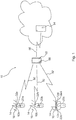
- Figure 1 shows a system for monitoring the tapping of water generally referenced with the reference numeral 10 for example in a medical facility.
- the monitoring system 10 comprises a plurality of tapping points 12a, 12b, 12c and 12d which are the end points of domestic pipe works 14 installed in or on a wall 16.
- tapping end points 12a, 12b, 12c and 12d are provided with different sanitary fittings according to the local requirements of the sanitary installations to which the tapping point 12a, 12b, 12c or 12d belongs to.
- sanitary fitting 20a is shown at the tapping point 12a which is signal line faucet for a cold water line.
- the sanitary fitting 20a comprises a tapping detection device 22a, which is configured to detect, if and when water is withdrawn from the sanitary fitting 20a and therefore from the sanitary tapping point 12a. Further details of the detection device 22a will be explained later keeping in mind that the sanitary fitting 20a exemplifies the use of an tapping detection device 22a integrated in a sanitary fitting 20a.
- FIG. 1 shows a sanitary fitting 20b which is a usual faucet without any adaptions to the present invention.
- This sanitary fitting 20b is connected via a tapping detection device 22b to the sanitary tapping point 12b.
- the tapping detection device 22b is an intermediate add-on component, which on the one side has connection means for connection with the usual sanitary fittings 20b and on the other side has a corresponding connection means for connection with the sanitary tapping point 12b. Again, details of the tapping detection device 22b will be provided later.
- FIG. 1 shows a single lever sanitary fitting as an example of a sanitary fitting 20c for a combined connection with a hot water sanitary tapping point 12c and a cold water sanitary tapping point 12d.
- the sanitary fitting 20c is shown as a wall mounted sanitary fitting 20c but could be easily conceived as a concealed sanitary fitting.
- the tapping detection devices 22a, 22b, 22c and 22d of Fig. 1 have in common that they comprise some sort of sensor which allows the tapping detection device to detect, if water is withdrawn from the sanitary tapping points 12a, 12b, 12c or 12d.
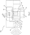
- FIG. 2 shows the intermediate tapping detection device 22b (identical to 22c or 22d) having a thermally conductive device body 26 with a water channel 28 running from a first connection means 30 to a second connection means 32.
- the tapping detection device 22b comprises a temperature sensor 34 in contact with the device body 26.
- a temperature sensor 34 in contact with the device body 26.
- an evaluation unit 36 included in the tapping detection device 22b and connected with the temperature sensor 34 is able to detect when water is withdrawn.
- Such an evaluation unit 36 may be realized using integrated electronic circuits.
- a timer 38 allows the tapping detection device 22b to correlate these detections with a time line.
- a memory 40 also included in the evaluation unit 36 allows to store these information for later use. Furthermore, the memory 40 may store a parametrization setup for the evaluation unit 36.
- Fig. 2 shows, again only exemplarily, a turbine 42 arranged in the water channel 28 of the tapping detection device 22b for providing energy to the evaluation unit 36.
- This turbine 42 may also cooperate with a hall sensor 44 which registers the movement speed of the turbine 42 in order to realize a flow meter. This information can additionally or alternatively be used by the evaluation unit 36 to detect the tapping of water.
- the tapping detection device 22b comprises transmitters 46, e.g. a wireless NFC-, RFID- or Bluetooth-transmitter.
- the monitoring system 10 further comprises tapping data relay gateway 50 e.g. a smart phone, which is able to connect with the transmitters 46 of the individual tapping detection devices 22a, 22b, 22c, 22d via a short-range wireless connection 52 in order to receive tapping data from the tapping detection devices 22a, 22b, 22c, 22d.
- the relay gateway 50 is further configured to relay these data to a monitoring node 54 via a long-range network connection 56 like WLAN, GSM and/or the internet.
- the smart phone may run a gateway software app 58.
- the monitoring node 54 may for example be a server belonging to the medical facility for which the sanitary tapping points 12a, 12b, 12c, 12d are monitored. Additionally or alternatively, the monitoring node 54 may be provided by the manufacturer of the sanitary fittings 20a respectively the tapping detection devices 22b, 22c, 22d for mounting with standard sanitary fittings 20b and 20c. The manufacturer may then provide a monitoring service for the medical facility. These may include sending a reminder to the medical facility with a list of sanitary tapping points 12a, 12b, 12c, 12d which have not been used to withdraw water and therefore need tapping in order to prevent contamination due to stagnation of water.
- the manufacturer may certify to the medical facility that the sanitation status is in accordance with any applicable hygienic regulations.
- the tapping detection device 22b for intermediate mounting between the sanitary tapping points 12b, 12c, 12d and a standard sanitary fitting 20b, 20c includes a nut as the second connection means 30 for screwing on the standard thread of the sanitary tapping points 12b, 12c, 12d and a corresponding male thread as the first connection means 32 which cooperates with the fixation nut of a standard sanitary fitting 20b, 20c.
- the tapping detection device 22b comprises a hood which comprises a sanitation status indicator 60.
- the sanitation status indicator 60 comprises three LEDs 62a, 62b and 62c, in particular in colors green, yellow and red. Such a sanitation status indicator 60 may be used to show the current sanitation status of the sanitary tapping point 12b.
- an activated green LED 62a may indicate that there was enough tapping of water from the respective sanitary tapping point 12b in a certain given time interval.
- an activated yellow LED 62b may indicate that water stagnation took place to a certain extent and tapping of water is needed in order to keep the respective sanitary tapping point 12b and the associated pipe work 14 clean.
- An activated red LED 62c may indicate that already a contamination took place due to stagnation of water and a full cycle flushing with hot water is needed to sanitize the sanitary tapping point 12b and the associated pipe work 14.
- a transmitter 46 is not really required. However, the transmitter 46 may still be used to additionally gather tapping data information as suggested by the monitoring system 10.
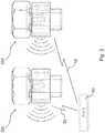
- FIG. 3 A further embodiment is shown in Fig. 3 , wherein two distinct tapping detection device 22c and 22d for mounting with a standard sanitary fitting 20c for hot and cold water sanitary tapping points 12c, 12d are provided.
- a sanitation status indicator 60 is provided.
- this sanitation status indicator 60 is provided as a separate component apart from the two tapping detection devices 22c, 22d.
- the sanitation status indicator 60 may therefore be coupled via another short-range wireless connection 52 and may be configured to receive tapping data from the two tapping detection devices 22c, 22d for hot and cold water respectively.
- the separate component could be consider to be a monitoring node 54.
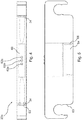
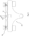
- FIGs. 4 and 5 Another embodiment is shown in Figs. 4 and 5 , wherein a tapping detection device 22e is shown which may be fitted on pipe connections towards a wall mounted hot and cold water sanitary fitting 20c.
- the tapping detection device 22e may be clipped over the two feed lines entering the hot and cold water sanitary fitting 20c.
- the tapping detection device 22e comprises two slit shaped recesses 63 for the feed lines having one open side for sliding over the feed lines.
- the tapping detection device uses two temperature sensors 34 for each feed line in order to detect the tapping of water at the respective sanitary tapping point 12c, 12d.
- Fig. 5 shows a battery 64 arranged within a battery compartment 66 of the tapping detection device 22e as a power source.
- Fig. 6 shows how the tapping detection device 22e of Fig. 4 and 5 is clipped on the feedlines of a hot and cold water sanitary fitting 20c.
Landscapes
- Engineering & Computer Science (AREA)
- Hydrology & Water Resources (AREA)
- Water Supply & Treatment (AREA)
- Public Health (AREA)
- Life Sciences & Earth Sciences (AREA)
- Health & Medical Sciences (AREA)
- General Engineering & Computer Science (AREA)
- Mechanical Engineering (AREA)
- Combustion & Propulsion (AREA)
- Physics & Mathematics (AREA)
- Thermal Sciences (AREA)
- Chemical & Material Sciences (AREA)
- Domestic Plumbing Installations (AREA)
- Selective Calling Equipment (AREA)
- Sanitary Device For Flush Toilet (AREA)
Applications Claiming Priority (1)
| Application Number | Priority Date | Filing Date | Title |
|---|---|---|---|
| DE102017128636.5A DE102017128636A1 (de) | 2017-12-01 | 2017-12-01 | Ein System, eine Einrichtung, eine Sanitärarmatur und ein Verfahren zur Zapfüberwachung |
Publications (4)
| Publication Number | Publication Date |
|---|---|
| EP3492821A2 true EP3492821A2 (fr) | 2019-06-05 |
| EP3492821A3 EP3492821A3 (fr) | 2019-06-26 |
| EP3492821B1 EP3492821B1 (fr) | 2025-11-05 |
| EP3492821C0 EP3492821C0 (fr) | 2025-11-05 |
Family
ID=64476979
Family Applications (1)
| Application Number | Title | Priority Date | Filing Date |
|---|---|---|---|
| EP18208244.6A Active EP3492821B1 (fr) | 2017-12-01 | 2018-11-26 | Système, équipement sanitaire et procédé de surveillance de la prise d'eau à partir d'une pluralité de points de prélèvement sanitaire |
Country Status (3)
| Country | Link |
|---|---|
| EP (1) | EP3492821B1 (fr) |
| DE (1) | DE102017128636A1 (fr) |
| PL (1) | PL3492821T3 (fr) |
Cited By (2)
| Publication number | Priority date | Publication date | Assignee | Title |
|---|---|---|---|---|
| CN110503737A (zh) * | 2019-08-26 | 2019-11-26 | 世纪海航(厦门)科技有限公司 | 一种基于nfc的自动考勤方法、装置、电子班牌及系统 |
| US11825251B2 (en) | 2020-06-25 | 2023-11-21 | Cornell Pump Company, Llc | Pump sensor system |
Families Citing this family (2)
| Publication number | Priority date | Publication date | Assignee | Title |
|---|---|---|---|---|
| DE102022104703B4 (de) | 2021-06-02 | 2023-03-30 | BÜSCH Management GmbH | Anordnung zum drahtlosen Auslesen von Drehbewegungsdaten eines Unterflur-Installationselements sowie Unterflur-Installationselement |
| DE102023126564A1 (de) * | 2023-09-28 | 2025-04-03 | Schell GmbH & Co. KG. | Verfahren zum Betreiben eines Gebäude-Wasserversorgungssystems mit Sanitärarmaturen |
Family Cites Families (5)
| Publication number | Priority date | Publication date | Assignee | Title |
|---|---|---|---|---|
| DE102007009007B4 (de) * | 2007-02-23 | 2010-10-21 | Frank Jobst | Vorrichtung zur Überwachung der Spülaktivitäten einer Wasserleitung |
| GB2527571B (en) * | 2014-06-26 | 2017-09-06 | Gan Livne | A compact self powered and automated attachment to a fluid system |
| GB2530004B (en) * | 2014-07-02 | 2021-01-20 | Ackw Ltd | Monitoring arrangement. |
| DE102016107695A1 (de) * | 2015-05-11 | 2016-11-17 | Wimtec Sanitärprodukte Gmbh | Verfahren zum Erfassen von Temperaturen |
| GB2542249A (en) * | 2015-08-21 | 2017-03-15 | Real Time Logistics Solutions Ltd | A hot water system which is in a building and which is for reducing the spread of a water-borne disease |
-
2017
- 2017-12-01 DE DE102017128636.5A patent/DE102017128636A1/de active Pending
-
2018
- 2018-11-26 PL PL18208244.6T patent/PL3492821T3/pl unknown
- 2018-11-26 EP EP18208244.6A patent/EP3492821B1/fr active Active
Cited By (2)
| Publication number | Priority date | Publication date | Assignee | Title |
|---|---|---|---|---|
| CN110503737A (zh) * | 2019-08-26 | 2019-11-26 | 世纪海航(厦门)科技有限公司 | 一种基于nfc的自动考勤方法、装置、电子班牌及系统 |
| US11825251B2 (en) | 2020-06-25 | 2023-11-21 | Cornell Pump Company, Llc | Pump sensor system |
Also Published As
| Publication number | Publication date |
|---|---|
| PL3492821T3 (pl) | 2026-03-16 |
| EP3492821B1 (fr) | 2025-11-05 |
| EP3492821A3 (fr) | 2019-06-26 |
| DE102017128636A1 (de) | 2019-06-06 |
| EP3492821C0 (fr) | 2025-11-05 |
Similar Documents
| Publication | Publication Date | Title |
|---|---|---|
| EP3492821B1 (fr) | Système, équipement sanitaire et procédé de surveillance de la prise d'eau à partir d'une pluralité de points de prélèvement sanitaire | |
| US12298170B2 (en) | Ultrasonic flow metering | |
| US11359991B2 (en) | System and method for water leak detection | |
| US11095960B2 (en) | Water meter and leak detection system having communication with a intelligent central hub listening and speaking apparatus, wireless thermostat and/or home automation system | |
| US11378235B2 (en) | Method and apparatus for detecting leaks in a building water system | |
| GB2553681B (en) | Flow detection device | |
| US20110035063A1 (en) | Water Management System | |
| CA3000003C (fr) | Systeme de surveillance de fluide | |
| US8907810B2 (en) | Water usage monitoring system | |
| US10642289B1 (en) | Connected mixing valve for controlling water temperature | |
| CN117242228A (zh) | 已连接的水龙头系统 | |
| GB2546126A (en) | Flow detection device | |
| JP2010194277A (ja) | おむつ監視装置 | |
| CN201935793U (zh) | 直饮水机在线漏水检测系统 | |
| KR20130064903A (ko) | 사용자를 위한 공공요금 실시간 원격 검침 시스템 | |
| DE102016107693A1 (de) | Verfahren zum Auslösen einer Stagnationsfreispülung | |
| JP5276893B2 (ja) | 居住者生存情報通知システム | |
| US12618742B2 (en) | Periodic water leak detection | |
| US20240151569A1 (en) | Consumable usage measurement using sound, temperature, and centralized analytics | |
| GB2569470B (en) | Flow detection device | |
| GB2572274A (en) | Flow detection device | |
| CN202604808U (zh) | 动物测温装置 | |
| JP2011034249A (ja) | 水管理システム | |
| JP2015032243A (ja) | 火災報知設備 | |
| GB2572705A (en) | Flow detection device |
Legal Events
| Date | Code | Title | Description |
|---|---|---|---|
| PUAI | Public reference made under article 153(3) epc to a published international application that has entered the european phase |
Free format text: ORIGINAL CODE: 0009012 |
|
| STAA | Information on the status of an ep patent application or granted ep patent |
Free format text: STATUS: THE APPLICATION HAS BEEN PUBLISHED |
|
| PUAL | Search report despatched |
Free format text: ORIGINAL CODE: 0009013 |
|
| AK | Designated contracting states |
Kind code of ref document: A2 Designated state(s): AL AT BE BG CH CY CZ DE DK EE ES FI FR GB GR HR HU IE IS IT LI LT LU LV MC MK MT NL NO PL PT RO RS SE SI SK SM TR |
|
| AX | Request for extension of the european patent |
Extension state: BA ME |
|
| AK | Designated contracting states |
Kind code of ref document: A3 Designated state(s): AL AT BE BG CH CY CZ DE DK EE ES FI FR GB GR HR HU IE IS IT LI LT LU LV MC MK MT NL NO PL PT RO RS SE SI SK SM TR |
|
| AX | Request for extension of the european patent |
Extension state: BA ME |
|
| RIC1 | Information provided on ipc code assigned before grant |
Ipc: F24D 17/00 20060101AFI20190517BHEP Ipc: E03C 1/05 20060101ALI20190517BHEP Ipc: E03C 1/10 20060101ALI20190517BHEP Ipc: E03B 7/04 20060101ALI20190517BHEP Ipc: E03C 1/00 20060101ALI20190517BHEP Ipc: E03B 7/08 20060101ALI20190517BHEP Ipc: C02F 1/02 20060101ALI20190517BHEP |
|
| STAA | Information on the status of an ep patent application or granted ep patent |
Free format text: STATUS: REQUEST FOR EXAMINATION WAS MADE |
|
| 17P | Request for examination filed |
Effective date: 20191205 |
|
| RBV | Designated contracting states (corrected) |
Designated state(s): AL AT BE BG CH CY CZ DE DK EE ES FI FR GB GR HR HU IE IS IT LI LT LU LV MC MK MT NL NO PL PT RO RS SE SI SK SM TR |
|
| STAA | Information on the status of an ep patent application or granted ep patent |
Free format text: STATUS: EXAMINATION IS IN PROGRESS |
|
| 17Q | First examination report despatched |
Effective date: 20220504 |
|
| GRAP | Despatch of communication of intention to grant a patent |
Free format text: ORIGINAL CODE: EPIDOSNIGR1 |
|
| STAA | Information on the status of an ep patent application or granted ep patent |
Free format text: STATUS: GRANT OF PATENT IS INTENDED |
|
| INTG | Intention to grant announced |
Effective date: 20250526 |
|
| GRAS | Grant fee paid |
Free format text: ORIGINAL CODE: EPIDOSNIGR3 |
|
| GRAA | (expected) grant |
Free format text: ORIGINAL CODE: 0009210 |
|
| STAA | Information on the status of an ep patent application or granted ep patent |
Free format text: STATUS: THE PATENT HAS BEEN GRANTED |
|
| AK | Designated contracting states |
Kind code of ref document: B1 Designated state(s): AL AT BE BG CH CY CZ DE DK EE ES FI FR GB GR HR HU IE IS IT LI LT LU LV MC MK MT NL NO PL PT RO RS SE SI SK SM TR |
|
| REG | Reference to a national code |
Ref country code: CH Ref legal event code: F10 Free format text: ST27 STATUS EVENT CODE: U-0-0-F10-F00 (AS PROVIDED BY THE NATIONAL OFFICE) Effective date: 20251105 Ref country code: GB Ref legal event code: FG4D |
|
| REG | Reference to a national code |
Ref country code: CH Ref legal event code: R17 Free format text: ST27 STATUS EVENT CODE: U-0-0-R10-R17 (AS PROVIDED BY THE NATIONAL OFFICE) Effective date: 20251110 |
|
| REG | Reference to a national code |
Ref country code: IE Ref legal event code: FG4D |
|
| U01 | Request for unitary effect filed |
Effective date: 20251105 |
|
| U07 | Unitary effect registered |
Designated state(s): AT BE BG DE DK EE FI FR IT LT LU LV MT NL PT RO SE SI Effective date: 20251111 |
|
| U20 | Renewal fee for the european patent with unitary effect paid |
Year of fee payment: 8 Effective date: 20251119 |
|
| REG | Reference to a national code |
Ref country code: CH Ref legal event code: U11 Free format text: ST27 STATUS EVENT CODE: U-0-0-U10-U11 (AS PROVIDED BY THE NATIONAL OFFICE) Effective date: 20260129 |
|
| PG25 | Lapsed in a contracting state [announced via postgrant information from national office to epo] |
Ref country code: ES Free format text: LAPSE BECAUSE OF FAILURE TO SUBMIT A TRANSLATION OF THE DESCRIPTION OR TO PAY THE FEE WITHIN THE PRESCRIBED TIME-LIMIT Effective date: 20251105 |
|
| PGFP | Annual fee paid to national office [announced via postgrant information from national office to epo] |
Ref country code: NO Payment date: 20260126 Year of fee payment: 8 |
|
| PG25 | Lapsed in a contracting state [announced via postgrant information from national office to epo] |
Ref country code: HR Free format text: LAPSE BECAUSE OF FAILURE TO SUBMIT A TRANSLATION OF THE DESCRIPTION OR TO PAY THE FEE WITHIN THE PRESCRIBED TIME-LIMIT Effective date: 20251105 |
|
| PG25 | Lapsed in a contracting state [announced via postgrant information from national office to epo] |
Ref country code: RS Free format text: LAPSE BECAUSE OF FAILURE TO SUBMIT A TRANSLATION OF THE DESCRIPTION OR TO PAY THE FEE WITHIN THE PRESCRIBED TIME-LIMIT Effective date: 20260205 |
|
| PG25 | Lapsed in a contracting state [announced via postgrant information from national office to epo] |
Ref country code: IS Free format text: LAPSE BECAUSE OF FAILURE TO SUBMIT A TRANSLATION OF THE DESCRIPTION OR TO PAY THE FEE WITHIN THE PRESCRIBED TIME-LIMIT Effective date: 20260305 |
|
| PGFP | Annual fee paid to national office [announced via postgrant information from national office to epo] |
Ref country code: CH Payment date: 20260129 Year of fee payment: 8 |
|
| PGFP | Annual fee paid to national office [announced via postgrant information from national office to epo] |
Ref country code: PL Payment date: 20251024 Year of fee payment: 8 |