EP3493023B1 - Power supply - Google Patents
Power supply Download PDFInfo
- Publication number
- EP3493023B1 EP3493023B1 EP17204661.7A EP17204661A EP3493023B1 EP 3493023 B1 EP3493023 B1 EP 3493023B1 EP 17204661 A EP17204661 A EP 17204661A EP 3493023 B1 EP3493023 B1 EP 3493023B1
- Authority
- EP
- European Patent Office
- Prior art keywords
- heat
- dissipating
- power supply
- circuit board
- fan
- Prior art date
- Legal status (The legal status is an assumption and is not a legal conclusion. Google has not performed a legal analysis and makes no representation as to the accuracy of the status listed.)
- Active
Links
Images




Classifications
-
- G—PHYSICS
- G06—COMPUTING OR CALCULATING; COUNTING
- G06F—ELECTRIC DIGITAL DATA PROCESSING
- G06F1/00—Details not covered by groups G06F3/00 - G06F13/00 and G06F21/00
- G06F1/16—Constructional details or arrangements
- G06F1/20—Cooling means
-
- G—PHYSICS
- G06—COMPUTING OR CALCULATING; COUNTING
- G06F—ELECTRIC DIGITAL DATA PROCESSING
- G06F1/00—Details not covered by groups G06F3/00 - G06F13/00 and G06F21/00
- G06F1/26—Power supply means, e.g. regulation thereof
-
- H—ELECTRICITY
- H05—ELECTRIC TECHNIQUES NOT OTHERWISE PROVIDED FOR
- H05K—PRINTED CIRCUITS; CASINGS OR CONSTRUCTIONAL DETAILS OF ELECTRIC APPARATUS; MANUFACTURE OF ASSEMBLAGES OF ELECTRICAL COMPONENTS
- H05K7/00—Constructional details common to different types of electric apparatus
- H05K7/20—Modifications to facilitate cooling, ventilating, or heating
- H05K7/2089—Modifications to facilitate cooling, ventilating, or heating for power electronics, e.g. for inverters for controlling motor
- H05K7/20909—Forced ventilation, e.g. on heat dissipaters coupled to components
Definitions
- the present invention is related to a power supply, particularly to a power supply using a heat-dissipating fan without a barrier wall around a fan blade set.
- each of all power supplies used in personal computers includes a fan for heat-dissipation.
- the general arrangement of the fan is disclosed in patents, such as US 20090290293 , US 20100284149 , US 20080266793 , US 6,074,296 , US 2003/202879 A1 , US 5522700A , US 2009/147478A1 and so on.
- each of all currently used fans is provided with an outer frame, via which the fan is mounted on a housing of the power supply. Additionally, a flow-guiding channel, provided for a fan blade set to be suspended therein, is further delimited by the outer frame, such that heat-dissipating airflow generated by the fan is discharged through the flow-guiding channel.
- the present invention provides a power supply, including a bottom case, a top cover, a circuit board and a heat-dissipating fan.
- the bottom case and the top cover are fitted together to delimit an accommodating space.
- the circuit board is mounted on the bottom case and located within the accommodating space.
- the circuit board is provided thereon with a plurality of electronic components and a plurality of heat-dissipating elements, each of the plurality of heat-dissipating element being provided correspondingly to one of the plurality of electronic components and allowed to conduct heat, respectively.
- Each of the plurality of heat-dissipatings elements is provided with a mounting hole.
- the heat-dissipating fan includes a supporting frame, a driving module provided on the supporting frame, and a fan blade set covering the driving module and being driven by the driving module to rotate.
- the supporting frame is presented as a flat plate and provided with a plurality of connecting ribs, each of the plurality of connecting ribs being respectively connected to one of the mounting holes.
- the heat-dissipating fan is not provided with a barrier wall around the fan blade set.
- the mounting hole is replaced by a gap formed between a plurality of fins on each of the plurality of heat-dissipating elements.
- lines interconnecting positions where the mounting holes are located are formed as a polygon.
- the plurality of heat-dissipating elements are of equal height, in such a way that top edges of the plurality of heat-dissipating elements are located on overlapping parallel lines, and each of the mounting holes is respectively located on the top edge of each of the plurality of heat-dissipating elements.
- the top cover is provided with at least one vent facing the heat-dissipating fan.
- the present invention also provides a power supply, the power supply including a bottom case, a top cover, a circuit board and a heat-dissipating fan.
- the bottom case and the top cover are fitted together to delimit an accommodating space.
- the circuit board is mounted on the bottom case and located within the accommodating space.
- the heat-dissipating fan includes a supporting frame, a driving module provided on the supporting frame, and a fan blade set covering the driving module and being driven by the driving module to rotate.
- the supporting frame is provided with a main body provided for the driving module and the fan blade set to be installed, as well as a plurality of supporting posts connected to the main body and fixed on the circuit board, respectively.
- the supporting frame is not provided with a barrier wall around the fan blade set.
- the top cover is provided with at least one vent facing the heat-dissipating fan.
- each of the plurality of supporting posts and the main body are two members, which may be separated from each other.
- lines interconnecting positions where the plurality of supporting posts are located on the circuit board are formed as a polygon.
- the supporting frame is provided with a plurality of connecting ribs, each of the plurality of connecting ribs being respectively provided between two adjacent of the plurality of supporting posts.
- the heat-dissipating fan disclosed in the present invention being not provided with a barrier wall around the fan blade set.
- the heat-dissipating fan of the present invention is not provided with an outer frame.
- the heat-dissipating airflow generated by the heat-dissipating fan is not restricted by the outer frame any more in the present invention, while heat dissipation in relation to each of the plurality of electronic components or member within the accommodating space is allowed so as to further enhance effect of heat-dissipation in comparison with the conventional art.
- the heat-dissipating fan of the present invention is not provided with an outer frame so as to decrease the noise produced by the heat-dissipating fan from working.
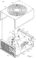
- the present invention provides a power supply 10.
- the power supply 10 may be implemented according to the ATX specification.
- the power supply 10 includes a bottom case 11, a top cover 12, a circuit board 13 and a heat-dissipating fan 14.
- the bottom case 11 and the top cover 12 may be presented in the form of a mutually fitted structure.
- each of the bottom case 11 and the top cover 12 is formed as U-shaped structure, respectively, such that the bottom case 11 and the top cover 12 are fitted together to delimit an accommodating space 15.
- the top cover 12 may be provided with a vent 121.
- the bottom case 11 and the top cover 12 may be implemented with many components according to the design. Furthermore, the bottom case 11 may be further mounted at the sides thereof with a power input port 111 and at least one power output port 112. The power input port 111 and the power output port 112 are provided at different sides of the bottom case 11. The number of the power output ports 112 may be modified as required for implementation.
- the circuit board 13 is mounted on the bottom case 11 and located within the accommodating space 15.
- the circuit board 13 is laid thereon with a plurality of electronic components 131 and a plurality of heat-dissipating elements 132, each of the plurality of heat-dissipating elements 132 being provided correspondingly to one of the plurality of electronic components 131, respectively.
- the plurality of electronic components 131 are combined as at least a power calibration circuit, an electric power conversion circuit and etc., after being arranged.
- each of plurality of the heat-dissipating elements 132 is contacted with one of the plurality of electronic components 131, to which each of the plurality of heat-dissipating elements 132 is provided correspondingly, so as to conduct heat.
- Each of the plurality of heat-dissipating elements 132 is provided with a mounting hole 133.
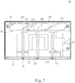
- the plurality of heat-dissipating elements 132 are of equal height, in such a way that top edges 134 of the plurality of heat-dissipating elements 132 are located on overlapping parallel lines 60.
- each of the mounting holes 133 is located on the top edge 134 of each of the plurality of heat-dissipating elements 132, respectively.
- the mounting hole 133 referred to in the present invention may be replaced by a gap 136 formed between a plurality of fins 135 on the plurality of heat-dissipating elements 132, just as illustrated in Fig. 2 .
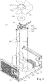
- the heat-dissipating fan 14 of this embodiment includes a supporting frame 141, a driving module 142 provided on the supporting frame 141, and a fan blade set 143 covering the driving module 142 and being driven by the driving module 142 to rotate.
- the heat-dissipating fan 14 is further connected to a power feeder (not illustrated in this figure) on the circuit board 13 via a power line 144, so as to acquire electric power required for rotation.
- the driving module 142 is implemented as an electric motor configuration.
- the supporting frame 141 of the present invention is presented as a flat plate and provided with a plurality of connecting ribs 145, each of the plurality of connecting ribs 145 being connected to one of the mounting holes 133, respectively.
- each of the plurality of connecting ribs 145 may be modified in accordance with the position or pattern of each of the plurality of heat-dissipating elements 132 on which the mounting hole 133 is provided.
- the heat-dissipating fan 14 of the present invention is not provided with a barrier wall, which is provided around the fan blade set 143.
- the heat-dissipating fan 14 is not provided with a flow-limiting channel, which is delimited by an outer frame and in which the fan blade set 143 is suspended. In this way, the heat-dissipating fan 14 is allowed for generating heat-dissipating airflow within the accommodating space 15 more specifically when operated electrically, so as to enhance the heat-dissipation performance.
- the mounting holes 133 may be mapped out, such that a polygon 61 is formed by lines interconnecting positions where the mounting holes 133 are located. In this way, the heat-dissipating fan 14 may be supported more stably, so as to reduce the possibility of sway of the heat-dissipating fan 14 during rotation.
- the amount of the mounting hole 133 used in the embodiment of the present invention may be, for example but not limited to, three. Other appropriate amount of the mounting hole 133 is also applicable in the present invention.
- the power supply 20 includes a bottom case 21, a top cover 22, a circuit board 23 and a heat-dissipating fan 24.
- the bottom case 21 and the top cover 22 are fitted together to delimit an accommodating space 25.
- the top cover 22 may be provided with at least one vent 221 facing the heat-dissipating fan 24.
- the circuit board 23 is mounted on the bottom case 21 and located within the accommodating space 25.
- the circuit board 23 is laid with a plurality of electronic components 231 and the plurality of heat-dissipating elements 232 as required for implementation.
- the electronic components 231 are combined as a power calibration circuit, an electric power conversion circuit and etc., after being arranged.
- the plurality of heat-dissipating elements 232 may be laid as required for implementation.
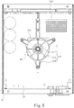
- the heat-dissipating fan 24 includes a supporting frame 241, a driving module 242 provided on the supporting frame 241, and a fan blade set 243 covering the driving module 242 and being driven by the driving module 242 to rotate.
- the supporting frame 241 is provided with a main body 244 provided for the driving module 242 and the fan blade set 243 to be installed, as well as a plurality of supporting posts 245 connected to the main body 244 and fixed on the circuit board 23, respectively. More specifically, the main body 244 is presented as a flat plate.
- the main body 244 is provided with at least a flat portion 246 provided for the driving module 242 to be placed, as well as a protruding portion 247 connected to the flat portion 246 and located at the center of the main body 244 for the fan blade set 243 to be fitted.
- the main body 244 further includes a plurality of connecting portions 248 extending from the edge of the flat portion 246, respectively. Each of the connecting portions 248 is corresponded to one of the plurality of supporting posts 245, respectively.
- the circuit board 23 is provided with a plurality of through-holes 233 provided for the plurality of supporting posts 245 to be installed, respectively.
- the main body 244 is held up by the plurality of supporting posts 245 together, such that the main body 244 is installed at a height 62 relative to the circuit board 23, in which each of the plurality of supporting posts 245 is at least higher than the highest one of the electronic components 231.
- each of the plurality of supporting posts 245 and the main body 244 are two members, which may be separated from each other.
- the heat-dissipating fan 24 of this embodiment is not provided with a barrier wall, which is provided around the fan blade set 243; that is to say, the heat-dissipating fan 24 is not provided with a flow-limiting channel, which is delimited by an outer frame and in which the fan blade set 243 is suspended.
- the positions where the plurality of supporting posts 245 are located on the circuit board 23 may be mapped out, such that a polygon 63 is formed by lines interconnecting positions where the plurality of supporting posts 245 are located on the circuit board 23.
- the amount of the supporting post 245 used in the embodiment may be, for example but not limited to, three. Other appropriate amount of the supporting post 245 is also applicable in the present invention.
- a fixing component 30 is further implemented with each of the plurality of supporting posts 245, and fixing each of the plurality of supporting posts 245 on the circuit board 23, wherein the fixing component 30 may be a nut, a screw, and so on.
- the supporting frame 241 in one embodiment may be provided with a plurality of connecting ribs 249, each of the plurality of connecting ribs 249 being provided between two adjacent of the plurality of supporting posts 245, respectively.
- the plurality of connecting ribs 249 may be provided for enhancing the structural strength of the plurality of supporting posts 245.
- the pattern of the plurality of connecting ribs 249 may be modified as required for implementation.
- the top cover 22 is provided thereon with at least one vent 221 facing the heat-dissipating fan 24.
- the top cover 22 is provided thereon with the vents 221, and the vents 221 may be laid out and then formed in accordance with a designed pattern.
- the decorative baffle 26 may be provided with a plurality of air-permeable holes 261, which are cuttingly provided in accordance with a designed pattern, just as illustrated in Fig. 10 .
- the power supply 20 is provided for a user with a choice among a variety of the decorative baffles 26 on the basis of personal preference.
Landscapes
- Engineering & Computer Science (AREA)
- Theoretical Computer Science (AREA)
- Physics & Mathematics (AREA)
- General Engineering & Computer Science (AREA)
- General Physics & Mathematics (AREA)
- Microelectronics & Electronic Packaging (AREA)
- Thermal Sciences (AREA)
- Human Computer Interaction (AREA)
- Cooling Or The Like Of Electrical Apparatus (AREA)
Priority Applications (2)
| Application Number | Priority Date | Filing Date | Title |
|---|---|---|---|
| PL17204661T PL3493023T3 (pl) | 2017-11-30 | 2017-11-30 | Zasilacz |
| EP17204661.7A EP3493023B1 (en) | 2017-11-30 | 2017-11-30 | Power supply |
Applications Claiming Priority (1)
| Application Number | Priority Date | Filing Date | Title |
|---|---|---|---|
| EP17204661.7A EP3493023B1 (en) | 2017-11-30 | 2017-11-30 | Power supply |
Publications (2)
| Publication Number | Publication Date |
|---|---|
| EP3493023A1 EP3493023A1 (en) | 2019-06-05 |
| EP3493023B1 true EP3493023B1 (en) | 2021-07-07 |
Family
ID=60543402
Family Applications (1)
| Application Number | Title | Priority Date | Filing Date |
|---|---|---|---|
| EP17204661.7A Active EP3493023B1 (en) | 2017-11-30 | 2017-11-30 | Power supply |
Country Status (2)
| Country | Link |
|---|---|
| EP (1) | EP3493023B1 (pl) |
| PL (1) | PL3493023T3 (pl) |
Families Citing this family (6)
| Publication number | Priority date | Publication date | Assignee | Title |
|---|---|---|---|---|
| CN113162154B (zh) * | 2021-03-27 | 2024-06-18 | 深圳市鑫嘉恒科技有限公司 | 一种带有散热功能的充电器 |
| CN114173528A (zh) * | 2021-11-02 | 2022-03-11 | 深圳市博德越科技有限公司 | 数据采集卡 |
| CN114745881B (zh) * | 2022-03-07 | 2024-03-29 | 西北工业大学太仓长三角研究院 | 一种多元数据分析式多用途车载智能化电子系统 |
| CN114513918B (zh) * | 2022-03-30 | 2023-12-05 | 天长市森林电器科技有限公司 | 一种电动车充电器保护盒 |
| CN219068051U (zh) * | 2022-12-16 | 2023-05-23 | 苏州汇川控制技术有限公司 | 变频器机芯及变频器 |
| WO2024208014A1 (zh) * | 2023-04-04 | 2024-10-10 | 北京嘉楠捷思信息技术有限公司 | 计算设备 |
Family Cites Families (7)
| Publication number | Priority date | Publication date | Assignee | Title |
|---|---|---|---|---|
| GB2298520B (en) * | 1995-03-03 | 1999-09-08 | Hong Chen Fu In | Heat sink device for integrated circuit |
| TW407741U (en) | 1998-05-21 | 2000-10-01 | Delta Electronics Inc | Securing device |
| TW592343U (en) * | 2002-04-30 | 2004-06-11 | Delta Electronics Inc | Improved cooling fan |
| US7515412B2 (en) | 2007-04-26 | 2009-04-07 | Enermax Technology Corporation | Cooling structure for power supply |
| US8365811B2 (en) * | 2007-12-07 | 2013-02-05 | Nidec Corporation | Heat sink fan |
| TW200949495A (en) | 2008-05-21 | 2009-12-01 | Compucase Entpr Co Ltd | Power supply |
| US20100284149A1 (en) | 2009-05-05 | 2010-11-11 | Enermax Technology Corporation | Power supply and a housing structure with the power supply |
-
2017
- 2017-11-30 PL PL17204661T patent/PL3493023T3/pl unknown
- 2017-11-30 EP EP17204661.7A patent/EP3493023B1/en active Active
Non-Patent Citations (1)
| Title |
|---|
| None * |
Also Published As
| Publication number | Publication date |
|---|---|
| EP3493023A1 (en) | 2019-06-05 |
| PL3493023T3 (pl) | 2022-01-24 |
Similar Documents
| Publication | Publication Date | Title |
|---|---|---|
| US10362711B2 (en) | Fan mounting arrangement in a power supply | |
| US10285306B1 (en) | Power supply | |
| EP3493023B1 (en) | Power supply | |
| US8514574B2 (en) | Heat dissipating apparatus | |
| US8072753B2 (en) | Computer system | |
| US20130094140A1 (en) | Motherboard module and electronic apparatus using the same | |
| US20120327589A1 (en) | Computer system with airflow guiding duct | |
| US7656659B2 (en) | Notebook computer with thermal module | |
| US8144459B2 (en) | Heat dissipating system with fan module | |
| TWI475363B (zh) | 具有散熱結構之電子裝置 | |
| US6951446B2 (en) | Fan cover heat dissipation assembly for a host computer CPU | |
| US8248779B2 (en) | Computer and fixing bracket thereof | |
| US11397453B2 (en) | Heat dissipation system | |
| US20090268394A1 (en) | Heat-radiating microcomputer case | |
| TW201424547A (zh) | 電子裝置組合 | |
| CN103904813B (zh) | 一种大功率电机散热结构 | |
| US8085536B2 (en) | Computer | |
| US20070230113A1 (en) | Rackmount server with fans installed next to a side of a housing | |
| TWI716739B (zh) | 電源供應器 | |
| US20070076371A1 (en) | Electronic devices with heat-dissipation apparatuses | |
| JP2019054055A (ja) | ファンユニット及び電子機器 | |
| TWI654919B (zh) | Power Supplier | |
| CN207460715U (zh) | 电源供应器 | |
| CN101165356B (zh) | 散热装置及其离心风扇与使用该散热装置的电子装置 | |
| CN210639565U (zh) | 显示卡散热模组 |
Legal Events
| Date | Code | Title | Description |
|---|---|---|---|
| PUAI | Public reference made under article 153(3) epc to a published international application that has entered the european phase |
Free format text: ORIGINAL CODE: 0009012 |
|
| STAA | Information on the status of an ep patent application or granted ep patent |
Free format text: STATUS: THE APPLICATION HAS BEEN PUBLISHED |
|
| AK | Designated contracting states |
Kind code of ref document: A1 Designated state(s): AL AT BE BG CH CY CZ DE DK EE ES FI FR GB GR HR HU IE IS IT LI LT LU LV MC MK MT NL NO PL PT RO RS SE SI SK SM TR |
|
| AX | Request for extension of the european patent |
Extension state: BA ME |
|
| STAA | Information on the status of an ep patent application or granted ep patent |
Free format text: STATUS: REQUEST FOR EXAMINATION WAS MADE |
|
| 17P | Request for examination filed |
Effective date: 20191030 |
|
| RBV | Designated contracting states (corrected) |
Designated state(s): AL AT BE BG CH CY CZ DE DK EE ES FI FR GB GR HR HU IE IS IT LI LT LU LV MC MK MT NL NO PL PT RO RS SE SI SK SM TR |
|
| STAA | Information on the status of an ep patent application or granted ep patent |
Free format text: STATUS: EXAMINATION IS IN PROGRESS |
|
| 17Q | First examination report despatched |
Effective date: 20200612 |
|
| GRAP | Despatch of communication of intention to grant a patent |
Free format text: ORIGINAL CODE: EPIDOSNIGR1 |
|
| STAA | Information on the status of an ep patent application or granted ep patent |
Free format text: STATUS: GRANT OF PATENT IS INTENDED |
|
| INTG | Intention to grant announced |
Effective date: 20210126 |
|
| GRAS | Grant fee paid |
Free format text: ORIGINAL CODE: EPIDOSNIGR3 |
|
| GRAA | (expected) grant |
Free format text: ORIGINAL CODE: 0009210 |
|
| STAA | Information on the status of an ep patent application or granted ep patent |
Free format text: STATUS: THE PATENT HAS BEEN GRANTED |
|
| AK | Designated contracting states |
Kind code of ref document: B1 Designated state(s): AL AT BE BG CH CY CZ DE DK EE ES FI FR GB GR HR HU IE IS IT LI LT LU LV MC MK MT NL NO PL PT RO RS SE SI SK SM TR |
|
| REG | Reference to a national code |
Ref country code: GB Ref legal event code: FG4D |
|
| REG | Reference to a national code |
Ref country code: AT Ref legal event code: REF Ref document number: 1409204 Country of ref document: AT Kind code of ref document: T Effective date: 20210715 |
|
| REG | Reference to a national code |
Ref country code: DE Ref legal event code: R096 Ref document number: 602017041563 Country of ref document: DE |
|
| REG | Reference to a national code |
Ref country code: IE Ref legal event code: FG4D |
|
| REG | Reference to a national code |
Ref country code: LT Ref legal event code: MG9D |
|
| REG | Reference to a national code |
Ref country code: NL Ref legal event code: MP Effective date: 20210707 |
|
| REG | Reference to a national code |
Ref country code: AT Ref legal event code: MK05 Ref document number: 1409204 Country of ref document: AT Kind code of ref document: T Effective date: 20210707 |
|
| PG25 | Lapsed in a contracting state [announced via postgrant information from national office to epo] |
Ref country code: AT Free format text: LAPSE BECAUSE OF FAILURE TO SUBMIT A TRANSLATION OF THE DESCRIPTION OR TO PAY THE FEE WITHIN THE PRESCRIBED TIME-LIMIT Effective date: 20210707 Ref country code: BG Free format text: LAPSE BECAUSE OF FAILURE TO SUBMIT A TRANSLATION OF THE DESCRIPTION OR TO PAY THE FEE WITHIN THE PRESCRIBED TIME-LIMIT Effective date: 20211007 Ref country code: LT Free format text: LAPSE BECAUSE OF FAILURE TO SUBMIT A TRANSLATION OF THE DESCRIPTION OR TO PAY THE FEE WITHIN THE PRESCRIBED TIME-LIMIT Effective date: 20210707 Ref country code: ES Free format text: LAPSE BECAUSE OF FAILURE TO SUBMIT A TRANSLATION OF THE DESCRIPTION OR TO PAY THE FEE WITHIN THE PRESCRIBED TIME-LIMIT Effective date: 20210707 Ref country code: FI Free format text: LAPSE BECAUSE OF FAILURE TO SUBMIT A TRANSLATION OF THE DESCRIPTION OR TO PAY THE FEE WITHIN THE PRESCRIBED TIME-LIMIT Effective date: 20210707 Ref country code: NO Free format text: LAPSE BECAUSE OF FAILURE TO SUBMIT A TRANSLATION OF THE DESCRIPTION OR TO PAY THE FEE WITHIN THE PRESCRIBED TIME-LIMIT Effective date: 20211007 Ref country code: PT Free format text: LAPSE BECAUSE OF FAILURE TO SUBMIT A TRANSLATION OF THE DESCRIPTION OR TO PAY THE FEE WITHIN THE PRESCRIBED TIME-LIMIT Effective date: 20211108 Ref country code: NL Free format text: LAPSE BECAUSE OF FAILURE TO SUBMIT A TRANSLATION OF THE DESCRIPTION OR TO PAY THE FEE WITHIN THE PRESCRIBED TIME-LIMIT Effective date: 20210707 Ref country code: SE Free format text: LAPSE BECAUSE OF FAILURE TO SUBMIT A TRANSLATION OF THE DESCRIPTION OR TO PAY THE FEE WITHIN THE PRESCRIBED TIME-LIMIT Effective date: 20210707 Ref country code: RS Free format text: LAPSE BECAUSE OF FAILURE TO SUBMIT A TRANSLATION OF THE DESCRIPTION OR TO PAY THE FEE WITHIN THE PRESCRIBED TIME-LIMIT Effective date: 20210707 Ref country code: HR Free format text: LAPSE BECAUSE OF FAILURE TO SUBMIT A TRANSLATION OF THE DESCRIPTION OR TO PAY THE FEE WITHIN THE PRESCRIBED TIME-LIMIT Effective date: 20210707 |
|
| PG25 | Lapsed in a contracting state [announced via postgrant information from national office to epo] |
Ref country code: LV Free format text: LAPSE BECAUSE OF FAILURE TO SUBMIT A TRANSLATION OF THE DESCRIPTION OR TO PAY THE FEE WITHIN THE PRESCRIBED TIME-LIMIT Effective date: 20210707 Ref country code: GR Free format text: LAPSE BECAUSE OF FAILURE TO SUBMIT A TRANSLATION OF THE DESCRIPTION OR TO PAY THE FEE WITHIN THE PRESCRIBED TIME-LIMIT Effective date: 20211008 |
|
| REG | Reference to a national code |
Ref country code: DE Ref legal event code: R097 Ref document number: 602017041563 Country of ref document: DE |
|
| PG25 | Lapsed in a contracting state [announced via postgrant information from national office to epo] |
Ref country code: DK Free format text: LAPSE BECAUSE OF FAILURE TO SUBMIT A TRANSLATION OF THE DESCRIPTION OR TO PAY THE FEE WITHIN THE PRESCRIBED TIME-LIMIT Effective date: 20210707 |
|
| PLBE | No opposition filed within time limit |
Free format text: ORIGINAL CODE: 0009261 |
|
| STAA | Information on the status of an ep patent application or granted ep patent |
Free format text: STATUS: NO OPPOSITION FILED WITHIN TIME LIMIT |
|
| PG25 | Lapsed in a contracting state [announced via postgrant information from national office to epo] |
Ref country code: SM Free format text: LAPSE BECAUSE OF FAILURE TO SUBMIT A TRANSLATION OF THE DESCRIPTION OR TO PAY THE FEE WITHIN THE PRESCRIBED TIME-LIMIT Effective date: 20210707 Ref country code: SK Free format text: LAPSE BECAUSE OF FAILURE TO SUBMIT A TRANSLATION OF THE DESCRIPTION OR TO PAY THE FEE WITHIN THE PRESCRIBED TIME-LIMIT Effective date: 20210707 Ref country code: RO Free format text: LAPSE BECAUSE OF FAILURE TO SUBMIT A TRANSLATION OF THE DESCRIPTION OR TO PAY THE FEE WITHIN THE PRESCRIBED TIME-LIMIT Effective date: 20210707 Ref country code: EE Free format text: LAPSE BECAUSE OF FAILURE TO SUBMIT A TRANSLATION OF THE DESCRIPTION OR TO PAY THE FEE WITHIN THE PRESCRIBED TIME-LIMIT Effective date: 20210707 Ref country code: CZ Free format text: LAPSE BECAUSE OF FAILURE TO SUBMIT A TRANSLATION OF THE DESCRIPTION OR TO PAY THE FEE WITHIN THE PRESCRIBED TIME-LIMIT Effective date: 20210707 Ref country code: AL Free format text: LAPSE BECAUSE OF FAILURE TO SUBMIT A TRANSLATION OF THE DESCRIPTION OR TO PAY THE FEE WITHIN THE PRESCRIBED TIME-LIMIT Effective date: 20210707 |
|
| 26N | No opposition filed |
Effective date: 20220408 |
|
| PG25 | Lapsed in a contracting state [announced via postgrant information from national office to epo] |
Ref country code: MC Free format text: LAPSE BECAUSE OF FAILURE TO SUBMIT A TRANSLATION OF THE DESCRIPTION OR TO PAY THE FEE WITHIN THE PRESCRIBED TIME-LIMIT Effective date: 20210707 |
|
| REG | Reference to a national code |
Ref country code: CH Ref legal event code: PL |
|
| PG25 | Lapsed in a contracting state [announced via postgrant information from national office to epo] |
Ref country code: LU Free format text: LAPSE BECAUSE OF NON-PAYMENT OF DUE FEES Effective date: 20211130 Ref country code: IT Free format text: LAPSE BECAUSE OF FAILURE TO SUBMIT A TRANSLATION OF THE DESCRIPTION OR TO PAY THE FEE WITHIN THE PRESCRIBED TIME-LIMIT Effective date: 20210707 Ref country code: BE Free format text: LAPSE BECAUSE OF NON-PAYMENT OF DUE FEES Effective date: 20211130 |
|
| REG | Reference to a national code |
Ref country code: BE Ref legal event code: MM Effective date: 20211130 |
|
| PG25 | Lapsed in a contracting state [announced via postgrant information from national office to epo] |
Ref country code: LI Free format text: LAPSE BECAUSE OF NON-PAYMENT OF DUE FEES Effective date: 20211130 Ref country code: CH Free format text: LAPSE BECAUSE OF NON-PAYMENT OF DUE FEES Effective date: 20211130 |
|
| PG25 | Lapsed in a contracting state [announced via postgrant information from national office to epo] |
Ref country code: IE Free format text: LAPSE BECAUSE OF NON-PAYMENT OF DUE FEES Effective date: 20211130 |
|
| PG25 | Lapsed in a contracting state [announced via postgrant information from national office to epo] |
Ref country code: CY Free format text: LAPSE BECAUSE OF FAILURE TO SUBMIT A TRANSLATION OF THE DESCRIPTION OR TO PAY THE FEE WITHIN THE PRESCRIBED TIME-LIMIT Effective date: 20210707 |
|
| PG25 | Lapsed in a contracting state [announced via postgrant information from national office to epo] |
Ref country code: HU Free format text: LAPSE BECAUSE OF FAILURE TO SUBMIT A TRANSLATION OF THE DESCRIPTION OR TO PAY THE FEE WITHIN THE PRESCRIBED TIME-LIMIT; INVALID AB INITIO Effective date: 20171130 |
|
| PGFP | Annual fee paid to national office [announced via postgrant information from national office to epo] |
Ref country code: GB Payment date: 20231130 Year of fee payment: 7 |
|
| PGFP | Annual fee paid to national office [announced via postgrant information from national office to epo] |
Ref country code: FR Payment date: 20231130 Year of fee payment: 7 Ref country code: DE Payment date: 20231130 Year of fee payment: 7 |
|
| PGFP | Annual fee paid to national office [announced via postgrant information from national office to epo] |
Ref country code: PL Payment date: 20231120 Year of fee payment: 7 |
|
| PG25 | Lapsed in a contracting state [announced via postgrant information from national office to epo] |
Ref country code: MK Free format text: LAPSE BECAUSE OF FAILURE TO SUBMIT A TRANSLATION OF THE DESCRIPTION OR TO PAY THE FEE WITHIN THE PRESCRIBED TIME-LIMIT Effective date: 20210707 |
|
| PG25 | Lapsed in a contracting state [announced via postgrant information from national office to epo] |
Ref country code: TR Free format text: LAPSE BECAUSE OF FAILURE TO SUBMIT A TRANSLATION OF THE DESCRIPTION OR TO PAY THE FEE WITHIN THE PRESCRIBED TIME-LIMIT Effective date: 20210707 |
|
| PG25 | Lapsed in a contracting state [announced via postgrant information from national office to epo] |
Ref country code: MT Free format text: LAPSE BECAUSE OF FAILURE TO SUBMIT A TRANSLATION OF THE DESCRIPTION OR TO PAY THE FEE WITHIN THE PRESCRIBED TIME-LIMIT Effective date: 20210707 |
|
| REG | Reference to a national code |
Ref country code: DE Ref legal event code: R119 Ref document number: 602017041563 Country of ref document: DE |
|
| GBPC | Gb: european patent ceased through non-payment of renewal fee |
Effective date: 20241130 |
|
| PG25 | Lapsed in a contracting state [announced via postgrant information from national office to epo] |
Ref country code: DE Free format text: LAPSE BECAUSE OF NON-PAYMENT OF DUE FEES Effective date: 20250603 |
|
| PG25 | Lapsed in a contracting state [announced via postgrant information from national office to epo] |
Ref country code: GB Free format text: LAPSE BECAUSE OF NON-PAYMENT OF DUE FEES Effective date: 20241130 |
|
| PG25 | Lapsed in a contracting state [announced via postgrant information from national office to epo] |
Ref country code: FR Free format text: LAPSE BECAUSE OF NON-PAYMENT OF DUE FEES Effective date: 20241130 |