EP3493036A1 - Panneau tactile ionique - Google Patents
Panneau tactile ionique Download PDFInfo
- Publication number
- EP3493036A1 EP3493036A1 EP17834628.4A EP17834628A EP3493036A1 EP 3493036 A1 EP3493036 A1 EP 3493036A1 EP 17834628 A EP17834628 A EP 17834628A EP 3493036 A1 EP3493036 A1 EP 3493036A1
- Authority
- EP
- European Patent Office
- Prior art keywords
- touch
- hydrogel
- ionic
- touch panel
- current
- Prior art date
- Legal status (The legal status is an assumption and is not a legal conclusion. Google has not performed a legal analysis and makes no representation as to the accuracy of the status listed.)
- Granted
Links
Images








Classifications
-
- G—PHYSICS
- G06—COMPUTING OR CALCULATING; COUNTING
- G06F—ELECTRIC DIGITAL DATA PROCESSING
- G06F3/00—Input arrangements for transferring data to be processed into a form capable of being handled by the computer; Output arrangements for transferring data from processing unit to output unit, e.g. interface arrangements
- G06F3/01—Input arrangements or combined input and output arrangements for interaction between user and computer
- G06F3/03—Arrangements for converting the position or the displacement of a member into a coded form
- G06F3/041—Digitisers, e.g. for touch screens or touch pads, characterised by the transducing means
- G06F3/044—Digitisers, e.g. for touch screens or touch pads, characterised by the transducing means by capacitive means
-
- G—PHYSICS
- G01—MEASURING; TESTING
- G01N—INVESTIGATING OR ANALYSING MATERIALS BY DETERMINING THEIR CHEMICAL OR PHYSICAL PROPERTIES
- G01N27/00—Investigating or analysing materials by the use of electric, electrochemical, or magnetic means
- G01N27/26—Investigating or analysing materials by the use of electric, electrochemical, or magnetic means by investigating electrochemical variables; by using electrolysis or electrophoresis
- G01N27/28—Electrolytic cell components
- G01N27/30—Electrodes, e.g. test electrodes; Half-cells
- G01N27/333—Ion-selective electrodes or membranes
- G01N27/3335—Ion-selective electrodes or membranes the membrane containing at least one organic component
-
- G—PHYSICS
- G06—COMPUTING OR CALCULATING; COUNTING
- G06F—ELECTRIC DIGITAL DATA PROCESSING
- G06F3/00—Input arrangements for transferring data to be processed into a form capable of being handled by the computer; Output arrangements for transferring data from processing unit to output unit, e.g. interface arrangements
- G06F3/01—Input arrangements or combined input and output arrangements for interaction between user and computer
- G06F3/03—Arrangements for converting the position or the displacement of a member into a coded form
- G06F3/041—Digitisers, e.g. for touch screens or touch pads, characterised by the transducing means
-
- G—PHYSICS
- G06—COMPUTING OR CALCULATING; COUNTING
- G06F—ELECTRIC DIGITAL DATA PROCESSING
- G06F3/00—Input arrangements for transferring data to be processed into a form capable of being handled by the computer; Output arrangements for transferring data from processing unit to output unit, e.g. interface arrangements
- G06F3/01—Input arrangements or combined input and output arrangements for interaction between user and computer
- G06F3/03—Arrangements for converting the position or the displacement of a member into a coded form
- G06F3/041—Digitisers, e.g. for touch screens or touch pads, characterised by the transducing means
- G06F3/0412—Digitisers structurally integrated in a display
-
- G—PHYSICS
- G06—COMPUTING OR CALCULATING; COUNTING
- G06F—ELECTRIC DIGITAL DATA PROCESSING
- G06F3/00—Input arrangements for transferring data to be processed into a form capable of being handled by the computer; Output arrangements for transferring data from processing unit to output unit, e.g. interface arrangements
- G06F3/01—Input arrangements or combined input and output arrangements for interaction between user and computer
- G06F3/03—Arrangements for converting the position or the displacement of a member into a coded form
- G06F3/041—Digitisers, e.g. for touch screens or touch pads, characterised by the transducing means
- G06F3/0416—Control or interface arrangements specially adapted for digitisers
-
- G—PHYSICS
- G06—COMPUTING OR CALCULATING; COUNTING
- G06F—ELECTRIC DIGITAL DATA PROCESSING
- G06F3/00—Input arrangements for transferring data to be processed into a form capable of being handled by the computer; Output arrangements for transferring data from processing unit to output unit, e.g. interface arrangements
- G06F3/01—Input arrangements or combined input and output arrangements for interaction between user and computer
- G06F3/03—Arrangements for converting the position or the displacement of a member into a coded form
- G06F3/041—Digitisers, e.g. for touch screens or touch pads, characterised by the transducing means
- G06F3/045—Digitisers, e.g. for touch screens or touch pads, characterised by the transducing means using resistive elements, e.g. a single continuous surface or two parallel surfaces put in contact
-
- G—PHYSICS
- G06—COMPUTING OR CALCULATING; COUNTING
- G06F—ELECTRIC DIGITAL DATA PROCESSING
- G06F2203/00—Indexing scheme relating to G06F3/00 - G06F3/048
- G06F2203/041—Indexing scheme relating to G06F3/041 - G06F3/045
- G06F2203/04102—Flexible digitiser, i.e. constructional details for allowing the whole digitising part of a device to be flexed or rolled like a sheet of paper
-
- G—PHYSICS
- G06—COMPUTING OR CALCULATING; COUNTING
- G06F—ELECTRIC DIGITAL DATA PROCESSING
- G06F2203/00—Indexing scheme relating to G06F3/00 - G06F3/048
- G06F2203/041—Indexing scheme relating to G06F3/041 - G06F3/045
- G06F2203/04111—Cross over in capacitive digitiser, i.e. details of structures for connecting electrodes of the sensing pattern where the connections cross each other, e.g. bridge structures comprising an insulating layer, or vias through substrate
Definitions
- the present invention relates to an ionic touch panel, and more particularly, to an ionic touch panel using hydrogel for a touch panel and having flexibility, stretchability, and biocompatibility.
- Touch panels have been continuously developed, and have become popular. Touch systems are indispensable to current electronic devices and applications thereof. As a simple and intuitive interface, a touch panel may be integrated into a display and may save the space of a display device. Touch panels may be divided into resistive sensing systems, electrostatic sensing systems, etc. and may be used in mobile phones, computers, ticket machines, information kiosks, etc.
- a transparent electrode film needs to be used to implement a resistive or electrostatic touch sensing system.
- ITO indium tin oxide
- next-generation touch panels are expected to be used in flexible devices, wearable devices, and even devices integrable into body parts. Since demands for human-computer interaction increase, the next-generation touch panels are required to have high stretchability, flexibility, and biocompatibility.
- ITO indium tin oxide
- a polymer electrode material such as indium tin oxide (ITO)
- CNT carbon nanotubes
- metal nanowires etc.
- ITO indium tin oxide
- these materials have sheet resistances rapidly increasing when stretched, and exert fatigue failure when repeatedly stretched.
- biocompatibility of the materials has not been verified, more research is needed on integrability into a body part.
- the present invention provides an ionic touch panel having a high stretchability, a high flexibility, and a high visible light transmittance.
- the present invention also provides a biocompatible ionic touch panel integrable into a body part and thus usable as a next-generation touch panel.
- a biocompatible ionic touch panel integrable into a body part and thus usable as a next-generation touch panel.
- the scope of the present invention range is not limited thereto.
- an ionic touch panel including a hydrogel touch unit containing salt, and electrodes connected to at least two parts of the hydrogel touch unit.
- touch currents may be induced from the electrodes to a touch point.
- the salt may have a molar concentration of 0.01M to 2M.
- Magnitudes of a baseline current and a touch current flowing through the hydrogel touch unit may decrease as the molar concentration of the salt increases.
- the hydrogel touch unit may have a transmittance of 98% in a visible light band.
- a baseline current and a touch current flowing through the hydrogel touch unit may increase.
- the hydrogel touch unit may have a strip, rectangular, or circular shape.
- the hydrogel touch unit may have a strip shape, and the electrodes may be connected to two ends of the hydrogel touch unit.
- I 1 a current measured at an end of the hydrogel touch unit
- I 2 a current measured at the other end of the hydrogel touch unit
- the hydrogel touch unit may have a rectangular shape, and the electrodes may be connected to four corners of the hydrogel touch unit.
- touch currents may be induced from the electrodes connected to the corners, to a touch point, and a location of the touch point may be calculated based on values of the touch currents.
- a magnitude of a touch current induced from a corner to the touch point may increase as a distance between the corner and the touch point decreases.
- ⁇ and ⁇ may be calculated using Equation (1) expressed as ⁇ ⁇ (I 2 +I 3 )/(I 1 +I 2 +I 3 +I 4 ) and Equation (2) expressed as ⁇ ⁇ (I 1 +I 2 )/(I 1 +I 2 +I 3 +I 4 ) (where I 1 , I 2 , I 3 , and I 4 denote currents measured at the four corners of the hydrogel touch unit).
- the hydrogel touch unit may be attached to a substrate, and the substrate may be integrable into and insulative to a body part.
- the substrate may have a thickness of 1mm to 6mm.
- a method of manufacturing an ionic touch panel including preparing a hydrogel solution by dissolving hydrogel monomer powder and salt in deionized (DI) water and then sequentially adding a cross-linking agent of hydrogel, an initiator, and an accelerator to the solution, producing the hydrogel solution into a hydrogel touch unit having a certain shape, and connecting electrodes to at least two parts of the hydrogel touch unit.
- DI deionized
- an ionic touch panel system including an ionic touch panel including a hydrogel touch unit containing salt, and electrodes connected to at least two parts of the hydrogel touch unit, a controller board electrically connected to the ionic touch panel to calculate a location of a touch point, and a terminal device for receiving location information of the touch point from the controller board, and displaying the location information.
- an ionic touch panel having a high stretchability, a high flexibility, and a high visible light transmittance may be provided.
- a biocompatible ionic touch panel integrable into a body part and thus usable as a next-generation touch panel may be provided.
- Ionic touch panels 10 to 40 according to the present invention are characterized in that hydrogel 100 containing ionic salt is used and in that electrodes 200 are connected to parts of the hydrogel 100.
- operating principles of a one-dimensional (1D) ionic touch panel 10 will be mainly described according to a first embodiment, and actual implementation of a 2D ionic touch panel 20 expanded from the 1D ionic touch panel 10 will be described according to a second embodiment.
- Stretchability of an ionic touch panel 30 will be mainly described according to a third embodiment, and application of an ionic touch panel 40 as an epidermal touch panel integrable into or attachable to a body part will be described according to a fourth embodiment.
- the operating principles and structure of the ionic touch panel 10 according to the first embodiment are equally applicable to the ionic touch panels 20, 30, and 40 according to the second to fourth embodiments.
- FIG. 1 is a schematic view of a strip-shaped ionic touch panel 10 according to a first embodiment of the present invention.
- the strip-shaped ionic touch panel 10 may be understood as a 1D ionic touch panel 10.
- the ionic touch panel 10 includes a hydrogel touch unit 100 and electrodes 200 (including 210 and 220).
- the ionic touch panel 10 may further include current meters 300 for measuring currents flowing through the hydrogel touch unit 100, and a power source 400 for applying a voltage to the hydrogel touch unit 100 through the electrodes 200.
- the hydrogel touch unit 100 may include hydrogel, and more particularly, hydrogel containing salt. Since a user of the ionic touch panel 10 touches the surface of the hydrogel, the hydrogel (i.e., the hydrogel containing salt) is referred to as the hydrogel touch unit 100 in this specification.
- Hydrogel is a hydrophilic polymer network swollen with a large amount of water. Hydrogel is as soft as tissues and has a very high stretchability. Most types of hydrogel are biocompatible and thus may be used to deliver drugs, replace tissues, and treat wounds. Some types of hydrogel have a transmittance of 99% in an entire visible light band and thus may clearly transmit optical data. Hydrogel contains a large amount of water and thus may be used as an ionic conductor by dissolving ions in the water. Accordingly, the present invention may use hydrogel for a touch panel to utilize high stretchability, biocompatibility, and transmittance of the hydrogel.
- the present invention uses polyacrylamide (PAAm) gel but is not limited thereto.
- hydrogel Any known type of hydrogel may also be used as long as high stretchability, biocompatibility, and transmittance are achievable.
- gel containing another ionic solvent such as PAAm, polyhydroxyethylmethacrylate, or polyvinyl alcohol may also be used.
- the hydrogel touch unit 100 may contain ionic salt.
- the ionic salt may include chlorine (Cl)-based salt meltable in water (e.g., LiCl, NaCl, CaCl 2 , KCl, MgCl, or BaCl 2 ), (NO 3 ) - , SO 4 2- , or S - .
- any known type of salt may also be used as long as ions are formable in an aqueous solution.
- the salt allows a current to flow due to motion of ions in the hydrogel touch unit 100.
- a LiCI aqueous solution has hygroscopic properties for absorbing moisture and thus may be used as an evaporation inhibitor to prevent evaporation of moisture from the hydrogel.
- a molar concentration of the salt may be determined considering moisture evaporation and resistivity of the hydrogel and is not particularly limited.
- the ionic touch panel 10-40 may calculate a location of a touch point by detecting a variation in capacitance on the ionic touch panel 10.
- the electrodes 200 may be connected to at least two parts of the hydrogel touch unit 100.
- the electrodes 200 may use metal (e.g., platinum (Pt), copper (Cu), silver (Ag), gold (Au), molybdenum (Mo), or aluminum (Al)), a transparent material, polymer, graphene, or the like. Particularly, using Pt, Au, Ag, or the like as the material of the electrodes 200, current loss may be reduced and conductivity may be increased.
- the power source 400 may apply an alternating current (AC) voltage of, for example, -10V to 10V within a stable range in which an electrochemical reaction does not occur.
- AC alternating current
- the hydrogel touch unit 100 is provided in a strip shape having a size of 2cm (width) ⁇ 15cm (length) ⁇ 3mm (thickness), and uses PAAm gel containing a 2M LiCI aqueous solution as salt.
- Acrylamide (AAm) (Sigma, A8887) and LiCI (Sigma, L4408) are used as base materials of the hydrogel touch unit 100, and N,N-methylenebisacrylamide (MBAA) (Sigma, M7279) is used as a cross-linking agent of the AAm gel.
- Ammonium persulfate (AP) (Sigma, A9164) and N,N,N',N'-tetramethylethylenediamine (TEMED) (Sigma, T7024) are used as a thermal initiator and a gelling accelerator, respectively.
- the hydrogel touch unit 100 is synthesized by dissolving AAm monomer powder and LiCI in deionized (DI) water.
- Molar concentrations of AAm and LiCI are 2.17M and 2M, and the cross-linking agent (i.e., MBAA) and the initiator (i.e., AP) are added by 0.06wt% and 0.16wt% with respect to the AAm monomer.
- the mixture is sonicated and degassed in a vacuum chamber, and then the accelerator (i.e., TEMED) is lastly added by 0.25wt% with respect to the AAm monomer.
- the solution is poured into an acrylic mold in different sizes and shapes, and the hydrogel touch unit 100 is prepared after an hour.
- the Pt electrodes 200 may be provided at two ends of the hydrogel touch unit 100 and may be connected to the AC power source 400 (e.g., a function generator (Model 33612A, Agilent)).
- the two current meters 300 (including 310 and 320; Model 34461A, Agilent) are provided at two ends of the strip-shaped hydrogel touch unit 100 to measure root mean square (RMS) values of alternating currents.
- a driving voltage may be -0.6V to 0.6V, and a frequency may be 10kHz to 100kHz.
- a finger 500 When the strip-shaped hydrogel touch unit 100 is touched, a finger 500 may be capacitively connected to the hydrogel touch unit 100 such that a current may flow through the finger 500 to the ground.
- the ionic touch panel 10 of FIG. 1 may include resistive parts and a capacitive part.
- the resistive parts indicate virtual parts of the strip-shaped hydrogel touch unit 100 divided by a touch point.
- a left part of the touch point may have a length of ⁇ L and a right part thereof may have a length of (1- ⁇ )L.
- a resistance may be determined to be linearly proportional to a length virtually divided from the point ⁇ .
- the capacitive part may have a constant value given by an electrical double layer (EDL) and the finger 500.
- EDL electrical double layer
- FIG. 2 is a view showing an electrical circuit in a case when the ionic touch panel 10 according to the first embodiment of the present invention is touched.
- the ionic touch panel 10 is divided into two resistive parts by a touch point.
- Each resistor is connected to a capacitor C EDL in series with an EDL and the current meter 300 (e.g., 310 or 320), and the two resistive parts have a parallel form.
- Such a parallel circuit may be connected in series with a capacitor C finger generated by the finger 500.
- the effect of the capacitor C EDL generated by the EDL may be ignored.
- a current may flow through the hydrogel touch unit 100 to the grounded finger 500.
- the current passes through the capacitors C EDL and resistors R 1 and R 2 of the hydrogel touch unit 100 and then passes through the capacitor C finger (hereinafter, the current passing through the capacitor C finger is called a "touch current"). Therefore, current measurement by the current meters 300 relates to only the resistors R 1 and R 2 , the capacitors C EDL , and the capacitor C finger .
- R 2 1 ⁇ ⁇ R
- Impedances Z of the two divided paths are expressed as shown in Equation 3.
- Z 1 R 1 ⁇ j 1 / 2 ⁇ fC EDL
- Z 2 R 2 ⁇ j 1 / 2 ⁇ fC EDL
- Equation 4 A total current of the circuit is expressed as shown in Equation 4, and currents of the two paths are expressed as shown in Equations 5 and 6.
- I total V / R 1 R 2 / R 1 + R 2 ⁇ j 1 / 2 ⁇ fC finger
- Equations 1 and 2 are substituted in Equations 5 and 6, Equations 7 and 8 are obtained as shown below.
- location information of the touch point may be obtained based on I 1 and I 2 .
- FIG. 3 is a graph showing a current measurement result of the ionic touch panel 10 according to the first embodiment of the present invention, based on a touch location.
- FIG. 4 shows a parasitic capacitance and a baseline current of an ionic touch panel according to an embodiment of the present invention.
- the baseline current may be understood as a parasitic current corresponding to a parasitic capacitance generated between the hydrogel touch unit 100 and a peripheral environment such as a circuit.
- the baseline current occurs due to a parasitic current corresponding to a parasitic capacitance.
- the baseline current flows through an electrical path of the peripheral environment to the ground.
- the parasitic capacitance is a significant factor for determining the baseline current that can be considered as a noise signal, and efforts for reducing the baseline current are required.
- the hydrogel touch unit 100 when the hydrogel touch unit 100 is touched with the finger 500, an additional current from the electrode 200 to the finger 500 occurs, and the current meter 300 may detect a sum of the baseline current and the additionally induced current.
- the induced current may be called a "touch current" as described above.
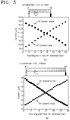
- FIG. 5 illustrates graphs showing the relationship between a touch location and a measured current in the ionic touch panel 10 according to the first embodiment of the present invention.
- Touch currents are proportional to proximities from the electrodes 200 to a touch point.
- the strip-shaped hydrogel touch unit 100 having a length of 15cm is touched at every 1cm from a left end to a right end thereof, and currents measured by an A1 current meter 310 and an A2 current meter 320 are shown in (a) of FIG. 5 .
- I 1 linearly decreases.
- the strip-shaped hydrogel touch unit 100 is deformable and stretchable.
- an area of the strip-shaped hydrogel touch unit 100 may increase and thus a parasitic capacitance may also increase. Accordingly, compared to a state before being stretched, both a baseline current and a touch current may increase.
- the current behavior in the stretched state based on the interval of touch points is as shown in (b) of FIG. 5 , and is similar to that shown in (a) of FIG. 5 .
- FIG. 6 illustrates graphs showing a resistance and a touch current of an ionic touch panel 10 according to an embodiment of the present invention, based on a molar concentration. The relationship between a molar concentration of salt and a resistance and a current of hydrogel will be described with reference to FIG. 6 .
- R ⁇ ⁇ L / S (where S denotes a cross-sectional area of a hydrogel touch unit and L denotes a length of the hydrogel touch unit.)
- the relationship between the molar concentration and the current is as shown in (b) of FIG. 6 .
- I V/R.
- the current does not follow Ohm's Law. Instead, the highest current value is measured at the lowest molar concentration, 0.01M (the highest resistance), and the lowest current value is measured at the highest molar concentration, 2M (the lowest resistance).
- Volatility of hydrogel is a significant factor for maintaining the shape of the hydrogel in the air. Due to hygroscopic properties for preventing evaporation of moisture from the hydrogel, LiCI salt is used as a charge carrier for a touch panel.
- FIG. 7 is a graph showing a volatility test result of an ionic touch panel 10, 20, 30 or 40 according to an embodiment of the present invention, based on time.
- Volatilities of three hydrogel samples including LiCI, NaCl, and DI water are compared.
- the samples may have a diameter of 2cm and a thickness of 3mm, and may be cut (with a power of 80% and at a speed of 3cm/sec.) using a laser cutter (VLS3.50, Universal Laser System).
- the volatilities are measured using a vacuum desiccator and a diaphragm vacuum pump (MZ 2C-NT, c).
- MZ 2C-NT, c diaphragm vacuum pump
- the pressure inside the desiccator is equal to or lower than 0.02atm. It is shown that the LiCI hydrogel sample has a high humidity-maintaining effect in a vacuum state compared to the NaCI and DI water hydrogel samples.
- a 2D ionic touch panel 20 expanded from the 1D ionic touch panel 10 will now be described.
- FIG. 8 is a schematic view of a rectangular ionic touch panel 20 according to a second embodiment of the present invention.
- FIG. 9 is a view showing example touch points TP1 to TP4 of the ionic touch panel 20 according to the second embodiment of the present invention.
- the rectangular ionic touch panel 20 may be understood as a 2D ionic touch panel 20.
- Pt electrodes 200 may be connected to four corners of a rectangular hydrogel touch unit 100.
- Four current meters 300 may be provided between the power source 400 and the four corners.
- Two standardized distances ⁇ and ⁇ are used to indicate a touch location.
- a bottom left end of the rectangular hydrogel touch unit 100 may be indicated by (0.0) and a top right end thereof may be indicated by (1.1).
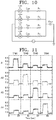
- FIG. 10 is a view showing an electrical circuit in a case when the ionic touch panel 20 according to the second embodiment of the present invention is touched.
- the rectangular hydrogel touch unit 100 When the rectangular hydrogel touch unit 100 is touched with the finger 500, a closed circuit may be generated as illustrated in FIG. 10 .
- the rectangular hydrogel touch unit 100 may be divided into four virtual resistive parts by a touch point. The four resistive parts are connected in parallel with each other, and such a parallel circuit may be connected in series with a capacitor C finger generated by the finger 500.
- FIG. 11 is a graph showing a current measurement result of the ionic touch panel 20 according to the second embodiment of the present invention, based on the touch points TP1 to TP4.
- Currents may be measured by A1 to A4 current meters 310 to 340 located at the corners. As shown in FIG. 11 , when the touch point TP1 is touched, the highest current value is measured by the A1 current meters 310 closest to the touch point TP1, and the lowest current value is measured by the A3 current meters 330 farthest from the touch point TP1.
- the 2D ionic touch panel 20 Similarly to the strip-shaped ionic touch panel 10, in the 2D ionic touch panel 20, current values are measured in proportion to proximities between the electrodes 200 (including 210 to 240) and the touch points TP1 to TP4. Location information of a touch point on the 2D ionic touch panel 20 may be calculated based on the current values.
- FIG. 12 is a block diagram of a touch panel system according to an embodiment of the present invention.
- a controller board 70 may be designed for communications between the ionic touch panel 10-40 and a computer 90.
- a driving signal unit 77 may generate a driving voltage signal which may be applied to the electrodes 200 of the ionic touch panel 10-40.
- the controller board 70 may measure a current of several mA flowing through each electrode 200, and an alternating current (AC)-to-direct current (DC) converter 71 may convert the current into a DC current.
- an amplification unit 73 may amplify the current, and an analog-to-digital converter 75 may convert the current into a digital current signal.
- the controller board 70 may calculate the location of the touch point based on the currents.
- Location information may be transmitted to the computer 90, and the computer 90 may display the location information on a monitor M1 or M2 (see FIG. 13 ).
- the computer 90 is illustrated as an example, the computer 90 may be replaced by a terminal device such as a smartphone, a personal digital assistant (PDA), or a tablet.
- the ionic touch panel 10-40, the controller board 70, and the computer (or terminal device) 90 are illustrated as separate elements, the three elements may be integrated into a single device.
- the ionic touch panel 10-40 may be provided on a surface of a smartphone, a central processing unit (CPU) of the smartphone may serve as the controller board 70, and a display of the smartphone may display the location information instead of the monitor M1 or M2.
- CPU central processing unit
- the location information of the touch point may be expressed as shown in Equations 10 and 11.
- the currents increased by the touch and measured by the A1 to A4 current meters 310 to 340 are denoted by I 1 to I 4 .
- I 1 to I 4 The currents increased by the touch and measured by the A1 to A4 current meters 310 to 340 are denoted by I 1 to I 4 .
- Equation 10 when points with the same ⁇ coordinate are touched, equal values are calculated by Equation 10. For example, for the touch points (0.25, 0.25) and (0.25, 0.75), equal values of 0.517 are calculated by Equation 10.
- the principle of the ⁇ coordinate is equally applicable to a ⁇ coordinate.
- FIGS. 13 and 14 illustrate images showing a driving operation of the ionic touch panel 20 according to the second embodiment of the present invention.
- the rectangular ionic touch panel 20 having an input figure displayed thereon may be attached to a monitor1 M1.
- a polymethyl methacrylate (PMMA) plate having a thickness of 1mm may be inserted between the ionic touch panel 20 and the monitor1 M1 as an electrical insulator.
- PMMA polymethyl methacrylate
- the ionic touch panel 20 is connected through the controller board 70 to the computer 90.
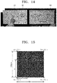
- the computer 90 may display an output figure on a monitor2 M2 based on location information received from the controller board 70. Some distortion is observed at corners of the output figure. As shown in FIG. 14 , when two rectangles having the same center are drawn, distortion more severely occurs in an outer rectangle.
- FIG. 15 is a view showing a boundary condition of the ionic touch panel 20 according to the second embodiment of the present invention.
- FIG. 16 illustrates graphs showing a current simulation result of the ionic touch panel 20 according to the second embodiment of the present invention.
- an electrical finite element simulation is performed.
- the boundary condition is illustrated in FIG. 15 , and currents flowing through four corners with respect to various touch points ( ⁇ , ⁇ ) are calculated.
- a uniform electrical conductivity e.g., 1 S/m
- the ionic touch panel 20 is divided into 10 grids in a matrix. Cross points of the grids, which are regarded as touch points, are sequentially grounded (0V), and coordinates ( ⁇ , ⁇ ) are calculated based on distances of the grids.
- FIG. 17 shows images of a circular ionic touch panel 30 ((a) of FIG. 17 ) and a stretched ionic touch panel 30' ((b) of FIG. 17 ) according to a third embodiment of the present invention.
- FIG. 18 is an image showing a driving operation of the ionic touch panel 30' according to the third embodiment of the present invention.
- FIG. 19 is a graph showing a transmittance of the hydrogel touch unit 100 according to an embodiment of the present invention, in a visible light band.
- the circular ionic touch panel 30 having a diameter of 4cm and a biaxial stretcher are prepared.
- the circular ionic touch panel 30 is attached to the biaxial stretcher and is connected through the Pt electrodes 200 to the controller board 70.
- an area thereof increases to about 1,000%.
- the ionic touch panel 30' may also be driven in the stretched state and, for example, a star may be drawn using the stretched ionic touch panel 30'.
- FIG. 20 is a graph showing a current measurement result before and after the ionic touch panel 30 according to the third embodiment of the present invention is stretched.
- A1 current values of center touch points of the ionic touch panels 30 and 30' are measured as shown in FIG. 20 .
- a baseline current increases from 6.76 ⁇ A to 8.66 ⁇ A .
- the increase in the baseline current is regarded as being caused by an increase in an area due to the stretching and by bad insulation from a ground environment, e.g., the air.
- the stretched ionic touch panel 30' When the stretched ionic touch panel 30' is touched, a touch current is added to the baseline current.
- the touch current in the stretched state is 0.53A, which is similar to a touch current of 0.48A in the state before being stretched. Even when stretched, a touch current is hardly influenced. The inversely proportional relationship between a distance and a current is maintained in the stretched state.
- FIG. 21 is a graph showing a current measurement result of the ionic touch panel 30' according to the third embodiment of the present invention, based on the touch points TP1 to TP4.
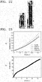
- FIG. 22 is an image of a mechanical-electrical tester for measuring repeated stretchability of an ionic touch panel according to an embodiment of the present invention.
- FIG. 23 illustrates graphs showing test results using the tester of FIG. 22 .
- a resistance of the hydrogel is measured using Pt electrodes and an LCR meter (E4980AL-100, Agilent).
- Two clamps (7cm ⁇ 2cm ⁇ 3mm) are attached to 5mm-points from upper and lower ends of the strip-shaped hydrogel. Two ends of the hydrogel are connected through the Pt electrodes to the LCR meter, and upper and lower parts of the strip-shaped hydrogel to which the Pt electrodes are connected are not stretched during the repeated stretchability test. When not deformed, the length of a substantially stretchable part between the two clamps is 12cm.
- the test is performed by a testing machine with a 50N capacity load cell (Instron model 3343).
- Ionic Touch Panel 40 as Epidermal Touch Panel
- an ionic touch panel 40 integrable into or attachable to a body part will now be described.
- an ionic touch panel 40 according to a fourth embodiment is called an epidermal touch panel.
- FIG. 24 is a schematic view of an ionic touch panel 40 configured as an epidermal touch panel, according to a fourth embodiment of the present invention.
- FIG. 25 is an image showing that the epidermal touch panel 40 according to the fourth embodiment of the present invention is attached to a body part.
- the epidermal touch panel 40 may be configured by mounting the hydrogel touch unit 100 on a substrate 600.
- the electrodes 200 may be connected to corners of the hydrogel touch unit 100.
- the substrate 600 may attach the hydrogel touch unit 100 to a body part and, at the same time, insulate the hydrogel touch unit 100.
- the substrate 600 may use 1mm VHBTM film (3M).
- the substrate 600 is not limited thereto and any other known attachment means capable of insulating the hydrogel touch unit 100 and attaching the hydrogel touch unit 100 to a body part may also be used.
- the epidermal touch panel 40 may be attached to a body part such as an arm.
- the epidermal touch panel 40 is completely transparent and thus visual content behind the epidermal touch panel 40 may be transmitted therethrough.
- the epidermal touch panel 40 is soft and stretchable and thus may allow comfortable motion when worn by a user.
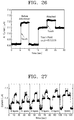
- FIG. 26 is a graph showing a current measurement result before and after the substrate 600 is attached to the ionic touch panel 40 according to the fourth embodiment of the present invention.
- FIG. 27 is a graph showing current variations of the ionic touch panel 40 according to the fourth embodiment of the present invention, based on the thickness of the substrate 600.
- a baseline current increases after the substrate 600 is attached to the hydrogel touch unit 100.
- an acrylic plate having a thickness of 1mm is used as the substrate 600.
- the thickness of the substrate 600 is reduced from 6mm to 1mm based on time.
- a leakage current is reduced by about 0.02mA whenever the thickness of the substrate 600 is reduced by 1mm.
- a current induced due to attachment of the epidermal touch panel 40 including the substrate 600 having a thickness of 1mm is 0.25mA.
- the current signal has a value sufficient to detect a touch location.
- the epidermal touch panel 40 When the epidermal touch panel 40 is attached to the skin, a leakage current increases through the skin and thus a baseline current also increases. As a result, the increase in the leakage current causes an increase in a baseline current and a reduction in a touch current. Since the reduction in the touch current influences sensitivity of the epidermal touch panel 40, insulation of the epidermal touch panel 40 needs to be considered all the time. In the epidermal touch panel 40 of the present invention, although a low leakage current flows through the skin in spite of the insulating substrate 600, since a measurable touch current is detected due to a touch, the epidermal touch panel 40 may be normally driven on the skin.
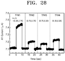
- FIG. 28 is a graph showing a current measurement result of the ionic touch panel 40 according to the fourth embodiment of the present invention, based on the touch points TP1 to TP4.
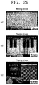
- FIG. 29 illustrates images showing various application examples of the ionic touch panel 40 according to the fourth embodiment of the present invention.
- the touch points TP1 to TP4 on the epidermal touch panel 40 are sequentially touched, and currents from the A1 current meter 310 are measured.
- An increase in a current due to a touch is 0.6 ⁇ A to 1.4 ⁇ A before the epidermal touch panel 40 is attached to a body part, and is reduced to 0.07 ⁇ A to 0.34 ⁇ A after the epidermal touch panel 40 is attached to a body part.
- attachment of the epidermal touch panel 40 to a body part does not influence the relationship between a current and a touch location.
- the epidermal touch panel 40 of the present invention may detect various motions such as tapping, holding, dragging, and swiping, and may be used to write letters, play music, play chess, etc. through appropriate motions.
Landscapes
- Engineering & Computer Science (AREA)
- General Engineering & Computer Science (AREA)
- Theoretical Computer Science (AREA)
- Physics & Mathematics (AREA)
- General Physics & Mathematics (AREA)
- Human Computer Interaction (AREA)
- Chemical & Material Sciences (AREA)
- Health & Medical Sciences (AREA)
- Life Sciences & Earth Sciences (AREA)
- Molecular Biology (AREA)
- Chemical Kinetics & Catalysis (AREA)
- Electrochemistry (AREA)
- Analytical Chemistry (AREA)
- Biochemistry (AREA)
- General Health & Medical Sciences (AREA)
- Immunology (AREA)
- Pathology (AREA)
- Measurement And Recording Of Electrical Phenomena And Electrical Characteristics Of The Living Body (AREA)
Applications Claiming Priority (2)
| Application Number | Priority Date | Filing Date | Title |
|---|---|---|---|
| KR1020160097219A KR101768648B1 (ko) | 2016-07-29 | 2016-07-29 | 이온성 터치 패널 |
| PCT/KR2017/006182 WO2018021684A1 (fr) | 2016-07-29 | 2017-06-14 | Panneau tactile ionique |
Publications (3)
| Publication Number | Publication Date |
|---|---|
| EP3493036A1 true EP3493036A1 (fr) | 2019-06-05 |
| EP3493036A4 EP3493036A4 (fr) | 2019-08-14 |
| EP3493036B1 EP3493036B1 (fr) | 2023-06-14 |
Family
ID=59753165
Family Applications (1)
| Application Number | Title | Priority Date | Filing Date |
|---|---|---|---|
| EP17834628.4A Active EP3493036B1 (fr) | 2016-07-29 | 2017-06-14 | Panneau tactile ionique |
Country Status (5)
| Country | Link |
|---|---|
| US (1) | US10860148B2 (fr) |
| EP (1) | EP3493036B1 (fr) |
| JP (1) | JP6966533B2 (fr) |
| KR (1) | KR101768648B1 (fr) |
| WO (1) | WO2018021684A1 (fr) |
Families Citing this family (4)
| Publication number | Priority date | Publication date | Assignee | Title |
|---|---|---|---|---|
| CN107291296A (zh) * | 2017-07-03 | 2017-10-24 | 京东方科技集团股份有限公司 | 触控感应结构、工作方法、触控基板、制作方法、触控显示装置 |
| EP4167065B1 (fr) | 2021-08-25 | 2026-01-28 | Seoul National University R&DB Foundation | Capteur tactile triborésistif |
| WO2023027303A1 (fr) * | 2021-08-25 | 2023-03-02 | 서울대학교산학협력단 | Capteur tactile triborésistif |
| KR102752565B1 (ko) | 2022-07-22 | 2025-01-10 | 세메스 주식회사 | 기판 처리 장치 및 기판 처리 방법 |
Family Cites Families (13)
| Publication number | Priority date | Publication date | Assignee | Title |
|---|---|---|---|---|
| US4853493A (en) * | 1988-05-06 | 1989-08-01 | Scriptel Holding, Inc. | Electrographic apparatus |
| DE69932662T2 (de) * | 1998-03-12 | 2007-08-09 | Tyco Electronics Corp. | Berührungsempfindlicher Widerstandsbildschirm |
| CN103076906B (zh) | 2011-10-26 | 2017-02-15 | 宸鸿科技(厦门)有限公司 | 触控面板及其制作方法 |
| WO2014052470A1 (fr) * | 2012-09-25 | 2014-04-03 | Arizona Board Of Regents Acting For And On Behalf Of Arizona State University | Transducteur de pression électrochimique |
| KR102242947B1 (ko) | 2013-03-11 | 2021-04-22 | 유니버시티 오브 유타 리서치 파운데이션 | 센서 시스템들 |
| US10302586B2 (en) | 2013-04-10 | 2019-05-28 | President And Fellows Of Harvard College | Stretchable ionics for transparent sensors and actuators |
| CN105144035B (zh) * | 2013-04-26 | 2019-03-22 | 意美森公司 | 利用触觉单元阵列模拟有形用户界面交互和手势 |
| AU2014274726B2 (en) * | 2013-06-06 | 2018-07-19 | Tricord Holdings, L.L.C. | Modular physiologic monitoring systems, kits, and methods |
| EP3227730A4 (fr) * | 2014-12-03 | 2018-08-01 | University Of British Columbia | Capteur transparent souple à matériau ioniquement conducteur |
| EP3265767B1 (fr) * | 2015-03-06 | 2020-02-26 | The University Of British Columbia | Procédé et capteur pour l'identification de pression sur la base d'un signal électrique généré par la redistribution d'ions mobiles dans une couche piézo-ionique |
| WO2017040851A1 (fr) * | 2015-09-01 | 2017-03-09 | President And Fellows Of Harvard College | Hydrogels dotés de propriétés mécaniques améliorées à des températures inférieures à la température de gel de l'eau |
| EP3469323A4 (fr) * | 2016-06-08 | 2020-03-18 | The University of British Columbia | Réseaux de capteurs de surface utilisant un matériau conducteur d'ions |
| CN107316945B (zh) * | 2017-06-23 | 2019-06-07 | 京东方科技集团股份有限公司 | 一种oled显示面板和oled显示装置 |
-
2016
- 2016-07-29 KR KR1020160097219A patent/KR101768648B1/ko active Active
-
2017
- 2017-06-14 JP JP2019503251A patent/JP6966533B2/ja active Active
- 2017-06-14 WO PCT/KR2017/006182 patent/WO2018021684A1/fr not_active Ceased
- 2017-06-14 EP EP17834628.4A patent/EP3493036B1/fr active Active
- 2017-06-14 US US16/321,090 patent/US10860148B2/en active Active
Also Published As
| Publication number | Publication date |
|---|---|
| WO2018021684A1 (fr) | 2018-02-01 |
| US10860148B2 (en) | 2020-12-08 |
| KR101768648B1 (ko) | 2017-08-17 |
| EP3493036B1 (fr) | 2023-06-14 |
| JP2019525332A (ja) | 2019-09-05 |
| JP6966533B2 (ja) | 2021-11-17 |
| EP3493036A4 (fr) | 2019-08-14 |
| US20190163300A1 (en) | 2019-05-30 |
Similar Documents
| Publication | Publication Date | Title |
|---|---|---|
| CN108415634B (zh) | 一种触控装置 | |
| EP3493036B1 (fr) | Panneau tactile ionique | |
| EP2958000B1 (fr) | Panneau et circuit de détection tactiles | |
| JP6100588B2 (ja) | タッチパネル用フィルム、及びそのフィルムと共に用いるスタイラスペン | |
| US20100001975A1 (en) | Portable computer | |
| US20170228065A1 (en) | Force-touch sensor with multilayered electrodes | |
| US20010033274A1 (en) | Method and apparatus for erasing previously entered data | |
| TW201013484A (en) | Device and method for detecting position of object and image display system using the same device | |
| JP5961467B2 (ja) | タッチパネル | |
| CN102597927A (zh) | 输入装置以及其装置的触控位置侦测方法 | |
| CN106873814A (zh) | 一种控制方法及电子设备 | |
| TW200949660A (en) | Coordinate detecting device and method | |
| CN102760003B (zh) | 触摸屏触摸点的检测方法 | |
| US9710094B2 (en) | Touch inputting device controlling apparatus and touch inputting device controlling method | |
| CN103186266A (zh) | 调整触控面板灵敏度的方法 | |
| TWI570608B (zh) | 壓力感測觸控面板、壓力感測方法、壓力感測之電子裝置及其控制單元 | |
| CN101430630B (zh) | 触控装置及其判断触控方式的方法 | |
| JP6104764B2 (ja) | タッチパネル用フィルム | |
| TWI658384B (zh) | 觸控面板及觸控偵測電路 | |
| JP6104767B2 (ja) | タッチパネル用カバー材、及びそのカバー材を用いたタッチパネル | |
| JP7847271B2 (ja) | タッチセンサ及び表示装置 | |
| CN104182110B (zh) | 电阻式触控面板 | |
| TWI738438B (zh) | 觸控感測器的觸控點感知方法 | |
| CN114967959A (zh) | 电子装置及触控侦测方法 | |
| JP2010086088A (ja) | 座標入力システム |
Legal Events
| Date | Code | Title | Description |
|---|---|---|---|
| STAA | Information on the status of an ep patent application or granted ep patent |
Free format text: STATUS: THE INTERNATIONAL PUBLICATION HAS BEEN MADE |
|
| PUAI | Public reference made under article 153(3) epc to a published international application that has entered the european phase |
Free format text: ORIGINAL CODE: 0009012 |
|
| STAA | Information on the status of an ep patent application or granted ep patent |
Free format text: STATUS: REQUEST FOR EXAMINATION WAS MADE |
|
| 17P | Request for examination filed |
Effective date: 20190124 |
|
| AK | Designated contracting states |
Kind code of ref document: A1 Designated state(s): AL AT BE BG CH CY CZ DE DK EE ES FI FR GB GR HR HU IE IS IT LI LT LU LV MC MK MT NL NO PL PT RO RS SE SI SK SM TR |
|
| AX | Request for extension of the european patent |
Extension state: BA ME |
|
| A4 | Supplementary search report drawn up and despatched |
Effective date: 20190712 |
|
| RIC1 | Information provided on ipc code assigned before grant |
Ipc: G01N 27/333 20060101ALI20190708BHEP Ipc: G06F 3/041 20060101AFI20190708BHEP Ipc: G06F 3/045 20060101ALI20190708BHEP Ipc: G06F 3/044 20060101ALI20190708BHEP |
|
| DAV | Request for validation of the european patent (deleted) | ||
| DAX | Request for extension of the european patent (deleted) | ||
| STAA | Information on the status of an ep patent application or granted ep patent |
Free format text: STATUS: EXAMINATION IS IN PROGRESS |
|
| 17Q | First examination report despatched |
Effective date: 20200724 |
|
| GRAP | Despatch of communication of intention to grant a patent |
Free format text: ORIGINAL CODE: EPIDOSNIGR1 |
|
| STAA | Information on the status of an ep patent application or granted ep patent |
Free format text: STATUS: GRANT OF PATENT IS INTENDED |
|
| INTG | Intention to grant announced |
Effective date: 20230102 |
|
| GRAS | Grant fee paid |
Free format text: ORIGINAL CODE: EPIDOSNIGR3 |
|
| GRAA | (expected) grant |
Free format text: ORIGINAL CODE: 0009210 |
|
| STAA | Information on the status of an ep patent application or granted ep patent |
Free format text: STATUS: THE PATENT HAS BEEN GRANTED |
|
| AK | Designated contracting states |
Kind code of ref document: B1 Designated state(s): AL AT BE BG CH CY CZ DE DK EE ES FI FR GB GR HR HU IE IS IT LI LT LU LV MC MK MT NL NO PL PT RO RS SE SI SK SM TR |
|
| REG | Reference to a national code |
Ref country code: CH Ref legal event code: EP |
|
| REG | Reference to a national code |
Ref country code: DE Ref legal event code: R096 Ref document number: 602017070273 Country of ref document: DE |
|
| REG | Reference to a national code |
Ref country code: AT Ref legal event code: REF Ref document number: 1579701 Country of ref document: AT Kind code of ref document: T Effective date: 20230715 |
|
| REG | Reference to a national code |
Ref country code: LT Ref legal event code: MG9D |
|
| REG | Reference to a national code |
Ref country code: NL Ref legal event code: MP Effective date: 20230614 |
|
| PG25 | Lapsed in a contracting state [announced via postgrant information from national office to epo] |
Ref country code: SE Free format text: LAPSE BECAUSE OF FAILURE TO SUBMIT A TRANSLATION OF THE DESCRIPTION OR TO PAY THE FEE WITHIN THE PRESCRIBED TIME-LIMIT Effective date: 20230614 Ref country code: NO Free format text: LAPSE BECAUSE OF FAILURE TO SUBMIT A TRANSLATION OF THE DESCRIPTION OR TO PAY THE FEE WITHIN THE PRESCRIBED TIME-LIMIT Effective date: 20230914 Ref country code: ES Free format text: LAPSE BECAUSE OF FAILURE TO SUBMIT A TRANSLATION OF THE DESCRIPTION OR TO PAY THE FEE WITHIN THE PRESCRIBED TIME-LIMIT Effective date: 20230614 |
|
| REG | Reference to a national code |
Ref country code: AT Ref legal event code: MK05 Ref document number: 1579701 Country of ref document: AT Kind code of ref document: T Effective date: 20230614 |
|
| PG25 | Lapsed in a contracting state [announced via postgrant information from national office to epo] |
Ref country code: RS Free format text: LAPSE BECAUSE OF FAILURE TO SUBMIT A TRANSLATION OF THE DESCRIPTION OR TO PAY THE FEE WITHIN THE PRESCRIBED TIME-LIMIT Effective date: 20230614 Ref country code: NL Free format text: LAPSE BECAUSE OF FAILURE TO SUBMIT A TRANSLATION OF THE DESCRIPTION OR TO PAY THE FEE WITHIN THE PRESCRIBED TIME-LIMIT Effective date: 20230614 Ref country code: LV Free format text: LAPSE BECAUSE OF FAILURE TO SUBMIT A TRANSLATION OF THE DESCRIPTION OR TO PAY THE FEE WITHIN THE PRESCRIBED TIME-LIMIT Effective date: 20230614 Ref country code: LT Free format text: LAPSE BECAUSE OF FAILURE TO SUBMIT A TRANSLATION OF THE DESCRIPTION OR TO PAY THE FEE WITHIN THE PRESCRIBED TIME-LIMIT Effective date: 20230614 Ref country code: HR Free format text: LAPSE BECAUSE OF FAILURE TO SUBMIT A TRANSLATION OF THE DESCRIPTION OR TO PAY THE FEE WITHIN THE PRESCRIBED TIME-LIMIT Effective date: 20230614 Ref country code: GR Free format text: LAPSE BECAUSE OF FAILURE TO SUBMIT A TRANSLATION OF THE DESCRIPTION OR TO PAY THE FEE WITHIN THE PRESCRIBED TIME-LIMIT Effective date: 20230915 |
|
| PG25 | Lapsed in a contracting state [announced via postgrant information from national office to epo] |
Ref country code: FI Free format text: LAPSE BECAUSE OF FAILURE TO SUBMIT A TRANSLATION OF THE DESCRIPTION OR TO PAY THE FEE WITHIN THE PRESCRIBED TIME-LIMIT Effective date: 20230614 |
|
| PG25 | Lapsed in a contracting state [announced via postgrant information from national office to epo] |
Ref country code: SK Free format text: LAPSE BECAUSE OF FAILURE TO SUBMIT A TRANSLATION OF THE DESCRIPTION OR TO PAY THE FEE WITHIN THE PRESCRIBED TIME-LIMIT Effective date: 20230614 |
|
| PG25 | Lapsed in a contracting state [announced via postgrant information from national office to epo] |
Ref country code: IS Free format text: LAPSE BECAUSE OF FAILURE TO SUBMIT A TRANSLATION OF THE DESCRIPTION OR TO PAY THE FEE WITHIN THE PRESCRIBED TIME-LIMIT Effective date: 20231014 |
|
| PG25 | Lapsed in a contracting state [announced via postgrant information from national office to epo] |
Ref country code: SM Free format text: LAPSE BECAUSE OF FAILURE TO SUBMIT A TRANSLATION OF THE DESCRIPTION OR TO PAY THE FEE WITHIN THE PRESCRIBED TIME-LIMIT Effective date: 20230614 Ref country code: SK Free format text: LAPSE BECAUSE OF FAILURE TO SUBMIT A TRANSLATION OF THE DESCRIPTION OR TO PAY THE FEE WITHIN THE PRESCRIBED TIME-LIMIT Effective date: 20230614 Ref country code: RO Free format text: LAPSE BECAUSE OF FAILURE TO SUBMIT A TRANSLATION OF THE DESCRIPTION OR TO PAY THE FEE WITHIN THE PRESCRIBED TIME-LIMIT Effective date: 20230614 Ref country code: PT Free format text: LAPSE BECAUSE OF FAILURE TO SUBMIT A TRANSLATION OF THE DESCRIPTION OR TO PAY THE FEE WITHIN THE PRESCRIBED TIME-LIMIT Effective date: 20231016 Ref country code: IS Free format text: LAPSE BECAUSE OF FAILURE TO SUBMIT A TRANSLATION OF THE DESCRIPTION OR TO PAY THE FEE WITHIN THE PRESCRIBED TIME-LIMIT Effective date: 20231014 Ref country code: EE Free format text: LAPSE BECAUSE OF FAILURE TO SUBMIT A TRANSLATION OF THE DESCRIPTION OR TO PAY THE FEE WITHIN THE PRESCRIBED TIME-LIMIT Effective date: 20230614 Ref country code: CZ Free format text: LAPSE BECAUSE OF FAILURE TO SUBMIT A TRANSLATION OF THE DESCRIPTION OR TO PAY THE FEE WITHIN THE PRESCRIBED TIME-LIMIT Effective date: 20230614 Ref country code: AT Free format text: LAPSE BECAUSE OF FAILURE TO SUBMIT A TRANSLATION OF THE DESCRIPTION OR TO PAY THE FEE WITHIN THE PRESCRIBED TIME-LIMIT Effective date: 20230614 |
|
| REG | Reference to a national code |
Ref country code: CH Ref legal event code: PL |
|
| REG | Reference to a national code |
Ref country code: BE Ref legal event code: MM Effective date: 20230630 |
|
| PG25 | Lapsed in a contracting state [announced via postgrant information from national office to epo] |
Ref country code: PL Free format text: LAPSE BECAUSE OF FAILURE TO SUBMIT A TRANSLATION OF THE DESCRIPTION OR TO PAY THE FEE WITHIN THE PRESCRIBED TIME-LIMIT Effective date: 20230614 |
|
| PG25 | Lapsed in a contracting state [announced via postgrant information from national office to epo] |
Ref country code: LU Free format text: LAPSE BECAUSE OF NON-PAYMENT OF DUE FEES Effective date: 20230614 |
|
| PG25 | Lapsed in a contracting state [announced via postgrant information from national office to epo] |
Ref country code: MC Free format text: LAPSE BECAUSE OF FAILURE TO SUBMIT A TRANSLATION OF THE DESCRIPTION OR TO PAY THE FEE WITHIN THE PRESCRIBED TIME-LIMIT Effective date: 20230614 |
|
| REG | Reference to a national code |
Ref country code: DE Ref legal event code: R097 Ref document number: 602017070273 Country of ref document: DE |
|
| REG | Reference to a national code |
Ref country code: IE Ref legal event code: MM4A |
|
| PG25 | Lapsed in a contracting state [announced via postgrant information from national office to epo] |
Ref country code: MC Free format text: LAPSE BECAUSE OF FAILURE TO SUBMIT A TRANSLATION OF THE DESCRIPTION OR TO PAY THE FEE WITHIN THE PRESCRIBED TIME-LIMIT Effective date: 20230614 Ref country code: LU Free format text: LAPSE BECAUSE OF NON-PAYMENT OF DUE FEES Effective date: 20230614 |
|
| PG25 | Lapsed in a contracting state [announced via postgrant information from national office to epo] |
Ref country code: IE Free format text: LAPSE BECAUSE OF NON-PAYMENT OF DUE FEES Effective date: 20230614 |
|
| PLBE | No opposition filed within time limit |
Free format text: ORIGINAL CODE: 0009261 |
|
| STAA | Information on the status of an ep patent application or granted ep patent |
Free format text: STATUS: NO OPPOSITION FILED WITHIN TIME LIMIT |
|
| PG25 | Lapsed in a contracting state [announced via postgrant information from national office to epo] |
Ref country code: IE Free format text: LAPSE BECAUSE OF NON-PAYMENT OF DUE FEES Effective date: 20230614 Ref country code: DK Free format text: LAPSE BECAUSE OF FAILURE TO SUBMIT A TRANSLATION OF THE DESCRIPTION OR TO PAY THE FEE WITHIN THE PRESCRIBED TIME-LIMIT Effective date: 20230614 Ref country code: CH Free format text: LAPSE BECAUSE OF NON-PAYMENT OF DUE FEES Effective date: 20230630 |
|
| PG25 | Lapsed in a contracting state [announced via postgrant information from national office to epo] |
Ref country code: SI Free format text: LAPSE BECAUSE OF FAILURE TO SUBMIT A TRANSLATION OF THE DESCRIPTION OR TO PAY THE FEE WITHIN THE PRESCRIBED TIME-LIMIT Effective date: 20230614 |
|
| 26N | No opposition filed |
Effective date: 20240315 |
|
| PG25 | Lapsed in a contracting state [announced via postgrant information from national office to epo] |
Ref country code: SI Free format text: LAPSE BECAUSE OF FAILURE TO SUBMIT A TRANSLATION OF THE DESCRIPTION OR TO PAY THE FEE WITHIN THE PRESCRIBED TIME-LIMIT Effective date: 20230614 Ref country code: IT Free format text: LAPSE BECAUSE OF FAILURE TO SUBMIT A TRANSLATION OF THE DESCRIPTION OR TO PAY THE FEE WITHIN THE PRESCRIBED TIME-LIMIT Effective date: 20230614 Ref country code: BE Free format text: LAPSE BECAUSE OF NON-PAYMENT OF DUE FEES Effective date: 20230630 |
|
| PG25 | Lapsed in a contracting state [announced via postgrant information from national office to epo] |
Ref country code: BG Free format text: LAPSE BECAUSE OF FAILURE TO SUBMIT A TRANSLATION OF THE DESCRIPTION OR TO PAY THE FEE WITHIN THE PRESCRIBED TIME-LIMIT Effective date: 20230614 |
|
| PG25 | Lapsed in a contracting state [announced via postgrant information from national office to epo] |
Ref country code: BG Free format text: LAPSE BECAUSE OF FAILURE TO SUBMIT A TRANSLATION OF THE DESCRIPTION OR TO PAY THE FEE WITHIN THE PRESCRIBED TIME-LIMIT Effective date: 20230614 |
|
| PGFP | Annual fee paid to national office [announced via postgrant information from national office to epo] |
Ref country code: DE Payment date: 20250520 Year of fee payment: 9 |
|
| PGFP | Annual fee paid to national office [announced via postgrant information from national office to epo] |
Ref country code: GB Payment date: 20250520 Year of fee payment: 9 |
|
| PGFP | Annual fee paid to national office [announced via postgrant information from national office to epo] |
Ref country code: FR Payment date: 20250521 Year of fee payment: 9 |
|
| PG25 | Lapsed in a contracting state [announced via postgrant information from national office to epo] |
Ref country code: CY Free format text: LAPSE BECAUSE OF FAILURE TO SUBMIT A TRANSLATION OF THE DESCRIPTION OR TO PAY THE FEE WITHIN THE PRESCRIBED TIME-LIMIT; INVALID AB INITIO Effective date: 20170614 |
|
| PG25 | Lapsed in a contracting state [announced via postgrant information from national office to epo] |
Ref country code: HU Free format text: LAPSE BECAUSE OF FAILURE TO SUBMIT A TRANSLATION OF THE DESCRIPTION OR TO PAY THE FEE WITHIN THE PRESCRIBED TIME-LIMIT; INVALID AB INITIO Effective date: 20170614 |
|
| PG25 | Lapsed in a contracting state [announced via postgrant information from national office to epo] |
Ref country code: TR Free format text: LAPSE BECAUSE OF FAILURE TO SUBMIT A TRANSLATION OF THE DESCRIPTION OR TO PAY THE FEE WITHIN THE PRESCRIBED TIME-LIMIT Effective date: 20230614 |