EP3493152A1 - Dispositif de traitement d'image et dispositif de reconnaissance de l'environnement - Google Patents
Dispositif de traitement d'image et dispositif de reconnaissance de l'environnement Download PDFInfo
- Publication number
- EP3493152A1 EP3493152A1 EP17836916.1A EP17836916A EP3493152A1 EP 3493152 A1 EP3493152 A1 EP 3493152A1 EP 17836916 A EP17836916 A EP 17836916A EP 3493152 A1 EP3493152 A1 EP 3493152A1
- Authority
- EP
- European Patent Office
- Prior art keywords
- road surface
- vehicle
- time
- section
- series
- Prior art date
- Legal status (The legal status is an assumption and is not a legal conclusion. Google has not performed a legal analysis and makes no representation as to the accuracy of the status listed.)
- Withdrawn
Links
Images





Classifications
-
- G—PHYSICS
- G06—COMPUTING OR CALCULATING; COUNTING
- G06V—IMAGE OR VIDEO RECOGNITION OR UNDERSTANDING
- G06V20/00—Scenes; Scene-specific elements
- G06V20/50—Context or environment of the image
- G06V20/56—Context or environment of the image exterior to a vehicle by using sensors mounted on the vehicle
-
- G—PHYSICS
- G06—COMPUTING OR CALCULATING; COUNTING
- G06T—IMAGE DATA PROCESSING OR GENERATION, IN GENERAL
- G06T7/00—Image analysis
-
- G—PHYSICS
- G06—COMPUTING OR CALCULATING; COUNTING
- G06V—IMAGE OR VIDEO RECOGNITION OR UNDERSTANDING
- G06V10/00—Arrangements for image or video recognition or understanding
- G06V10/20—Image preprocessing
- G06V10/25—Determination of region of interest [ROI] or a volume of interest [VOI]
-
- G—PHYSICS
- G06—COMPUTING OR CALCULATING; COUNTING
- G06V—IMAGE OR VIDEO RECOGNITION OR UNDERSTANDING
- G06V20/00—Scenes; Scene-specific elements
- G06V20/50—Context or environment of the image
- G06V20/56—Context or environment of the image exterior to a vehicle by using sensors mounted on the vehicle
- G06V20/58—Recognition of moving objects or obstacles, e.g. vehicles or pedestrians; Recognition of traffic objects, e.g. traffic signs, traffic lights or roads
-
- G—PHYSICS
- G06—COMPUTING OR CALCULATING; COUNTING
- G06V—IMAGE OR VIDEO RECOGNITION OR UNDERSTANDING
- G06V20/00—Scenes; Scene-specific elements
- G06V20/50—Context or environment of the image
- G06V20/56—Context or environment of the image exterior to a vehicle by using sensors mounted on the vehicle
- G06V20/588—Recognition of the road, e.g. of lane markings; Recognition of the vehicle driving pattern in relation to the road
-
- G—PHYSICS
- G08—SIGNALLING
- G08G—TRAFFIC CONTROL SYSTEMS
- G08G1/00—Traffic control systems for road vehicles
- G08G1/16—Anti-collision systems
-
- H—ELECTRICITY
- H04—ELECTRIC COMMUNICATION TECHNIQUE
- H04N—PICTORIAL COMMUNICATION, e.g. TELEVISION
- H04N7/00—Television systems
- H04N7/18—Closed-circuit television [CCTV] systems, i.e. systems in which the video signal is not broadcast
Definitions
- the present invention relates to an image processing device and an outside recognition device.
- Patent Literature 1 discloses a method in which a gradation diagram is made from a parallax image taken by a stereo camera and using the gradation diagram, a road surface in the image is identified to decide whether or not a vehicle can travel in the region.
- Patent Literature 1 Japanese Unexamined Patent Application Publication No. 2014-67407
- Patent Literature 1 In the technique described in Patent Literature 1, generally a gradation diagram is narrow in the dynamic range of representable information and also easily affected by the brightness of the surroundings. Therefore, in the technique in Patent Literature 1, in some cases it is difficult to identify a road surface in the image accurately, and in that case, it is difficult to detect an object present around the own vehicle, such as another vehicle, from a shot image accurately.
- the image processing device includes: a road surface detecting section to detect a road surface region from an input image based on a shot image obtained by shooting with a camera; a time-series verifying section to perform time-series verification to verify a result of detection of the road surface region in the input image in a time-series manner; a detection region selecting section to set a detection region for detection of an object in the input image according to the result of detection of the road surface region by the road surface detecting section and a result of the time-series verification by the time-series verifying section; and a detecting section to detect the object in the detection region.
- the outside recognition device includes an image processing device and sends at least one of a warning signal to warn a driver of the own vehicle and a vehicle control signal to control movement of the own vehicle according to a result of detection of the other vehicle by the detecting section.
- an object present around the own vehicle such as another vehicle, can be detected from a shot image accurately.
- Fig. 1 is a block diagram which shows the functional configuration of the image processing device 10 according to the first embodiment of the present invention.
- the image processing device 10 shown in Fig. 1 is mounted in a vehicle.
- the vehicle in which the image processing device 10 is mounted is called “the own vehicle” and another vehicle present around the own vehicle is called “another vehicle”.
- the image processing device 10 is connected to a camera 20 installed at a given position of the own vehicle which corresponds to a photographing area, for example, on the body of the own vehicle.
- the image processing device 10 includes an image correcting section 101, a road surface detecting section 102, a detection region selecting section 103, a detecting section 104, a time-series verifying section 105, a road surface region interpolating section 106, and a preferential direction selecting section 107.
- the various functions of the image processing device 10 shown in Fig. 1 can be implemented by combining hardware such as a microcomputer and memory and various programs to be executed on a microcomputer, as appropriate.
- the camera 20 takes a photo of another vehicle present around the own vehicle as an animation or a still image at every given time interval and outputs each frame of the acquired animation or each still image to the image correcting section 101, as a shot image at every given time interval.
- the camera 20 can be installed at the desired position of the own vehicle in order to facilitate recognition of another vehicle in the image processing device 10.
- the camera 20 is installed on the front bumper, rear bumper, left or right side view mirror or the like of the own vehicle.
- the camera 20 may be installed inside the own vehicle.
- the camera 20 may be independently installed for the purpose of recognizing another vehicle present only in a specific area around the own vehicle or a plurality of cameras 20 may be installed so as to recognize another vehicle in all the areas around the own vehicle.
- a fish-eye camera is used for the camera 20.
- a fish-eye camera is a camera which uses a fish-eye lens with a focusing property on a far wider angle side than a lens used in a normal camera.
- the fish-eye can have an advantage that the shooting range is wide. From the viewpoint of image processing in vehicle detection, it is desirable that a wide range can be shot by a single camera at a time.
- a shot image obtained by the camera 20 is a so-called fish-eye image, so distortion is larger and the resolution is lower in regions nearer to the upper, lower, left and right ends of the shot image which correspond to remoter positions from the own vehicle. For this reason, the problem exists that a distorted shot image received from the camera 20 is not suitable for vehicle detection.
- the shot image obtained by the camera 20 is sent to the image correcting section 101 in the image processing device 10.
- the image correcting section 101 performs a distortion correction process on the shot image (fish-eye image) received from the camera 20 to convert the shot image into a distortion-free image suitable for vehicle detection.
- a nonlinear local geometric correction method in which a shot image is converted into an actual spatial map image using the known distortion characteristic of the fish-eye lens or a linear local geometric correction method in which a shot image is corrected by a distortion factor representing the distortion characteristic of the fish-eye lens in a simplified manner may be used.
- An algorithm other than the above may be used for the distortion correction process.
- Figs. 2 are views which show the process of shot image distortion correction by the image correcting section 101.
- Fig. 2(a) is an example of a fish-eye image obtained by shooting with the camera 20 installed on the right side view mirror of the own vehicle.
- the left portion corresponds to the forward direction or the front direction of the own vehicle and the right portion corresponds to the backward direction or the rear direction of the own vehicle.
- a road surface 204 shows up in the center of the image
- a background 205 such as the sky
- a body 203 of the own vehicle shows up in the lower portion of the image.
- another vehicle 202 approaching from behind the own vehicle shows up.
- the image correcting section 101 sets, for example, a region including the other vehicle 202 in the fish-eye image as shown in Fig. 2(a) as a correction object region 201 and performs a distortion correction process on the image part in the correction object region 201.
- Fig. 2(b) is an example of a corrected image obtained by performing the distortion correction process on the correction objection region 201 in Fig. 2(a) .
- correction has been made so that the other vehicle 202, road surface 204, and background 205 look equivalent to the actual spatial map images respectively.
- the image correcting section 101 can perform a distortion correction process on the desired region in the shot image as the correction object region.
- two or more correction object regions may be set in the shot image so that a distortion correction process is performed on each of them.
- the image correcting section 101 may be made so as not to perform a distortion correction process.
- the road surface detecting section 102 When the road surface detecting section 102 receives the image taken by the camera 20 and subjected to the distortion correction process by the image correcting section 101, it detects a road surface region corresponding to the road surface, from the received (input) image.
- the road surface detecting section 102 divides the input image into a plurality of observation blocks and performs 2-class detection to identify whether each observation block corresponds to a road surface region or a non-road surface region other than a road surface region, using a detector to which a machine learning method is applied.
- an observation block corresponding to a road surface region and an observation block corresponding to a non-road surface region are called a road surface block and a non-road surface block, respectively.
- Figs. 3 are views which show examples of images for learning which are used to produce a detector for the road surface detecting section 102.
- Fig. 3(a) is an example of a learning image of a road surface region
- Fig. 3(a) to Fig. 3(e) are examples of learning images of a non-road surface region.
- a road surface 300 shows up in the learning image in Fig. 3(a)
- objects other than the road surface show up in the learning images in Figs. 3(b) to Fig. 3(e) .
- a vehicle 301, a tree 302, a building 303, and a human being 304 show up in the learning image in Fig. 3(b)
- a learning image of a non-road surface region it is desirable to use an image in which an object appearing frequently in an actual vehicle travelling scene shows up. Also, similarly, for a learning image of a road surface region, it is desirable to use an image in which a road surface appearing frequently shows up. However, if it is difficult to collect such learning images, it is acceptable to use an image which contains an object appearing less frequently.
- machine learning which is used in the road surface detecting section 102 is a processing method in which generally a plurality of images of an object as the object of detection are entered and an image feature expressing the object is extracted from them and for an unknown input image, an identifying device parameter is automatically set so as to detect the learned image feature and identify.
- this processing method for example, Deep Learning is known.
- an image feature parameter common to a plurality of input images is subdivided to enable automatic extraction.
- a feature extraction method which employs a neural network architecture is known.
- neuron units In the neural network architecture, a lot of input/output functions (activation functions) called neuron units, which react only at the time of agreeing with the image feature common to a group of input images, are combined for each small image region and these are stacked in layers, making up a pyramid structure.
- activation functions input/output functions
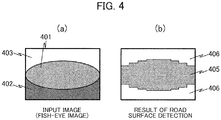
- Figs. 4 are views which show examples of road surface detection by the road surface detecting section 102.
- Fig. 4(a) shows an example of a fish-eye image obtained by shooting with the camera 20.
- a road surface 401 shows up in the center of the image
- a background 403, such as the sky shows up in the upper portion of the image
- a body 402 of the own vehicle shows up in the lower portion of the image.
- Fig. 4(b) shows an example of the result of road surface detection obtained for the image in Fig. 4(a).
- Fig. 4(b) indicates that the image in Fig.
- the observation block corresponding to the road surface 401 in Fig. 4(a) is recognized as a road surface block 405 and on the other hand the observation blocks corresponding to the body 402 and background 403 in Fig. 4(a) are recognized as non-road surface blocks 406.
- the result of road surface detection by the road surface detecting section 102 has been explained using a shot image before the distortion correction process. Actually, however, road surface detection by the road surface detecting section 102 is performed on an input image subjected to the distortion correction process by the image correcting section 101.
- the time-series verifying section 105 performs time-series verification to verify the result of detection of a road surface region by the road surface detecting section 102 according to time-series change in the arrangement of the above road surface blocks and non-road surface blocks in the input image.
- time-series verification whether part of the road surface region is hidden by another vehicle as the object of detection or whether the road shape corresponding to the road surface region has changed is verified using a plurality of temporally continuous input images generated from a plurality of shot images taken by the camera 20 at every given time interval.
- the road surface region interpolating section 106 interpolates the road surface region detected from the input image by the road surface detecting section 102 as necessary according to the result of time-series verification by the time-series verifying section 105. For example, if the time-series verifying section 105 decides that part of the road surface region is hidden by another vehicle as the object of detection, the road surface region interpolating section 106 interpolates that part into the road surface region by changing that part from the non-road surface region to the road surface region. Consequently, if the part which actually belongs to the road surface region is mistakenly decided as a non-road surface region because it is hidden by another vehicle, the part can be treated as belonging to the road surface region which it actually belongs to.
- the preferential direction selecting section 107 sets a preferential direction as a direction in which another vehicle as the object of detection should be detected preferentially, according to the traveling condition of the own vehicle. In order to judge the traveling condition of the own vehicle, a signal indicating the travel mode of the own vehicle is sent to the preferential direction selecting section 107.
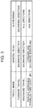
- Fig. 5 is a view which shows an example of a setting table used by the preferential direction selecting section 107 to set a preferential direction.
- the travel modes of the own vehicle include forward travel, backward travel, and parking assistance.
- the setting table in Fig. 5 shows different preferential directions for the general road and expressway.
- the preferential direction selecting section 107 sets a preferential direction suitable for the travel mode of the own vehicle and the type of road on which it travels, according to the setting table in Fig. 5 .
- the preferential direction selecting section 107 sets the backward direction of the own vehicle as the preferential direction regardless of whether it travels on a general road or expressway. Specifically, when the own vehicle is travelling forward, regardless of the type of road on which it travels, the backward direction of the own vehicle is set as the preferential direction so that another vehicle approaching from behind the own vehicle can be preferentially detected.
- the preferential direction selecting section 107 sets the backward direction of the own vehicle as the preferential direction if the road on which it travels is a general road, and sets all directions around the own vehicle as the preferential directions if the road on which it travels is an expressway.
- the backward direction of the own vehicle is set as the preferential direction so that another vehicle approaching from behind the own vehicle can be preferentially detected as in forward travel.
- the preferential direction selecting section 107 sets the forward and backward directions of the own vehicle as the preferential directions if the road on which it travels is a general road, and sets all directions around the own vehicle as the preferential directions if the road on which it travels is an expressway.
- the forward and backward directions of the own vehicle are set as the preferential directions so that another vehicle approaching from ahead of or behind the own vehicle can be preferentially detected.
- the own vehicle is not expected to park on an expressway (except in a parking area), if such a situation should happen, the degree of hazard is high enough and thus all directions around the own vehicle are set as the preferential directions so that another vehicle can be detected using the entire shot image.
- the detection region selecting section 103 sets a vehicle detection region in the input image to detect another vehicle as the object of detection according to the result of road surface region detection by the road surface detecting section 102 and the result of time-series verification by the time-series verifying section 105. At this time, if the road surface region interpolating section 106 has interpolated the road surface region according to the result of time-series verification by the time-series verifying section 105, the detection region selecting section 103 sets a vehicle detection region including the interpolated road surface region according to the result of interpolation.
- a vehicle detection region is set in consideration of the change in the road shape. Furthermore, when a direction is set as a preferential direction for the own vehicle by the preferential direction selecting section 107, a vehicle detection region is set in consideration of the preferential direction.
- the detection region selecting section 103 determines a road surface region in the input image by combining output of the road surface detecting section 102 and output of the road surface region interpolating section 106 and further sets a vehicle detection region on the determined road surface region according to output of the time-series verifying section 105 and specification by the preferential direction selecting section 107.
- Figs. 6 are views which show examples of a vehicle detection region set by the detection region selecting section 103.
- Fig. 6(a) is an example of a vehicle detection region in the case that the forward and backward directions of the own vehicle are set as the preferential directions.
- vehicle detection regions 602 and 603 set on a road surface region 601 in a fish-eye image obtained by shooting with the camera 20 correspond to the forward and backward directions of the own vehicle, respectively.
- Fig. 6(b) is an example of a vehicle detection region in the case that the backward direction of the own vehicle is set as the preferential direction.
- Fig. 6(b) is an example of a vehicle detection region in the case that the backward direction of the own vehicle is set as the preferential direction.
- a vehicle detection region 604 set on the road surface region 601 in the fish-eye image corresponds to the backward direction of the own vehicle.
- Fig. 6(c) is an example of a vehicle detection region in the case that all directions around the own vehicle are set as the preferential directions .
- a vehicle detection region 605 set on the entire road surface region 601 in the fish-eye image corresponds to all directions around the own vehicle.
- a vehicle detection region like the vehicle detection region 602 in Fig. 6(a) may be set on the road surface region in a way opposite to the example in Fig. 6(b) .
- a vehicle detection region set for each preferential direction has been explained using a shot image before the distortion correction process. Actually, however, a vehicle detection region is set on the road surface region for an input image subjected to the distortion correction process by the image correcting section 101.
- the detecting section 104 detects another vehicle present around the own vehicle from the input image according to the vehicle detection region set by the detection region selecting section 103.
- the detecting section 104 detects another vehicle showing up in the vehicle detection region by performing a given vehicle detection process on the part of the input image set as the vehicle detection region.
- the detecting section 104 can detect another vehicle by deciding whether or not a part having a feature as a vehicle is present in the vehicle detection region, for example, using a machine learning type detector similar to the one described in connection with the road surface detecting section 102. If another vehicle in the vehicle detection region is detected, the detecting section 104 sends a vehicle approach signal indicating that another vehicle is approaching. Also, for example, if an effective vehicle detection region cannot be set in the input image, like a case that the road surface detecting section 102 does not detect a road surface region, it sends a detection FAIL signal.
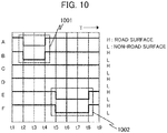
- time-series verifying section 105 Next, a concrete example of time-series verification by the time-series verifying section 105 will be described referring to Figs. 7 to 10 .
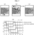
- Figs. 7 are views which explain examples of the time-series verification procedure in the case that part of the road surface region is hidden by another vehicle.
- the time-series verifying section 105 decides whether or not the road surface region is hidden by another vehicle, by time-series verification as mentioned below.
- Fig. 7(a), Fig. 7(b), and Fig. 7(c) show examples of shot images taken by the camera 20 in a time-series manner, in which the shot images are obtained in this order.
- these figures show only the right half of each shot image as a fish-eye image.
- time-series verification by the time-series verifying section 105 is performed on the result of road surface detection for an input image subjected to the distortion correction process by the image correcting section 101.
- the road surface detecting section 102 divides an input image to set a plurality of observation blocks on the input image and identifies whether each observation block is a road surface block or a non-road surface block.
- time-series verification by the time-series verifying section 105 whether or not the road surface region is hidden by another vehicle is decided according to time-series change in the arrangement of road surface blocks and non-road surface blocks in the input image. As shown in Figs.
- the road surface detecting section 102 it is desirable to identify a frequently appearing part of the road surface region in the input image, namely an area sandwiched by the borderlines between the horizon line and the body of the own vehicle, according to the known camera installation geometric information representing the installation position and installation angle of the camera 20 in the own vehicle, the angle of view of the camera 20 and the like, and provide observation blocks in the area.
- Fig. 7 (d) is a chart which shows an example of change in the result of recognition of observation blocks in the case that the input image changes as shown from Fig. 7 (a) through Fig. 7(b) to Fig. 7(c) .
- the chart shown in Fig. 7(d) indicates the results of recognition of the observation blocks A, B, C, and D in the order from top in the period from time t1 to t9, in which "H" represents a road surface block and "L" represents a non-road surface block.
- observation blocks A, B, C, and D are all set so as to correspond to the road surface part of the input image, basically they must be recognized as road surface blocks all the time. However, as shown in Fig. 7(b) , if the other vehicle 700 approaching the own vehicle shows up in the input image, part of the road surface part becomes hidden. As a consequence, as shown in Fig. 7(d) , at least one of the observation blocks A, B, C, and D, adjacent to each other, is recognized as a non-road surface block in the period from time t2 to t7 and the position of the non-road surface block shifts as time elapses. When the positions of non-road surface blocks adjacent to each other in the input image shift in a time-series manner, it may be considered that some moving body shows up in the input image and the road surface is hidden due to the moving body.
- the decision about the above moving body can be made more reliably by comparing the moving speeds S1 and S2.
- the difference between the moving speed S2 of the non-road surface blocks and the background moving speed S1 is not less than a specified value, it can be decided with certain evidence that what shows up on the road surface in the input image is a moving body and not a stationary body such as the shadow of a building.
- the background moving speed S1 can be calculated, for example, by tracking an object showing up above the horizon line in the input image through a tracking process, etc.
- the background moving speed S1 and non-road surface block moving speed S2 may be calculated not as speeds on an image but as speeds in real space.
- the time-series verifying section 105 performs time-series verification to decide whether or not part of the road surface region is hidden by another vehicle, according to the procedure explained above. Consequently, when the positions of the non-road surface blocks adjacent to each other in the input image shift in a time-series manner and the difference between the moving speed of the non-road surface blocks and the background moving speed is not less than a specified value, it can be decided that the road surface region is hidden by another vehicle as an object.
- Figs. 8 to 10 are views which explain an example of the time-series verification procedure in the case that the road shape has changed from straight to curved or a point of intersection.
- the camera 20 is a fish-eye camera and has a feature that the resolution is low in regions near the upper and lower left and right ends of a shot image. Therefore, when a curve exists on an extension of the road, its road surface shows up in a left or right end region in the shot image where the resolution is low, so an error in road surface region detection is likely to occur.
- the time-series verifying section 105 performs time-series verification as explained below to decide whether or not the road shape has changed from straight to curved or a point of intersection.
- Fig. 8(a), Fig. 8(b), and Fig. 8(c) each show an example of a shot image taken by the camera 20.
- Fig. 8(a) is an example of a shot image when the own vehicle is traveling on a straight road
- Fig. 8(b) is an example of a shot image when the own vehicle is traveling on a curved road
- Fig. 8(c) is an example of a shot image when the own vehicle is traveling at a point of intersection.
- Figs. 7(a) to 7(c) for the convenience of explanation, these figures show only the right half of each shot image as a fish-eye image.
- time-series verification by the time-series verifying section 105 is performed on the result of road surface detection for an input image subjected to the distortion correction process by the image correcting section 101.
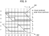
- Fig. 9 is a chart which shows an example of change in the results of recognition of observation blocks at the time when the road shape has changed from straight to curved and accordingly the shot image has changed from Fig. 8(a) to Fig. 8(b) .
- attention is paid to six observation blocks A, B, C, D, E, and F as shown in Figs. 8 (a) and 8(b) .
- the chart shown in Fig. 9 indicates the results of recognition of the observation blocks A, B, C, D, E, and F in the order from top in the period from time t1 to t9, in which "H" represents a road surface block and "L" represents a non-road surface block.
- the change in the recognition result of each observation block may be opposite to the above.
- the time-series verifying section 105 performs time-series verification to decide whether or not the road shape has changed from straight to curved, according to the procedure described above. Consequently, when in a given time period the results of road surface detection of observation blocks adjacent to each other at a first position in the input image have changed from a road surface block to a non-road surface block or from a non-road surface block to a road surface block sequentially and the results of road surface detection of observation blocks adjacent to each other at a second position under the first position have changed sequentially in a way opposite to the results of road surface detection of the observation blocks at the first position, it can be decided that the road shape has changed from straight to curved. For this reason, the road surface of a curved road which would usually tend to show up in a low-resolution part of the input image can be correctly detected as a road surface region.
- Fig. 10 is a chart which shows an example of change in the results of recognition of observation blocks at the time when the road shape has changed from straight to a point of intersection and accordingly the shot image has changed from Fig. 8(a) to Fig. 8(c) .
- the chart shown in Fig. 10 indicates the results of recognition of the observation blocks A, B, C, D, E, and F in the order from top in the period from time t1 to t9, in which "H" represents a road surface block and "L" represents a non-road surface block.
- the results of recognition of the observation blocks E and F adjacent to each other at a position under the observation blocks A and B in the input image change from a road surface block to a non-road surface block at the same time in the period from time t5 to t8 and then return to a road surface block again, like the observation blocks A and B.
- the observation blocks A and B located at the upper portion in the input image correspond to the road portion extending in the farther side direction of the point of intersection and the observation blocks E and F located at the lower portion in the input image correspond to the road portion extending in the nearer side direction of the point of intersection.
- the time-series verifying section 105 performs time-series verification to decide whether or not the road shape has changed from straight to a point of intersection, according to the procedure described above. Consequently, when in a given time period the results of road surface detection of observation blocks adjacent to each other at a first position in the input image and the results of road surface detection of observation blocks adjacent to each other at a second position under the first position have changed from a road surface block through a non-road surface block to a road surface block sequentially, it can be decided that the road shape has changed from straight to a point of intersection. For this reason, the road surface of a cross road which would usually tend to show up in a low-resolution part of the input image can be correctly detected as a road surface region.
- Fig. 11 is a diagram which shows an example of the outside recognition device according to the second embodiment of the present invention.
- the outside recognition device 1100 includes the image processing device 10 described in the first embodiment, a surrounding recognition section 1101, signal processing section 1102, and driver notifying section 1103.
- the outside recognition device 1100 is connected to a camera 20 mounted in the own vehicle like the image processing device 10 and also connected to a control section 1111, memory 1112, own vehicle control section 1113, LED 1114, speaker 1115, display 1116, and car navigation device 1117 which are mounted in the own vehicle.
- the image processing device 10 and other devices are connected to each other through a signal bus inside the own vehicle.
- the camera 20 acquires a shot image of the surroundings of the own vehicle and sends it to the image processing device 10 in the outside recognition device 1100.
- the memory 1112 temporarily holds the shot image acquired by the camera 20.
- the control section 1111 controls input/output of the shot image between the camera 20 and the outside recognition device 1100 and input/output of a vehicle control signal between the outside recognition device 1100 and the own vehicle control section 1113.
- the image processing device 10 detects another vehicle present around the own vehicle as described in the first embodiment and sends a vehicle approach signal based on the detection result to the surrounding recognition section 1101. Also, when it is difficult to detect another vehicle, a detection FAIL signal is sent to the surrounding recognition section 1101.
- the surrounding recognition section 1101 When a vehicle approach signal is sent from the image processing device 10, the surrounding recognition section 1101 performs a surrounding recognition process to recognize the surrounding environment around the own vehicle according to the signal. For example, using a shot image taken by the camera 20, it analyzes the surrounding space near and remote from the own vehicle to recognize whether or not there are other vehicles including a motorcycle and bicycle and a pedestrian and recognize whether or not there is an obstacle which hampers traveling or parking of the own vehicle. Also, when another vehicle or pedestrian is rapidly approaching the own vehicle, this is detected so that collision with the own vehicle or collision between the own vehicle and an obstacle is predicted.
- the surrounding recognition process may include a lane departure warning process to give a warning if the own vehicle departs from the lane during traveling, and a blind area warning process to give a warning when a human being or another vehicle comes in the blind area for the driver of the own vehicle.
- the surrounding recognition section 1101 sends the detection result based on the result of the surrounding recognition process and warning information to the signal processing section 1102 and also sends notification information for the driver of the own vehicle to the driver notifying section 1103 as necessary.
- the signal processing section 1102 generates a vehicle control signal to control movement of the own vehicle according to the detection result and warning information sent from the surrounding recognition section 1101 and sends it to the own vehicle control section 1113.
- the own vehicle control section 1113 controls movement of the own vehicle according to the vehicle control signal received from the signal processing section 1102 to stop the own vehicle in order to avoid collision with another vehicle or a pedestrian or change the travel direction of the own vehicle in order to avoid collision with an obstacle.
- the driver notifying section 1103 generates a warning signal to give a warning to the driver of the own vehicle according to the notification information sent from the surrounding recognition section 1101 and sends it to one of the LED 1114, speaker 1115, display 1116, and car navigation device 1117.
- each of the LED 1114, speaker 1115, display 1116, and car navigation device 1117 displays a warning or outputs a sound in a prescribed manner to warn the driver of the own vehicle of the other vehicle or pedestrian approaching the own vehicle or the existence of an obstacle.
- the surrounding recognition section 1101 can start or stop operation of the image processing device 10 by sending an ON/OFF control signal to the image processing device 10.
- the surrounding recognition section 1101 can send notification information to the driver notifying section 1103 and cause the driver notifying section 1103 to generate a warning signal according to the information and send it to one of the LED 1114, speaker 1115, display 1116, and car navigation device 1117 to notify the driver of the own vehicle that operation of the image processing device 10 has stopped.
- the outside recognition device 1100 includes the image processing device 10. Furthermore, the surrounding recognition section 1101, image processing section 1102, and driver notifying section 1103 send at least one of a warning signal to warn the driver of the own vehicle and a vehicle control signal to control movement of the own vehicle according to the result of other vehicle detection by the detecting section 104 in the image processing device 10. By doing so, the environment around the own vehicle can be recognized accurately.
- the object to be detected from a shot image is assumed to be another vehicle; however, the object is not limited thereto and instead, another type of physical body may be the object of detection.
- detection of an object using a shot image taken by the camera 20 mounted in the vehicle have been explained; however, the camera to obtain a shot image is not limited to a camera mounted in the vehicle.
- a shot image taken by any of cameras for various purposes other than an in-vehicle camera, such as a camera for street monitoring may be used to detect an object.
Landscapes
- Engineering & Computer Science (AREA)
- Physics & Mathematics (AREA)
- General Physics & Mathematics (AREA)
- Multimedia (AREA)
- Theoretical Computer Science (AREA)
- Computer Vision & Pattern Recognition (AREA)
- Signal Processing (AREA)
- Traffic Control Systems (AREA)
- Image Analysis (AREA)
- Image Processing (AREA)
- Closed-Circuit Television Systems (AREA)
Applications Claiming Priority (2)
| Application Number | Priority Date | Filing Date | Title |
|---|---|---|---|
| JP2016151351A JP6611353B2 (ja) | 2016-08-01 | 2016-08-01 | 画像処理装置、外界認識装置 |
| PCT/JP2017/027726 WO2018025811A1 (fr) | 2016-08-01 | 2017-07-31 | Dispositif de traitement d'image et dispositif de reconnaissance de l'environnement |
Publications (2)
| Publication Number | Publication Date |
|---|---|
| EP3493152A1 true EP3493152A1 (fr) | 2019-06-05 |
| EP3493152A4 EP3493152A4 (fr) | 2020-04-22 |
Family
ID=61073580
Family Applications (1)
| Application Number | Title | Priority Date | Filing Date |
|---|---|---|---|
| EP17836916.1A Withdrawn EP3493152A4 (fr) | 2016-08-01 | 2017-07-31 | Dispositif de traitement d'image et dispositif de reconnaissance de l'environnement |
Country Status (5)
| Country | Link |
|---|---|
| US (1) | US10956757B2 (fr) |
| EP (1) | EP3493152A4 (fr) |
| JP (1) | JP6611353B2 (fr) |
| CN (1) | CN109478324B (fr) |
| WO (1) | WO2018025811A1 (fr) |
Cited By (3)
| Publication number | Priority date | Publication date | Assignee | Title |
|---|---|---|---|---|
| EP3985643A4 (fr) * | 2019-06-14 | 2022-07-27 | Mazda Motor Corporation | Dispositif de reconnaissance d'environnement extérieur |
| EP3979221A4 (fr) * | 2019-06-14 | 2022-07-27 | Mazda Motor Corporation | Dispositif de reconnaissance d'environnement extérieur |
| EP3985635A4 (fr) * | 2019-06-14 | 2022-07-27 | Mazda Motor Corporation | Dispositif de reconnaissance d'environnement extérieur |
Families Citing this family (19)
| Publication number | Priority date | Publication date | Assignee | Title |
|---|---|---|---|---|
| JP6874850B2 (ja) * | 2017-10-06 | 2021-05-19 | 日本電気株式会社 | 物体検知装置、物体検知方法、及びプログラム |
| DE102018203590A1 (de) * | 2018-03-09 | 2019-09-12 | Conti Temic Microelectronic Gmbh | Surroundview-System mit angepasster Projektionsfläche |
| JP7203514B2 (ja) * | 2018-05-31 | 2023-01-13 | 株式会社デンソーテン | 走行領域判定装置、走行領域判定方法、および路面画像機械学習モデルの生成方法 |
| US11427211B2 (en) * | 2018-06-18 | 2022-08-30 | Baidu Usa Llc | Methods for handling sensor failures in autonomous driving vehicles |
| US11034357B2 (en) | 2018-09-14 | 2021-06-15 | Honda Motor Co., Ltd. | Scene classification prediction |
| US11195030B2 (en) * | 2018-09-14 | 2021-12-07 | Honda Motor Co., Ltd. | Scene classification |
| KR102581766B1 (ko) * | 2018-10-08 | 2023-09-22 | 주식회사 에이치엘클레무브 | 차량 제어 장치, 차량 제어 방법 및 차량 제어 시스템 |
| JP7103202B2 (ja) * | 2018-12-20 | 2022-07-20 | 株式会社デンソー | 画像認識装置 |
| JP7081481B2 (ja) * | 2018-12-28 | 2022-06-07 | 株式会社Jvcケンウッド | 車両用映像処理装置、車両用映像処理システム、車両用映像処理方法およびプログラム |
| JP6671603B1 (ja) * | 2019-03-01 | 2020-03-25 | KB−eye株式会社 | 管理サーバ、交通制御システム、交通制御方法および交通制御プログラム |
| JP7361482B2 (ja) * | 2019-03-27 | 2023-10-16 | 京セラ株式会社 | 画像処理装置、撮像装置、移動体及び画像処理方法 |
| JP2021128777A (ja) * | 2020-02-13 | 2021-09-02 | KB−eye株式会社 | 管理サーバ、情報処理装置、交通制御システム、交通制御方法および交通制御プログラム |
| JP7115502B2 (ja) * | 2020-03-23 | 2022-08-09 | トヨタ自動車株式会社 | 物体状態識別装置、物体状態識別方法及び物体状態識別用コンピュータプログラムならびに制御装置 |
| JP7650049B2 (ja) * | 2020-03-30 | 2025-03-24 | 株式会社ユピテル | ドライブレコーダー、プログラム、学習モデル生成方法、学習済みモデルおよびシステム等 |
| JP7359735B2 (ja) * | 2020-04-06 | 2023-10-11 | トヨタ自動車株式会社 | 物体状態識別装置、物体状態識別方法及び物体状態識別用コンピュータプログラムならびに制御装置 |
| JP7554699B2 (ja) * | 2021-03-31 | 2024-09-20 | 本田技研工業株式会社 | 画像処理装置および画像処理方法、車両用制御装置、プログラム |
| JP7802275B2 (ja) * | 2021-11-18 | 2026-01-20 | ナカシャ クリエイテブ株式会社 | 監視警告装置、監視警告方法、プログラム |
| US20240054731A1 (en) * | 2022-08-10 | 2024-02-15 | Faro Technologies, Inc. | Photogrammetry system for generating street edges in two-dimensional maps |
| US11922703B1 (en) * | 2023-04-06 | 2024-03-05 | Plusai, Inc. | Generic obstacle detection in drivable area |
Family Cites Families (20)
| Publication number | Priority date | Publication date | Assignee | Title |
|---|---|---|---|---|
| JP2570378B2 (ja) * | 1988-04-18 | 1997-01-08 | 日本電装株式会社 | 車両用標識認識装置 |
| DE69736764T2 (de) * | 1996-08-28 | 2007-01-25 | Matsushita Electric Industrial Co., Ltd., Kadoma | Lokales Positionierungsgerät und Verfahren dafür |
| JP3580475B2 (ja) * | 1998-09-14 | 2004-10-20 | 矢崎総業株式会社 | 周辺監視装置 |
| JP2003317106A (ja) * | 2002-04-26 | 2003-11-07 | Nissan Motor Co Ltd | 走行路認識装置 |
| US8503728B2 (en) * | 2007-10-30 | 2013-08-06 | Nec Corporation | Road marking image processing device, road marking image processing method, and program |
| JP2011504248A (ja) * | 2007-11-16 | 2011-02-03 | テレ アトラス ベスローテン フエンノートシャップ | 車線情報を作成する方法及び装置 |
| US8054201B2 (en) * | 2008-03-19 | 2011-11-08 | Mazda Motor Corporation | Surroundings monitoring device for vehicle |
| CN101483547B (zh) * | 2009-02-12 | 2011-05-11 | 中国人民解放军信息工程大学 | 一种网络突发事件度量评估方法及系统 |
| CN102044151B (zh) * | 2010-10-14 | 2012-10-17 | 吉林大学 | 基于光照可见度辨识的夜间车辆视频检测方法 |
| JP2013097675A (ja) * | 2011-11-02 | 2013-05-20 | Honda Elesys Co Ltd | 勾配推定装置、勾配推定方法、及び勾配推定プログラム |
| US9542605B2 (en) * | 2012-07-03 | 2017-01-10 | Clarion Co., Ltd. | State recognition system and state recognition method |
| CN103679127B (zh) | 2012-09-24 | 2017-08-04 | 株式会社理光 | 检测道路路面的可行驶区域的方法和装置 |
| WO2014054289A1 (fr) * | 2012-10-03 | 2014-04-10 | 株式会社デンソー | Système de navigation de véhicule, et dispositif de capture d'images destiné à un véhicule |
| JP5979023B2 (ja) * | 2013-01-28 | 2016-08-24 | マツダ株式会社 | 車両用撮像装置 |
| JP5874756B2 (ja) * | 2014-02-07 | 2016-03-02 | トヨタ自動車株式会社 | 区画線検出システム及び区画線検出方法 |
| EP3107069A4 (fr) * | 2014-03-24 | 2017-10-04 | Hitachi, Ltd. | Appareil de détection d'objet, procédé de détection d'objet et robot mobile |
| JP6380002B2 (ja) * | 2014-10-28 | 2018-08-29 | アイシン精機株式会社 | 周辺監視装置 |
| JP6156400B2 (ja) * | 2015-02-09 | 2017-07-05 | トヨタ自動車株式会社 | 走行路面検出装置及び走行路面検出方法 |
| JP6838340B2 (ja) * | 2016-09-30 | 2021-03-03 | アイシン精機株式会社 | 周辺監視装置 |
| WO2018111297A1 (fr) * | 2016-12-16 | 2018-06-21 | Hitachi Automotive Systems, Ltd. | Détection de route à l'aide d'informations de panneau de signalisation |
-
2016
- 2016-08-01 JP JP2016151351A patent/JP6611353B2/ja active Active
-
2017
- 2017-07-31 CN CN201780044270.4A patent/CN109478324B/zh active Active
- 2017-07-31 US US16/322,149 patent/US10956757B2/en active Active
- 2017-07-31 WO PCT/JP2017/027726 patent/WO2018025811A1/fr not_active Ceased
- 2017-07-31 EP EP17836916.1A patent/EP3493152A4/fr not_active Withdrawn
Cited By (4)
| Publication number | Priority date | Publication date | Assignee | Title |
|---|---|---|---|---|
| EP3985643A4 (fr) * | 2019-06-14 | 2022-07-27 | Mazda Motor Corporation | Dispositif de reconnaissance d'environnement extérieur |
| EP3979221A4 (fr) * | 2019-06-14 | 2022-07-27 | Mazda Motor Corporation | Dispositif de reconnaissance d'environnement extérieur |
| EP3985635A4 (fr) * | 2019-06-14 | 2022-07-27 | Mazda Motor Corporation | Dispositif de reconnaissance d'environnement extérieur |
| US11830254B2 (en) | 2019-06-14 | 2023-11-28 | Mazda Motor Corporation | Outside environment recognition device |
Also Published As
| Publication number | Publication date |
|---|---|
| JP6611353B2 (ja) | 2019-11-27 |
| WO2018025811A1 (fr) | 2018-02-08 |
| EP3493152A4 (fr) | 2020-04-22 |
| US20190156131A1 (en) | 2019-05-23 |
| US10956757B2 (en) | 2021-03-23 |
| CN109478324B (zh) | 2021-10-08 |
| CN109478324A (zh) | 2019-03-15 |
| JP2018022234A (ja) | 2018-02-08 |
Similar Documents
| Publication | Publication Date | Title |
|---|---|---|
| US10956757B2 (en) | Image processing device, outside recognition device | |
| US11461595B2 (en) | Image processing apparatus and external environment recognition apparatus | |
| JP5172314B2 (ja) | ステレオカメラ装置 | |
| US10246030B2 (en) | Object detection apparatus and driving assistance apparatus | |
| CN102649408B (zh) | 车道偏离警报装置以及车道偏离警报系统 | |
| JP6787157B2 (ja) | 車両制御装置 | |
| CN105522998B (zh) | 物体识别装置 | |
| JP6416293B2 (ja) | 自動車に接近する対象車両を自動車のカメラシステムにより追跡する方法、カメラシステムおよび自動車 | |
| CN107767697A (zh) | 用于处理交通声音数据以提供驾驶员辅助的系统和方法 | |
| JP2011118482A (ja) | 車載装置および認知支援システム | |
| JP2006331219A (ja) | 車両逸脱判定装置 | |
| JP2008186170A (ja) | 運転支援装置および運転支援方法 | |
| US9137499B2 (en) | Apparatus for detecting object approaching vehicle | |
| JP2005309797A (ja) | 歩行者警報装置 | |
| US12333826B2 (en) | Method for detecting obstacles around vehicle, electronic device and storage medium | |
| JP4968369B2 (ja) | 車載装置及び車両認識方法 | |
| JP2018163530A (ja) | 対象物検知装置、対象物検知方法、及び対象物検知プログラム | |
| JP2005309660A (ja) | 車両用右左折支援装置 | |
| JP4269862B2 (ja) | 車載用移動体検出装置 | |
| JP4848644B2 (ja) | 障害物認識システム | |
| JP6683245B2 (ja) | 画像処理装置、画像処理方法、画像処理プログラム、物体認識装置及び機器制御システム | |
| JP6253175B2 (ja) | 車両の外部環境認識装置 | |
| JP2011090490A (ja) | 障害物認識装置 | |
| JP7145227B2 (ja) | 標識認識装置 | |
| JP7193942B2 (ja) | 車両検知装置 |
Legal Events
| Date | Code | Title | Description |
|---|---|---|---|
| STAA | Information on the status of an ep patent application or granted ep patent |
Free format text: STATUS: THE INTERNATIONAL PUBLICATION HAS BEEN MADE |
|
| PUAI | Public reference made under article 153(3) epc to a published international application that has entered the european phase |
Free format text: ORIGINAL CODE: 0009012 |
|
| STAA | Information on the status of an ep patent application or granted ep patent |
Free format text: STATUS: REQUEST FOR EXAMINATION WAS MADE |
|
| 17P | Request for examination filed |
Effective date: 20190301 |
|
| AK | Designated contracting states |
Kind code of ref document: A1 Designated state(s): AL AT BE BG CH CY CZ DE DK EE ES FI FR GB GR HR HU IE IS IT LI LT LU LV MC MK MT NL NO PL PT RO RS SE SI SK SM TR |
|
| AX | Request for extension of the european patent |
Extension state: BA ME |
|
| DAV | Request for validation of the european patent (deleted) | ||
| DAX | Request for extension of the european patent (deleted) | ||
| A4 | Supplementary search report drawn up and despatched |
Effective date: 20200325 |
|
| RIC1 | Information provided on ipc code assigned before grant |
Ipc: G08G 1/16 20060101ALI20200319BHEP Ipc: G06K 9/32 20060101ALI20200319BHEP Ipc: H04N 7/18 20060101ALI20200319BHEP Ipc: G06T 7/00 20170101AFI20200319BHEP Ipc: G06K 9/00 20060101ALI20200319BHEP |
|
| STAA | Information on the status of an ep patent application or granted ep patent |
Free format text: STATUS: EXAMINATION IS IN PROGRESS |
|
| 17Q | First examination report despatched |
Effective date: 20211013 |
|
| REG | Reference to a national code |
Ref country code: DE Ref legal event code: R079 Free format text: PREVIOUS MAIN CLASS: G06T0007000000 Ipc: G06V0010250000 |
|
| GRAP | Despatch of communication of intention to grant a patent |
Free format text: ORIGINAL CODE: EPIDOSNIGR1 |
|
| STAA | Information on the status of an ep patent application or granted ep patent |
Free format text: STATUS: GRANT OF PATENT IS INTENDED |
|
| RIC1 | Information provided on ipc code assigned before grant |
Ipc: H04N 7/18 20060101ALI20230606BHEP Ipc: G08G 1/16 20060101ALI20230606BHEP Ipc: G06T 7/00 20170101ALI20230606BHEP Ipc: G06V 20/58 20220101ALI20230606BHEP Ipc: G06V 20/56 20220101ALI20230606BHEP Ipc: G06V 10/25 20220101AFI20230606BHEP |
|
| INTG | Intention to grant announced |
Effective date: 20230621 |
|
| STAA | Information on the status of an ep patent application or granted ep patent |
Free format text: STATUS: THE APPLICATION IS DEEMED TO BE WITHDRAWN |
|
| 18D | Application deemed to be withdrawn |
Effective date: 20231103 |